EP3366514B1 - Adjustable footrest for a vehicle - Google Patents
Adjustable footrest for a vehicle Download PDFInfo
- Publication number
- EP3366514B1 EP3366514B1 EP18157003.7A EP18157003A EP3366514B1 EP 3366514 B1 EP3366514 B1 EP 3366514B1 EP 18157003 A EP18157003 A EP 18157003A EP 3366514 B1 EP3366514 B1 EP 3366514B1
- Authority
- EP
- European Patent Office
- Prior art keywords
- support member
- footrest
- foot member
- foot
- storage compartment
- Prior art date
- Legal status (The legal status is an assumption and is not a legal conclusion. Google has not performed a legal analysis and makes no representation as to the accuracy of the status listed.)
- Active
Links
Images




Classifications
-
- B—PERFORMING OPERATIONS; TRANSPORTING
- B60—VEHICLES IN GENERAL
- B60N—SEATS SPECIALLY ADAPTED FOR VEHICLES; VEHICLE PASSENGER ACCOMMODATION NOT OTHERWISE PROVIDED FOR
- B60N3/00—Arrangements or adaptations of other passenger fittings, not otherwise provided for
- B60N3/06—Arrangements or adaptations of other passenger fittings, not otherwise provided for of footrests
- B60N3/063—Arrangements or adaptations of other passenger fittings, not otherwise provided for of footrests with adjustment systems
-
- B—PERFORMING OPERATIONS; TRANSPORTING
- B60—VEHICLES IN GENERAL
- B60N—SEATS SPECIALLY ADAPTED FOR VEHICLES; VEHICLE PASSENGER ACCOMMODATION NOT OTHERWISE PROVIDED FOR
- B60N3/00—Arrangements or adaptations of other passenger fittings, not otherwise provided for
- B60N3/06—Arrangements or adaptations of other passenger fittings, not otherwise provided for of footrests
-
- B—PERFORMING OPERATIONS; TRANSPORTING
- B61—RAILWAYS
- B61D—BODY DETAILS OR KINDS OF RAILWAY VEHICLES
- B61D33/00—Seats
- B61D33/0007—Details; Accessories
- B61D33/005—Head, arm or footrests
-
- B—PERFORMING OPERATIONS; TRANSPORTING
- B63—SHIPS OR OTHER WATERBORNE VESSELS; RELATED EQUIPMENT
- B63B—SHIPS OR OTHER WATERBORNE VESSELS; EQUIPMENT FOR SHIPPING
- B63B29/00—Accommodation for crew or passengers not otherwise provided for
- B63B29/02—Cabins or other living spaces; Construction or arrangement thereof
- B63B29/04—Furniture peculiar to vessels
-
- B—PERFORMING OPERATIONS; TRANSPORTING
- B64—AIRCRAFT; AVIATION; COSMONAUTICS
- B64D—EQUIPMENT FOR FITTING IN OR TO AIRCRAFT; FLIGHT SUITS; PARACHUTES; ARRANGEMENT OR MOUNTING OF POWER PLANTS OR PROPULSION TRANSMISSIONS IN AIRCRAFT
- B64D11/00—Passenger or crew accommodation; Flight-deck installations not otherwise provided for
- B64D11/06—Arrangements of seats, or adaptations or details specially adapted for aircraft seats
- B64D11/0627—Seats combined with storage means
- B64D11/0636—Personal storage means or waste disposal bags
-
- B—PERFORMING OPERATIONS; TRANSPORTING
- B64—AIRCRAFT; AVIATION; COSMONAUTICS
- B64D—EQUIPMENT FOR FITTING IN OR TO AIRCRAFT; FLIGHT SUITS; PARACHUTES; ARRANGEMENT OR MOUNTING OF POWER PLANTS OR PROPULSION TRANSMISSIONS IN AIRCRAFT
- B64D11/00—Passenger or crew accommodation; Flight-deck installations not otherwise provided for
- B64D11/06—Arrangements of seats, or adaptations or details specially adapted for aircraft seats
- B64D11/0639—Arrangements of seats, or adaptations or details specially adapted for aircraft seats with features for adjustment or converting of seats
- B64D11/0643—Adjustable foot or leg rests
-
- B—PERFORMING OPERATIONS; TRANSPORTING
- B64—AIRCRAFT; AVIATION; COSMONAUTICS
- B64D—EQUIPMENT FOR FITTING IN OR TO AIRCRAFT; FLIGHT SUITS; PARACHUTES; ARRANGEMENT OR MOUNTING OF POWER PLANTS OR PROPULSION TRANSMISSIONS IN AIRCRAFT
- B64D11/00—Passenger or crew accommodation; Flight-deck installations not otherwise provided for
- B64D11/06—Arrangements of seats, or adaptations or details specially adapted for aircraft seats
- B64D11/0646—Seats characterised by special features of stationary arms, foot or head rests
Definitions
- the present invention relates to an adjustable footrest, in particular to an adjustable footrest including a storage compartment which is suitable for use in aircraft.
- These seating arrangements provide a seat to the occupant of that particular seating arrangement however they also provide a number of beneficial features to the occupant of the seating arrangement located there behind.
- it is a common feature of such seating arrangements to incorporate a deployable tray table located upon their rear side which the occupant of the seating arrangement behind may use to support beverages and snacks.
- a further feature of such seating arrangements is the provision of a footrest which is typically located towards the lower rear portion of the seating arrangement, this allows the occupant of the seat located behind to rest their feet in a comfortable location.
- the rear portions of such seating arrangements typically incorporate some form of storage compartment in the form of a holder or netting such that the documents or electronic devices may be held therein for ease of access during transit.
- EP1116654 discloses a sleeper seating unit for an aircraft.
- DE202013009983 describes an inclinable footrest for vehicle seats, in particular for rail vehicles.
- US2013/145972 discloses a variable height support with a platform and a base supporting the platform and reconfigurable to selectively change a height of a support surface on the platform relative to a subjacent surface.
- US2012/139322 describes a footrest that includes a footplate element, an upper swing arm, and a lower swing arm, which footrest can be arranged on a wall that faces a seat, and allows several seating positions.
- the present invention provides a footrest according to claim 1. Further optional features according to the invention are described in the dependent claims 2-14.
- the front wall comprises side edges and a bottom edge, the side edges having respective upper and lower portions, with each of the respective upper portions protruding further rearward than the lower portions such as to define respective protrusions upon the side edges which extend rearward from the body of the front wall.
- pivotable coupling parts are disposed upon the protrusions.
- said support member incorporates one or more additional apertures for providing further means of entry to the storage compartment.
- said footrest comprises securing means which is configured to releasably secure the foot member to the support member in the stowed state.
- a footrest 1 generally indicated by the reference numeral 1.
- the footrest 1 is suitable for being supported on a wall such as a bulkhead or partition wall of a vehicle such as a plane, train, boat or any other suitable vehicle.
- the footrest 1 is typically supported upon a wall which is located directly in front of a passenger seating arrangement as shown in Figure 13 , with the seating arrangement being arranged such that the seat occupant faces towards the wall in-use.
- vertical axis is intended to mean the axis which extends perpendicular to the vehicle floor within which the footrest 1 is disposed in-use.
- forward is intended to mean the direction in which the occupant of the seating arrangement would face in-use, whilst the term “rearward” is intended to mean the opposing direction.
- the footrest 1 comprises a support member 3 which is shaped and dimensioned, or otherwise configured, to define a storage compartment 5.
- the storage compartment is of a type commonly referred to as a literature pocket, although it may be used to store a variety of items such as newspapers, magazines, portable electronic devices etc.
- the footrest 1 further comprises a foot member 7 for supporting one or more feet; in particular those of the occupant of the seating arrangement located rearward the wall as shown in figure 13 .
- the foot member 7 is pivotably coupled to the support member 3 such that the foot member 7 is movable between stowed and deployed states as shown in figures 4 and 8 respectively.
- the footrest 1 further comprises means for releasably retaining the foot member in the deployed state relative to the support member 9.
- the support member 3 and foot member 7 are arranged such as to provide access to the storage compartment 5 when the foot member 7 adopts either stowed or deployed states.
- the support member comprises an aperture 10, serving as an access opening for the compartment 5.
- the foot member 7 comprises a cut-out, or recessed, portion 22, wherein the aperture 10 and recess 22 coincide to define a channel into the storage compartment 5 when the foot member 7 adopts either stowed or deployed states.
- the arrangement is such that the foot member 7 does not prevent access to the contents of the compartment, e.g. by fully or partly blocking the aperture 10, irrespective of whether it is in the stowed state or deployed state.
- the foot member 7 is pivotably coupled to the support member 3 adjacent the aperture 10, the recess 22 being located adjacent the coupling location, overlapping and in register with the aperture 10 thereby exposing the mouth of the storage compartment 5.
- the recess 22 remains aligned with the aperture 10 through the entire travel of the foot member 7.
- the aperture 10 is located at the in-use top of the support member 3.
- the support member 3 comprises a body that provides the compartment 5.
- the body may be a hollow solid body or may comprise a pouch, e.g. formed one or more flexible walls of, for example, netting, leather or fabric.
- the aperture 10 is typically permanently open. In embodiments where the body is flexible, the aperture may be openable/closable by the user.
- the support member 3 comprises front and rear walls 12, 13 and opposing side walls 14, 15 and a bottom wall 16 with the storage compartment 5 being defined therebetween.
- the support member 3 is typically substantially cuboidal in shape.
- the support member 3 includes the aperture 10 which is arranged upon the support member 3 such as to provide access to the storage compartment 5 as shown in figure 8 . To this end the aperture 10 defines an open top of the support member 3 for receiving the paraphernalia into the storage compartment 5.
- the side and bottom walls 14, 15, 16 extend from the confines of body of the front wall 12, typically offset from the outward edges of the front wall 12, with the rear wall 13 extending therebetween such that the rear, side and bottom walls 13, 14, 15, 16 are narrower in width than the front wall 12.
- the front wall 12 comprises respective side edges 40, 41 and a bottom edge 42, the side edges 40, 41 having respective upper and lower portions, with each of the respective upper portions protruding further rearward than the lower portions such as to define respective protrusions 17 upon the side edges 40, 41 which extend rearward from the body of the front wall 12.
- the rear wall 13 may extend between the side walls 14, 15 typically up to the protrusions 17 or it may extend only partially between the side walls 14, 15 such that the rear wall 13 extends to a lower height than the protrusions 17.
- the side edges 140, 141 may define the side walls 114, 115 of the support member 3.
- the side walls 14, 15 may be shaped such as to comprise respective upper and lower portions, with the upper portion protruding further rearward than the lower portion such as to define respective protrusions 17 upon side walls 14, 15.
- the support member 3 may additionally incorporate one or more additional apertures 11 which are arranged such as to provide further means of entry to the storage compartment 5 and/or to provide means by which the user may view what is currently carried in the storage compartment 5.
- the one or more additional apertures 11 are typically provided upon the rear wall 13 of the support member 3. It should be understood that in-use the front wall 12 will be supported upon the wall of the vehicle, whilst the rear wall 13 faces towards the occupant of the seating arrangement.
- the bottom wall 16 should be understood as comprising the wall which extends parallel to, nearest to, the floor of the vehicle in which the footrest 1 is disposed in-use.
- the foot member 7 is shaped and dimensioned to define the recess 22 which in combination with the aperture 10 is arranged to define the channel into the storage compartment 5 in both stowed and deployed states.
- the foot member 7 may comprise a single portion however preferably it comprises a central portion 21 and an edge portion 23 which extends around at least part of the periphery of the central portion 21, such as to define a substantially U-shaped edge portion 23.
- the edge portion 23 is preferably disposed at a greater height relative to the central portion 21.
- the central portion 21 may be substantially planar and may be made of metal or plastic or a composite material or a combination thereof.
- the central portion 21 may comprise a flexible material such as a mesh or fabric or any suitable flexible material, which is coupled to the edge portion 23, typically to the inner periphery of the edge portion 23.
- the exterior edges of both the support member 3 and foot member 7 are typically chamfered or rounded to remove the presence of sharp edges which the user might contact when positioning their feet upon the footrest 1 in-use.
- the edge portion 23 may be made of plastic or rubber or metal or any other suitable material.
- the foot member 7 is pivotably coupled to the support member 3 typically by a hinge or other suitable pivotable coupling part 20.
- the foot member 7 is pivotably coupled to the support member 3, such that the foot member 7 is configured to rotate about a pivot axis defined by the pivotable coupling part 20.
- the pivot axis extends perpendicular to the vertical axis and parallel to the front and rear walls 12, 13.
- the foot member 7 lies substantially parallel, or coplanar, with the support member 3.
- the foot member 7 In the deployed state the foot member 7 is disposed obliquely with respect to the support member 3, at an angle greater than 0° with respect to the support member 3.
- the foot member 7 is typically configured to pivot between at least 0 and 90° relative to the support member 3, such that at the 90° angle the foot member 7 extends perpendicular to the support member 3.
- the foot member 7 as shown in figures 1 to 13 is typically pivotably coupled to the support member 3 by first and second pivotable coupling parts 20 located at either side of the support member 3, typically upon side edges 40, 41 of the front wall 12 or upon the side walls 14, 15.
- the recess 22 is defined between the coupling parts 20, typically being bounded by an end of the central portion 21.
- the foot member 7 is pivotably coupled to the support member 3 at exterior faces of the protrusions 16 such that in the deployed state the protrusions extend into the recess 22 whilst in the stowed state the rearward most edge of the foot member 7 is configured to substantially align with the rearward most edge of the support member 3 to define a substantially flush surface as shown in figures 2 and 4 .
- this arrangement provides for a compact arrangement of the footrest 1 in-use.
- the means for releasably retaining the support member relative to the foot member 9 is configured such that the foot member 7 can be retained in at least one deployed position, preferably a plurality of deployed positions, having a respective angular displacement relative to the support member 3, when in the deployed state.
- the means 9 preferably comprises a ratchet mechanism 30.
- the means 9 may comprise any other suitable releasable retaining arrangement.
- An example of the plurality of deployed positions can be seen in figure 6 .
- the means for releasably retaining the support member relative to the foot member 9 comprises the ratchet mechanism 30 which is included within the pivotable coupling part 20 in any conventional manner.
- the means for releasably retaining the foot member relative to the support member 109 comprises an alternative ratchet mechanism 150 which is configured to releasably retain the foot member 107 in the deployed state (preferably in any one of a plurality of angularly displaced deployment positions) relative to the support member 103.
- the ratchet mechanism 150 comprises at least one extendable support arm 151 which is pivotably coupled to the support member 103 at one end and the foot member 107 at the opposing end.
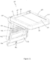
- the ratchet mechanism 150 comprises first and second support arms 150 which are disposed at either side of the support member 103, upon the side edges 140, typically towards the lower portion of the side edges 140 as shown in figures 11 and 12 .
- the support arms 150 may be coupled to the side walls 114, 115.
- the support arm(s) 151 comprise first and second elongate portions 153, 155.
- the support arms 151 may comprise an outer covering 152 for preventing the user from locating any extremities in the movable parts of the footrest 101 whilst also preventing foreign objects from entering the movable parts such as dirt, dust and debris.
- the second portion 155 shown in Figure 12 is contained within a covering 152.
- the first portion 153 is pivotably coupled to the support member 103 at one end and releasably coupled to the second portion 155 at at least one location.
- the first portion 153 is shaped and dimensioned to define a central aperture 158 with the first portion 153 further comprising a plurality of detents 157 which extend from the body of the first portion 153 into the central aperture 158, along one side of the central aperture 158, typically along one of the sides which extends parallel to the front wall 112 in the stowed state.
- the second portion 155 is coupled to the first portion 153 at one end and the foot member 103 at the opposing end, typically pivotably so.
- the first portion 153 is shaped and dimensioned to define a cavity within which the second portion 155 is disposed, at least in part, with the second portion 155 being extendable from and retractable into the cavity.
- the second portion 155 comprises a latch 159 which is disposed within the central aperture 158 of the first portion 153 and extends out of the central aperture 158.
- the latch 159 is typically provided at a lower end of the second portion 155.
- the latch 159 is configured to engage any one of the plurality of detents 157 of the first portion 153, to this end the latch 159 is configured to displace relative to the first portion 153 when the second portion 155 is extended relative to the first portion 153.
- the latch 159 Upon the extension of the second portion 155 relative to the first portion 153, the latch 159 is operable to displace along the length of the central aperture 158 such that the latch 159 may engage with the plurality of detents 157.
- the latch 159 may comprise a pin or bar or any other suitable member.
- the latch 159 is movable between an disengaging state and an engaging state as shown in figure 12A where the latch 159 is shown in the disengaging state with the arrow A indicating the direction of lateral movement of the latch 159 for assuming the engaging state.
- the latch 159 comprises resilient biasing means (not shown) such as a spring or other suitable biasing means which is configured to bias the latch 159 towards the engaging state.
- the detents 157 are configured to vary the latch 159 between the engaging and disengaging states as the second portion 155 is moved relative to the first portion 153.
- each detent 157 is ideally shaped such as to gradually narrow the width of the central aperture 158 along the length of each detent 157 such that at one point along the length of each detent 157 the width of the central aperture 158 is narrowed to the extent that that the latch 159 may displace alongside the detent 157 only in the disengaging state.
- the detents 157 typically define a sawtooth edge along the length of one side of the central aperture 158.
- the second portion 155 In the stowed state the second portion 155 is substantially retracted within the first portion 153, whilst in the deployed state the second portion 155 extends from within the first portion 153, at least in part, with the latch 159 engaging with one of the detents 157.
- the plurality of detents 157 correspond to a plurality of deployed positions with the foot member 107 being retainable at the plurality of deployed positions in the deployed state relative to the support member 103.
- the second portion 155 may be configured to receive the first portion 153 therein, at least in part.
- the support member 3, 103 and foot member 7, 107 comprise a complementary securing means 60, 160.
- the securing means 60 160 is configured to releasably secure the foot member 7, 107 to the support member 3, 103 in the stowed state.
- the securing means 60, 160 comprises a male member 61, 161 typically comprising a resilient biasing means, provided on the foot member 7,107 which is configured to engage with a female member 62, 162 provided on the support member 7, 107.
- the female member 62, 162 is disposed upon the rear wall 13, 113 or the front wall 12,112 whilst the male member 61, 161 is disposed upon the underside of the edge portion 23, typically upon lower portions thereof.
- the securing means 60, 160 may comprise cooperating magnets or a latch or any other suitable securing means.
- the foot member 7, 107 is secured in the stowed state by the securing means 60, 160 with the user being operable to access the contents of the storage compartment 5, 105 by the channel defined by the recess 22, 122 and the aperture 10, 110 in the stowed state. Displacement by the user of the foot member 7, 107 causes the foot member 7, 107 to pivot relative to the support member 103 such that the foot member 7, 107 adopts the deployed state.
- the user is operable to pivot the foot member 7, 107 about the pivot axis until they find a deployed position which they would like to retain the foot member 7, 107, wherein the means for releasably retaining the foot member relative to the support member 9, 109 is operable to retain the foot member 7, 107 in one of the deployed positions as defined by the ratchet mechanism 30, 150.
- the user may then support their feet upon the footrest 1, 101 in-use. Whilst in the deployed state the user is also operable to access the contents of the storage compartment 5, 105 by the channel defined by the recess 22, 122 and the aperture 10.
- the foot member 7, 107 can be pivoted about the pivot axis such that securing means 60, 160 secures the foot member 7, 107 relative to the support member 3, 103 with the foot member 7, 107 adopting the stowed state.
- the footrest 1, 101 may optionally include a release arrangement located upon the support member 3, 103 or foot member 7, 107 which is configured to engage the means for releasably retaining the foot member in the deployed state relative to the support member 9, 109 such that the foot member 7, 107 is movable from the deployed state to the stowed state.
- the release arrangement may comprise a lever which is coupled to the means 9, 109 by a cable arrangement.
Landscapes
- Engineering & Computer Science (AREA)
- Mechanical Engineering (AREA)
- Aviation & Aerospace Engineering (AREA)
- Transportation (AREA)
- Chemical & Material Sciences (AREA)
- Combustion & Propulsion (AREA)
- Ocean & Marine Engineering (AREA)
- Passenger Equipment (AREA)
Description
- The present invention relates to an adjustable footrest, in particular to an adjustable footrest including a storage compartment which is suitable for use in aircraft.
- It is a common feature of passenger vehicles such as planes, trains and boats for example, to have multiple rows of seating arrangements which are positioned in front of one another. These seating arrangements provide a seat to the occupant of that particular seating arrangement however they also provide a number of beneficial features to the occupant of the seating arrangement located there behind. For example it is a common feature of such seating arrangements to incorporate a deployable tray table located upon their rear side which the occupant of the seating arrangement behind may use to support beverages and snacks. A further feature of such seating arrangements is the provision of a footrest which is typically located towards the lower rear portion of the seating arrangement, this allows the occupant of the seat located behind to rest their feet in a comfortable location. Additionally the rear portions of such seating arrangements typically incorporate some form of storage compartment in the form of a holder or netting such that the documents or electronic devices may be held therein for ease of access during transit.
- The provision of the features described above is dependent on the presence of a seating arrangement being located in front of one other seating arrangement however this is not always the case, particularly in planes and trains, there are typically a number of bulkheads disposed therein. This means that the occupants of seating arrangements located behind such bulkheads do not have access to the features described above such as a footrest or storage compartment.
-
EP1116654 discloses a sleeper seating unit for an aircraft.
DE202013009983 describes an inclinable footrest for vehicle seats, in particular for rail vehicles. -
US2013/145972 discloses a variable height support with a platform and a base supporting the platform and reconfigurable to selectively change a height of a support surface on the platform relative to a subjacent surface. -
US2012/139322 describes a footrest that includes a footplate element, an upper swing arm, and a lower swing arm, which footrest can be arranged on a wall that faces a seat, and allows several seating positions. - It would be desirable to mitigate the problem outlined above.
- Accordingly the present invention provides a footrest according to
claim 1. Further optional features according to the invention are described in the dependent claims 2-14. Ideally, the front wall comprises side edges and a bottom edge, the side edges having respective upper and lower portions, with each of the respective upper portions protruding further rearward than the lower portions such as to define respective protrusions upon the side edges which extend rearward from the body of the front wall. - Preferably, wherein said pivotable coupling parts are disposed upon the protrusions.
- Optionally, said support member incorporates one or more additional apertures for providing further means of entry to the storage compartment.
- Optionally, wherein said footrest comprises securing means which is configured to releasably secure the foot member to the support member in the stowed state.
- An embodiment of the invention will now be described by way of example with reference to the accompanying drawings in which like numerals are used to denote like parts and in which:
-
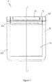
Figure 1 is a front plan view of a first embodiment of the footrest in a stowed state; -
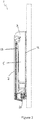
Figure 2 is a side sectional side view of the footrest in the stowed state; -
Figure 3 is a side plan view of the footrest in the stowed state; -
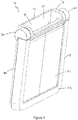
Figure 4 is a front perspective view of the footrest in the stowed state; -
Figure 5 is a side plan view of the footrest in a deployed state; -
Figure 6 is a side view of the footrest showing the footrest assuming a plurality of deployed positions; -
Figure 7 is a front plan view of the footrest in the deployed state; -
Figure 8 is a perspective view of the footrest in the deployed state; -
Figure 9 is a side plan view of a second embodiment of the footrest; -
Figure 10 is a front plan view of the second embodiment of the footrest; -
Figure 11 is a front perspective view of the second embodiment of the footrest in the deployed state; -
Figure 12 is a side sectional view of the second embodiment of the footrest in the deployed state; -
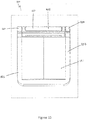
Figure 12A is a front plan view of the second portion of the support arm comprising the means for releasably retaining the foot member in the deployed state relative to the support member; -
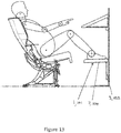
Figure 13 is a side view of the footrest showing the footrest mounted on a bulkhead with a seating arrangement and seat occupant located rearward of the footrest. - Referring to the drawings and in particular
figures 1 to 8 , there is shown a first embodiment of afootrest 1 generally indicated by thereference numeral 1. Thefootrest 1 is suitable for being supported on a wall such as a bulkhead or partition wall of a vehicle such as a plane, train, boat or any other suitable vehicle. Thefootrest 1 is typically supported upon a wall which is located directly in front of a passenger seating arrangement as shown inFigure 13 , with the seating arrangement being arranged such that the seat occupant faces towards the wall in-use. It should be understood the use of the term "vertical axis" is intended to mean the axis which extends perpendicular to the vehicle floor within which thefootrest 1 is disposed in-use. Additionally the term "forward" is intended to mean the direction in which the occupant of the seating arrangement would face in-use, whilst the term "rearward" is intended to mean the opposing direction. - The
footrest 1 comprises asupport member 3 which is shaped and dimensioned, or otherwise configured, to define astorage compartment 5. In preferred embodiments the storage compartment is of a type commonly referred to as a literature pocket, although it may be used to store a variety of items such as newspapers, magazines, portable electronic devices etc. Thefootrest 1 further comprises afoot member 7 for supporting one or more feet; in particular those of the occupant of the seating arrangement located rearward the wall as shown infigure 13 . Thefoot member 7 is pivotably coupled to thesupport member 3 such that thefoot member 7 is movable between stowed and deployed states as shown infigures 4 and8 respectively. Thefootrest 1 further comprises means for releasably retaining the foot member in the deployed state relative to thesupport member 9. Thesupport member 3 andfoot member 7 are arranged such as to provide access to thestorage compartment 5 when thefoot member 7 adopts either stowed or deployed states. Advantageously when thefootrest 1 is supported on a wall in front of a seating arrangement, the seat occupant is able to comfortably rest their feet on thefoot member 7 whilst still being able to access in the contents of thestorage compartment 5. To this end the support member comprises anaperture 10, serving as an access opening for the compartment 5.Thefoot member 7 comprises a cut-out, or recessed, portion 22, wherein theaperture 10 and recess 22 coincide to define a channel into thestorage compartment 5 when thefoot member 7 adopts either stowed or deployed states. In any event, the arrangement is such that thefoot member 7 does not prevent access to the contents of the compartment, e.g. by fully or partly blocking theaperture 10, irrespective of whether it is in the stowed state or deployed state. In preferred embodiments thefoot member 7 is pivotably coupled to thesupport member 3 adjacent theaperture 10, the recess 22 being located adjacent the coupling location, overlapping and in register with theaperture 10 thereby exposing the mouth of thestorage compartment 5. The recess 22 remains aligned with theaperture 10 through the entire travel of thefoot member 7. Typically, theaperture 10 is located at the in-use top of thesupport member 3. - The
support member 3 comprises a body that provides thecompartment 5. The body may be a hollow solid body or may comprise a pouch, e.g. formed one or more flexible walls of, for example, netting, leather or fabric. In cases where the body is solid, theaperture 10 is typically permanently open. In embodiments where the body is flexible, the aperture may be openable/closable by the user. - In the illustrated embodiment, the
support member 3 comprises front andrear walls opposing side walls bottom wall 16 with thestorage compartment 5 being defined therebetween. Thesupport member 3 is typically substantially cuboidal in shape. Thesupport member 3 includes theaperture 10 which is arranged upon thesupport member 3 such as to provide access to thestorage compartment 5 as shown infigure 8 . To this end theaperture 10 defines an open top of thesupport member 3 for receiving the paraphernalia into thestorage compartment 5. In the first embodiment the side andbottom walls front wall 12, typically offset from the outward edges of thefront wall 12, with therear wall 13 extending therebetween such that the rear, side andbottom walls front wall 12. Ideally, thefront wall 12 comprises respective side edges 40, 41 and abottom edge 42, the side edges 40, 41 having respective upper and lower portions, with each of the respective upper portions protruding further rearward than the lower portions such as to definerespective protrusions 17 upon the side edges 40, 41 which extend rearward from the body of thefront wall 12. Therear wall 13 may extend between theside walls protrusions 17 or it may extend only partially between theside walls rear wall 13 extends to a lower height than theprotrusions 17. - In the second embodiment as shown in
figures 9 to 12 the side edges 140, 141 may define theside walls 114, 115 of thesupport member 3. Theside walls respective protrusions 17 uponside walls - The
support member 3 may additionally incorporate one or moreadditional apertures 11 which are arranged such as to provide further means of entry to thestorage compartment 5 and/or to provide means by which the user may view what is currently carried in thestorage compartment 5. To this end the one or moreadditional apertures 11 are typically provided upon therear wall 13 of thesupport member 3. It should be understood that in-use thefront wall 12 will be supported upon the wall of the vehicle, whilst therear wall 13 faces towards the occupant of the seating arrangement. Furthermore thebottom wall 16 should be understood as comprising the wall which extends parallel to, nearest to, the floor of the vehicle in which thefootrest 1 is disposed in-use. - The
foot member 7 is shaped and dimensioned to define the recess 22 which in combination with theaperture 10 is arranged to define the channel into thestorage compartment 5 in both stowed and deployed states. Thefoot member 7 may comprise a single portion however preferably it comprises acentral portion 21 and anedge portion 23 which extends around at least part of the periphery of thecentral portion 21, such as to define a substantiallyU-shaped edge portion 23. Theedge portion 23 is preferably disposed at a greater height relative to thecentral portion 21. Thecentral portion 21 may be substantially planar and may be made of metal or plastic or a composite material or a combination thereof. In an alternative embodiment (not shown) thecentral portion 21 may comprise a flexible material such as a mesh or fabric or any suitable flexible material, which is coupled to theedge portion 23, typically to the inner periphery of theedge portion 23. The exterior edges of both thesupport member 3 andfoot member 7 are typically chamfered or rounded to remove the presence of sharp edges which the user might contact when positioning their feet upon thefootrest 1 in-use. Theedge portion 23 may be made of plastic or rubber or metal or any other suitable material. - The
foot member 7 is pivotably coupled to thesupport member 3 typically by a hinge or other suitablepivotable coupling part 20. Thefoot member 7 is pivotably coupled to thesupport member 3, such that thefoot member 7 is configured to rotate about a pivot axis defined by thepivotable coupling part 20. Typically, the pivot axis extends perpendicular to the vertical axis and parallel to the front andrear walls foot member 7 lies substantially parallel, or coplanar, with thesupport member 3. In the deployed state thefoot member 7 is disposed obliquely with respect to thesupport member 3, at an angle greater than 0° with respect to thesupport member 3. To this end thefoot member 7 is typically configured to pivot between at least 0 and 90° relative to thesupport member 3, such that at the 90° angle thefoot member 7 extends perpendicular to thesupport member 3. - The
foot member 7 as shown infigures 1 to 13 is typically pivotably coupled to thesupport member 3 by first and secondpivotable coupling parts 20 located at either side of thesupport member 3, typically upon side edges 40, 41 of thefront wall 12 or upon theside walls coupling parts 20, typically being bounded by an end of thecentral portion 21. Preferably, thefoot member 7 is pivotably coupled to thesupport member 3 at exterior faces of theprotrusions 16 such that in the deployed state the protrusions extend into the recess 22 whilst in the stowed state the rearward most edge of thefoot member 7 is configured to substantially align with the rearward most edge of thesupport member 3 to define a substantially flush surface as shown infigures 2 and4 . Advantageously, this arrangement provides for a compact arrangement of thefootrest 1 in-use. - The means for releasably retaining the support member relative to the
foot member 9 is configured such that thefoot member 7 can be retained in at least one deployed position, preferably a plurality of deployed positions, having a respective angular displacement relative to thesupport member 3, when in the deployed state. To this end themeans 9 preferably comprises a ratchet mechanism 30. Alternatively themeans 9 may comprise any other suitable releasable retaining arrangement. An example of the plurality of deployed positions can be seen infigure 6 . - In a first embodiment as shown in
figures 1 to 8 the means for releasably retaining the support member relative to thefoot member 9 comprises the ratchet mechanism 30 which is included within thepivotable coupling part 20 in any conventional manner. - In a second embodiment as shown in
figures 9 to 12 the means for releasably retaining the foot member relative to thesupport member 109 comprises analternative ratchet mechanism 150 which is configured to releasably retain thefoot member 107 in the deployed state (preferably in any one of a plurality of angularly displaced deployment positions) relative to thesupport member 103. Theratchet mechanism 150 comprises at least one extendable support arm 151 which is pivotably coupled to thesupport member 103 at one end and thefoot member 107 at the opposing end. Ideally, theratchet mechanism 150 comprises first andsecond support arms 150 which are disposed at either side of thesupport member 103, upon the side edges 140, typically towards the lower portion of the side edges 140 as shown infigures 11 and12 . Alternatively thesupport arms 150 may be coupled to theside walls 114, 115. The support arm(s) 151 comprise first and secondelongate portions outer covering 152 for preventing the user from locating any extremities in the movable parts of thefootrest 101 whilst also preventing foreign objects from entering the movable parts such as dirt, dust and debris. To this end, thesecond portion 155 shown inFigure 12 is contained within acovering 152. - The
first portion 153 is pivotably coupled to thesupport member 103 at one end and releasably coupled to thesecond portion 155 at at least one location. Thefirst portion 153 is shaped and dimensioned to define acentral aperture 158 with thefirst portion 153 further comprising a plurality ofdetents 157 which extend from the body of thefirst portion 153 into thecentral aperture 158, along one side of thecentral aperture 158, typically along one of the sides which extends parallel to thefront wall 112 in the stowed state. Thesecond portion 155 is coupled to thefirst portion 153 at one end and thefoot member 103 at the opposing end, typically pivotably so. Thefirst portion 153 is shaped and dimensioned to define a cavity within which thesecond portion 155 is disposed, at least in part, with thesecond portion 155 being extendable from and retractable into the cavity. Thesecond portion 155 comprises alatch 159 which is disposed within thecentral aperture 158 of thefirst portion 153 and extends out of thecentral aperture 158. Thelatch 159 is typically provided at a lower end of thesecond portion 155. Thelatch 159 is configured to engage any one of the plurality ofdetents 157 of thefirst portion 153, to this end thelatch 159 is configured to displace relative to thefirst portion 153 when thesecond portion 155 is extended relative to thefirst portion 153. Upon the extension of thesecond portion 155 relative to thefirst portion 153, thelatch 159 is operable to displace along the length of thecentral aperture 158 such that thelatch 159 may engage with the plurality ofdetents 157. Thelatch 159 may comprise a pin or bar or any other suitable member. - Preferably, the
latch 159 is movable between an disengaging state and an engaging state as shown infigure 12A where thelatch 159 is shown in the disengaging state with the arrow A indicating the direction of lateral movement of thelatch 159 for assuming the engaging state. To this end thelatch 159 comprises resilient biasing means (not shown) such as a spring or other suitable biasing means which is configured to bias thelatch 159 towards the engaging state. Advantageously, thedetents 157 are configured to vary thelatch 159 between the engaging and disengaging states as thesecond portion 155 is moved relative to thefirst portion 153. To this end eachdetent 157 is ideally shaped such as to gradually narrow the width of thecentral aperture 158 along the length of eachdetent 157 such that at one point along the length of eachdetent 157 the width of thecentral aperture 158 is narrowed to the extent that that thelatch 159 may displace alongside thedetent 157 only in the disengaging state. To this end thedetents 157 typically define a sawtooth edge along the length of one side of thecentral aperture 158. - In the stowed state the
second portion 155 is substantially retracted within thefirst portion 153, whilst in the deployed state thesecond portion 155 extends from within thefirst portion 153, at least in part, with thelatch 159 engaging with one of thedetents 157. Advantageously the plurality ofdetents 157 correspond to a plurality of deployed positions with thefoot member 107 being retainable at the plurality of deployed positions in the deployed state relative to thesupport member 103. Alternatively thesecond portion 155 may be configured to receive thefirst portion 153 therein, at least in part. - Preferably, the
support member foot member foot member support member male member female member support member female member rear wall male member edge portion 23, typically upon lower portions thereof. Alternatively the securing means 60, 160 may comprise cooperating magnets or a latch or any other suitable securing means. - In-use the
foot member storage compartment aperture foot member foot member support member 103 such that thefoot member foot member foot member support member foot member ratchet mechanism 30, 150. Advantageously the user may then support their feet upon thefootrest storage compartment aperture 10. When the user no longer wishes to rest their feet on thefootrest foot member foot member support member foot member - In an alternative embodiment (not shown) the
footrest support member foot member support member foot member means - The invention is not limited to the embodiment(s) described herein but can be amended or modified without departing from the scope of the present invention defined by the claims.
Claims (14)
- A footrest (1) for a bulkhead of a vehicle, the footrest comprising:a support member (3) comprising a storage compartment (5);a foot member (7), wherein the foot member (7) is pivotably coupled to the support member (3) such that the foot member (7) is movable between stowed and deployed states relative to the support member (3); and;means for releasably retaining the foot member in the deployed state relative to the support member (9);wherein the support member (3) and foot member (7) are arranged to provide access to the storage compartment (5) when the foot member (7) adopts either of the stowed state or the deployed state; and wherein the support member (3) comprises an aperture (10) and the foot member (7) comprises a recess (22), wherein the aperture (10) and recess (22) are arranged to define a channel into the storage compartment (5) when the foot member (7) adopts either of the stowed state or the deployed state.
- The footrest as claimed in claims 1, wherein the foot member (7) is pivotably coupled to the support member (3) by first and second pivotable coupling parts (20) located at either side of the support member (3).
- The footrest as claim in any preceding claim, wherein the means for releasably retaining the foot member in the deployed state relative to the support member (9) comprises a ratchet mechanism (30) for retaining the foot member (7) in any one of a plurality of deployed positions relative to the support member (3).
- The footrest as claimed in claim 3, wherein the ratchet mechanism (30) is incorporated within the pivotable coupling part(s) (20).
- The footrest as claimed in claim 3, wherein the ratchet mechanism (30) comprises at least one support arm (151) which is pivotably coupled to the support member (3) at one end and the foot member (7) at the opposing end; and/or wherein the support arm (151) comprises first and second elongate portions (153, 155), wherein the first portion (153) is pivotably coupled to the support member (3) at one end and releasably coupled to the second portion (155) at at least one location.
- The footrest as claimed in claim 5, wherein the first portion (153) is shaped and dimensioned to define a central aperture (158) with the first portion (153) further comprising a plurality of detents (157) which extend from the body of the first portion (153) into the central aperture, along one side of the central aperture (158); and/or wherein the detents (157) define a sawtooth edge substantially along the length of one side of the central aperture (158).
- The footrest as claimed in claims 5 or 6, wherein the second portion (155) is coupled to the first portion (153) at one end and the foot member (7) at the opposing end, wherein the first portion (153) is shaped and dimensioned to define a cavity within which the second portion (155) is disposed, at least in part, with the second portion (155) being extendable from and retractable into the cavity.
- The footrest as claimed in any of claims 5 to 7, wherein the second portion (155) comprises a latch (159) which is configured to engage the plurality of detents (157) of the first portion (153) when the second portion (155) is extended relative to the first portion (153).
- The footrest as claimed in any preceding claim, wherein the support member (3) comprises front and rear walls (12, 112, 13, 113) and opposing side walls (14, 15, 114, 115) and a bottom wall (16, 116) with the storage compartment (5, 105) being defined therebetween, such that the support member (3, 103) is substantially cuboidal in shape.
- The footrest as claimed in claims 4 and 9, wherein the side and bottom walls (14, 15, 16, 114, 115, 116) extend from the confines of body of the front wall (12, 112), offset from the edges of the front wall (12, 112) with the rear wall (13, 113) extending between the side and bottom walls (14, 15, 16, 114, 115, 116) such that the rear, side and bottom walls (13, 14, 15, 16, 113, 114, 115, 116) are narrower in width than the front wall (12, 112); and/or wherein the front wall (12, 112) comprises side edges and a bottom edge, the side edges having respective upper and lower portions, with each of the respective upper portions protruding further rearward than the lower portions such as to define respective protrusions upon the side edges which extend rearward from the body of the front wall (12, 112); and/or wherein said pivotable coupling parts (20) are disposed upon the protrusions.
- The footrest as claimed in any preceding claim, wherein said foot member (7) comprises a central portion (21) and an edge portion (23); and/or wherein said central portion (21) comprises a mesh material.
- The footrest as claimed in any preceding claim, wherein said support member (3) incorporates one or more additional apertures for providing further means of entry to the storage compartment (5) or one or more viewpoints; and/or wherein said footrest comprises securing means (60, 160) which is configured to releasably secure the foot member (7) to the support member (3) in the stowed state; and/or wherein the securing means (60, 160) comprise a male member (61, 161) provided on the foot member (7, 107) and a female member (62, 162) which is provided upon the support member (3, 103).
- The footrest as claimed in any preceding claim, wherein the mouth of the storage compartment (5) is located at the in-use top of the support member (3); and/or wherein the foot member (7) is pivotably coupled to the support member (3) at one or more side of the support member (3); and/or wherein the foot member (7) is pivotably coupled to the support member (3) adjacent the aperture, the support member (3) having a recessed portion located adjacent the coupling location to expose the mouth of the storage compartment (5).
- A seating installation comprising at least one seat facing a bulkhead, wherein a footrest (1) as claimed in any preceding claim is fixed to the bulkhead in front of said at least one seat.
Applications Claiming Priority (1)
| Application Number | Priority Date | Filing Date | Title |
|---|---|---|---|
| GB1702952.1A GB2559990B (en) | 2017-02-23 | 2017-02-23 | Adjustable footrest comprising a storage space, suitable for a bulkhead of a vehicle |
Publications (2)
| Publication Number | Publication Date |
|---|---|
| EP3366514A1 EP3366514A1 (en) | 2018-08-29 |
| EP3366514B1 true EP3366514B1 (en) | 2020-12-16 |
Family
ID=58544360
Family Applications (1)
| Application Number | Title | Priority Date | Filing Date |
|---|---|---|---|
| EP18157003.7A Active EP3366514B1 (en) | 2017-02-23 | 2018-02-15 | Adjustable footrest for a vehicle |
Country Status (3)
| Country | Link |
|---|---|
| US (1) | US10661693B2 (en) |
| EP (1) | EP3366514B1 (en) |
| GB (1) | GB2559990B (en) |
Families Citing this family (2)
| Publication number | Priority date | Publication date | Assignee | Title |
|---|---|---|---|---|
| US11202510B2 (en) | 2019-09-05 | 2021-12-21 | Reinhold Industries, Inc. | Passenger seating foot pedestal |
| US11130578B1 (en) | 2019-10-24 | 2021-09-28 | B/E Aerospace, Inc. | Adjustable ottoman |
Family Cites Families (14)
| Publication number | Priority date | Publication date | Assignee | Title |
|---|---|---|---|---|
| JPH09301014A (en) * | 1996-05-17 | 1997-11-25 | Inoac Corp | Structure of front passenger's set for automobile |
| JPH10203224A (en) * | 1997-01-21 | 1998-08-04 | Nissan Motor Co Ltd | Footrest device for vehicle occupants |
| FR2798890B1 (en) * | 1999-09-24 | 2003-05-23 | Renault | FOOTREST FOR MOTOR VEHICLE |
| US6305644B1 (en) * | 1999-11-10 | 2001-10-23 | B E Aerospace, Inc. | Aircraft cabin seat configuration with enhanced ingress/egress |
| US6352309B1 (en) * | 2000-01-13 | 2002-03-05 | Be Aerospace, Inc. | Passenger sleeper seat |
| DE10047739A1 (en) * | 2000-09-27 | 2002-04-11 | Bayerische Motoren Werke Ag | Foot rest for car seat is mounted on pivot at its base and when not in use leg support surface faces inwards and closes storage space which covers complete width and height of seat |
| US20060006704A1 (en) * | 2003-12-15 | 2006-01-12 | Be Aerospace, Inc. | Vehicle seating with storage feature |
| GB0402720D0 (en) * | 2004-02-07 | 2004-03-10 | Bentley Motors Ltd | A rest |
| NL1027526C2 (en) * | 2004-11-16 | 2006-05-17 | Conmedi | Footrest for use in vehicle in order to reduce motion sickness, includes means for altering position of foot support surface relative to seat |
| US20110241374A1 (en) * | 2008-03-31 | 2011-10-06 | Delray Graves | Vehicle floorboard storage |
| DE102010053667B4 (en) * | 2010-12-07 | 2013-03-07 | Airbus Operations Gmbh | footrest |
| US8544391B2 (en) * | 2011-12-12 | 2013-10-01 | Ancra International Llc | Variable height support |
| ITPD20120090U1 (en) * | 2012-11-19 | 2014-05-20 | Clerprem Spa | ADJUSTABLE FEET FOR INCLINATION SEATS FOR VEHICLES AND SEAT EQUIPPED WITH SUITABLE FOOTRESTS |
| EP3075603B1 (en) * | 2015-04-01 | 2018-07-11 | Volvo Car Corporation | Multi-functional catering module for arrangement in a vehicle |
-
2017
- 2017-02-23 GB GB1702952.1A patent/GB2559990B/en active Active
-
2018
- 2018-02-15 EP EP18157003.7A patent/EP3366514B1/en active Active
- 2018-02-23 US US15/903,121 patent/US10661693B2/en active Active
Non-Patent Citations (1)
| Title |
|---|
| None * |
Also Published As
| Publication number | Publication date |
|---|---|
| US10661693B2 (en) | 2020-05-26 |
| GB2559990A (en) | 2018-08-29 |
| EP3366514A1 (en) | 2018-08-29 |
| US20180236919A1 (en) | 2018-08-23 |
| GB2559990B (en) | 2019-05-22 |
| GB201702952D0 (en) | 2017-04-12 |
Similar Documents
| Publication | Publication Date | Title |
|---|---|---|
| US6347590B1 (en) | Center console stored extensible tray table | |
| US8052190B2 (en) | Multi-position cargo holder for use in vehicles | |
| US7059646B1 (en) | Cargo management system having vehicle load floor with cargo cage | |
| JP4294623B2 (en) | Vehicle storage device | |
| US7311353B1 (en) | Infant seat assembly | |
| US20120181822A1 (en) | Child Safety Seat Assembly | |
| EP1449710A2 (en) | Seat device including a stowable auxiliary seat | |
| ES2792125T3 (en) | Armrest box structure and vehicles that have the same | |
| JP5573363B2 (en) | Center console device for vehicle | |
| US20060261621A1 (en) | A modular vehicle interior component system and release latch mechanism for use with the system | |
| CN101003266A (en) | Storage structure in vehicle compartment | |
| US10661693B2 (en) | Adjustable footrest for a vehicle | |
| US11110818B2 (en) | Vehicle structure | |
| JP2011246004A (en) | Center console device for vehicle | |
| EP2311685A2 (en) | Seat device | |
| JP2003226186A5 (en) | ||
| JP4201608B2 (en) | Vehicle console device | |
| ES2300997T3 (en) | MOTOR VEHICLE UNDERSTANDING A FOLDING AND REMOVABLE REAR SEAT. | |
| EP1099595A2 (en) | Folding seat | |
| AU2006213943B2 (en) | Child seat with recess for vehicle head rest | |
| JP2003276482A (en) | Vehicular rear seat | |
| JP2010200855A (en) | Armrest | |
| JP2545993Y2 (en) | Storage bag for long objects in automobiles | |
| JPH09240357A (en) | Fixing device for bicycle on bus | |
| JP3858965B2 (en) | Jack storage structure |
Legal Events
| Date | Code | Title | Description |
|---|---|---|---|
| PUAI | Public reference made under article 153(3) epc to a published international application that has entered the european phase |
Free format text: ORIGINAL CODE: 0009012 |
|
| STAA | Information on the status of an ep patent application or granted ep patent |
Free format text: STATUS: THE APPLICATION HAS BEEN PUBLISHED |
|
| AK | Designated contracting states |
Kind code of ref document: A1 Designated state(s): AL AT BE BG CH CY CZ DE DK EE ES FI FR GB GR HR HU IE IS IT LI LT LU LV MC MK MT NL NO PL PT RO RS SE SI SK SM TR |
|
| AX | Request for extension of the european patent |
Extension state: BA ME |
|
| STAA | Information on the status of an ep patent application or granted ep patent |
Free format text: STATUS: REQUEST FOR EXAMINATION WAS MADE |
|
| 17P | Request for examination filed |
Effective date: 20190220 |
|
| RBV | Designated contracting states (corrected) |
Designated state(s): AL AT BE BG CH CY CZ DE DK EE ES FI FR GB GR HR HU IE IS IT LI LT LU LV MC MK MT NL NO PL PT RO RS SE SI SK SM TR |
|
| GRAP | Despatch of communication of intention to grant a patent |
Free format text: ORIGINAL CODE: EPIDOSNIGR1 |
|
| STAA | Information on the status of an ep patent application or granted ep patent |
Free format text: STATUS: GRANT OF PATENT IS INTENDED |
|
| INTG | Intention to grant announced |
Effective date: 20200707 |
|
| GRAS | Grant fee paid |
Free format text: ORIGINAL CODE: EPIDOSNIGR3 |
|
| GRAA | (expected) grant |
Free format text: ORIGINAL CODE: 0009210 |
|
| STAA | Information on the status of an ep patent application or granted ep patent |
Free format text: STATUS: THE PATENT HAS BEEN GRANTED |
|
| AK | Designated contracting states |
Kind code of ref document: B1 Designated state(s): AL AT BE BG CH CY CZ DE DK EE ES FI FR GB GR HR HU IE IS IT LI LT LU LV MC MK MT NL NO PL PT RO RS SE SI SK SM TR |
|
| REG | Reference to a national code |
Ref country code: GB Ref legal event code: FG4D |
|
| REG | Reference to a national code |
Ref country code: IE Ref legal event code: FG4D |
|
| REG | Reference to a national code |
Ref country code: DE Ref legal event code: R096 Ref document number: 602018010733 Country of ref document: DE |
|
| REG | Reference to a national code |
Ref country code: AT Ref legal event code: REF Ref document number: 1345299 Country of ref document: AT Kind code of ref document: T Effective date: 20210115 |
|
| PG25 | Lapsed in a contracting state [announced via postgrant information from national office to epo] |
Ref country code: FI Free format text: LAPSE BECAUSE OF FAILURE TO SUBMIT A TRANSLATION OF THE DESCRIPTION OR TO PAY THE FEE WITHIN THE PRESCRIBED TIME-LIMIT Effective date: 20201216 Ref country code: RS Free format text: LAPSE BECAUSE OF FAILURE TO SUBMIT A TRANSLATION OF THE DESCRIPTION OR TO PAY THE FEE WITHIN THE PRESCRIBED TIME-LIMIT Effective date: 20201216 Ref country code: NO Free format text: LAPSE BECAUSE OF FAILURE TO SUBMIT A TRANSLATION OF THE DESCRIPTION OR TO PAY THE FEE WITHIN THE PRESCRIBED TIME-LIMIT Effective date: 20210316 Ref country code: GR Free format text: LAPSE BECAUSE OF FAILURE TO SUBMIT A TRANSLATION OF THE DESCRIPTION OR TO PAY THE FEE WITHIN THE PRESCRIBED TIME-LIMIT Effective date: 20210317 |
|
| REG | Reference to a national code |
Ref country code: AT Ref legal event code: MK05 Ref document number: 1345299 Country of ref document: AT Kind code of ref document: T Effective date: 20201216 |
|
| REG | Reference to a national code |
Ref country code: NL Ref legal event code: MP Effective date: 20201216 |
|
| PG25 | Lapsed in a contracting state [announced via postgrant information from national office to epo] |
Ref country code: BG Free format text: LAPSE BECAUSE OF FAILURE TO SUBMIT A TRANSLATION OF THE DESCRIPTION OR TO PAY THE FEE WITHIN THE PRESCRIBED TIME-LIMIT Effective date: 20210316 Ref country code: LV Free format text: LAPSE BECAUSE OF FAILURE TO SUBMIT A TRANSLATION OF THE DESCRIPTION OR TO PAY THE FEE WITHIN THE PRESCRIBED TIME-LIMIT Effective date: 20201216 Ref country code: SE Free format text: LAPSE BECAUSE OF FAILURE TO SUBMIT A TRANSLATION OF THE DESCRIPTION OR TO PAY THE FEE WITHIN THE PRESCRIBED TIME-LIMIT Effective date: 20201216 |
|
| PG25 | Lapsed in a contracting state [announced via postgrant information from national office to epo] |
Ref country code: NL Free format text: LAPSE BECAUSE OF FAILURE TO SUBMIT A TRANSLATION OF THE DESCRIPTION OR TO PAY THE FEE WITHIN THE PRESCRIBED TIME-LIMIT Effective date: 20201216 Ref country code: HR Free format text: LAPSE BECAUSE OF FAILURE TO SUBMIT A TRANSLATION OF THE DESCRIPTION OR TO PAY THE FEE WITHIN THE PRESCRIBED TIME-LIMIT Effective date: 20201216 |
|
| REG | Reference to a national code |
Ref country code: LT Ref legal event code: MG9D |
|
| PG25 | Lapsed in a contracting state [announced via postgrant information from national office to epo] |
Ref country code: SK Free format text: LAPSE BECAUSE OF FAILURE TO SUBMIT A TRANSLATION OF THE DESCRIPTION OR TO PAY THE FEE WITHIN THE PRESCRIBED TIME-LIMIT Effective date: 20201216 Ref country code: RO Free format text: LAPSE BECAUSE OF FAILURE TO SUBMIT A TRANSLATION OF THE DESCRIPTION OR TO PAY THE FEE WITHIN THE PRESCRIBED TIME-LIMIT Effective date: 20201216 Ref country code: PT Free format text: LAPSE BECAUSE OF FAILURE TO SUBMIT A TRANSLATION OF THE DESCRIPTION OR TO PAY THE FEE WITHIN THE PRESCRIBED TIME-LIMIT Effective date: 20210416 Ref country code: LT Free format text: LAPSE BECAUSE OF FAILURE TO SUBMIT A TRANSLATION OF THE DESCRIPTION OR TO PAY THE FEE WITHIN THE PRESCRIBED TIME-LIMIT Effective date: 20201216 Ref country code: EE Free format text: LAPSE BECAUSE OF FAILURE TO SUBMIT A TRANSLATION OF THE DESCRIPTION OR TO PAY THE FEE WITHIN THE PRESCRIBED TIME-LIMIT Effective date: 20201216 Ref country code: CZ Free format text: LAPSE BECAUSE OF FAILURE TO SUBMIT A TRANSLATION OF THE DESCRIPTION OR TO PAY THE FEE WITHIN THE PRESCRIBED TIME-LIMIT Effective date: 20201216 Ref country code: SM Free format text: LAPSE BECAUSE OF FAILURE TO SUBMIT A TRANSLATION OF THE DESCRIPTION OR TO PAY THE FEE WITHIN THE PRESCRIBED TIME-LIMIT Effective date: 20201216 |
|
| PG25 | Lapsed in a contracting state [announced via postgrant information from national office to epo] |
Ref country code: PL Free format text: LAPSE BECAUSE OF FAILURE TO SUBMIT A TRANSLATION OF THE DESCRIPTION OR TO PAY THE FEE WITHIN THE PRESCRIBED TIME-LIMIT Effective date: 20201216 Ref country code: AT Free format text: LAPSE BECAUSE OF FAILURE TO SUBMIT A TRANSLATION OF THE DESCRIPTION OR TO PAY THE FEE WITHIN THE PRESCRIBED TIME-LIMIT Effective date: 20201216 |
|
| REG | Reference to a national code |
Ref country code: DE Ref legal event code: R097 Ref document number: 602018010733 Country of ref document: DE |
|
| PG25 | Lapsed in a contracting state [announced via postgrant information from national office to epo] |
Ref country code: IS Free format text: LAPSE BECAUSE OF FAILURE TO SUBMIT A TRANSLATION OF THE DESCRIPTION OR TO PAY THE FEE WITHIN THE PRESCRIBED TIME-LIMIT Effective date: 20210416 Ref country code: MC Free format text: LAPSE BECAUSE OF FAILURE TO SUBMIT A TRANSLATION OF THE DESCRIPTION OR TO PAY THE FEE WITHIN THE PRESCRIBED TIME-LIMIT Effective date: 20201216 |
|
| PLBE | No opposition filed within time limit |
Free format text: ORIGINAL CODE: 0009261 |
|
| STAA | Information on the status of an ep patent application or granted ep patent |
Free format text: STATUS: NO OPPOSITION FILED WITHIN TIME LIMIT |
|
| REG | Reference to a national code |
Ref country code: BE Ref legal event code: MM Effective date: 20210228 |
|
| PG25 | Lapsed in a contracting state [announced via postgrant information from national office to epo] |
Ref country code: LI Free format text: LAPSE BECAUSE OF NON-PAYMENT OF DUE FEES Effective date: 20210228 Ref country code: LU Free format text: LAPSE BECAUSE OF NON-PAYMENT OF DUE FEES Effective date: 20210215 Ref country code: CH Free format text: LAPSE BECAUSE OF NON-PAYMENT OF DUE FEES Effective date: 20210228 Ref country code: AL Free format text: LAPSE BECAUSE OF FAILURE TO SUBMIT A TRANSLATION OF THE DESCRIPTION OR TO PAY THE FEE WITHIN THE PRESCRIBED TIME-LIMIT Effective date: 20201216 |
|
| 26N | No opposition filed |
Effective date: 20210917 |
|
| PG25 | Lapsed in a contracting state [announced via postgrant information from national office to epo] |
Ref country code: DK Free format text: LAPSE BECAUSE OF FAILURE TO SUBMIT A TRANSLATION OF THE DESCRIPTION OR TO PAY THE FEE WITHIN THE PRESCRIBED TIME-LIMIT Effective date: 20201216 |
|
| PG25 | Lapsed in a contracting state [announced via postgrant information from national office to epo] |
Ref country code: ES Free format text: LAPSE BECAUSE OF FAILURE TO SUBMIT A TRANSLATION OF THE DESCRIPTION OR TO PAY THE FEE WITHIN THE PRESCRIBED TIME-LIMIT Effective date: 20201216 Ref country code: IE Free format text: LAPSE BECAUSE OF NON-PAYMENT OF DUE FEES Effective date: 20210215 |
|
| PG25 | Lapsed in a contracting state [announced via postgrant information from national office to epo] |
Ref country code: SI Free format text: LAPSE BECAUSE OF FAILURE TO SUBMIT A TRANSLATION OF THE DESCRIPTION OR TO PAY THE FEE WITHIN THE PRESCRIBED TIME-LIMIT Effective date: 20201216 |
|
| PG25 | Lapsed in a contracting state [announced via postgrant information from national office to epo] |
Ref country code: IS Free format text: LAPSE BECAUSE OF FAILURE TO SUBMIT A TRANSLATION OF THE DESCRIPTION OR TO PAY THE FEE WITHIN THE PRESCRIBED TIME-LIMIT Effective date: 20210416 |
|
| PG25 | Lapsed in a contracting state [announced via postgrant information from national office to epo] |
Ref country code: BE Free format text: LAPSE BECAUSE OF NON-PAYMENT OF DUE FEES Effective date: 20210228 |
|
| PG25 | Lapsed in a contracting state [announced via postgrant information from national office to epo] |
Ref country code: CY Free format text: LAPSE BECAUSE OF FAILURE TO SUBMIT A TRANSLATION OF THE DESCRIPTION OR TO PAY THE FEE WITHIN THE PRESCRIBED TIME-LIMIT Effective date: 20201216 |
|
| PG25 | Lapsed in a contracting state [announced via postgrant information from national office to epo] |
Ref country code: HU Free format text: LAPSE BECAUSE OF FAILURE TO SUBMIT A TRANSLATION OF THE DESCRIPTION OR TO PAY THE FEE WITHIN THE PRESCRIBED TIME-LIMIT; INVALID AB INITIO Effective date: 20180215 |
|
| PG25 | Lapsed in a contracting state [announced via postgrant information from national office to epo] |
Ref country code: MK Free format text: LAPSE BECAUSE OF FAILURE TO SUBMIT A TRANSLATION OF THE DESCRIPTION OR TO PAY THE FEE WITHIN THE PRESCRIBED TIME-LIMIT Effective date: 20201216 |
|
| PG25 | Lapsed in a contracting state [announced via postgrant information from national office to epo] |
Ref country code: MT Free format text: LAPSE BECAUSE OF FAILURE TO SUBMIT A TRANSLATION OF THE DESCRIPTION OR TO PAY THE FEE WITHIN THE PRESCRIBED TIME-LIMIT Effective date: 20201216 |
|
| PGFP | Annual fee paid to national office [announced via postgrant information from national office to epo] |
Ref country code: DE Payment date: 20250218 Year of fee payment: 8 |
|
| PGFP | Annual fee paid to national office [announced via postgrant information from national office to epo] |
Ref country code: FR Payment date: 20250221 Year of fee payment: 8 |
|
| PGFP | Annual fee paid to national office [announced via postgrant information from national office to epo] |
Ref country code: IT Payment date: 20250221 Year of fee payment: 8 Ref country code: GB Payment date: 20250110 Year of fee payment: 8 |
|
| PG25 | Lapsed in a contracting state [announced via postgrant information from national office to epo] |
Ref country code: TR Free format text: LAPSE BECAUSE OF FAILURE TO SUBMIT A TRANSLATION OF THE DESCRIPTION OR TO PAY THE FEE WITHIN THE PRESCRIBED TIME-LIMIT Effective date: 20201216 |