US20120139322A1 - Footrest - Google Patents
Footrest Download PDFInfo
- Publication number
- US20120139322A1 US20120139322A1 US13/313,934 US201113313934A US2012139322A1 US 20120139322 A1 US20120139322 A1 US 20120139322A1 US 201113313934 A US201113313934 A US 201113313934A US 2012139322 A1 US2012139322 A1 US 2012139322A1
- Authority
- US
- United States
- Prior art keywords
- swing arm
- surface area
- footrest
- pivot bearing
- rotary axis
- Prior art date
- Legal status (The legal status is an assumption and is not a legal conclusion. Google has not performed a legal analysis and makes no representation as to the accuracy of the status listed.)
- Granted
Links
- 230000033001 locomotion Effects 0.000 claims description 23
- 239000013598 vector Substances 0.000 description 22
- 230000007246 mechanism Effects 0.000 description 14
- 238000005192 partition Methods 0.000 description 8
- 238000009434 installation Methods 0.000 description 7
- 230000000694 effects Effects 0.000 description 4
- 238000010586 diagram Methods 0.000 description 2
- 238000000926 separation method Methods 0.000 description 2
- 238000006073 displacement reaction Methods 0.000 description 1
- 230000010006 flight Effects 0.000 description 1
- 230000010354 integration Effects 0.000 description 1
- 238000012423 maintenance Methods 0.000 description 1
- 238000000034 method Methods 0.000 description 1
- 230000008447 perception Effects 0.000 description 1
- 238000009423 ventilation Methods 0.000 description 1
- 230000000007 visual effect Effects 0.000 description 1
- 230000036642 wellbeing Effects 0.000 description 1
Images


Classifications
-
- B—PERFORMING OPERATIONS; TRANSPORTING
- B64—AIRCRAFT; AVIATION; COSMONAUTICS
- B64D—EQUIPMENT FOR FITTING IN OR TO AIRCRAFT; FLIGHT SUITS; PARACHUTES; ARRANGEMENT OR MOUNTING OF POWER PLANTS OR PROPULSION TRANSMISSIONS IN AIRCRAFT
- B64D11/00—Passenger or crew accommodation; Flight-deck installations not otherwise provided for
- B64D11/06—Arrangements of seats, or adaptations or details specially adapted for aircraft seats
- B64D11/0639—Arrangements of seats, or adaptations or details specially adapted for aircraft seats with features for adjustment or converting of seats
- B64D11/0643—Adjustable foot or leg rests
-
- B—PERFORMING OPERATIONS; TRANSPORTING
- B60—VEHICLES IN GENERAL
- B60N—SEATS SPECIALLY ADAPTED FOR VEHICLES; VEHICLE PASSENGER ACCOMMODATION NOT OTHERWISE PROVIDED FOR
- B60N2/00—Seats specially adapted for vehicles; Arrangement or mounting of seats in vehicles
- B60N2/24—Seats specially adapted for vehicles; Arrangement or mounting of seats in vehicles for particular purposes or particular vehicles
-
- B—PERFORMING OPERATIONS; TRANSPORTING
- B60—VEHICLES IN GENERAL
- B60N—SEATS SPECIALLY ADAPTED FOR VEHICLES; VEHICLE PASSENGER ACCOMMODATION NOT OTHERWISE PROVIDED FOR
- B60N3/00—Arrangements or adaptations of other passenger fittings, not otherwise provided for
- B60N3/06—Arrangements or adaptations of other passenger fittings, not otherwise provided for of footrests
- B60N3/063—Arrangements or adaptations of other passenger fittings, not otherwise provided for of footrests with adjustment systems
-
- B—PERFORMING OPERATIONS; TRANSPORTING
- B64—AIRCRAFT; AVIATION; COSMONAUTICS
- B64D—EQUIPMENT FOR FITTING IN OR TO AIRCRAFT; FLIGHT SUITS; PARACHUTES; ARRANGEMENT OR MOUNTING OF POWER PLANTS OR PROPULSION TRANSMISSIONS IN AIRCRAFT
- B64D11/00—Passenger or crew accommodation; Flight-deck installations not otherwise provided for
- B64D11/06—Arrangements of seats, or adaptations or details specially adapted for aircraft seats
- B64D11/0649—Seats characterised by special features for reducing weight
-
- Y—GENERAL TAGGING OF NEW TECHNOLOGICAL DEVELOPMENTS; GENERAL TAGGING OF CROSS-SECTIONAL TECHNOLOGIES SPANNING OVER SEVERAL SECTIONS OF THE IPC; TECHNICAL SUBJECTS COVERED BY FORMER USPC CROSS-REFERENCE ART COLLECTIONS [XRACs] AND DIGESTS
- Y02—TECHNOLOGIES OR APPLICATIONS FOR MITIGATION OR ADAPTATION AGAINST CLIMATE CHANGE
- Y02T—CLIMATE CHANGE MITIGATION TECHNOLOGIES RELATED TO TRANSPORTATION
- Y02T50/00—Aeronautics or air transport
- Y02T50/40—Weight reduction
Definitions
- the present invention relates to the technical field of seats; in particular, the present invention relates to a footrest, to an item of equipment comprising a footrest, to a seat arrangement, and to an aircraft comprising a footrest.
- An aircraft cabin often comprises a partition or separation between an economy class section and a business class section so that the interior space of an aircraft cabin is divided into several seating zones.
- the frontmost seat row of a seating zone for example the frontmost seat row in an economy class section, is designed in such a manner that passengers of the respective frontmost seat row of a cabin zone do not have the option of supporting their feet, because the passengers are, for example, seated directly behind a partition wall or behind a cabin monument.
- cabin monument refers to items of equipment in cabins, e.g. to a seat, a galley or a stowage cabinet. In the case of seats arranged in rows there is an orientation of the seats.
- the orientation of a seat is in a direction of movement or in a direction of flight.
- a backrest of the seat separates a front and a rear of the seat from each other.
- the front of a seat refers to the face of the seat on which a seat area of the seat is located. The other face is referred to as the rear of the seat.
- the orientation of the seat is selected in such a manner that the front points in the direction of flight. If at the front of the seat directly adjacent to the seat there is a partition wall or a monument, in particular if on the front there is a wall of a monument, this arrangement can be found to be annoying by a person seated on the seat.
- a footrest can be integrated in the passenger seat so as to provide enhanced comfort.
- seats may essentially be provided behind the frontmost seat rows if adequate legroom is present.
- the lack of footrests can represent a loss of comfort, even if the aircraft operator that operates an aircraft with such an aircraft cabin and a corresponding arrangement of seats without footrests has provided a generous distance between the frontmost seat rows and the monuments and/or partition walls situated in front of the aforesaid.
- a limiting seating position that does not provide an option of a foot support can in the long run be perceived as being uncomfortable by passengers, because no natural posture is supported.
- Printed publication DE 10 2007 042 489 A1 describes a vehicle seat with a legrest.
- a footrest in one embodiment, includes a footplate element, an upper swing arm, and a lower swing arm.
- the footplate element includes at least a first surface area.
- a first end of the upper swing arm in the region of an upper edge of the first surface area is rotatably arranged on the first surface area by an upper pivot joint.
- the lower swing arm in the region of a lower edge of the first surface area is rotatably arranged on the first surface area by a lower pivot joint.
- the upper edge of the first surface area is arranged so as to be essentially parallel to the lower edge of the first surface area.
- the length of the upper swing arm is shorter than the length of the lower swing arm.
- the length of the upper swing arm is shorter than the length of the first surface area.
- a second end of the upper swing arm comprises an upper pivot bearing.
- a second end of the lower swing arm comprises a lower pivot bearing.
- the upper pivot bearing and the lower pivot bearing are adapted for attaching the footrest to a wall.
- the rotary axis of the upper pivot joint, the rotary axis of the lower pivot joint, the rotary axis of the upper pivot bearing and the rotary axis of the lower pivot bearing extend so as to be essentially parallel to each other.
- an item of equipment for an aircraft in another embodiment, includes a wall, and a footrest.
- the footrest includes a footplate element, an upper swing arm, and a lower swing arm.
- the footplate element comprises at least a first surface area.
- a first end of the upper swing arm in the region of an upper edge of the first surface area is rotatably arranged on the first surface area by an upper pivot joint.
- the lower swing arm in the region of a lower edge of the first surface area is rotatably arranged on the first surface area by a lower pivot joint.
- the upper edge of the first surface area is arranged so as to be essentially parallel to the lower edge of the first surface area.
- the length of the upper swing arm is shorter than the length of the lower swing arm.
- the length of the upper swing arm is shorter than the length of the first surface area.
- a second end of the upper swing arm comprises an upper pivot bearing.
- a second end of the lower swing arm comprises a lower pivot bearing.
- the upper pivot bearing and the lower pivot bearing are adapted for attaching the footrest to a wall.
- the rotary axis of the upper pivot joint, the rotary axis of the lower pivot joint, the rotary axis of the upper pivot bearing and the rotary axis of the lower pivot bearing extend so as to be essentially parallel to each other.
- the footrest, by at least one of the pivot bearings, is attached to the wall.
- a seat arrangement in yet another embodiment, includes a wall, a seat, and a footrest.
- the footrest includes a footplate element, an upper swing arm, and a lower swing arm.
- the footplate element comprises at least a first surface area.
- a first end of the upper swing arm in the region of an upper edge of the first surface area is rotatably arranged on the first surface area by an upper pivot joint.
- the lower swing arm in the region of a lower edge of the first surface area is rotatably arranged on the first surface area by a lower pivot joint.
- the upper edge of the first surface area is arranged so as to be essentially parallel to the lower edge of the first surface area.
- the length of the upper swing arm is shorter than the length of the lower swing arm.
- the length of the upper swing arm is shorter than the length of the first surface area.
- a second end of the upper swing arm comprises an upper pivot bearing.
- a second end of the lower swing arm comprises a lower pivot bearing.
- the upper pivot bearing and the lower pivot bearing are adapted for attaching the footrest to a wall.
- the rotary axis of the upper pivot joint, the rotary axis of the lower pivot joint, the rotary axis of the upper pivot bearing and the rotary axis of the lower pivot bearing extend so as to be essentially parallel to each other.
- the wall comprises a wall surface that essentially faces the seat.
- an aircraft in yet a further embodiment, includes at least one of a footrest, an item of equipment for an aircraft, and a seat arrangement.
- the footrest includes a footplate element, an upper swing arm, and a lower swing arm.
- the footplate element comprises at least a first surface area.
- a first end of the upper swing arm in the region of an upper edge of the first surface area is rotatably arranged on the first surface area by an upper pivot joint.
- the lower swing arm in the region of a lower edge of the first surface area is rotatably arranged on the first surface area by a lower pivot joint.
- the upper edge of the first surface area is arranged so as to be essentially parallel to the lower edge of the first surface area.
- the length of the upper swing arm is shorter than the length of the lower swing arm.
- the length of the upper swing arm is shorter than the length of the first surface area.
- a second end of the upper swing arm comprises an upper pivot bearing.
- a second end of the lower swing arm comprises a lower pivot bearing.
- the upper pivot bearing and the lower pivot bearing are adapted for attaching the footrest to a wall.
- the rotary axis of the upper pivot joint, the rotary axis of the lower pivot joint, the rotary axis of the upper pivot bearing and the rotary axis of the lower pivot bearing extend so as to be essentially parallel to each other.
- the item of equipment includes a wall, and a footrest.
- the footrest includes a footplate element, an upper swing arm, and a lower swing arm.
- the footplate element comprises at least a first surface area.
- a first end of the upper swing arm in the region of an upper edge of the first surface area is rotatably arranged on the first surface area by an upper pivot joint.
- the lower swing arm in the region of a lower edge of the first surface area is rotatably arranged on the first surface area by a lower pivot joint.
- the upper edge of the first surface area is arranged so as to be essentially parallel to the lower edge of the first surface area.
- the length of the upper swing arm is shorter than the length of the lower swing arm.
- the length of the upper swing arm is shorter than the length of the first surface area.
- a second end of the upper swing arm comprises an upper pivot bearing.
- a second end of the lower swing arm comprises a lower pivot bearing.
- the upper pivot bearing and the lower pivot bearing are designed for rotatably attaching the footrest to a wall.
- the rotary axis of the upper pivot joint, the rotary axis of the lower pivot joint, the rotary axis of the upper pivot bearing and the rotary axis of the lower pivot bearing extend so as to be essentially parallel to each other.
- the footrest, by at least one of the pivot bearings is attached to the wall.
- the seat arrangement includes a wall, a seat, and a footrest.
- the footrest includes a footplate element, an upper swing arm, and a lower swing arm.
- the footplate element comprises at least a first surface area.
- a first end of the upper swing arm in the region of an upper edge of the first surface area is rotatably arranged on the first surface area by an upper pivot joint.
- the lower swing arm in the region of a lower edge of the first surface area is rotatably arranged on the first surface area by a lower pivot joint.
- the upper edge of the first surface area is arranged so as to be essentially parallel to the lower edge of the first surface area.
- the length of the upper swing arm is shorter than the length of the lower swing arm.
- the length of the upper swing arm is shorter than the length of the first surface area.
- a second end of the upper swing arm comprises an upper pivot bearing.
- a a second end of the lower swing arm comprises a lower pivot bearing.
- the upper pivot bearing and the lower pivot bearing are designed for rotatably attaching the footrest to a wall.
- the rotary axis of the upper pivot joint, the rotary axis of the lower pivot joint, the rotary axis of the upper pivot bearing and the rotary axis of the lower pivot bearing extend so as to be essentially parallel to each other.
- the wall comprises a wall surface that essentially faces the seat.
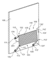
- FIG. 1 shows a footrest in a stowed-away position according to an exemplary embodiment of the present invention
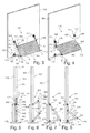
- FIG. 2 shows a footrest in an arbitrary intermediate position during the folding-out of the footrest according to an exemplary embodiment of the present invention
- FIG. 3 shows a footrest in a folded-out position for persons of small stature according to an exemplary embodiment of the present invention
- FIG. 4 shows a footrest in a folded-out position for tall persons according to an exemplary embodiment of the present invention
- FIG. 5 shows a lateral view of the position shown in FIG. 1 of the footrest according to an exemplary embodiment of the present invention
- FIG. 6 shows a lateral view of the position shown in FIG. 2 of the footrest according to an exemplary embodiment of the present invention
- FIG. 7 shows a lateral view of the position shown in FIG. 3 of the footrest according to an exemplary embodiment of the present invention
- FIG. 8 shows a lateral view of the position shown in FIG. 4 of the footrest according to an exemplary embodiment of the present invention
- FIG. 9 shows a section view of a seat arrangement of a seat with an integrated footrest to provide a better understanding of the present invention
- FIG. 10 shows a section view of a seat arrangement with a wall-mounted footrest according to an exemplary embodiment of the present invention.
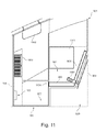
- FIG. 11 shows a section of a crew rest compartment with a seat arrangement according to an exemplary embodiment of the present invention.
- FIG. 1 shows the footrest 100 , which is arranged on the wall 108 , in a stowed-away position according to an exemplary embodiment of the present invention.
- the footrest can be a footrest for an aircraft cabin, wherein the footrest 100 is arranged on the wall 108 .
- the wall 108 is shown as a section of a wall, for example of a wall of an aircraft cabin or of a flight crew rest compartment (FCRC).
- FCRC flight crew rest compartment
- the wall 108 can also be any other section of an item of equipment, of a partition wall or of a cabin monument, for example of a seat, a galley or of a stowage cabinet.
- the footrest according to the invention can be used for any type of vehicle, although hereinafter it is essentially only described in relation to an aircraft.
- the footrest 100 comprises the footplate element 109 which in FIG. 1 is designed as a cuboid.
- a lateral surface of the footplate element 109 which lateral surface points away from the wall, comprises a footplate profile 504 , for example a ribbing or corrugation arrangement.
- the footplate element 109 comprises the upper swing arm 102 , the lower swing arm 103 , a further upper swing arm 102 ′, and a further lower swing arm 103 ′.
- the upper swing arm 102 or top swing arm 102 is rotatably attached, by means of the rotary axis 110 , to the footplate element 109 in the region of the upper edge 140 of the footplate element.
- the rotary axis 110 together with the upper swing arm 102 and the footplate element 109 forms an upper pivot joint 130 .
- the bottom swing arm 103 or lower swing arm 103 comprises the rotary axis 112 by means of which the lower swing arm 103 is rotatably attached to the footplate element 109 in the region of the lower edge 141 .
- Both the lower swing arm 103 and the upper swing arm 102 are arranged on the first surface area 101 of the footplate element, while the further lower swing arm 103 ′ and the further upper swing arm 102 ′ are arranged on the second surface area 101 ′.
- the first surface area 101 and the second surface area 101 ′ may form facing surfaces 101 , 101 ′ of the footplate element.
- the pivot joints 130 , 131 are spaced apart from each other.
- the distance between the rotary axes 110 and 112 of the pivot joints essentially corresponds to the length of the first surface area 101 and thus essentially to the length a.
- the length a In the stowed-away position the length a essentially extends along those edges of the footplate element 109 which extend so as to be essentially perpendicular to the floor 115 .
- the length a essentially extends along a normal vector or unit vector which is directed from the lower axis 112 , 112 ′ to the upper axis 110 , 110 ′ or vice versa.
- the upper edge 140 and the lower edge 141 essentially comprise the length b.
- the lower edge 141 or bottom edge 141 is distanced further away from the floor 115 than is the upper edge 140 or top edge 140 .
- the lower edge 141 is closer to the floor 115 than is the upper edge 140 .
- In the region of the upper edge 140 there is also an upper edge of the first surface area 101 .
- In the region of the lower edge 141 there is also a lower edge of the first surface area 101 .
- the upper edge of the first surface area 101 is essentially arranged at a right angle to the upper edge 140 of the footplate element 109 .
- the lower edge of the first surface area 101 is essentially arranged at a right angle to the lower edge 141 of the footplate element 109 .
- the lower edge of the first surface area and the upper edge of the first surface area are essentially arranged at a right angle to a length of the first surface area; they essentially determine the height of the footplate element and are thus referred to as height edges
- the first surface area 101 or first face area 101 is arranged so as to be essentially at a right angle or orthogonal to the wall 108 .
- the upper pivot bearing 104 On the second end of the upper swing arm 102 the upper pivot bearing 104 is arranged. On the second end of the lower swing arm 103 the lower pivot bearing 105 is formed.
- the upper pivot bearing 104 makes possible a planar movement of the upper swing arm 102 .
- the lower pivot bearing 105 makes possible a planar movement of the lower swing arm 103 .
- the upper pivot bearing 104 and the lower pivot bearing 105 are installed to the wall 108 in such a manner that the pivot bearings 104 , 105 are arranged in a line. In other words, this may mean that in a stowed-away position corresponding edges of the pivot bearings 104 , 105 are situated on a shared imaginary line or reference line, i.e. that the edges of the pivot bearings are aligned. It may thus be ensured that the swing arms essentially move in the same plane. Examples of reference lines are indicated by dashes in FIG. 3 .
- the footplate element 109 which is in the shape of a cuboid, comprises length edges of the length a, width edges of the length b, and height edges of the length c.
- the length edges extend so as to be essentially parallel to a normal vector from the lower rotary axis 112 , 112 ′ to the upper rotary axis 110 , 110 ′.
- the width edges extend so as to be essentially parallel to the rotary axes 110 , 110 ′, 112 , 112 ′.
- the height edges extend so as to be essentially perpendicular to a surface area that is defined by a normal vector through at least one of the rotary axes 110 , 110 ′, 112 , 112 ′ and by a normal vector that points from the lower rotary axis 112 , 112 ′ to the upper rotary axis 110 , 110 ′ or vice versa.
- the plane in which this surface area is situated may be designated the footplate plane.
- the first surface area 101 and the second surface area 101 ′ are defined by the length edges and the height edges.
- the width edge is longer than the length edge, and the length edge is longer than the height edge.
- the cuboid 109 comprises a symmetry plane that intersects the footplate area in the straight line 120 and that is shown in a dashed line in FIG. 1 .
- the symmetry plane extends so as to be essentially parallel to the first surface area 101 and to the second surface area 101 ′.
- the footrest in particular the cuboid, is mirror symmetrical.
- the mirror plane represents an imaginary plane that is orthogonal to the footplate area.
- the mirror plane and the footplate area essentially form a right angle.
- the footplate area, the footplate surface area or the footplate plane is defined by a length edge of the length a and a width edge of the length b, wherein the footplate area of the stowed-away position shown in FIG. 1 is that surface area of the cuboid, which surface area is furthest away from the wall 108 .
- the stowed-away position is a position in which the footplate element 109 , in particular the footplate area, is situated so as to be essentially parallel to the wall 108 .
- Corresponding objects are, for example, the upper swing arm 102 and the further upper swing arm 102 ′, the rotary axis 110 and the rotary axis 110 ′, the first surface area 101 and the second surface area 101 ′, the upper pivot bearing 104 and the further upper pivot bearing 104 ′, the rotary axis 111 and the rotary axis 111 ′, the rotary axis 112 and the rotary axis 112 ′, the lower swing arm 103 and the further lower swing arm 103 ′, the lower pivot bearing 105 and the further lower pivot bearing 105 ′, as well as the rotary axis 113 of the lower pivot bearing 105 and the rotary axis 113 ′ of the further lower pivot bearing 105 ′.
- the upper swing arm or the further upper swing arm 102 , 102 ′ comprise the length o
- the lower swing arm 103 and the further lower swing arm 103 ′ comprise the length u.
- the length o is shorter than the length u.
- the length o is, however, also shorter than the length a of the footplate element 109 .
- the length o can, however, also be longer than the length a of the footplate element 109 or it can be essentially the equal length or the same length.
- the distance of the rotary axis 110 of the upper pivot joint 130 and of the rotary axis 111 of the upper pivot bearing 104 is essentially determined by the length of the upper swing arm 102 , and is thus essentially the length o.
- the same may analogously apply to the distance of the rotary axis 110 ′ of the further upper pivot bearing 130 ′ and of the rotary axis 111 ′ of the further upper pivot bearing 104 ′.
- the distance of the rotary axis 112 of the lower pivot joint 131 from the rotary axis 113 of the lower pivot bearing 105 may essentially be determined by the length of the lower swing arm 103 and may thus be u. The same may analogously apply to the distance of the rotary axis 112 ′ of the further lower pivot joint 131 ′ and of the rotary axis 113 ′ of the further lower pivot bearing 105 ′.
- any distances that are necessary for the stable affixation of the rotary axes 110 , 110 ′, 111 , 111 ′, 112 , 112 ′, 113 , 113 ′ in the swing arms or pivot bearings are neglected, although they are also present.
- the distance between the rotary axis 110 of the upper pivot joint 130 and the rotary axis 112 of the lower pivot joint 131 may essentially be determined by the length edge of the first surface area 101 and may thus essentially be a. The same applies analogously to the distance of the rotary axes 110 ′ and 112 ′.
- the footplate element 109 projects from the wall 108 and forms a free passage area 106 , which in FIG. 1 is shown as a shaded surface area 106 .
- the passage area forms a space region 106 .
- this space region 106 can essentially without any loss of foot space open a passage between the floor 115 and the footplate element 109 , in other words underneath the footplate element in the foot space.
- the passage 109 can essentially be regarded as a space underneath the seat of a passenger in front.
- a seat may be described which on its rear pointing away from the seat area comprises the footrest 100 .
- the upper swing arm 102 ′, the footplate element 109 , the lower swing arm 103 ′, and the pivot bearings 104 ′ and 105 ′ form a four-element pivot-joint gear arrangement.
- An essentially unstable position in the stowed-away position can result in vibration of the footplate element in the folded-in state because it can move both backwards, i.e. in the direction of flight or in the direction of the wall, and forwards, i.e. in the direction of the seat.
- a direction of movement can, for example, be specified by a spring, a magnet or an eccentric bearing arrangement with the upper pivot bearings 104 , 104 ′ in that the distance between the axis of the bearing and the wall is reduced. With this eccentric arrangement a weight force in the direction of folding-out, i.e. in the direction of the seat, can be generated.
- Corresponding magnets provided on the footplate element and on the wall can also make possible stable stowing-away of the footrest.
- Folding out the footrest can take place more easily when a force in the region of the lower pivot joints 131 , 131 ′ directed away from the wall 108 is exerted than is the case, for example, if said force is applied, for example, in the region of the upper pivot joints 130 , 131 ′.
- a handle can be provided in the region of the lower pivot joints 131 , 131 ′, i.e. on a lower width edge of the footplate element 109 .
- the stowed-away position shown in FIG. 1 represents an unstable position.
- a rotary axis of the upper pivot bearings 104 , 104 ′ and at the same time of the lower pivot bearings 105 , 105 ′ can be arranged at a larger distance to the wall than the other rotary axes 110 , 110 ′, 112 , 112 ′ so that the footplate element in its stowed-away position is pushed against the wall by its own weight force. Consequently, by means of eccentric positioning of the swing arm bearings, in particular of the rotary axes of the pivot bearings 104 , 105 , 104 ′, 105 ′, a force can be generated.
- the axes of the upper pivot bearings 104 , 104 ′ can be arranged at a smaller distance than the axes of the lower pivot bearings 105 , 105 ′ in order to achieve the effect of eccentrically positioning.
- the broadside of the cuboid 109 is formed by the edges of the lengths c and b.
- the swing arms 102 , 103 , 102 ′, 103 ′ rest essentially at right angles to the surface areas formed by the broadside of the cuboid 109 against the cuboid.
- the distance of the symmetrically arranged pivot bearings 104 , 104 ′ is dimensioned such that in the stowed-away position the footplate element 109 is arranged between the upper pivot bearing 104 , the upper swing arm 102 , the further upper swing arm 102 ′, and the further upper pivot bearing 104 ′.
- the height of the pivot bearings 104 , 104 ′, 105 , 105 ′ by which height the pivot bearing projects from the wall essentially corresponds to the length c of the height edge of the cuboid 109 and thus comprises the height c.
- the width of the swing arms 102 , 102 ′, 103 , 103 ′ also essentially corresponds to the length c.
- the footplate area of the footplate element 109 is the surface area of the footrest 100 , which surface area is spaced apart furthest from the wall 108 .
- the footplate area is defined by the edges of the length a and the length b.
- FIG. 2 shows the footrest 100 in an arbitrary intermediate position during the folding-out of the footrest 100 .
- FIG. 2 shows that the footplate element 109 has been moved away from the wall 108 so that between the wall 108 and the footplate element 109 essentially a distance 201 has formed. In this process the footplate element 109 has rotated slightly.
- the rotary axes 111 , 113 , 111 ′ (not visible in FIG. 2 ), 113 ′ of the pivot bearings 104 , 105 , 104 ′ (not visible in FIG. 2 ), 105 ′ are situated on a shared plane, while the rotary axes 110 , 110 ′ (not visible in FIG.
- 112 , 112 ′ (not visible in FIG. 2 ) of the upper pivot joints 130 , 130 ′ and of the lower pivot joints 131 , 131 ′ are at a distance from the shared plane of the pivot bearings.
- a distance between a seat (not shown in FIG. 2 ) and the footplate element 109 has been reduced.
- the seat should essentially be opposite the wall 108 , and consequently in this intermediate position the footrest 100 can already be reached more easily by a person seated in the seat than is the case in the stowed-away position of FIG. 1 .
- FIG. 3 shows the footrest 100 according to an exemplary embodiment of the present invention in a folded-out position for persons of small stature or for smaller persons.
- the axis 110 of the pivot joint 130 respectively the axis 112 of the pivot joint 131 describes a circular movement on the axis 111 of the pivot bearing 104 and on the axis 113 of the pivot bearing 105 , respectively.
- the radius of the circular movement of the rotary axis of the upper pivot joint 130 essentially corresponds to the length o of the upper swing arm.
- the radius of the circular movement of the rotary axis 112 of the lower pivot joint 131 essentially corresponds to the length u of the lower swing arm.
- the folded-out position for persons of small stature corresponds to an alignment of the footplate element 109 or of the rotary axes 110 , 110 ′, 111 , 111 ′, 112 , 112 ′ so that the rotary axes 110 , 110 ′, 111 , 111 ′, 112 , 112 ′ are essentially situated on a shared plane.
- the footplate plane which is essentially defined by the length edge and width edge, may be situated in this shared plane.
- This shared plane in particular if the plane is assumed to comprise a height c rather than being considered a dimensionless ideal plane, is essentially defined by the width edge and the length edge of the cuboid 109 .
- the term “plane” can refer to a plane with dimensions in all spatial directions.
- the footplate plane is essentially formed by a normal vector along the rotary axis 112 of the lower pivot joint 131 and along a normal vector that extends from the rotary axis 112 of the lower pivot joint 131 to the rotary axis 110 of the upper pivot joint 130 .
- the footplate plane may also be formed by a normal vector through the rotary axis 110 of the upper pivot joint 130 and by a normal vector that extends from the rotary axis 110 of the upper pivot joint 130 in the direction of the rotary axis 112 of the lower pivot joint 131 .
- an edge of the upper swing arm 102 , 102 ′ represents a continuation of a length edge of the cuboid so that the rotary axis 112 of the upper pivot bearing 131 is essentially situated at a distance of o+a from the rotary axis 111 of the upper pivot bearing 104 .
- the axis 112 is essentially situated at a distance u from the axis 113 of the lower pivot bearing 105 .
- the rotary axes 112 , 112 ′ of the lower pivot joints 131 , 131 ′ and the rotary axes 113 , 113 ′ of the lower pivot bearings 105 , 105 ′ define a further plane, which intersects the footplate plane at an angle ⁇ 1 .
- the axes 112 , 112 ′ and 113 , 113 ′ are situated in such a plane.
- the rotary axes 112 and 112 ′ represent an intersecting line between the footplate plane and the plane, defined by the swing arm 103 and by the rotary axes 113 , 112 , 112 ′, 113 ′, 103 ′, of the so called lower swing arm plane.
- the angle ⁇ 1 is formed between the wall and the footplate plane.
- a plane or surface area is defined by the upper swing arm 102 , by the first surface area 101 and the lower swing arm 103 , wherein the first surface area 101 , the swing arm 102 , and the swing arm 103 are essentially situated in this plane.
- the surface area defined in this manner is arranged so as to be essentially orthogonal to the footplate plane.
- a normal vector along the axes 112 , 112 ′ of the lower pivot joints and along the length edge of the length a of the first surface area 101 i.e. a normal vector directed from the axis 112 , 112 ′ of the lower pivot joint 131 to the axis 110 , 110 ′ of the upper pivot joint 130 , may essentially define the footplate plane with a height c. This may mean that the footplate element or footboard essentially determines the footplate plane.
- the normal vector along the rotary axes 112 , 112 ′ of the lower pivot bearing 131 together with a normal vector along a longitudinal direction of the lower swing arm 103 e.g.
- a normal vector that is directed from the rotary axis 112 to the rotary axis 113 may define a further plane or plane of the lower swing arm or a lower swing arm plane, wherein these two planes intersect at an angle ⁇ 1 .
- the planes may not be assumed to be ideal planes with a dimension of 0 but instead to have a finite dimension, for example the height c.
- FIG. 4 shows the footrest in a maximum folded-out position for tall persons.
- the rotary axes 110 , 110 ′, 111 , 111 ′ and 113 , 113 ′ are situated in a shared plane that is parallel to the wall 108 .
- the footplate plane is essentially defined or spanned by a normal vector extending through the rotary axis 112 or 112 ′ and a normal vector along a longitudinal side of the first surface area 101 , wherein the normal vector points from the rotary axis 112 in the direction of the rotary axis 110 of the upper pivot joint 130 .
- the planes may be assumed to be planes with a certain dimension, for example the height c.
- the rotary axis 110 of the upper pivot joint 130 or the rotary axis 110 ′ of the upper pivot joint 130 ′ comes to rest between the upper pivot bearing 104 or 104 ′ and the lower pivot bearing 105 or 105 ′ (not shown in FIG. 4 ).
- the angle ⁇ 2 forms, wherein the angle ⁇ 2 is smaller than the angle ⁇ 1 .
- a plane defined or spanned by a normal vector along the rotary axes 110 , 110 ′ of the upper pivot joints 130 , 130 ′ and by a normal vector that is directed from the rotary axes 110 , 110 ′ of the upper pivot joints 130 , 130 ′ in the direction of the rotary axes 111 , 111 ′ of the upper pivot bearings 104 , 104 ′ may be designated a plane of the upper swing arm or as upper swing arm plane.
- An angle 2 may form essentially between the wall and the footplate plane or between the plane of the upper swing arm and the footplate plane.
- the angles 1 , 2 , 1 , 2 are essentially determined by the circumstances of the swing arm mechanism and the arrangement of the pivot bearings relative to each other.
- FIG. 5 shows a lateral view of the footrest 100 in the stowed-away position according to FIG. 1 .
- the footplate element 109 comes to rest so as to be essentially parallel to the wall 108 .
- the footplate element 109 comprises a height c, so that the footplate profile 504 affixed to the footplate area is essentially arranged at a distance c from the wall.
- the footplate area may be that surface of the footplate element 109 which is provided as a foot support.
- the wall 108 can comprise a projection 501 that comprises a height c 1 or thickness c 1 , wherein the projection 501 further comprises a recess 502 that is provided so that the footplate element 109 can be folded into the projection 501 or into the recess 502 in such a manner that the footplate area 500 including the footplate profile 504 finishes off so as to be essentially flush with the surface 503 of the projection so that the footrest 100 essentially comes to rest between the wall 108 and the surface of the projection 503 .
- the surface 503 of the wall can essentially be continued by the footplate area 500 .
- the thickness c 1 of the projection 501 essentially corresponds to the height c of the footplate element 109 .
- FIG. 5 shows that the rotary axes 113 , 112 , 111 , 110 are essentially situated in the same plane. Essentially also in the rest position according to FIG. 5 the lower swing arm 103 , the footplate element 109 and the upper swing arm 102 are situated in this plane. A good look at the footplate plane, the plane of the upper swing arm, and the plane of the lower swing arm shows that these planes are essentially situated on top of each other or that their normal vectors are situated so as to be essentially parallel to each other.
- the distance between the rotary axes 110 , 111 , 115 , 113 and the wall 108 is essentially half c/2 the height c of the footplate element 109 .
- FIG. 5 shows a shorter distance between the swing arms 102 , 103 and the wall 108 , or between the footplate element 109 and the wall 108 , which distance should, however, be ignored in the consideration of the sizes.
- FIG. 6 shows a lateral view of the footrest 100 in the intermediate position shown in FIG. 2 .
- the rotary axes 110 , 111 , 112 , 113 can comprise a click-lock mechanism.
- the diagram shows that a distance 201 has formed between the footplate element 109 or the corresponding footplate element plane and the wall 108 , wherein the footplate element 109 has been displaced in such a manner that the footplate plane and a surface area or plane formed by the wall 108 intersect.
- the wall plane is essentially formed by a normal vector through the rotary axis 111 of the upper pivot bearing 104 and a normal vector that extends from the rotary axis 111 of the upper pivot bearing 104 in the direction of the rotary axis 113 of the lower pivot bearing 105 .
- the footplate plane and the wall plane intersect in an intersection, wherein this intersection essentially comprises a shorter distance to the rotary axis 111 of the upper pivot bearing 104 than to the rotary axis 113 of the lower pivot bearing 105 .
- FIG. 7 shows a lateral view of the footrest 100 of FIG. 3 in its folded-out position for persons of small stature.
- the footplate element 109 in particular the footplate plane, intersects the wall plane essentially in the rotary axis 111 of the upper pivot bearing 104 so that as a result of the movement from the intermediate position of FIG. 6 to the position of FIG. 7 the intersection has moved so as to be closer to the rotary axis 111 of the upper pivot bearing 104 .
- the distance between the upper pivot bearing 104 and the lower pivot bearing 105 is equal to the length 1 .
- the distance between the upper pivot bearing 104 and the lower pivot bearing 105 has not changed as a result of the movement of the footplate area 109 .
- the pivot bearings 104 and 105 as well as the pivot joints 130 and 131 can comprise a click-lock mechanism that stabilizes the folded-out position for persons of small stature.
- the movement from the intermediate position of FIG. 6 to the folded-out position for persons of small stature can be supported by the gravitational force of the footplate element 109 , wherein the aforesaid can be pointed in the direction of the floor 115 .
- the angle ⁇ 1 forms, while between the plane of the upper swing arm, in particular of the footplate plane, and the wall plane the angle ⁇ 1 is formed.
- the plane of the upper swing arm and footplate plane are positioned so as to be essentially one on top of the other according to FIG. 7 , i.e. they are situated in a shared plane.
- FIG. 8 shows a lateral view of the footrest in its maximum folded-out position for tall persons as shown in FIG. 4 .
- the diagram shows that the intersection between the footplate plane and the wall plane or between the footplate plane and the plane of the upper swing arm in this position essentially extends through the rotary axis 110 of the upper pivot joint 130 , wherein the rotary axis 110 of the upper pivot joint 130 comes to rest between the rotary axis 111 of the upper pivot bearing 104 and the rotary axis 113 of the lower pivot bearing 105 .
- the footplate plane intersects the plane of the upper swing arm essentially at the angle 2 .
- the footplate plane intersects the plane of the lower swing arm essentially along the rotary axis 112 of the lower pivot bearing 131 essentially at the angle 2 .
- the lower pivot bearing 105 is arranged at a shorter distance to the floor 115 than is the upper pivot bearing 104 . Furthermore, in relation to all the positions the distance between the upper pivot joint 130 and the floor 115 is greater than the distance between the lower pivot joint 131 and the floor 115 .
- the floor 115 can be the floor or foot region of an aircraft cabin.
- FIG. 9 shows a seat 900 in a crew rest compartment 901 , wherein the crew rest compartment comprises a rear wall 902 and a front wall or partition wall 108 .
- the wall 108 is spaced apart from the rear wall 902 by the distance 903 .
- the seat 900 comprises the backrest 904 and the seat area 905 as well as the footrest 906 .
- the footrest 906 is integrated in the seat 900
- FIG. 9 shows an extended position 906 a and a stowed-away position 906 b of the integrated footrest.
- the seat 900 and the footrest 906 are situated above the floor 115 or cabin floor 115 in the foot region 907 .
- an overhang 908 above the seat installation region 909 must be provided that causes the seat 900 to have to be arranged at a large distance from the rear wall 902 , which distance corresponds at least to the overhang 908 .
- FIG. 10 shows the crew rest compartment 901 that comprises the footrest 100 according to the invention, wherein the footrest 100 is shown in a folded-out position 100 a and in a stowed-away position 100 b.
- a space region 1000 which essentially comprises the height c, is lost because the footrest 100 is stowed away.
- the distance between the backrest 904 and the rear wall 901 is shorter in FIG. 10 than is the distance between the backrest 904 and the rear wall 902 .
- the available installation space 903 in FIG. 9 is the same as that in FIG. 10 .
- FIG. 11 shows a simplified lateral view of a crew rest compartment (FCRC) or flight crew rest compartment in a long-range aircraft.
- FCRC crew rest compartment
- This section of a three-dimensional illustration shows the crew rest compartment 901 with the rear wall 902 , wherein the rear wall 902 is formed by the space 909 for a galley.
- the footrest 100 is arranged in the foot region 907 , opposite the seat 900 which comprises a backrest 904 and a seat area 905 .
- the footrest 100 is arranged at a shorter distance from the seat area 905 than it is from the backrest 904 .
- the seat 900 also shows the belt 1100 as well as a window 1101 arranged beside the seat, and a maintenance duct 1102 arranged in the sidewall, as well as the ventilation slits 1103 arranged in the sidewall.
- the floor 115 is formed by the cabin ceiling of a passenger cabin situated underneath the crew rest compartment.
- the footrest 100 is arranged on the wall 108 , wherein both the footrest 100 and the wall 108 are arranged at a distance opposite to the seat 900 .
- the distance between the wall and the seat 900 is greater than the distance between the footrest 100 and the seat or a plane that extends along a front edge 1104 of the seat area 905 .
- the foot region 907 that has been enlarged by means of the footrest 100 can ensure adequate legroom even in confined seating configurations.
- the installation space 903 predetermined by the arrangement of the seat and a wall 108 (not shown in FIG. 11 ) is limited.
- partition walls 108 or rearwards-facing walls of cabin monuments 108 can have a cramped impression on passengers in the first seat rows. Footmarks on the walls 108 can reinforce this subjective impression or can negatively affect passenger wellbeing. Footmarks can result when no adequate footrests are provided.
- the proposed footrest 100 can provide an aircraft operator with a space-saving and weight-optimized option, with little expenditure to provide footrests for the usually confined seat rows and the crew rest compartments in the aircraft. As a result of this an increase in comfort can result in the hitherto neglected seat rows or crew rest compartments.
- the aspect of the frontmost seat rows results, in particular, from the division of seating zones or sections.
- the economy class section represents a seating zone that is divided off from the business class section.
- a natural sitting posture can also be maintained in the frontmost seat rows, i.e. in a seat row that is arranged so as to face a wall or some other monument.
- the use of the proposed footrest can reduce the occurrence of footmarks on the walls 108 and can make a contribution to upgrading a seat or space arranged near a wall or a front wall 108 .
- the front seating position can be perceived to be associated with a special privilege.
- the vertical plane or wall surface can be visually upgraded in that the vertical plane is broken by a comfort feature.
- the distance between the front wall 108 and a seat 900 in the seat arrangement is designed so as to be particularly large in order to compensate for the proximity to the wall 108 and thus to provide a short foot region.
- the footrest 100 can make a contribution to the effect that despite the close arrangement of the seat 900 from the wall 108 the proximity is not perceived to be uncomfortable, because a support for the feet is provided.
- the provision of the footrest 100 can make it possible for a passenger to enjoy natural and thus comfortable sitting in frequently changing seating positions. At the same time, essentially the foot space 907 is not lost, because in the folded-in state a passage underneath the footplate element 109 of the footrest 100 can be released. Thus it is possible to use space underneath the seat of the passenger seated in front if the wall 108 is the rear of a seat of the passenger seated in front, i.e. of a passenger who is essentially seated in the direction of flight in front of the passenger concerned.
- the installation-surface footboard-system in other words the combination comprising the wall 108 and the footrest 100 , can also be designed in such a manner that the footplate element 109 in the folded-in state is embedded in a planar manner in the installation surface, for example in the projection 501 , or in a seat of the person seated in front, and is thus visually inconspicuous when not in use.
- the footrest 100 can also be retracted into a recess of the wall 108 , 501 in such a manner that, for example by means of a panel, a closure or a cover, the entire footrest 100 can disappear in the wall 108 .
- the wall can also be the rear or backrest including the foot frame of a seat, wherein the wall 108 is then arranged between the footrest 100 and the seat area 905 of the seat 900 .
- the footrest 100 can thus also be used in a seat arrangement within an aircraft cabin.
- the wall-mounted footrest can also be used in a rest compartment for flight attendants, in a so-called crew rest compartment.
- the footrest 100 can be easy to install in a rest compartment.
- the footrest can be retrofitted to existing rest compartments or to existing walls.
- the weight of the footrest essentially need not be taken into account in the design of the seat because efficient introduction of the supporting forces can take place, for example, directly into the wall or the frame of a seat, instead of leading the forces directly into the floor by way of the seat. It is thus possible to implement a footrest that is of a lightweight design.
- the wall-mounted footrest 100 can provide adjustable positions for placing one's feet, wherein the requirements of passengers of small stature can be taken into account just as well as those of tall passengers. By means of different positions, which can, for example, be predetermined by means of click-lock mechanisms, the stature of the passenger can be taken into account.
- footrest in the frontmost seat row of individual seating zones can be used in crew rest compartments and in other applications in an aircraft cabin.
- the footplate element 109 is attached to the wall 108 in the aircraft cabin by way of four swing arms 102 , 103 , 102 ′, 103 ′.
- the wall can, for example, be the wall 108 of a flight crew rest compartment, of a monument or of a class divider.
- the swing arm mechanism causes a guided rotation of the footplate element 109 .
- the term “swing arm mechanism” refers in particular to the selection of the length u, o of the swing arm, and to the distances of the rotary axes from each other.
- the footplate element 109 can be locked or held with infinitely variable adjustment in at least one of the articulations or bearings by means of a frictionally engaged connection.
- a click-lock mechanism can be provided, in particular in the pivot joints and/or in the pivot bearings, which click-lock mechanism clicks into and locks in a predetermined number of positions.
- During movement of the footplate element 109 positions can occur in which the direction of movement of the swing arms 102 , 103 , 102 ′ and 103 ′ relative to each other is not unequivocally defined, i.e. the direction of movement is statistically inadequately defined.
- Such a non-unequivocal direction of movement of the swing arms can be circumvented by the provision of eccentric positions of the swing arm bearings, in particular of the pivot bearings 104 , 105 , 104 ′, 105 ′.
- inadequately defined directions of movement can be circumvented by means of springs, magnets or similar elements to establish a defined direction of movement.
- the angle position of the footplate element is essentially rigid.
- the rigid angle position of the footplate element in contrast to a single-axis footrest with a freely rotatable footplate element, can contribute to enhanced comfort. Rotation of the footplate element 109 by more than 180 degrees is prevented by the mutual support of the swing arms.
- a stable position for example by means of a click-lock mechanism, may be considered to be comfortable.
- the footrest can be integrated in the wall 108 in such a manner that in a folded-in position or in a stowed-away position it is embedded in the wall.
- the footplate area is situated so as to be planar to the wall surface.
- the wall plane and the footplate plane may rest so as to be essentially on top of each other or at least parallel to each other.
- the planes are situated in the same plane.
- embedding, or close positioning against the wall can result in an increase of the space provided to passengers or occupants of the rest compartment or front seat rows, in particular in the region of the foot space 907 . Stowing away the footplate element can result in the footrest 100 in this stowed-away state being perceived to be visually less conspicuous and thus more elegant than a superimposed and thus more conspicuous arrangement of the footrest.
- the footplate element 109 When compared to the folded out positions, which are, for example, shown in FIG. 6 , FIG. 7 and FIG. 8 , in the stowed-away position of FIG. 5 or FIG. 1 the footplate element 109 may be situated at the greatest-possible distance that the length of the lower swing arm 103 permits from the floor 115 . Consequently, a space underneath the footplate element 109 may arise that provides a minimum height, i.e. a distance from the floor 115 to a lower edge of the footplate element 109 of at least approximately the length u.
- the length of the upper swing arm 102 may be selected in such a manner that the stowed-away position is essentially made possible when the greatest-possible distance between the footplate element 109 and the floor is ensured.
- a passage can be released that makes it possible to elongate the foot space 907 , i.e. to enlarge a free space between a wall 108 and a seat 900 underneath the footrest 109 .
- the wall-mounted footrest 100 can provide an economical option of improving the comfort and the ergonomics of footrests in regions of an aircraft cabin where these are otherwise avoided for reasons associated with complexity.
- the installation option by means of the pivot bearings 104 , 105 can make it possible to provide a space-saving solution which due to low integration expenditure can be implemented as retrofit solution or as an upgrade.
- the footrest is merely provided for foot support, functional separation between the seat 900 and the footrest 100 can be achieved, and for this reason the footrest can be designed to cope with lighter weights than does the seat 900 .
- the different adjustment positions of the footrest may make it possible to cater for a broad spectrum of physical statures, i.e. a broad spectrum of heights of cabin attendants or passengers, with the provision of a single footrest.
- the footrest 100 can render agreeable the spatial perception of FCRC-seats or conventional passenger seats, including those in different zones.
- FIG. 1 to FIG. 8 are positions that are firmly locked by means of a click-lock mechanism. These positions are thus not freely swinging and are essentially stable despite changes in weight.
Landscapes
- Engineering & Computer Science (AREA)
- Aviation & Aerospace Engineering (AREA)
- Transportation (AREA)
- Mechanical Engineering (AREA)
- Passenger Equipment (AREA)
- Chairs For Special Purposes, Such As Reclining Chairs (AREA)
Abstract
Description
- This application claims priority to German Patent Application No. 10 2010 053 667.9 filed Dec. 7, 2010, and of U.S. Provisional Patent Application No. 61/420,565, filed Dec. 7, 2010 the disclosure of which applications is hereby incorporated herein by reference.
- The present invention relates to the technical field of seats; in particular, the present invention relates to a footrest, to an item of equipment comprising a footrest, to a seat arrangement, and to an aircraft comprising a footrest.
- An aircraft cabin often comprises a partition or separation between an economy class section and a business class section so that the interior space of an aircraft cabin is divided into several seating zones. In conventional aircraft the frontmost seat row of a seating zone, for example the frontmost seat row in an economy class section, is designed in such a manner that passengers of the respective frontmost seat row of a cabin zone do not have the option of supporting their feet, because the passengers are, for example, seated directly behind a partition wall or behind a cabin monument. The term “cabin monument” refers to items of equipment in cabins, e.g. to a seat, a galley or a stowage cabinet. In the case of seats arranged in rows there is an orientation of the seats. Often the orientation of a seat is in a direction of movement or in a direction of flight. A backrest of the seat separates a front and a rear of the seat from each other. The front of a seat refers to the face of the seat on which a seat area of the seat is located. The other face is referred to as the rear of the seat. Often, the orientation of the seat is selected in such a manner that the front points in the direction of flight. If at the front of the seat directly adjacent to the seat there is a partition wall or a monument, in particular if on the front there is a wall of a monument, this arrangement can be found to be annoying by a person seated on the seat.
- Often a footrest can be integrated in the passenger seat so as to provide enhanced comfort. However, such seats may essentially be provided behind the frontmost seat rows if adequate legroom is present.
- The lack of footrests can represent a loss of comfort, even if the aircraft operator that operates an aircraft with such an aircraft cabin and a corresponding arrangement of seats without footrests has provided a generous distance between the frontmost seat rows and the monuments and/or partition walls situated in front of the aforesaid. In individual cases a limiting seating position that does not provide an option of a foot support can in the long run be perceived as being uncomfortable by passengers, because no natural posture is supported.
- Printed publication DE 10 2007 042 489 A1 describes a vehicle seat with a legrest.
- In one embodiment, a footrest includes a footplate element, an upper swing arm, and a lower swing arm. The footplate element includes at least a first surface area. A first end of the upper swing arm in the region of an upper edge of the first surface area is rotatably arranged on the first surface area by an upper pivot joint. The lower swing arm in the region of a lower edge of the first surface area is rotatably arranged on the first surface area by a lower pivot joint. The upper edge of the first surface area is arranged so as to be essentially parallel to the lower edge of the first surface area. The length of the upper swing arm is shorter than the length of the lower swing arm. The length of the upper swing arm is shorter than the length of the first surface area. A second end of the upper swing arm comprises an upper pivot bearing. A second end of the lower swing arm comprises a lower pivot bearing. The upper pivot bearing and the lower pivot bearing are adapted for attaching the footrest to a wall. The rotary axis of the upper pivot joint, the rotary axis of the lower pivot joint, the rotary axis of the upper pivot bearing and the rotary axis of the lower pivot bearing extend so as to be essentially parallel to each other.
- In another embodiment, an item of equipment for an aircraft includes a wall, and a footrest. The footrest includes a footplate element, an upper swing arm, and a lower swing arm. The footplate element comprises at least a first surface area. A first end of the upper swing arm in the region of an upper edge of the first surface area is rotatably arranged on the first surface area by an upper pivot joint. The lower swing arm in the region of a lower edge of the first surface area is rotatably arranged on the first surface area by a lower pivot joint. The upper edge of the first surface area is arranged so as to be essentially parallel to the lower edge of the first surface area. The length of the upper swing arm is shorter than the length of the lower swing arm. The length of the upper swing arm is shorter than the length of the first surface area. A second end of the upper swing arm comprises an upper pivot bearing. A second end of the lower swing arm comprises a lower pivot bearing. The upper pivot bearing and the lower pivot bearing are adapted for attaching the footrest to a wall. The rotary axis of the upper pivot joint, the rotary axis of the lower pivot joint, the rotary axis of the upper pivot bearing and the rotary axis of the lower pivot bearing extend so as to be essentially parallel to each other. The footrest, by at least one of the pivot bearings, is attached to the wall.
- In yet another embodiment, a seat arrangement includes a wall, a seat, and a footrest. The footrest includes a footplate element, an upper swing arm, and a lower swing arm. The footplate element comprises at least a first surface area. A first end of the upper swing arm in the region of an upper edge of the first surface area is rotatably arranged on the first surface area by an upper pivot joint. The lower swing arm in the region of a lower edge of the first surface area is rotatably arranged on the first surface area by a lower pivot joint. The upper edge of the first surface area is arranged so as to be essentially parallel to the lower edge of the first surface area. The length of the upper swing arm is shorter than the length of the lower swing arm. The length of the upper swing arm is shorter than the length of the first surface area. A second end of the upper swing arm comprises an upper pivot bearing. A second end of the lower swing arm comprises a lower pivot bearing. The upper pivot bearing and the lower pivot bearing are adapted for attaching the footrest to a wall. The rotary axis of the upper pivot joint, the rotary axis of the lower pivot joint, the rotary axis of the upper pivot bearing and the rotary axis of the lower pivot bearing extend so as to be essentially parallel to each other. The wall comprises a wall surface that essentially faces the seat. By the pivot bearings, the footrest is arranged in such a manner on the wall surface facing the seat that a movement of the footplate element of the footrest away from the wall reduces a distance between the seat and the footplate element.
- In yet a further embodiment, an aircraft includes at least one of a footrest, an item of equipment for an aircraft, and a seat arrangement. The footrest includes a footplate element, an upper swing arm, and a lower swing arm. The footplate element comprises at least a first surface area. A first end of the upper swing arm in the region of an upper edge of the first surface area is rotatably arranged on the first surface area by an upper pivot joint. The lower swing arm in the region of a lower edge of the first surface area is rotatably arranged on the first surface area by a lower pivot joint. The upper edge of the first surface area is arranged so as to be essentially parallel to the lower edge of the first surface area. The length of the upper swing arm is shorter than the length of the lower swing arm. The length of the upper swing arm is shorter than the length of the first surface area. A second end of the upper swing arm comprises an upper pivot bearing. A second end of the lower swing arm comprises a lower pivot bearing. The upper pivot bearing and the lower pivot bearing are adapted for attaching the footrest to a wall. The rotary axis of the upper pivot joint, the rotary axis of the lower pivot joint, the rotary axis of the upper pivot bearing and the rotary axis of the lower pivot bearing extend so as to be essentially parallel to each other. The item of equipment includes a wall, and a footrest. The footrest includes a footplate element, an upper swing arm, and a lower swing arm. The footplate element comprises at least a first surface area. A first end of the upper swing arm in the region of an upper edge of the first surface area is rotatably arranged on the first surface area by an upper pivot joint. The lower swing arm in the region of a lower edge of the first surface area is rotatably arranged on the first surface area by a lower pivot joint. The upper edge of the first surface area is arranged so as to be essentially parallel to the lower edge of the first surface area. The length of the upper swing arm is shorter than the length of the lower swing arm. The length of the upper swing arm is shorter than the length of the first surface area. A second end of the upper swing arm comprises an upper pivot bearing. A second end of the lower swing arm comprises a lower pivot bearing. The upper pivot bearing and the lower pivot bearing are designed for rotatably attaching the footrest to a wall. The rotary axis of the upper pivot joint, the rotary axis of the lower pivot joint, the rotary axis of the upper pivot bearing and the rotary axis of the lower pivot bearing extend so as to be essentially parallel to each other. The footrest, by at least one of the pivot bearings is attached to the wall. The seat arrangement includes a wall, a seat, and a footrest. The footrest includes a footplate element, an upper swing arm, and a lower swing arm. The footplate element comprises at least a first surface area. A first end of the upper swing arm in the region of an upper edge of the first surface area is rotatably arranged on the first surface area by an upper pivot joint. The lower swing arm in the region of a lower edge of the first surface area is rotatably arranged on the first surface area by a lower pivot joint. The upper edge of the first surface area is arranged so as to be essentially parallel to the lower edge of the first surface area. The length of the upper swing arm is shorter than the length of the lower swing arm. The length of the upper swing arm is shorter than the length of the first surface area. A second end of the upper swing arm comprises an upper pivot bearing. A a second end of the lower swing arm comprises a lower pivot bearing. The upper pivot bearing and the lower pivot bearing are designed for rotatably attaching the footrest to a wall. The rotary axis of the upper pivot joint, the rotary axis of the lower pivot joint, the rotary axis of the upper pivot bearing and the rotary axis of the lower pivot bearing extend so as to be essentially parallel to each other. The wall comprises a wall surface that essentially faces the seat. By the pivot bearings, the footrest is arranged in such a manner on the wall surface facing the seat that a movement of the footplate element of the footrest away from the wall reduces a distance between the seat and the footplate element.
- Below, further exemplary embodiments of the present invention are described with reference to the figures.
-
FIG. 1 shows a footrest in a stowed-away position according to an exemplary embodiment of the present invention; -
FIG. 2 shows a footrest in an arbitrary intermediate position during the folding-out of the footrest according to an exemplary embodiment of the present invention; -
FIG. 3 shows a footrest in a folded-out position for persons of small stature according to an exemplary embodiment of the present invention; -
FIG. 4 shows a footrest in a folded-out position for tall persons according to an exemplary embodiment of the present invention; -
FIG. 5 shows a lateral view of the position shown inFIG. 1 of the footrest according to an exemplary embodiment of the present invention; -
FIG. 6 shows a lateral view of the position shown inFIG. 2 of the footrest according to an exemplary embodiment of the present invention; -
FIG. 7 shows a lateral view of the position shown inFIG. 3 of the footrest according to an exemplary embodiment of the present invention; -
FIG. 8 shows a lateral view of the position shown inFIG. 4 of the footrest according to an exemplary embodiment of the present invention; -
FIG. 9 shows a section view of a seat arrangement of a seat with an integrated footrest to provide a better understanding of the present invention; -
FIG. 10 shows a section view of a seat arrangement with a wall-mounted footrest according to an exemplary embodiment of the present invention; and -
FIG. 11 shows a section of a crew rest compartment with a seat arrangement according to an exemplary embodiment of the present invention. - The illustrations in the figures are diagrammatic and not to scale. In the following descriptions of
FIGS. 1 to 11 the same reference characters are used for equal or corresponding elements. -
FIG. 1 shows thefootrest 100, which is arranged on thewall 108, in a stowed-away position according to an exemplary embodiment of the present invention. The footrest can be a footrest for an aircraft cabin, wherein thefootrest 100 is arranged on thewall 108. InFIG. 1 thewall 108 is shown as a section of a wall, for example of a wall of an aircraft cabin or of a flight crew rest compartment (FCRC). However, thewall 108 can also be any other section of an item of equipment, of a partition wall or of a cabin monument, for example of a seat, a galley or of a stowage cabinet. The footrest according to the invention can be used for any type of vehicle, although hereinafter it is essentially only described in relation to an aircraft. - The
footrest 100 comprises thefootplate element 109 which inFIG. 1 is designed as a cuboid. A lateral surface of thefootplate element 109, which lateral surface points away from the wall, comprises afootplate profile 504, for example a ribbing or corrugation arrangement. Thefootplate element 109 comprises theupper swing arm 102, thelower swing arm 103, a furtherupper swing arm 102′, and a furtherlower swing arm 103′. Theupper swing arm 102 ortop swing arm 102 is rotatably attached, by means of therotary axis 110, to thefootplate element 109 in the region of theupper edge 140 of the footplate element. Therotary axis 110 together with theupper swing arm 102 and thefootplate element 109 forms an upper pivot joint 130. - On a first end the
bottom swing arm 103 orlower swing arm 103 comprises therotary axis 112 by means of which thelower swing arm 103 is rotatably attached to thefootplate element 109 in the region of thelower edge 141. Both thelower swing arm 103 and theupper swing arm 102 are arranged on thefirst surface area 101 of the footplate element, while the furtherlower swing arm 103′ and the furtherupper swing arm 102′ are arranged on thesecond surface area 101′. Thefirst surface area 101 and thesecond surface area 101′ may form facingsurfaces rotary axes first surface area 101 and thus essentially to the length a. In the stowed-away position the length a essentially extends along those edges of thefootplate element 109 which extend so as to be essentially perpendicular to thefloor 115. The length a essentially extends along a normal vector or unit vector which is directed from thelower axis upper axis - The
upper edge 140 and thelower edge 141 essentially comprise the length b. Thelower edge 141 orbottom edge 141 is distanced further away from thefloor 115 than is theupper edge 140 ortop edge 140. In another example, thelower edge 141 is closer to thefloor 115 than is theupper edge 140. In the region of theupper edge 140 there is also an upper edge of thefirst surface area 101. In the region of thelower edge 141 there is also a lower edge of thefirst surface area 101. The upper edge of thefirst surface area 101 is essentially arranged at a right angle to theupper edge 140 of thefootplate element 109. The lower edge of thefirst surface area 101 is essentially arranged at a right angle to thelower edge 141 of thefootplate element 109. The lower edge of the first surface area and the upper edge of the first surface area are essentially arranged at a right angle to a length of the first surface area; they essentially determine the height of the footplate element and are thus referred to as height edges. - In a stowed-away position the
first surface area 101 orfirst face area 101 is arranged so as to be essentially at a right angle or orthogonal to thewall 108. - On the second end of the
upper swing arm 102 the upper pivot bearing 104 is arranged. On the second end of thelower swing arm 103 the lower pivot bearing 105 is formed. By means of therotary axis 111 the upper pivot bearing 104 makes possible a planar movement of theupper swing arm 102. By means of therotary axis 113 the lower pivot bearing 105 makes possible a planar movement of thelower swing arm 103. - The upper pivot bearing 104 and the lower pivot bearing 105 are installed to the
wall 108 in such a manner that thepivot bearings pivot bearings FIG. 3 . - The
footplate element 109, which is in the shape of a cuboid, comprises length edges of the length a, width edges of the length b, and height edges of the length c. The length edges extend so as to be essentially parallel to a normal vector from the lowerrotary axis rotary axis rotary axes rotary axis rotary axis - The
first surface area 101 and thesecond surface area 101′ are defined by the length edges and the height edges. The width edge is longer than the length edge, and the length edge is longer than the height edge. Thus the following applies: b>a>c. The cuboid 109 comprises a symmetry plane that intersects the footplate area in thestraight line 120 and that is shown in a dashed line inFIG. 1 . The symmetry plane extends so as to be essentially parallel to thefirst surface area 101 and to thesecond surface area 101′. In relation to this symmetry plane or mirror plane the footrest, in particular the cuboid, is mirror symmetrical. The mirror plane represents an imaginary plane that is orthogonal to the footplate area. In other words, the mirror plane and the footplate area essentially form a right angle. The footplate area, the footplate surface area or the footplate plane is defined by a length edge of the length a and a width edge of the length b, wherein the footplate area of the stowed-away position shown inFIG. 1 is that surface area of the cuboid, which surface area is furthest away from thewall 108. The stowed-away position is a position in which thefootplate element 109, in particular the footplate area, is situated so as to be essentially parallel to thewall 108. - Due to the predominant mirror symmetry relating to the symmetry plane through the
straight line 120, which is essentially positioned at the length b/2, the explanations relating to the swing arms, pivot bearings and pivot joints that are arranged on thefirst surface area 101 also apply to the corresponding pivot bearings, swing arms and pivot joints that are arranged on thesecond surface area 101′. - Corresponding objects are, for example, the
upper swing arm 102 and the furtherupper swing arm 102′, therotary axis 110 and therotary axis 110′, thefirst surface area 101 and thesecond surface area 101′, the upper pivot bearing 104 and the further upper pivot bearing 104′, therotary axis 111 and therotary axis 111′, therotary axis 112 and therotary axis 112′, thelower swing arm 103 and the furtherlower swing arm 103′, thelower pivot bearing 105 and the further lower pivot bearing 105′, as well as therotary axis 113 of thelower pivot bearing 105 and therotary axis 113′ of the further lower pivot bearing 105′. - The upper swing arm or the further
upper swing arm lower swing arm 103 and the furtherlower swing arm 103′ comprise the length u. The length o is shorter than the length u. The length o is, however, also shorter than the length a of thefootplate element 109. In another example the length o can, however, also be longer than the length a of thefootplate element 109 or it can be essentially the equal length or the same length. - For simplification it may be assumed that the distance of the
rotary axis 110 of the upper pivot joint 130 and of therotary axis 111 of the upper pivot bearing 104 is essentially determined by the length of theupper swing arm 102, and is thus essentially the length o. The same may analogously apply to the distance of therotary axis 110′ of the further upper pivot bearing 130′ and of therotary axis 111′ of the further upper pivot bearing 104′. - The distance of the
rotary axis 112 of the lower pivot joint 131 from therotary axis 113 of the lower pivot bearing 105 may essentially be determined by the length of thelower swing arm 103 and may thus be u. The same may analogously apply to the distance of therotary axis 112′ of the further lower pivot joint 131′ and of therotary axis 113′ of the further lower pivot bearing 105′. - For the sake of simplicity, in the following considerations any distances that are necessary for the stable affixation of the
rotary axes rotary axis 110 of the upper pivot joint 130 and therotary axis 112 of the lower pivot joint 131 may essentially be determined by the length edge of thefirst surface area 101 and may thus essentially be a. The same applies analogously to the distance of therotary axes 110′ and 112′. - As a result of the height edge of the length c, in the stowed-away position shown in
FIG. 1 thefootplate element 109, in particular the footplate area, projects from thewall 108 and forms afree passage area 106, which inFIG. 1 is shown as ashaded surface area 106. In particular, the passage area forms aspace region 106. In a folded-in state thisspace region 106 can essentially without any loss of foot space open a passage between thefloor 115 and thefootplate element 109, in other words underneath the footplate element in the foot space. In an installation of thefootplate element 109 on aseat 108 thepassage 109 can essentially be regarded as a space underneath the seat of a passenger in front. In other words, a seat may be described which on its rear pointing away from the seat area comprises thefootrest 100. - The
upper swing arm 102, thefootplate element 109, in particular thefirst surface area 101, thelower swing arm 103 together with thewall 108, in particular the section of the wall between the upper pivot bearing 104 and the lower pivot bearing 105, form a four-element pivot-joint gear arrangement or a four-element rotary joint mechanism. Likewise, theupper swing arm 102′, thefootplate element 109, thelower swing arm 103′, and thepivot bearings 104′ and 105′ form a four-element pivot-joint gear arrangement. - An essentially unstable position in the stowed-away position can result in vibration of the footplate element in the folded-in state because it can move both backwards, i.e. in the direction of flight or in the direction of the wall, and forwards, i.e. in the direction of the seat. Such vibration and thus an unstable position can be prevented in that in this state a direction of movement is specified to the system. A direction of movement can, for example, be specified by a spring, a magnet or an eccentric bearing arrangement with the
upper pivot bearings - Folding out the footrest can take place more easily when a force in the region of the
lower pivot joints wall 108 is exerted than is the case, for example, if said force is applied, for example, in the region of the upper pivot joints 130, 131′. In order to support a passenger when moving out the footrest, in the region of thelower pivot joints footplate element 109, a handle can be provided. - The stowed-away position shown in
FIG. 1 represents an unstable position. In order to increase the stability of the position a rotary axis of theupper pivot bearings lower pivot bearings rotary axes pivot bearings upper pivot bearings lower pivot bearings - The broadside of the cuboid 109 is formed by the edges of the lengths c and b. In the stowed-away position the
swing arms pivot bearings footplate element 109 is arranged between the upper pivot bearing 104, theupper swing arm 102, the furtherupper swing arm 102′, and the further upper pivot bearing 104′. The height of thepivot bearings swing arms footplate element 109 is the surface area of thefootrest 100, which surface area is spaced apart furthest from thewall 108. The footplate area is defined by the edges of the length a and the length b. -
FIG. 2 shows thefootrest 100 in an arbitrary intermediate position during the folding-out of thefootrest 100.FIG. 2 shows that thefootplate element 109 has been moved away from thewall 108 so that between thewall 108 and thefootplate element 109 essentially adistance 201 has formed. In this process thefootplate element 109 has rotated slightly. In the position shown inFIG. 2 the rotary axes 111, 113, 111′ (not visible inFIG. 2 ), 113′ of thepivot bearings FIG. 2 ), 105′ are situated on a shared plane, while the rotary axes 110, 110′ (not visible inFIG. 2 ), 112, 112′ (not visible inFIG. 2 ) of the upper pivot joints 130, 130′ and of thelower pivot joints larger distance 201 from the wall 108 a distance between a seat (not shown inFIG. 2 ) and thefootplate element 109 has been reduced. The seat should essentially be opposite thewall 108, and consequently in this intermediate position thefootrest 100 can already be reached more easily by a person seated in the seat than is the case in the stowed-away position ofFIG. 1 . -
FIG. 3 shows thefootrest 100 according to an exemplary embodiment of the present invention in a folded-out position for persons of small stature or for smaller persons. During a movement from the stowed-away position ofFIG. 1 by way of the intermediate position ofFIG. 2 to the folded-out position for persons of small stature theaxis 110 of the pivot joint 130 respectively theaxis 112 of the pivot joint 131 describes a circular movement on theaxis 111 of the pivot bearing 104 and on theaxis 113 of the pivot bearing 105, respectively. In this arrangement the radius of the circular movement of the rotary axis of the upper pivot joint 130 essentially corresponds to the length o of the upper swing arm. The radius of the circular movement of therotary axis 112 of the lower pivot joint 131 essentially corresponds to the length u of the lower swing arm. - The folded-out position for persons of small stature corresponds to an alignment of the
footplate element 109 or of therotary axes - The footplate plane, which is essentially defined by the length edge and width edge, may be situated in this shared plane. This shared plane, in particular if the plane is assumed to comprise a height c rather than being considered a dimensionless ideal plane, is essentially defined by the width edge and the length edge of the cuboid 109. Generally speaking, in this document the term “plane” can refer to a plane with dimensions in all spatial directions.
- The footplate plane is essentially formed by a normal vector along the
rotary axis 112 of the lower pivot joint 131 and along a normal vector that extends from therotary axis 112 of the lower pivot joint 131 to therotary axis 110 of the upper pivot joint 130. The footplate plane may also be formed by a normal vector through therotary axis 110 of the upper pivot joint 130 and by a normal vector that extends from therotary axis 110 of the upper pivot joint 130 in the direction of therotary axis 112 of thelower pivot joint 131. - In the position for persons of small stature an edge of the
upper swing arm rotary axis 112 of the upper pivot bearing 131 is essentially situated at a distance of o+a from therotary axis 111 of the upper pivot bearing 104. At the same time theaxis 112 is essentially situated at a distance u from theaxis 113 of thelower pivot bearing 105. - The rotary axes 112, 112′ of the
lower pivot joints lower pivot bearings axes swing arm 103 and by the rotary axes 113, 112, 112′, 113′, 103′, of the so called lower swing arm plane. Essentially the angle α1 is formed between the wall and the footplate plane. - In the folded-out position, shown in
FIG. 3 , for persons of small stature, essentially a plane or surface area is defined by theupper swing arm 102, by thefirst surface area 101 and thelower swing arm 103, wherein thefirst surface area 101, theswing arm 102, and theswing arm 103 are essentially situated in this plane. The surface area defined in this manner is arranged so as to be essentially orthogonal to the footplate plane. - In other words a normal vector along the
axes first surface area 101, i.e. a normal vector directed from theaxis axis lower swing arm 103, e.g. a normal vector that is directed from therotary axis 112 to therotary axis 113, may define a further plane or plane of the lower swing arm or a lower swing arm plane, wherein these two planes intersect at an angle β1. In this arrangement the planes may not be assumed to be ideal planes with a dimension of 0 but instead to have a finite dimension, for example the height c. -
FIG. 4 shows the footrest in a maximum folded-out position for tall persons. In the folded-out position the rotary axes 110, 110′, 111, 111′ and 113, 113′ are situated in a shared plane that is parallel to thewall 108. In the maximum folded-out position the footplate plane is essentially defined or spanned by a normal vector extending through therotary axis first surface area 101, wherein the normal vector points from therotary axis 112 in the direction of therotary axis 110 of the upper pivot joint 130. Here again, the planes may be assumed to be planes with a certain dimension, for example the height c. - In the maximum folded-out position for tall persons the
rotary axis 110 of the upper pivot joint 130 or therotary axis 110′ of the upper pivot joint 130′ comes to rest between the upper pivot bearing 104 or 104′ and the lower pivot bearing 105 or 105′ (not shown inFIG. 4 ). Between the footplate plane and the plane of the lower swing arm the angle β2 forms, wherein the angle β2 is smaller than the angle β1. - A plane defined or spanned by a normal vector along the rotary axes 110, 110′ of the upper pivot joints 130, 130′ and by a normal vector that is directed from the rotary axes 110, 110′ of the upper pivot joints 130, 130′ in the direction of the
rotary axes upper pivot bearings angle 2 may form essentially between the wall and the footplate plane or between the plane of the upper swing arm and the footplate plane. Theangles - Since the pivot bearings and the pivot joints essentially only permit planar rotations, displacement of the
footplate element 109 along the rotary axes 110, 111, 112, 113, 110′, 111′, 112′, 113′ is essentially prevented. With the arrangement by means of at least four pivot bearings and pivot joints a complete rotation, i.e. a rotation by 360 degrees, on at least one of the rotary axes is prevented. Because of the arrangement of theupper swing arm 102 on the wall 108 a maximum rotation of theupper swing arm 102 by essentially 180 degrees is supported. In all the positions of the footrest thefootplate profile 504 of the footplate area or of the footplate plane essentially points away from thewall 108. -
FIG. 5 shows a lateral view of thefootrest 100 in the stowed-away position according toFIG. 1 . In the stowed-away position it is evident that thefootplate element 109 comes to rest so as to be essentially parallel to thewall 108. Thefootplate element 109 comprises a height c, so that thefootplate profile 504 affixed to the footplate area is essentially arranged at a distance c from the wall. The footplate area may be that surface of thefootplate element 109 which is provided as a foot support. - The
wall 108 can comprise aprojection 501 that comprises a height c1 or thickness c1, wherein theprojection 501 further comprises arecess 502 that is provided so that thefootplate element 109 can be folded into theprojection 501 or into therecess 502 in such a manner that thefootplate area 500 including thefootplate profile 504 finishes off so as to be essentially flush with thesurface 503 of the projection so that thefootrest 100 essentially comes to rest between thewall 108 and the surface of theprojection 503. Thesurface 503 of the wall can essentially be continued by thefootplate area 500. The thickness c1 of theprojection 501 essentially corresponds to the height c of thefootplate element 109. -
FIG. 5 shows that the rotary axes 113, 112, 111, 110 are essentially situated in the same plane. Essentially also in the rest position according toFIG. 5 thelower swing arm 103, thefootplate element 109 and theupper swing arm 102 are situated in this plane. A good look at the footplate plane, the plane of the upper swing arm, and the plane of the lower swing arm shows that these planes are essentially situated on top of each other or that their normal vectors are situated so as to be essentially parallel to each other. InFIG. 5 the distance between therotary axes wall 108 is essentially half c/2 the height c of thefootplate element 109.FIG. 5 shows a shorter distance between theswing arms wall 108, or between thefootplate element 109 and thewall 108, which distance should, however, be ignored in the consideration of the sizes. -
FIG. 6 shows a lateral view of thefootrest 100 in the intermediate position shown inFIG. 2 . In order to make this position stable therotary axes distance 201 has formed between thefootplate element 109 or the corresponding footplate element plane and thewall 108, wherein thefootplate element 109 has been displaced in such a manner that the footplate plane and a surface area or plane formed by thewall 108 intersect. The wall plane is essentially formed by a normal vector through therotary axis 111 of the upper pivot bearing 104 and a normal vector that extends from therotary axis 111 of the upper pivot bearing 104 in the direction of therotary axis 113 of thelower pivot bearing 105. The footplate plane and the wall plane intersect in an intersection, wherein this intersection essentially comprises a shorter distance to therotary axis 111 of the upper pivot bearing 104 than to therotary axis 113 of thelower pivot bearing 105. -
FIG. 7 shows a lateral view of thefootrest 100 ofFIG. 3 in its folded-out position for persons of small stature. Thefootplate element 109, in particular the footplate plane, intersects the wall plane essentially in therotary axis 111 of the upper pivot bearing 104 so that as a result of the movement from the intermediate position ofFIG. 6 to the position ofFIG. 7 the intersection has moved so as to be closer to therotary axis 111 of the upper pivot bearing 104. The distance between the upper pivot bearing 104 and the lower pivot bearing 105 is equal to the length 1. The distance between the upper pivot bearing 104 and the lower pivot bearing 105 has not changed as a result of the movement of thefootplate area 109. Thepivot bearings FIG. 6 to the folded-out position for persons of small stature can be supported by the gravitational force of thefootplate element 109, wherein the aforesaid can be pointed in the direction of thefloor 115. - Between the plane of the lower swing arm and the footplate plane essentially the angle β1 forms, while between the plane of the upper swing arm, in particular of the footplate plane, and the wall plane the angle α1 is formed. The plane of the upper swing arm and footplate plane are positioned so as to be essentially one on top of the other according to
FIG. 7 , i.e. they are situated in a shared plane. -
FIG. 8 shows a lateral view of the footrest in its maximum folded-out position for tall persons as shown inFIG. 4 . The diagram shows that the intersection between the footplate plane and the wall plane or between the footplate plane and the plane of the upper swing arm in this position essentially extends through therotary axis 110 of the upper pivot joint 130, wherein therotary axis 110 of the upper pivot joint 130 comes to rest between therotary axis 111 of the upper pivot bearing 104 and therotary axis 113 of thelower pivot bearing 105. In this arrangement the footplate plane intersects the plane of the upper swing arm essentially at theangle 2. - The footplate plane intersects the plane of the lower swing arm essentially along the
rotary axis 112 of the lower pivot bearing 131 essentially at theangle 2. - In the figures
FIG. 1 toFIG. 4 orFIG. 5 toFIG. 8 the lower pivot bearing 105 is arranged at a shorter distance to thefloor 115 than is the upper pivot bearing 104. Furthermore, in relation to all the positions the distance between the upper pivot joint 130 and thefloor 115 is greater than the distance between the lower pivot joint 131 and thefloor 115. - The
floor 115 can be the floor or foot region of an aircraft cabin. -
FIG. 9 shows aseat 900 in acrew rest compartment 901, wherein the crew rest compartment comprises arear wall 902 and a front wall orpartition wall 108. Thewall 108 is spaced apart from therear wall 902 by thedistance 903. Theseat 900 comprises thebackrest 904 and theseat area 905 as well as thefootrest 906. Thefootrest 906 is integrated in theseat 900, andFIG. 9 shows anextended position 906 a and a stowed-awayposition 906 b of the integrated footrest. Theseat 900 and thefootrest 906 are situated above thefloor 115 orcabin floor 115 in thefoot region 907. In order to be able to bring thefootrest 906 to the stowed-awayposition 906 b, anoverhang 908 above theseat installation region 909 must be provided that causes theseat 900 to have to be arranged at a large distance from therear wall 902, which distance corresponds at least to theoverhang 908. -
FIG. 10 shows thecrew rest compartment 901 that comprises thefootrest 100 according to the invention, wherein thefootrest 100 is shown in a folded-outposition 100 a and in a stowed-awayposition 100 b. As a result of the installation of thefootrest 100 to the wall 108 aspace region 1000, which essentially comprises the height c, is lost because thefootrest 100 is stowed away. However, it is possible to abandon theoverhang 908 of theseat 900 so that theseat 900 can be installed so as to be closer to therear wall 901 by the distance oroverhang 908. Consequently more space is created in thefoot region 907 because the gain resulting from abandoning theoverhang 908 is essentially greater than the loss of thespace 1000. For example, passing through thefoot region 907 can be made easier. The distance between thebackrest 904 and therear wall 901 is shorter inFIG. 10 than is the distance between thebackrest 904 and therear wall 902. Theavailable installation space 903 inFIG. 9 is the same as that inFIG. 10 . - Thus by means of the footrest installed to the
wall 108 additional space and thus comfort can be gained when compared to the calf-supporting footrest shown inFIG. 9 . -
FIG. 11 shows a simplified lateral view of a crew rest compartment (FCRC) or flight crew rest compartment in a long-range aircraft. This section of a three-dimensional illustration shows thecrew rest compartment 901 with therear wall 902, wherein therear wall 902 is formed by thespace 909 for a galley. Thefootrest 100 is arranged in thefoot region 907, opposite theseat 900 which comprises abackrest 904 and aseat area 905. Thefootrest 100 is arranged at a shorter distance from theseat area 905 than it is from thebackrest 904. - The
seat 900 also shows thebelt 1100 as well as awindow 1101 arranged beside the seat, and amaintenance duct 1102 arranged in the sidewall, as well as theventilation slits 1103 arranged in the sidewall. In the case of a crew rest compartment thefloor 115 is formed by the cabin ceiling of a passenger cabin situated underneath the crew rest compartment. Thefootrest 100 is arranged on thewall 108, wherein both thefootrest 100 and thewall 108 are arranged at a distance opposite to theseat 900. The distance between the wall and theseat 900 is greater than the distance between thefootrest 100 and the seat or a plane that extends along afront edge 1104 of theseat area 905. - The
foot region 907 that has been enlarged by means of thefootrest 100 can ensure adequate legroom even in confined seating configurations. In a confined seating configuration theinstallation space 903 predetermined by the arrangement of the seat and a wall 108 (not shown inFIG. 11 ) is limited. - In a visual sense, too,
partition walls 108 or rearwards-facing walls ofcabin monuments 108 can have a cramped impression on passengers in the first seat rows. Footmarks on thewalls 108 can reinforce this subjective impression or can negatively affect passenger wellbeing. Footmarks can result when no adequate footrests are provided. - Above all in long-haul flights the aircraft cabin or the seat arrangement is frequently criticized by passengers because of the limited seating comfort provided by a high-density cabin layout. However, this criticism can not only relate to the quality of the seat arrangement but also to the necessity, due to space reasons, to remain in the same seating position for several hours. Sitting in the same seating position over an extended period of time is contrary to the natural habit of the human body.
- While crew rest compartments for flight attendants provide seating options, for reasons associated with weight and cost they are, however, often of a simple design and thus frequently do not provide footrests. However, if seats with integral footrests are used which due to the required stowability within the seat often comprise elaborate mechanisms, the elaborate mechanism can in turn increase the weight of the seat.
- Consequently, in particular in seat arrangements in the frontmost seat row in the cabin, and in seat arrangements in crew rest compartments, the proposed
footrest 100 can provide an aircraft operator with a space-saving and weight-optimized option, with little expenditure to provide footrests for the usually confined seat rows and the crew rest compartments in the aircraft. As a result of this an increase in comfort can result in the hitherto neglected seat rows or crew rest compartments. - Consequently the use of a footrest that can be installed on a
wall 108 in a crew rest compartment or the use of the footrest in one of the frontmost seat rows in a cabin is described. - The aspect of the frontmost seat rows results, in particular, from the division of seating zones or sections. For example, the economy class section represents a seating zone that is divided off from the business class section. By means of the footrest according to the invention a natural sitting posture can also be maintained in the frontmost seat rows, i.e. in a seat row that is arranged so as to face a wall or some other monument. Furthermore, the use of the proposed footrest can reduce the occurrence of footmarks on the
walls 108 and can make a contribution to upgrading a seat or space arranged near a wall or afront wall 108. Because, despite a confining effect that results because of the proximity of aseat 900 to afront wall 108, to some other monument, to a rear wall of amonument 108, or to a rear of amonument 108, as a result of the provision of thefootrest 100 the front seating position can be perceived to be associated with a special privilege. Furthermore, the vertical plane or wall surface can be visually upgraded in that the vertical plane is broken by a comfort feature. - Frequently the distance between the
front wall 108 and aseat 900 in the seat arrangement is designed so as to be particularly large in order to compensate for the proximity to thewall 108 and thus to provide a short foot region. Thefootrest 100 can make a contribution to the effect that despite the close arrangement of theseat 900 from thewall 108 the proximity is not perceived to be uncomfortable, because a support for the feet is provided. - The provision of the
footrest 100 can make it possible for a passenger to enjoy natural and thus comfortable sitting in frequently changing seating positions. At the same time, essentially thefoot space 907 is not lost, because in the folded-in state a passage underneath thefootplate element 109 of thefootrest 100 can be released. Thus it is possible to use space underneath the seat of the passenger seated in front if thewall 108 is the rear of a seat of the passenger seated in front, i.e. of a passenger who is essentially seated in the direction of flight in front of the passenger concerned. - The installation-surface footboard-system, in other words the combination comprising the
wall 108 and thefootrest 100, can also be designed in such a manner that thefootplate element 109 in the folded-in state is embedded in a planar manner in the installation surface, for example in theprojection 501, or in a seat of the person seated in front, and is thus visually inconspicuous when not in use. Thefootrest 100 can also be retracted into a recess of thewall entire footrest 100 can disappear in thewall 108. The wall can also be the rear or backrest including the foot frame of a seat, wherein thewall 108 is then arranged between thefootrest 100 and theseat area 905 of theseat 900. - The
footrest 100 can thus also be used in a seat arrangement within an aircraft cabin. - Furthermore, the wall-mounted footrest can also be used in a rest compartment for flight attendants, in a so-called crew rest compartment. The
footrest 100 can be easy to install in a rest compartment. Furthermore, the footrest can be retrofitted to existing rest compartments or to existing walls. The weight of the footrest essentially need not be taken into account in the design of the seat because efficient introduction of the supporting forces can take place, for example, directly into the wall or the frame of a seat, instead of leading the forces directly into the floor by way of the seat. It is thus possible to implement a footrest that is of a lightweight design. - The wall-mounted
footrest 100 can provide adjustable positions for placing one's feet, wherein the requirements of passengers of small stature can be taken into account just as well as those of tall passengers. By means of different positions, which can, for example, be predetermined by means of click-lock mechanisms, the stature of the passenger can be taken into account. - In this manner the footrest in the frontmost seat row of individual seating zones can be used in crew rest compartments and in other applications in an aircraft cabin.
- The
footplate element 109 is attached to thewall 108 in the aircraft cabin by way of fourswing arms wall 108 of a flight crew rest compartment, of a monument or of a class divider. During the folding movement from the stowed-away position shown inFIG. 1 andFIG. 5 , the swing arm mechanism causes a guided rotation of thefootplate element 109. In this context the term “swing arm mechanism” refers in particular to the selection of the length u, o of the swing arm, and to the distances of the rotary axes from each other. - The
footplate element 109 can be locked or held with infinitely variable adjustment in at least one of the articulations or bearings by means of a frictionally engaged connection. Furthermore, a click-lock mechanism can be provided, in particular in the pivot joints and/or in the pivot bearings, which click-lock mechanism clicks into and locks in a predetermined number of positions. - During movement of the
footplate element 109 positions can occur in which the direction of movement of theswing arms pivot bearings - Due to the swing arm mechanism, which comprises the
swing arms pivot bearings footplate element 109 and the pivot joints 130, 131, the angle position of the footplate element is essentially rigid. The rigid angle position of the footplate element, in contrast to a single-axis footrest with a freely rotatable footplate element, can contribute to enhanced comfort. Rotation of thefootplate element 109 by more than 180 degrees is prevented by the mutual support of the swing arms. A stable position, for example by means of a click-lock mechanism, may be considered to be comfortable. - The footrest can be integrated in the
wall 108 in such a manner that in a folded-in position or in a stowed-away position it is embedded in the wall. In this embedded position the footplate area is situated so as to be planar to the wall surface. In other words, in an embedded state the wall plane and the footplate plane may rest so as to be essentially on top of each other or at least parallel to each other. In yet other words the planes are situated in the same plane. In particular, embedding, or close positioning against the wall can result in an increase of the space provided to passengers or occupants of the rest compartment or front seat rows, in particular in the region of thefoot space 907. Stowing away the footplate element can result in thefootrest 100 in this stowed-away state being perceived to be visually less conspicuous and thus more elegant than a superimposed and thus more conspicuous arrangement of the footrest. - When compared to the folded out positions, which are, for example, shown in
FIG. 6 ,FIG. 7 andFIG. 8 , in the stowed-away position ofFIG. 5 orFIG. 1 thefootplate element 109 may be situated at the greatest-possible distance that the length of thelower swing arm 103 permits from thefloor 115. Consequently, a space underneath thefootplate element 109 may arise that provides a minimum height, i.e. a distance from thefloor 115 to a lower edge of thefootplate element 109 of at least approximately the length u. In contrast to the length of thelower swing arm 103, the length of theupper swing arm 102 may be selected in such a manner that the stowed-away position is essentially made possible when the greatest-possible distance between thefootplate element 109 and the floor is ensured. In the region exposed in the folded-in state, between thefootplate element 109 and thefloor 115, a passage can be released that makes it possible to elongate thefoot space 907, i.e. to enlarge a free space between awall 108 and aseat 900 underneath thefootrest 109. - The wall-mounted
footrest 100 can provide an economical option of improving the comfort and the ergonomics of footrests in regions of an aircraft cabin where these are otherwise avoided for reasons associated with complexity. - The installation option by means of the
pivot bearings - There exists the option or prospect of reducing the distance between the
seat 900 and thewall 108, for example of apartition wall 108, because by means of thefootrest 100 an increase in the seat comfort can result in a better ergonomic arrangement in spite of the reduced distance. By means of thefootrest 100 improved use of space in the cabin can be achieved, and thus, for example, a greater number of seat rows can be provided in an aircraft. Consequently, the footrest can have an effect on the general space arrangement in the cabin. - Since the footrest is merely provided for foot support, functional separation between the
seat 900 and thefootrest 100 can be achieved, and for this reason the footrest can be designed to cope with lighter weights than does theseat 900. The different adjustment positions of the footrest may make it possible to cater for a broad spectrum of physical statures, i.e. a broad spectrum of heights of cabin attendants or passengers, with the provision of a single footrest. - The
footrest 100 can render agreeable the spatial perception of FCRC-seats or conventional passenger seats, including those in different zones. - The positions shown in figures
FIG. 1 toFIG. 8 are positions that are firmly locked by means of a click-lock mechanism. These positions are thus not freely swinging and are essentially stable despite changes in weight. - In addition, it should be pointed out that “comprising” does not exclude other elements or steps, and “a” or “one” does not exclude a plural number. Furthermore, it should be pointed out that characteristics or steps which have been described with reference to one of the above exemplary embodiments can also be used in combination with other characteristics or steps of other exemplary embodiments described above. Reference characters in the claims are not to be interpreted as limitations.
Claims (14)
Priority Applications (1)
| Application Number | Priority Date | Filing Date | Title |
|---|---|---|---|
| US13/313,934 US8434825B2 (en) | 2010-12-07 | 2011-12-07 | Footrest |
Applications Claiming Priority (5)
| Application Number | Priority Date | Filing Date | Title |
|---|---|---|---|
| US42056510P | 2010-12-07 | 2010-12-07 | |
| DE102010053667.9 | 2010-12-07 | ||
| DE102010053667A DE102010053667B4 (en) | 2010-12-07 | 2010-12-07 | footrest |
| DE102010053667 | 2010-12-07 | ||
| US13/313,934 US8434825B2 (en) | 2010-12-07 | 2011-12-07 | Footrest |
Publications (2)
| Publication Number | Publication Date |
|---|---|
| US20120139322A1 true US20120139322A1 (en) | 2012-06-07 |
| US8434825B2 US8434825B2 (en) | 2013-05-07 |
Family
ID=46144224
Family Applications (1)
| Application Number | Title | Priority Date | Filing Date |
|---|---|---|---|
| US13/313,934 Expired - Fee Related US8434825B2 (en) | 2010-12-07 | 2011-12-07 | Footrest |
Country Status (2)
| Country | Link |
|---|---|
| US (1) | US8434825B2 (en) |
| DE (1) | DE102010053667B4 (en) |
Cited By (3)
| Publication number | Priority date | Publication date | Assignee | Title |
|---|---|---|---|---|
| EP3366514A1 (en) * | 2017-02-23 | 2018-08-29 | Thompson Aero Seating Limited | Adjustable footrest for a vehicle |
| US11130578B1 (en) * | 2019-10-24 | 2021-09-28 | B/E Aerospace, Inc. | Adjustable ottoman |
| CN116290942A (en) * | 2023-03-24 | 2023-06-23 | 四川港通医疗设备集团股份有限公司 | Quick assembly type clean operating room |
Families Citing this family (10)
| Publication number | Priority date | Publication date | Assignee | Title |
|---|---|---|---|---|
| US9622570B1 (en) | 2015-02-13 | 2017-04-18 | Steelcase Inc. | Personal workspace assembly |
| USD758115S1 (en) | 2015-02-13 | 2016-06-07 | Steelcase, Inc. | Personal workspace furniture |
| USD778653S1 (en) | 2015-02-13 | 2017-02-14 | Steelcase Inc. | Table top |
| USD758776S1 (en) | 2015-02-13 | 2016-06-14 | Steelcase, Inc. | Personal workspace furniture |
| USD758777S1 (en) | 2015-02-13 | 2016-06-14 | Steelcase, Inc. | Personal workspace furniture |
| DE102015108172A1 (en) * | 2015-05-22 | 2016-11-24 | Krauss-Maffei Wegmann Gmbh & Co. Kg | Military vehicle |
| US10059455B2 (en) | 2016-10-26 | 2018-08-28 | Ami Industries, Inc. | Cabin attendant seat legrest with an extendable footrest |
| US11001383B2 (en) | 2016-12-02 | 2021-05-11 | Ami Industries, Inc. | Suspension recline system |
| US20190150609A1 (en) * | 2017-11-17 | 2019-05-23 | Columbia Manufacturing, Inc. | Desk and footrest assembly and method of assembly therefor |
| DE102024208698A1 (en) * | 2024-09-12 | 2026-03-12 | Volkswagen Aktiengesellschaft | Adjustable footrest |
Family Cites Families (23)
| Publication number | Priority date | Publication date | Assignee | Title |
|---|---|---|---|---|
| US807831A (en) * | 1905-07-15 | 1905-12-19 | Winton Motor Carriage Co | Folding foot-rest for automobile-tonneaus. |
| US1487495A (en) * | 1923-02-16 | 1924-03-18 | Germeten George Theo Von | Disappearing foot rest |
| US2283600A (en) * | 1939-07-20 | 1942-05-19 | Ann C Dodson | Footrest |
| US3093414A (en) * | 1960-01-14 | 1963-06-11 | Miller Herman Inc | Folding chair |
| DE7217127U (en) * | 1972-05-05 | 1973-10-11 | Imhof E | FOOTREST FOR PASSENGER IN CARS AND TRUCKS |
| DE3411188A1 (en) * | 1984-03-27 | 1985-10-10 | Fried. Krupp Gmbh, 4300 Essen | Foot rest |
| JPH04231228A (en) * | 1990-12-27 | 1992-08-20 | Aisin Seiki Co Ltd | Footrest device |
| DE4125959C1 (en) * | 1991-08-06 | 1992-10-15 | Deutsche Airbus Gmbh, 2000 Hamburg, De | |
| US5312155A (en) * | 1992-06-05 | 1994-05-17 | Tachi-S Co., Ltd. | Structure of footrest in vehicle seat |
| US5374102A (en) * | 1993-03-30 | 1994-12-20 | Baultar Inc. | Chair assembly for vehicle |
| US5826941A (en) * | 1997-05-19 | 1998-10-27 | Olsen; David L. | Adjustable foot rest |
| DE19727598B4 (en) * | 1997-06-28 | 2006-08-03 | Volkswagen Ag | Safety device for a motor vehicle |
| DE19937231C2 (en) * | 1999-08-06 | 2001-07-12 | Lufthansa Technik Ag | Airplane child seat |
| DE19953481A1 (en) * | 1999-11-06 | 2001-05-10 | Volkswagen Ag | Safety device for a motor vehicle with a footrest |
| JP3695267B2 (en) * | 1999-12-08 | 2005-09-14 | 日産自動車株式会社 | Vehicle footrest |
| US6318785B1 (en) * | 2000-10-13 | 2001-11-20 | Asc Incorporated | Automotive vehicle foot rest |
| DE10056412B4 (en) * | 2000-11-14 | 2007-08-23 | Daimlerchrysler Ag | Fußabstellvorrichtung |
| US20030188672A1 (en) * | 2002-02-05 | 2003-10-09 | Bombardier, Inc. | Stowable surface |
| US7455342B2 (en) * | 2005-12-23 | 2008-11-25 | Ford Global Technologies, Llc | Stowable ottoman for a vehicle passenger cabin |
| JP4828987B2 (en) * | 2006-03-31 | 2011-11-30 | 本田技研工業株式会社 | Body cover structure for seat type vehicles |
| DE102007019348B3 (en) * | 2007-04-23 | 2008-03-27 | Autoflug Gmbh | Safety seat for land, air and sea vehicles, has support rod with cross bracing placed on its lower end in space between front belt and rear belt supported in loose loop, allowing vertical motion of cross bracing, placed on rear belt |
| DE102007042489A1 (en) | 2007-09-06 | 2009-03-12 | Grammer Ag | Vehicle seat for rail vehicle, has leg rest fastened to seat part, and pivoting axis fastened to sliding mechanism of seat part base frame, which is moved in longitudinal direction of vehicle seat |
| DE202008016812U1 (en) * | 2008-12-19 | 2009-03-26 | Rolf Benz Ag & Co. Kg | Seating furniture with extendable footrest |
-
2010
- 2010-12-07 DE DE102010053667A patent/DE102010053667B4/en not_active Expired - Fee Related
-
2011
- 2011-12-07 US US13/313,934 patent/US8434825B2/en not_active Expired - Fee Related
Cited By (4)
| Publication number | Priority date | Publication date | Assignee | Title |
|---|---|---|---|---|
| EP3366514A1 (en) * | 2017-02-23 | 2018-08-29 | Thompson Aero Seating Limited | Adjustable footrest for a vehicle |
| US10661693B2 (en) | 2017-02-23 | 2020-05-26 | Thompson Aero Seating Limited | Adjustable footrest for a vehicle |
| US11130578B1 (en) * | 2019-10-24 | 2021-09-28 | B/E Aerospace, Inc. | Adjustable ottoman |
| CN116290942A (en) * | 2023-03-24 | 2023-06-23 | 四川港通医疗设备集团股份有限公司 | Quick assembly type clean operating room |
Also Published As
| Publication number | Publication date |
|---|---|
| DE102010053667A1 (en) | 2012-06-14 |
| DE102010053667B4 (en) | 2013-03-07 |
| US8434825B2 (en) | 2013-05-07 |
Similar Documents
| Publication | Publication Date | Title |
|---|---|---|
| US8434825B2 (en) | Footrest | |
| US9327836B2 (en) | Cabin attendant seat, arrangement comprising a cabin attendant seat and aircraft area | |
| US9540108B2 (en) | Space-optimized cabin attendant standing seat for aircraft | |
| US7568759B2 (en) | Passenger seat, an aircraft passenger seat in particular, and a passenger seat group, an aircraft passenger seat group in particular | |
| EP3129289B1 (en) | A seat unit | |
| US10773626B2 (en) | Adjustable headrest enabling sideward leaning and seclusion | |
| US7585022B2 (en) | Vehicle seat system, especially for aircraft | |
| EP2922754B1 (en) | Flight attendant seat arrangement | |
| US20110186682A1 (en) | Seat module for an aircraft passenger | |
| CN107624097B (en) | Space-optimized passenger seating arrangement for a vehicle cabin | |
| CN101595032A (en) | Seat device in vehicle cockpit | |
| JP2013522122A (en) | Passenger seat assembly and method with associated floorboard and aircraft sidewall attachment | |
| US10906651B2 (en) | Compact functional arrangement in a cabin of a vehicle and vehicle with such a functional arrangement | |
| CN106660637A (en) | Seating arrangement in an aircraft cabin | |
| US8851568B2 (en) | Retractable passenger seat | |
| CA2962546C (en) | Aircraft seat | |
| EP3543125A1 (en) | Passenger seating arrangement | |
| US12539971B2 (en) | Seat unit with means for detecting pressence of passenger on seat of an aircraft | |
| EP3774540B1 (en) | Movable ottoman for an aircraft seat | |
| JP6584077B2 (en) | Bucket seat structure and passenger seat with adjustable position |
Legal Events
| Date | Code | Title | Description |
|---|---|---|---|
| AS | Assignment |
Owner name: AIRBUS OPERATIONS GMBH, GERMANY Free format text: ASSIGNMENT OF ASSIGNORS INTEREST;ASSIGNOR:WESSELINK, CHRISTIAN;REEL/FRAME:027622/0746 Effective date: 20120120 |
|
| STCF | Information on status: patent grant |
Free format text: PATENTED CASE |
|
| FEPP | Fee payment procedure |
Free format text: PAYOR NUMBER ASSIGNED (ORIGINAL EVENT CODE: ASPN); ENTITY STATUS OF PATENT OWNER: LARGE ENTITY |
|
| FPAY | Fee payment |
Year of fee payment: 4 |
|
| FEPP | Fee payment procedure |
Free format text: MAINTENANCE FEE REMINDER MAILED (ORIGINAL EVENT CODE: REM.); ENTITY STATUS OF PATENT OWNER: LARGE ENTITY |
|
| LAPS | Lapse for failure to pay maintenance fees |
Free format text: PATENT EXPIRED FOR FAILURE TO PAY MAINTENANCE FEES (ORIGINAL EVENT CODE: EXP.); ENTITY STATUS OF PATENT OWNER: LARGE ENTITY |
|
| STCH | Information on status: patent discontinuation |
Free format text: PATENT EXPIRED DUE TO NONPAYMENT OF MAINTENANCE FEES UNDER 37 CFR 1.362 |
|
| FP | Lapsed due to failure to pay maintenance fee |
Effective date: 20210507 |