EP3366381A1 - Device and method for transporting a coil - Google Patents
Device and method for transporting a coil Download PDFInfo
- Publication number
- EP3366381A1 EP3366381A1 EP17157294.4A EP17157294A EP3366381A1 EP 3366381 A1 EP3366381 A1 EP 3366381A1 EP 17157294 A EP17157294 A EP 17157294A EP 3366381 A1 EP3366381 A1 EP 3366381A1
- Authority
- EP
- European Patent Office
- Prior art keywords
- coil
- clamping unit
- support
- station
- transport device
- Prior art date
- Legal status (The legal status is an assumption and is not a legal conclusion. Google has not performed a legal analysis and makes no representation as to the accuracy of the status listed.)
- Withdrawn
Links
Images


Classifications
-
- B—PERFORMING OPERATIONS; TRANSPORTING
- B21—MECHANICAL METAL-WORKING WITHOUT ESSENTIALLY REMOVING MATERIAL; PUNCHING METAL
- B21C—MANUFACTURE OF METAL SHEETS, WIRE, RODS, TUBES OR PROFILES, OTHERWISE THAN BY ROLLING; AUXILIARY OPERATIONS USED IN CONNECTION WITH METAL-WORKING WITHOUT ESSENTIALLY REMOVING MATERIAL
- B21C47/00—Winding-up, coiling or winding-off metal wire, metal band or other flexible metal material characterised by features relevant to metal processing only
- B21C47/24—Transferring coils to or from winding apparatus or to or from operative position therein; Preventing uncoiling during transfer
Abstract
Die Erfindung betrifft eine Transportvorrichtung (2, 50, 56, 88) zum Transportieren eines Coils (4), aufweisend einen Coiltransportwagen (6) mit einem Fahrgestell (8) und einer Coilauflage (10), welche gegenüber dem Fahrgestell (8) höhenverstellbar ist. Um einen sicheren Transport des Coils (4) zu ermöglichen, wird vorgeschlagen, dass die Transportvorrichtung (2, 50, 56, 88) eine verfahrbare Fixiervorrichtung (12) mit einer Klemmeinheit (22) zum Anpressen des zu transportierenden Coils (4) gegen die Coilauflage (10) aufweist, wobei die Klemmeinheit (22) gegenüber der Coilauflage (10) höhenverstellbar ist und zumindest teilweise in ein Coilauge (42) des Coils (4) einführbar ist.The invention relates to a transport device (2, 50, 56, 88) for transporting a coil (4), comprising a coil transport carriage (6) with a chassis (8) and a coil support (10), which is height adjustable relative to the chassis (8) , In order to enable safe transport of the coil (4), it is proposed that the transport device (2, 50, 56, 88) has a movable fixing device (12) with a clamping unit (22) for pressing the coil (4) to be transported against the Coilauflage (10), wherein the clamping unit (22) relative to the coil support (10) is height adjustable and at least partially in a coil eye (42) of the coil (4) can be inserted.
Darüber hinaus betrifft die Erfindung eine Verwendung einer solchen Transportvorrichtung (2, 50, 56, 88), eine Coilverarbeitungsanlage (70, 118) mit einer solchen Transportvorrichtung (2, 50, 56, 88) sowie ein Verfahren zum Transportieren eines Coils (4).

Description
Die Erfindung betrifft eine Transportvorrichtung zum Transportieren eines Coils, eine Verwendung einer solchen Transportvorrichtung, eine Coilverarbeitungsanlage mit einer solchen Transportvorrichtung sowie ein Verfahren zum Transportieren eines Coils.The invention relates to a transport device for transporting a coil, a use of such a transport device, a coil processing system with such a transport device and a method for transporting a coil.
In der Metallindustrie ist es üblich, ein Walzprodukt, wie zum Beispiel ein Metallband oder einen Metalldraht, als Bund, d. h. in aufgewickelter Form, zu transportieren. Ein solcher Bund aus einem aufgewickelten Walzprodukt wird in Fachkreisen auch Coil genannt.In the metal industry, it is common to use a rolled product, such as a metal strip or a metal wire, as a collar, i. H. in wound form, to transport. Such a coil of a wound rolled product is also called Coil in professional circles.
Für den Transport eines Coils kann beispielweise ein Coiltransportwagen eingesetzt werden, der mit einer Coilauflage ausgestattet ist, auf welche das Coil auflegbar ist.For the transport of a coil, for example, a coil transport car can be used, which is equipped with a coil support, on which the coil can be placed.
Ein Coil, bei dem das aufgewickelte Walzprodukt eine hohe Festigkeit und/oder eine hohe Dicke aufweist, kann dazu neigen, aus einer Coilauflage eines Coiltransportwagens aufzuspringen oder von der Coilauflage herunterzufallen, da das Coil aufgrund seiner Materialsteifigkeit wie eine (Spiral-)Feder wirkt. Das Aufspringen eines Coils birgt das Risiko, dass Personen in der Umgebung des Coils verletzt und/oder Anlagenkomponenten beschädigt werden.A coil in which the wound rolled product has a high strength and / or a high thickness may tend to spring up from a coil support of a coil carrier or fall off the coil support because the coil acts as a (spiral) spring due to its material rigidity. Popping up a coil involves the risk of injury to people in the vicinity of the coil and / or damage to system components.
Um ein Aufspringen eines Coils, insbesondere bei dessen Transport, zu verhindern, kann das Coil nach dem Aufwickeln des Walzprodukts mit einem oder mehreren Umreifungsbändern verschlossen werden.In order to prevent a coil from popping up, in particular during its transport, the coil can be closed after winding up the rolled product with one or more strapping bands.
Ferner ist es bekannt, in einer Beprobungsstation eine Probe von einem Coil zu nehmen, um dessen Qualität zu überwachen.It is also known to take a sample from a coil at a sampling station to monitor its quality.
Zum Zwecke der Probenentnahme wird das Coil üblicherweise in der Beprobungsstation teilweise abgewickelt. Gegebenenfalls vorhandene Umreifungsbänder müssen zuvor entfernt werden. Nach der Probenentnahme wird das restliche Coil vollständig aufgewickelt und typischerweise (erneut) mit einem oder mehreren Umreifungsbändern verschlossen.For the purpose of sampling, the coil is usually partially handled in the sampling station. Any existing strapping must be removed beforehand. After sampling, the remaining coil is fully wound up and typically (again) sealed with one or more strapping bands.
Werden gegebenenfalls vorhandene Umreifungsbänder in einer separaten, der Beprobungsstation vorgelagerten Bandentfernungsstation entfernt, besteht die Gefahr, dass ein zum Aufspringen neigendes Coil während seines Transports von der Bandentfernungsstation zu der Beprobungsstation aufspringt. Ebenso kann ein zum Aufspringen neigendes Coil, falls es in einer der Beprobungsstation nachgelagerten Umreifungsstation (erneut) umreift wird, unter Umständen während seines Transports von der Beprobungsstation zu der Umreifungsstation aufspringen.If any existing strapping is removed in a separate strip removal station upstream of the sampling station, there is a risk that a coil that tends to pop up will jump from the strip removal station to the sampling station during its transport. Likewise, a coil that tends to pop when it is strapped (re) in a strapping station downstream of the sampling station may possibly pop open during its transport from the sampling station to the strapping station.
Darüber hinaus besteht bei einem Coil, welches eine geringe Breite sowie einen großen Durchmesser aufweist und derart auf einem Coiltransportwagen aufliegend transportiert wird, dass seine Coilachse beim Transport horizontal ausgerichtet ist, eine hohe Gefahr, dass das Coil beim Transport, insbesondere beim Anfahren und/oder Abbremsen des Coiltransportwagens, umkippt. Der Transport solcher schmalen Coils mit großen Durchmessern birgt somit ebenfalls das Risiko, dass Personen in der Umgebung des Coils verletzt und/oder Anlagenkomponenten beschädigt werden.Moreover, in a coil which has a small width and a large diameter and is transported lying on a coil carriage such that its coil axis is aligned horizontally during transport, there is a high risk that the coil during transport, especially when starting and / or Braking the coil transport vehicle, overturned. The transport of such narrow coils with large diameters thus also entails the risk that people in the vicinity of the coil injured and / or system components are damaged.
Eine Aufgabe der Erfindung ist es, einen sicheren Transport eines Coils zu ermöglichen.An object of the invention is to enable a safe transport of a coil.
Diese Aufgabe wird erfindungsgemäß gelöst durch eine Transportvorrichtung nach Anspruch 1, durch eine Coilverarbeitungsanlage nach Anspruch 8, durch eine Verwendung nach Anspruch 10 sowie durch ein Verfahren nach Anspruch 12. Vorteilhafte Weiterbildungen der erfindungsgemäßen Transportvorrichtung, der erfindungsgemäßen Coilverarbeitungsanlage, der erfindungsgemäßen Verwendung sowie des erfindungsgemäßen Verfahrens sind jeweils Gegenstand der abhängigen Patentansprüche sowie der nachfolgenden Beschreibung.This object is achieved by a transport device according to claim 1, by a coil processing system according to
Die erfindungsgemäße Transportvorrichtung zum Transportieren eines Coils weist einen Coiltransportwagen auf. Der Coiltransportwagen umfasst ein Fahrgestell und eine Coilauflage, welche gegenüber dem Fahrgestell höhenverstellbar ist. Zudem weist die erfindungsgemäße Transportvorrichtung eine verfahrbare Fixiervorrichtung mit einer Klemmeinheit zum Anpressen des zu transportierenden Coils gegen die Coilauflage auf, wobei die Klemmeinheit gegenüber der Coilauflage höhenverstellbar ist und zumindest teilweise in ein Coilauge des Coils einführbar ist.The transport device according to the invention for transporting a coil has a coil transport carriage. The coil transport carriage comprises a chassis and a coil support, which is height adjustable relative to the chassis. In addition, the transport device according to the invention has a movable fixing device with a clamping unit for pressing the coil to be transported against the coil support, wherein the clamping unit relative to the coil support is height adjustable and at least partially inserted into a coil eye of the coil.
Mithilfe des Coiltransportwagens kann ein zu transportierendes Coil auf der Coilauflage des Coiltransportwagens aufliegend von einem Ort zu einem anderen Ort gefahren werden.By means of the coil transport wagon, a coil to be transported can be driven on the coil support of the coil carrier from one place to another.
Die verfahrbare Fixiervorrichtung, insbesondere deren Klemmeinheit, kann dazu genutzt werden, das Coil während seines Transports gegenüber der Coilauflage zu fixieren, d. h. das Coil bezüglich der Coilauflage in seiner Position festzuhalten.The movable fixing device, in particular its clamping unit, can be used to fix the coil during its transport relative to the coil support, d. H. hold the coil in position relative to the coil support.
Ein Anpressen des zu transportierenden Coils gegen die Coilauflage mithilfe der Klemmeinheit ermöglicht es, einen Kraftschluss zwischen dem Coil und der Coilauflage auszubilden.Pressing the coil to be transported against the coil support using the clamping unit makes it possible to form a frictional connection between the coil and the coil support.
Durch das Anpressen des zu transportierenden Coils gegen die Coilauflage kann das Coil zuverlässig gegen ein Umkippen und/oder gegen ein Aufspringen gesichert werden. Die Transportvorrichtung kann somit insbesondere dazu genutzt werden, zum Aufspringen und/oder zum Umkippen neigende Coils zu transportieren, wobei die Transportvorrichtung nicht auf den Transport solcher Coils beschränkt ist.By pressing the transported coil against the coil support the coil can be reliably secured against tipping over and / or against a jump. The transport device can thus be used, in particular, to transport coils that tend to jump open and / or to tip over, wherein the transport device is not limited to the transport of such coils.
Außerdem ist die Transportvorrichtung nicht auf den Transport von Coils eines vorbestimmten Durchmessers beschränkt, sondern kann Coils unterschiedlicher Durchmesser transportieren.In addition, the transport device is not limited to the transport of coils of a predetermined diameter, but can transport coils of different diameters.
Dadurch, dass ein zu transportierendes Coil mithilfe der Klemmeinheit bezüglich der Coilauflage fixiert werden kann, ist es ferner nicht erforderlich, dass das Coil bei seinem Transport auf dem Coiltransportwagen mit einem oder mehreren Umreifungsbändern verschlossen ist - insbesondere selbst dann, wenn das Coil zum Aufspringen neigt.By virtue of the fact that a coil to be transported can be fixed with respect to the coil support by means of the clamping unit, it is also not necessary for the coil to be closed with one or more strapping belts during its transport on the coil transport carriage - in particular even if the coil tends to break open ,
Mithilfe der Klemmeinheit ist es an einer Coilverarbeitungsstation außerdem möglich, das Coil gegen eine Coilaufnahme der Coilverarbeitungsstation zu drücken. Dies ermöglicht eine sichere Verarbeitung des Coils in/an der Coilverarbeitungsstation, insbesondere auch dann, wenn das Coil zum Aufspringen neigt und nicht mit einem Umreifungsband umreift ist.With the help of the clamping unit it is also possible at a coil processing station to press the coil against a coil receiving the coil processing station. This allows secure processing of the coil in / at the coil processing station, especially when the coil tends to pop up and is not strapped with a strapping band.
Der Coiltransportwagen ist vorzugsweise ein schienengeführter Wagen. Mit anderen Worten, der Coiltransportwagen ist in bevorzugter Weise auf Schienen verfahrbar.The coil transport car is preferably a rail car. In other words, the coil transport vehicle is preferably movable on rails.
Vorteilhafterweise ist der Coiltransportwagen mit Rädern ausgestattet, auf welchen der Coiltransportwagen verfahrbar ist. Weiter ist es vorteilhaft, wenn der Coiltransportwagen eine Antriebseinheit, insbesondere einen Elektromotor, zum Antreiben der Räder aufweist.Advantageously, the coil transport vehicle is equipped with wheels on which the coil transport vehicle is movable. Further, it is advantageous if the coil transport car has a drive unit, in particular an electric motor, for driving the wheels.
Gemäß einer bevorzugten Ausgestaltung der Erfindung ist der Coiltransportwagen mit einer Antriebseinheit zum Antreiben der Coilauflage, insbesondere zum Anheben und Absenken der Coilauflage, ausgestattet. Diese Antriebseinheit kann zum Beispiel ein Hubzylinder, insbesondere ein hydraulischer Hubzylinder, sein. Hydraulische Hubzylinder haben den Vorteil, dass sie im Allgemeinen kompakt und robust sind.According to a preferred embodiment of the invention, the coil transport vehicle is equipped with a drive unit for driving the coil support, in particular for raising and lowering the coil support. This drive unit can be, for example, a lifting cylinder, in particular a hydraulic lifting cylinder. Hydraulic lift cylinders have the advantage of being generally compact and robust.
Ferner ist es vorteilhaft, wenn die Fixiervorrichtung eine eigene Antriebseinheit zum Antreiben der Klemmeinheit, insbesondere zum Anheben und Absenken der Klemmeinheit, aufweist. Bei dieser Antriebseinheit kann es sich beispielsweise um einen Hubzylinder, insbesondere einen hydraulischen Hubzylinder, handeln.Furthermore, it is advantageous if the fixing device has its own drive unit for driving the clamping unit, in particular for raising and lowering the clamping unit. This drive unit can be, for example, a lifting cylinder, in particular a hydraulic lifting cylinder.
In bevorzugter Weise ist die Klemmeinheit linear bewegbar. Der Coiltransportwagen kann beispielweise ein Führungselement, insbesondere eine Gleitführung, aufweisen, mittels welchem die Klemmeinheit relativ zur Coilauflage des Coiltransportwagens linear verschiebbar gelagert ist. Ein solches Führungselement kann zum Beispiel ein Teil der Coilauflage oder des Fahrgestells sein oder an der Coilauflage oder dem Fahrgestells befestigt sein.Preferably, the clamping unit is linearly movable. The coil transport carriage may, for example, a guide element, in particular a sliding guide having, by means of which the clamping unit is mounted linearly displaceable relative to the coil support of the coil transport car. Such a guide element may be, for example, a part of the coil support or the chassis or be attached to the coil support or the chassis.
Weiterhin ist es grundsätzlich möglich, dass die Klemmeinheit schwenkend bewegbar ist. Insbesondere kann die Klemmeinheit gegeneinander verschwenkbare Abschnitte aufweisen.Furthermore, it is basically possible that the clamping unit is pivotally movable. In particular, the clamping unit may have mutually pivotable sections.
Die Fixiervorrichtung kann einen eigenen Wagen aufweisen, der parallel zu dem Coiltransportwagen verfahrbar ist, insbesondere auf derselben (Schienen-)Fahrbahn wie der Coiltransportwagen oder einer dazu parallelen Fahrbahn. In diesem Fall umfasst die Transportvorrichtung vorteilhafterweise eine Synchronisierungseinrichtung zum Synchronisieren der Bewegungen der beiden Wagen.The fixing device may have its own carriage, which is movable parallel to the coil transport carriage, in particular on the same (rail) roadway as the coil transport carriage or a parallel carriageway. In this case, the transport device advantageously comprises a synchronization device for synchronizing the movements of the two carriages.
Vorzugsweise ist besagte Synchronisierungseinrichtung dazu eingerichtet, den Coiltransportwagen und den Wagen der Fixiervorrichtung derart anzusteuern, dass sich die beiden Wagen synchron, d. h. mit gleichem Geschwindigkeitsbetrag und gleicher Bewegungsrichtung, bewegen. Ferner kann die Synchronisierungseinrichtung unter anderem einen oder mehrere Positionssensoren zum Überwachen der Positionen des Coiltransportwagens und/oder des anderen Wagens aufweisen.Preferably, said synchronization device is adapted to control the coil transport carriage and the carriage of the fixing device such that the two cars move synchronously, ie with the same speed amount and the same direction of movement. Furthermore, the synchronization device may include, among other things, one or more position sensors for monitoring the positions of the coil carrier and / or the other carriage.
In einer bevorzugten Ausführung der Erfindung ist die Fixiervorrichtung, insbesondere deren Antriebseinheit zum Antreiben der Klemmeinheit, an der Coilauflage oder am Fahrgestell des Coiltransportwagens befestigt. Dies ermöglicht eine kompakte Ausgestaltung der Transportvorrichtung, da auf einen eigenen Wagen für die Fixiervorrichtung sowie auf besagte Synchronisierungsvorrichtung in diesem Fall verzichtet werden kann. Die Verfahrbarkeit der Fixiervorrichtung kann also insbesondere durch die Verfahrbarkeit des Coiltransportwagens gewährleistet werden.In a preferred embodiment of the invention, the fixing device, in particular its drive unit for driving the clamping unit, is fastened to the coil support or to the chassis of the coil transporting carriage. This allows a compact design of the transport device, as can be dispensed with a separate car for the fixing device and said synchronization device in this case. The mobility of the fixing device can thus be ensured in particular by the mobility of the coil transport vehicle.
Ist die Fixiervorrichtung am Fahrgestell des Coiltransportwagens befestigt, umfasst die Transportvorrichtung vorzugsweise eine Synchronisierungseinrichtung zum Synchronisieren der Bewegungen der Klemmeinheit und der Coilauflage. Diese Synchronisierungseinrichtung ist vorteilhafterweise dazu eingerichtet, die Antriebseinheit zum Antreiben der Klemmeinheit sowie die Antriebseinheit zum Antreiben der Coilauflage derart anzusteuern, dass sich die Coilauflage und die Klemmeinheit synchron, d. h. mit gleichem Geschwindigkeitsbetrag und gleicher Bewegungsrichtung, bewegen. Zum Überwachen der Positionen der Klemmeinheit und/oder der Coilauflage kann die Synchronisierungseinrichtung einen oder mehrere Positionssensoren aufweisen.If the fixing device is fastened to the chassis of the coil transporting carriage, the transporting device preferably comprises a synchronization device for synchronizing the movements of the clamping unit and the coil support. This synchronization device is advantageously designed to control the drive unit for driving the clamping unit and the drive unit for driving the coil support such that the coil support and the clamping unit synchronously, d. H. with the same speed amount and the same direction of motion, move. For monitoring the positions of the clamping unit and / or the coil support, the synchronization device may have one or more position sensors.
Ist die Fixiervorrichtung an der Coilauflage befestigt, wird die Klemmeinheit beim Anheben/Absenken der Coilauflage vorzugsweise um dieselbe Höhe bewegt wie die Coilauflage, sofern die Klemmeinheit nicht durch die Antriebseinheit der Fixiervorrichtung relativ zur Coilauflage angehoben/abgesenkt wird. Auf eine Synchronisierungsvorrichtung zum Synchronisieren der Bewegungen der Klemmeinheit und der Coilauflage kann in diesem Fall prinzipiell verzichtet werden.If the fixing device is attached to the coil support, the clamping unit is preferably moved by the same height when lifting / lowering the coil support as the coil support, provided that the clamping unit is not raised / lowered relative to the coil support by the drive unit of the fixing device. On a synchronization device for synchronizing the movements of the clamping unit and the coil support can be dispensed with in principle in this case.
Bei einer bevorzugten Ausführungsform der Erfindung weist die Klemmeinheit einen Klemmabschnitt und einen mit dem Klemmabschnitt verbundenen Basisabschnitt auf. Der Klemmabschnitt kann insbesondere einstückig mit dem Basisabschnitt ausgebildet sein. Ferner sind der Klemmabschnitt und der Basisabschnitt vorzugsweise senkrecht zueinander ausgerichtet. Des Weiteren erstreckt sich der Klemmabschnitt in bevorzugter Weise in Längsrichtung der Coilauflage.In a preferred embodiment of the invention, the clamping unit has a clamping portion and a base portion connected to the clamping portion. The clamping portion may in particular be formed integrally with the base portion be. Furthermore, the clamping portion and the base portion are preferably aligned perpendicular to each other. Furthermore, the clamping section preferably extends in the longitudinal direction of the coil support.
Die zuvor erwähnte Antriebseinheit der Fixiervorrichtung kann zumindest teilweise in die Klemmeinheit, insbesondere in den Basisabschnitt der Klemmeinheit, integriert sein.The aforementioned drive unit of the fixing device can be at least partially integrated in the clamping unit, in particular in the base section of the clamping unit.
Eine vorteilhafte Weiterbildung der Erfindung sieht vor, dass die Klemmeinheit zumindest teilweise, insbesondere zumindest ein Teil seines Klemmabschnitts, in der Coilauflage versenkbar ist. Die Klemmeinheit kann in der Coilauflage insbesondere dann versenkt werden, wenn eine Anpressung des zu transportierenden Coils gegen die Coilauflage nicht erforderlich ist, beispielsweise weil das Coil weder zum Aufspringen noch zum Umkippen neigt. In solch einem Fall kann auf ein Einführen der Klemmeinheit in ein Coilauge des zu transportierenden Coils sowie auf ein Anpressen des Coils gegen die Coilauflage verzichtet werden, was den Coiltransport insgesamt zeiteffizienter machen kann.An advantageous development of the invention provides that the clamping unit is at least partially, in particular at least a portion of its clamping portion, can be lowered in the coil support. The clamping unit can be sunk in the coil support, in particular, when a contact pressure of the coil to be transported against the coil support is not required, for example because the coil is prone to either jumping up or tipping over. In such a case can be dispensed with insertion of the clamping unit in a coil eye of the transported coil and a pressing of the coil against the coil support, which can make the overall coil transport time efficient.
Die Coilauflage weist vorzugweise eine Aussparung auf, in welcher die Klemmeinheit zumindest teilweise versenkbar ist. Besonders bevorzugt ist es, wenn die Klemmeinheit derart in der Coilauflage versenkbar ist, dass seine Oberseite bündig mit der Oberseite der Coilauflage abschließt.The coil support preferably has a recess in which the clamping unit is at least partially retractable. It is particularly preferred if the clamping unit is retractable in the coil support such that its upper side is flush with the upper side of the coil support.
Bei einer vorteilhaften Ausführungsform der Erfindung ist vorgesehen, dass die Klemmeinheit mit einer Reibungsverringerungseinheit ausgestattet ist. Vorteilhafterweise dient die Reibungsverringerungseinheit dazu, einen Reibungswiderstand zwischen dem Coil und der Klemmeinheit zu verringern, insbesondere beim Auf- und/oder Abwickeln des Coils. Die Reibungsverringerungseinheit kann beispielsweise eine oder mehrere Rollen als Reibungsverringerungsmittel aufweisen. Vorteilhafterweise sind die Rollen drehbar gelagert.In an advantageous embodiment of the invention it is provided that the clamping unit is equipped with a friction reduction unit. Advantageously, the friction reducing unit serves to reduce a frictional resistance between the coil and the clamping unit, in particular during winding and / or unwinding of the coil. The friction reducing unit may, for example, have one or more rollers as a friction reducing means. Advantageously, the rollers are rotatably mounted.
Vorzugsweise ist die Reibungsverringerungseinheit an der Unterseite des Klemmabschnitts der Klemmeinheit, insbesondere an demjenigen Ende des Klemmabschnitts, welches von dem Basisabschnitt der Klemmeinheit entfernt ist, angeordnet.Preferably, the friction reducing unit is disposed on the underside of the clamping portion of the clamping unit, in particular on the end of the clamping portion which is remote from the base portion of the clamping unit.
Ferner kann die Klemmeinheit eine abgerundete Anpressfläche zum Anpressen an das Coilauge aufweisen. Durch die Abrundung der Anpressfläche der Klemmeinheit kann dessen Anpresskraft (im Vergleich zu einer ebenen Anpressfläche) auf eine größere Fläche des zu transportierenden Coils einwirken. Dadurch können Beschädigungen des Coils durch die Klemmeinheit, zum Beispiel in Form von Eindrückungen, vermieden oder zumindest reduziert werden.Furthermore, the clamping unit may have a rounded contact surface for pressing against the coil eye. By rounding off the contact surface of the clamping unit whose contact force (compared to a flat contact surface) act on a larger surface of the transported coil. As a result, damage to the coil by the clamping unit, for example in the form of indentations, avoided or at least reduced.
In bevorzugter Weise befindet sich die abgerundete Anpressfläche an der Unterseite des Klemmabschnitts der Klemmeinheit, insbesondere an demjenigen Ende des Klemmabschnitts, welches von dem Basisabschnitt der Klemmeinheit entfernt ist.Preferably, the rounded contact surface is located on the underside of the clamping portion of the clamping unit, in particular at that end of the clamping portion which is remote from the base portion of the clamping unit.
Des Weiteren kann die Coilauflage mehrere Auflagezinken aufweisen, auf welchen das Coil auflegbar ist. Es ist vorteilhaft, wenn die Auflagezinken zur Längsmittelebene der Coilauflage hin abgeschrägt sind. Auf diese Weise können die Auflagezinken das zu transportierende Coil auf der Coilauflage stabilisieren.Furthermore, the coil support may have a plurality of support tines on which the coil can be placed. It is advantageous if the support tines are chamfered to the longitudinal center plane of the coil support. In this way, the support tines stabilize the coil to be transported on the coil support.
Unter der Längsmittelebene der Coilauflage ist eine zur Längsrichtung der Coilauflage parallele Ebene, bezüglich welcher die Coilauflage spiegelsymmetrisch ausgebildet ist, zu verstehen. Die Formulierung, dass "die Auflagezinken zur Längsmittelebene der Coilauflage hin abgeschrägt sind" kann dahingehend verstanden werden, dass die Oberseite des jeweiligen Auflagezinkens schräg zur Längsmittelebene orientiert ist sowie der Längsmittelebene zugewandt ist.Below the longitudinal center plane of the coil support is a plane parallel to the longitudinal direction of the coil support, with respect to which the coil support is mirror-symmetrical to understand. The wording that "the support tines are chamfered towards the longitudinal center plane of the coil support" can be understood to mean that the upper side of the respective support tine is oriented obliquely to the longitudinal center plane and faces the longitudinal center plane.
Wie eingangs erwähnt, betrifft die Erfindung eine Coilverarbeitungsanlage.As mentioned above, the invention relates to a coil processing plant.
Die erfindungsgemäße Coilverarbeitungsanlage umfasst eine erste Coilverarbeitungsstation und eine zweite Coilverarbeitungsstation. Darüber hinaus umfasst die erfindungsgemäße Coilverarbeitungsanlage mindestens eine Transportvorrichtung der oben beschriebenen Art, also mindestens eine erfindungsgemäße Transportvorrichtung, zum Transportieren eines Coils von einer der beiden Coilverarbeitungsstationen zu der anderen der beiden Coilverarbeitungsstationen.The coil processing plant according to the invention comprises a first coil processing station and a second coil processing station. In addition, the coil processing system according to the invention comprises at least one transport device of the type described above, ie at least one transport device according to the invention, for transporting a coil from one of the two coil processing stations to the other of the two coil processing stations.
Unter einer Coilverarbeitungsanlage ist eine Anlage zur Verarbeitung eines oder mehrerer Coils zu verstehen. Unter einer Verarbeitung eines Coils wiederum ist eine Durchführung eines oder mehrerer Prozess-/Verfahrensschritte mit oder an dem Coil zu verstehen. Die Verarbeitung eines Coils kann beispielsweise ein Wiegen des Coils, ein Beproben des Coils, ein Verpacken des Coils, ein Umreifen des Coils und/oder ein Entfernen eines Umreifungsbands von dem Coil umfassen.A coil processing plant is to be understood as meaning a plant for processing one or more coils. A processing of a coil, in turn, is to be understood as carrying out one or more process / method steps with or on the coil. The processing of a coil may include, for example, weighing the coil, sampling the coil, packaging the coil, strapping the coil, and / or removing a strapping band from the coil.
Die Coilverarbeitungsanlage kann insbesondere eine Coilumreifungsanlage, also eine Anlage zum Umreifen eines Coils, sein. Ferner kann die Coilverarbeitungsanlage beispielweise eine Coilverpackungsanlage, d. h. eine Anlage zum Verpacken eines Coils mit einem Verpackungsmaterial, sein.The coil processing plant may in particular be a coil strapping plant, ie a plant for strapping a coil. Furthermore, the coil processing plant can, for example, a coil packaging plant, d. H. an installation for packaging a coil with a packaging material.
Bei einer bevorzugten Ausführungsform der Erfindung ist die Coilverarbeitungsanlage eine Coilbeprobungsanlage, also eine Anlage zur Entnahme einer Probe von einem Coil (Beprobung eines Coils). In diesem Fall ist eine der beiden Coilverarbeitungsstationen zweckmäßigerweise eine Beprobungsstation. Die Beprobungsstation ist vorteilhafterweise mit einer Trennvorrichtung, wie zum Beispiel einer Schere oder einem Plasmaschneider, ausgestattet, welche dazu eingesetzt werden kann eine Probe von dem Coil abzutrennen.In a preferred embodiment of the invention, the coil processing system is a Coilbeprobungsanlage, ie a system for taking a sample from a coil (sampling a coil). In this case, one of the two coil processing stations is expediently a sampling station. The sampling station is advantageously equipped with a separating device, such as a pair of scissors or a plasma cutter, which can be used to separate a sample from the coil.
Die Beprobungsanlage ist nicht auf das Beproben eines Coils beschränkt. Zusätzlich zu einer Beprobung eines Coils kann das Coil in der Beprobungsanlage unter anderem gewogen und/oder mit einem oder mehreren Umreifungsbändern verschlossen werden.The sampling facility is not limited to sampling a coil. In addition to sampling a coil, the coil can be weighed in the sampling facility, among other things and / or closed with one or more strapping bands.
Die andere der beiden zuvor erwähnten Coilverarbeitungsstationen der Coilverarbeitungsanlage kann beispielweise eine Abgabestation, eine Abholstation, eine Wiegestation, eine Bandentfernungsstation oder eine Umreifungsstation sein.The other of the two aforementioned coil processing stations of the coil processing plant can be, for example, a dispensing station, a pickup station, a weighing station, a strip removal station or a strapping station.
Falls eine der Coilverarbeitungsstationen eine Umreifungsstation ist, kann es sich dabei insbesondere um eine Umfangsumreifungsstation zum Umreifen eines Außenumfangs eines Coils oder um eine Augenumreifungsstation zum Umreifen eines Coils durch sein Coilauge handeln. Weiterhin kann die Umreifungsstation eine kombinierte Umreifungsstation sein, welche sowohl zum Umreifen eines Coils durch sein Coilauge als auch zum Umreifen eines Außenumfangs des Coils eingesetzt werden kann.In particular, if one of the coil processing stations is a strapping station, it may be a circumferential strapping station for strapping an outer circumference of a coil or an eyeletting station for strapping a coil through its coil eye. Furthermore, the strapping station can be a combined strapping station, which can be used both for strapping a coil through its coil eye and for strapping an outer circumference of the coil.
Des Weiteren muss ein die Coilbeprobungsanlage durchlaufendes Coil nicht notwendigerweise beprobt werden. Zum Beispiel kann das Coil - ohne beprobt zu werden - die Coilbeprobungsanlage durchlaufen, um eine Umreifung durch sein Coilauge und/oder um seinen Außenumfang zu erhalten und/oder um gewogen zu werden.Furthermore, a coil passing through the coil sampler need not necessarily be sampled. For example, without being sampled, the coil may pass through the coil sampler to obtain strapping through its coil eye and / or around its periphery and / or to be weighed.
Zusätzlich zu den beiden zuvor erwähnten Coilverarbeitungsstationen kann die Coilverarbeitungsanlage eine oder mehrere weitere Coilverarbeitungsstationen aufweisen.In addition to the two previously mentioned coil processing stations, the coil processing plant may include one or more further coil processing stations.
Die jeweilige Coilverarbeitungsstation der Coilverarbeitungsanlage weist vorzugsweise eine Coilaufnahme auf, auf welcher das zu verarbeitende Coil ablegbar ist. Darüber hinaus kann die jeweilige Coilverarbeitungsstation eine oder mehrere Niederhaltevorrichtungen, wie zum Beispiel einen Schwenkarm mit einer Niederhalterolle, aufweisen. Eine solche Niederhaltevorrichtung kann dazu eingesetzt werden, das zu verarbeitende Coil auf der Coilaufnahme der jeweiligen Coilverarbeitungsstation zu fixieren.The respective coil processing station of the coil processing system preferably has a coil receiving, on which the coil to be processed can be stored. In addition, the respective coil processing station may have one or more hold-down devices, such as a swing arm with a hold-down roller. Such a hold-down device can be used to fix the coil to be processed on the coil receiving the respective coil processing station.
Falls die Coilverarbeitungsanlage mehrere Transportvorrichtungen der oben beschriebenen Art aufweist, können die Transportvorrichtungen in unterschiedlichen Bereichen der Coilverarbeitungsanlage eingesetzt werden.If the coil processing plant has a plurality of transport devices of the type described above, the transport devices can be used in different areas of the coil processing plant.
Bei einer erfindungsgemäßen Verwendung wird die oben beschriebene Transportvorrichtung, also die erfindungsgemäße Transportvorrichtung, zum Transportieren eines Coils in einer Coilverarbeitungsanlage, insbesondere in der zuvor beschriebenen Coilverarbeitungsanlage, verwendet. Dabei wird das Coil mithilfe der Transportvorrichtung von einer ersten Coilverarbeitungsstation der Coilverarbeitungsanlage zu einer zweiten Coilverarbeitungsstation der Coilverarbeitungsanlage transportiert.In a use according to the invention, the transport device described above, ie the transport device according to the invention, is used for transporting a coil in a coil processing plant, in particular in the previously described coil processing plant. The coil is transported by means of the transport device from a first coil processing station of the coil processing plant to a second coil processing station of the coil processing plant.
Alternativ oder zusätzlich kann die Transportvorrichtung dazu verwendet werden, das Coil von der zweiten Coilverarbeitungsstation zu der ersten Coilverarbeitungsstation der Coilverarbeitungsanlage zu transportieren.Alternatively or additionally, the transport device can be used to transport the coil from the second coil processing station to the first coil processing station of the coil processing plant.
Beim Transport des Coils liegt das Coil vorteilhafterweise auf der Coilauflage der Transportvorrichtung auf. Weiter kann vorgesehen sein, dass beim Transport des Coils die Klemmeinheit der Transportvorrichtung in ein Coilauge des Coils eingeführt ist. Zudem kann das Coil bei dessen Transport mithilfe der Klemmeinheit gegen die Coilauflage gedrückt werden.When transporting the coil, the coil is advantageously on the coil support of the transport device. It can further be provided that during transport of the coil, the clamping unit of the transport device is inserted into a coil eye of the coil. In addition, the coil can be pressed during its transport by means of the clamping unit against the coil support.
Alternativ ist es möglich, dass die Klemmeinheit beim Transport des Coils nicht in das Coilauge des Coils eingeführt ist. Die Klemmeinheit kann beim Transport des Coils beispielsweise zumindest teilweise in der Coilauflage, insbesondere in deren Aussparung, versenkt sein.Alternatively, it is possible that the clamping unit is not inserted in the coil eye of the coil during transport of the coil. The clamping unit may be, for example, at least partially sunk in the coil support, in particular in the recess during transport of the coil.
Die Erfindung betrifft weiterhin, wie eingangs erwähnt, ein Verfahren zum Transportieren eines Coils.The invention further relates, as mentioned above, a method for transporting a coil.
Bei dem erfindungsgemäßen Verfahren wird das Coil mithilfe einer Transportvorrichtung von einer ersten Coilverarbeitungsstation zu einer zweiten Coilverarbeitungsstation einer Coilverarbeitungsanlage transportiert.In the method according to the invention, the coil is transported by means of a transport device from a first coil processing station to a second coil processing station of a coil processing plant.
Die in dem Verfahren eingesetzte Transportvorrichtung kann insbesondere die oben beschriebene Transportvorrichtung, also die erfindungsgemäße Transportvorrichtung, sein. Ferner können die nachfolgend im Zusammenhang mit dem Verfahren genannten Vorrichtungselemente insbesondere die zuvor genannten Vorrichtungselemente sein.The transport device used in the method may in particular be the transport device described above, ie the transport device according to the invention. Furthermore, the device elements mentioned below in connection with the method can in particular be the aforementioned device elements.
Das erfindungsgemäße Verfahren sieht vor, dass
- ein Coiltransportwagen der Transportvorrichtung an das in/an der ersten Coilverarbeitungsstation befindliche Coil herangefahren wird und dabei, d. h. beim Heranfahren an das Coil, eine Klemmeinheit der Transportvorrichtung in ein Coilauge des Coils eingeführt wird,
- die in das Coilauge eingeführte Klemmeinheit abgesenkt wird, bis die Klemmeinheit gegen das Coil drückt,
- eine Coilauflage der Transportvorrichtung angehoben wird, bis das Coil auf der Coilauflage aufliegt,
- die Coilauflage und die Klemmeinheit, nachdem das Coil auf der Coilauflage aufliegt und die Klemmeinheit gegen das Coil drückt, synchron angehoben werden und
- das Coil auf der Coilauflage aufliegend mithilfe des Coiltransportwagens zu der zweiten Coilverarbeitungsstation transportiert wird und dabei, d. h. während des Transports, das Coil von der Klemmeinheit gegen die Coilauflage gedrückt wird.
- a coil transport carriage of the transport device is moved up to the coil located in / at the first coil processing station and thereby, ie when approaching the coil, a clamping unit of the transport device is inserted into a coil eye of the coil,
- the clamping unit inserted into the coil eye is lowered until the clamping unit presses against the coil,
- a coil support of the transport device is lifted until the coil rests on the coil support,
- After the coil rests on the coil support and presses the clamping unit against the coil, the coil support and the clamping unit are raised synchronously and
- the coil is transported on the coil support resting on the coil transport car to the second coil processing station and thereby, ie during transport, the coil is pressed by the clamping unit against the coil support.
Bei dem transportierten Coil kann es sich beispielsweise um ein Warmbandcoil, insbesondere um einen Warmbandcoil aus Stahl, handeln. Des Weiteren kann das Coil während seines Transports von der ersten Coilverarbeitungsstation zu der zweiten Coilverarbeitungsstation gegebenenfalls mit mindestens einem Umreifungsband umreift sein.The transported coil may, for example, be a hot strip coil, in particular a hot strip coil made of steel. Furthermore, during its transport from the first coil processing station to the second coil processing station, the coil may optionally be strapped with at least one strapping band.
Bevor der Coiltransportwagen an das Coil herangefahren wird, wird vorzugsweise die Höhenposition der Klemmeinheit derart eingestellt, dass die Klemmeinheit bei einer horizontalen Verschiebung des Coiltransportwagens in das Coilauge einführbar ist.Before the coil transport carriage is moved up to the coil, preferably the height position of the clamping unit is set such that the clamping unit can be inserted into the coil eye during a horizontal displacement of the coil transporting carriage.
Das Anheben der Coilauflage ermöglicht ein Abheben des Coils von einer Coilaufnahme der ersten Coilverarbeitungsstation, auf welcher das Coil zunächst ruht.The lifting of the coil support allows the coil to lift off a coil receptacle of the first coil processing station on which the coil initially rests.
Unter einem synchronen Anheben der Coilauflage und der Klemmeinheit ist eine Bewegung der Coilauflage und der Klemmeinheit zu verstehen, bei welcher diese beiden Elemente mit der gleichen Geschwindigkeit angehoben werden.A synchronous lifting of the coil support and the clamping unit is to be understood as meaning a movement of the coil support and the clamping unit, in which these two elements are raised at the same speed.
Vorzugsweise werden die Coilauflage und die Klemmeinheit, wenn das Coil die zweite Coilverarbeitungsstation erreicht hat, synchron - d. h. mit gleicher Geschwindigkeit - abgesenkt, bis das Coil auf einer Coilaufnahme der zweiten Coilverarbeitungsstation aufliegt. Dann wird vorzugsweise die Coilauflage abgesenkt. Bei einer vorteilhaften Ausführung der Erfindung, wird das Coil beim Absenken der Coilauflage von der Klemmeinheit gegen die Coilaufnahme der zweiten Coilverarbeitungsstation gedrückt.Preferably, when the coil has reached the second coil processing station, the coil support and the clamping unit synchronously - d. H. at the same speed - lowered until the coil rests on a coil receiving the second Coilverarbeitungsstation. Then, preferably, the coil support is lowered. In an advantageous embodiment of the invention, the coil is pressed when lowering the coil support of the clamping unit against the coil receiving the second coil processing station.
Weiter kann vorgesehen sein, dass, während sich das Coil in/an der ersten Coilverarbeitungsstation befindet, eine gegen das Coil, insbesondere gegen dessen Außenumfang, drückende Niederhaltevorrichtung der ersten Coilverarbeitungsstation von dem Coil entfernt wird, wenn die Klemmeinheit gegen das Coil drückt. Bei entfernter Niederhaltevorrichtung kann ein Aufspringen des Coils durch die Klemmeinheit verhindert werden, sodass eine Gefährdung von Personen oder Anlagenkomponenten vermieden werden kann.It can further be provided that, while the coil is in / at the first coil processing station, a holding down device of the first coil processing station pressing against the coil, in particular against its outer circumference, is removed from the coil when the clamping unit presses against the coil. When the hold-down device is removed, the coil can be prevented from popping up by the clamping unit, so that a risk to persons or system components can be avoided.
In einer Ausführungsvariante der Erfindung wird, wenn das Coil die zweite Coilverarbeitungsstation erreicht hat, die Klemmeinheit erst dann von dem Coil abgehoben, wenn eine Niederhaltevorrichtung der zweiten Coilverarbeitungsstation gegen das Coil, insbesondere gegen dessen Außenumfang, drückt.In one embodiment of the invention, when the coil has reached the second coil processing station, the clamping unit is only lifted off the coil when a hold-down device the second coil processing station against the coil, in particular against its outer periphery, presses.
Nachdem das Coil auf die Coilaufnahme der zweiten Coilverarbeitungsstation abgelegt worden ist, kann der Coiltransportwagen von dem Coil weggefahren werden. Danach kann die Klemmeinheit zumindest teilweise in einer Aussparung der Coilauflage versenkt werden. Anschließend kann der Coiltransportwagen mit versenkter Klemmeinheit erneut an das Coil herangefahren werden.After the coil has been placed on the coil receiving the second coil processing station, the coil carriage can be moved away from the coil. Thereafter, the clamping unit can be at least partially sunk in a recess of the coil support. Afterwards, the coil transport wagon with recessed clamping unit can be moved back to the coil.
Ferner kann die Coilauflage angehoben werden, bis das Coil auf der Coilauflage aufliegt. Dann kann das Coil auf der Coilauflage aufliegend mithilfe des Coiltransportwagens von der zweiten Coilverarbeitungsstation abtransportiert werden, insbesondere zurück zu der ersten Coilverarbeitungsstation oder zu einer anderen Coilverarbeitungsstation.Furthermore, the coil support can be raised until the coil rests on the coil support. Then the coil can be transported on the coil support lying on the basis of the coil transport car from the second coil processing station, in particular back to the first coil processing station or to another coil processing station.
Das Wegfahren des Coiltransportwagens von dem Coil und das Versenken der Klemmeinheit in der Coilauflage sind jedoch nicht unbedingt erforderlich, um das Coil von der zweiten Coilverarbeitungsstation abtransportieren zu können.However, it is not absolutely necessary to drive the coil transport wagon away from the coil and lower the clamping unit in the coil support so that the coil can be removed from the second coil processing station.
Ferner ist es grundsätzlich möglich, dass die Klemmeinheit bereits während des Transports des Coils von der ersten zu der zweiten Coilverarbeitungsstation zumindest teilweise in der Coilauflage versenkt sein kann.Furthermore, it is fundamentally possible that the clamping unit can already be sunk at least partially in the coil support during the transport of the coil from the first to the second coil processing station.
Die bisher gegebene Beschreibung vorteilhafter Ausgestaltungen der Erfindung enthält zahlreiche Merkmale, die in den einzelnen abhängigen Patentansprüchen teilweise zu mehreren zusammengefasst wiedergegeben sind. Diese Merkmale können jedoch auch einzeln betrachtet und zu sinnvollen weiteren Kombinationen zusammengefasst werden. Insbesondere sind diese Merkmale jeweils einzeln und in beliebiger geeigneter Kombination mit der erfindungsgemäßen Transportvorrichtung, der erfindungsgemäßen Coilverarbeitungsanlage, der erfindungsgemäßen Verwendung sowie dem erfindungsgemäßen Verfahren kombinierbar. Ferner können Verfahrensmerkmale auch als Eigenschaft der entsprechenden Vorrichtungseinheit gesehen werden.The previously given description of advantageous embodiments of the invention includes numerous features, which are given in the individual dependent claims in part to several summarized. However, these features can also be considered individually and combined into meaningful further combinations. In particular, these features can be combined individually and in any suitable combination with the transport device according to the invention, the coil processing system according to the invention, the use according to the invention and the method according to the invention. Furthermore, process features can also be seen as a property of the corresponding device unit.
Auch wenn in der Beschreibung bzw. in den Patentansprüchen einige Begriffe jeweils im Singular oder in Verbindung mit einem Zahlwort verwendet werden, soll der Umfang der Erfindung für diese Begriffe nicht auf den Singular oder das jeweilige Zahlwort eingeschränkt sein.Although some terms are used in the specification or claims in the singular or in conjunction with a number word, the scope of the invention for these terms should not be limited to the singular or the respective number word.
Die oben beschriebenen Eigenschaften, Merkmale und Vorteile der Erfindung sowie die Art und Weise, wie diese erreicht werden, werden klarer und deutlicher verständlich im Zusammenhang mit der folgenden Beschreibung der Ausführungsbeispiele der Erfindung, die im Zusammenhang mit den Zeichnungen näher erläutert werden. Die Ausführungsbeispiele dienen der Erläuterung der Erfindung und beschränken die Erfindung nicht auf die darin angegebenen Kombinationen von Merkmalen, auch nicht in Bezug auf funktionale Merkmale. Außerdem können dazu geeignete Merkmale eines jeden Ausführungsbeispiels auch explizit isoliert betrachtet, aus einem Ausführungsbeispiel entfernt, in ein anderes Ausführungsbeispiel zu dessen Ergänzung eingebracht und mit einem beliebigen der Ansprüche kombiniert werden.The above-described characteristics, features, and advantages of the invention, as well as the manner in which they will be achieved, will become clearer and more clearly understood in connection with the following description of the embodiments of the invention, which will be described in connection with the drawings. The embodiments serve to illustrate the invention and do not limit the invention to the combinations of features specified therein, not even with respect to functional features. In addition, suitable features of each embodiment may also be explicitly considered isolated, removed from one embodiment, incorporated into another embodiment to supplement it, and combined with any of the claims.
Es zeigen:
- FIG 1
- eine Seitenansicht einer ersten Ausführungsvariante einer Transportvorrichtung sowie eines auf der Transportvorrichtung aufliegenden Coils, in einem Zustand, bei dem eine Coilauflage der Transportvorrichtung abgesenkt ist;
- FIG 2
- eine Seitenansicht der Transportvorrichtung aus
FIG 1 sowie eines auf der Transportvorrichtung aufliegenden Coils, in einem Zustand, bei dem die Coilauflage angehoben ist; - FIG 3
- eine Frontalansicht der Transportvorrichtung aus
FIG 1 undFIG 2 ; - FIG 4
- eine Frontalansicht einer zweiten Ausführungsvariante einer Transportvorrichtung zum Transportieren eines Coils;
- FIG 5
- eine Seitenansicht der Transportvorrichtung aus
FIG 4 ; - FIG 6
- eine Seitenansicht einer dritten Ausführungsvariante einer Transportvorrichtung sowie eines auf der Transportvorrichtung aufliegenden Coils, in einem Zustand, bei dem eine Klemmeinheit der Transportvorrichtung in deren Coilauflage versenkt ist;
- FIG 7
- eine Draufsicht der Transportvorrichtung aus
FIG 6 sowie eines auf der Transportvorrichtung aufliegenden Coils; - FIG 8
- eine 3D-Ansicht einer möglichen Ausgestaltungsvariante einer Coilauflage sowie einer Klemmeinheit für eine Transportvorrichtung zum Transportieren eines Coils;
- FIG 9
- eine 3D-Ansicht einer möglichen Ausgestaltungsvariante eines Fahrgestells für eine Transportvorrichtung zum Transportieren eines Coils;
- FIG 10
- eine Draufsicht einer Coilverarbeitungsanlage;
- FIG 11
- eine Seitenansicht einer Bandentfernungsstation der Coilverarbeitungsanlage aus
FIG 10 ; - FIG 12
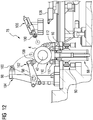
- eine Seitenansicht einer Beprobungsstation der Coilverarbeitungsanlage aus
FIG 10 ; - FIG 13
- eine Seitenansicht einer Umfangsumreifungsstation der Coilverarbeitungsanlage aus
FIG 10 ; - FIG 14
- eine Draufsicht einer anderen Coilverarbeitungsanlage.
- FIG. 1
- a side view of a first embodiment of a transport device and a resting on the transport device coils, in a state in which a coil support of the transport device is lowered;
- FIG. 2
- a side view of the transport device
FIG. 1 and a coil resting on the transport device, in a state in which the coil support is raised; - FIG. 3
- a frontal view of the transport device
FIG. 1 andFIG. 2 ; - FIG. 4
- a front view of a second embodiment of a transport device for transporting a coil;
- FIG. 5
- a side view of the transport device
FIG. 4 ; - FIG. 6
- a side view of a third embodiment of a transport device and a resting on the transport device coils, in a state in which a clamping unit of the transport device is sunk in the coil support;
- FIG. 7
- a plan view of the transport device
FIG. 6 and a coil resting on the transport device; - FIG. 8
- a 3D view of a possible embodiment variant of a coil support and a clamping unit for a transport device for transporting a coil;
- FIG. 9
- a 3D view of a possible design variant of a chassis for a transport device for transporting a coil;
- FIG. 10
- a plan view of a coil processing plant;
- FIG. 11
- a side view of a strip removal station of the coil processing plant
FIG. 10 ; - FIG. 12
- a side view of a sampling station of the coil processing plant
FIG. 10 ; - FIG. 13
- a side view of a circumferential strapping station of the coil processing plant
FIG. 10 ; - FIG. 14
- a top view of another coil processing plant.
Die Transportvorrichtung 2 umfasst einen Coiltransportwagen 6 mit einem Fahrgestell 8 und einer Coilauflage 10. Zudem umfasst die Transportvorrichtung 2 eine Fixiervorrichtung 12.The
Der Coiltransportwagen 6 umfasst vier rotierbar gelagerte Räder 14, die am Fahrgestell 8 des Coiltransportwagens 6 montiert sind. Mittels dieser Räder 14 ist der Coiltransportwagen 6 auf einer Schienenbahn verfahrbar.The
Die zuvor erwähnte Coilauflage 10 ist mit einer Mehrzahl von Auflagezinken 16 ausgestattet. Wie aus
Besagte Fixiervorrichtung 12 umfasst eine Klemmeinheit zum Anpressen des zu transportierenden Coils 4 gegen die Coilauflage 10. Die Klemmeinheit 22 weist einen Klemmabschnitt 24 auf, welcher parallel zu Längsrichtung 20 der Coilauflage 10 ausgerichtet ist. Zudem umfasst die Klemmeinheit 22 einen mit dem Klemmabschnitt 24 verbundenen Basisabschnitt 26 sowie einen mit dem Klemmabschnitt 24 verbundenen Gleitabschnitt 28. Sowohl der Basisabschnitt 26 als auch der Gleitabschnitt 28 sind senkrecht zum Klemmabschnitt 24 der Klemmeinheit 22 ausgerichtet.Said fixing
Die Coilauflage 10 ist gegenüber dem Fahrgestell 8 höhenverstellbar. Mit anderen Worten, die Höhenposition der Coilauflage 10 kann relativ zum Fahrgestell 8 verstellt werden.The
Ferner verfügt der Coiltransportwagen 6 über eine Antriebseinheit 30 zum Anheben und Absenken der Coilauflage 10. Im vorliegenden Ausführungsbeispiel ist diese Antriebseinheit 30 als hydraulischer Hubzylinder ausgeführt, welcher eine Hubstange 32 aufweist (vgl.
Des Weiteren ist die Klemmeinheit 22 gegenüber der Coilauflage 10 höhenverstellbar. D. h., die Höhenposition der Klemmeinheit 22 kann relativ zur Coilauflage 10 verstellt werden.Furthermore, the clamping
Die Fixiervorrichtung 12 umfasst eine Antriebseinheit 34 zum Anheben und Absenken der Klemmeinheit 22. Auch diese Antriebseinheit 34 ist als hydraulischer Hubzylinder mit einer Hubstange 36 ausgebildet. Ferner ist die Antriebseinheit 34 der Fixiervorrichtung 12, genauer gesagt, deren Hubstange 36, in den Basisabschnitt 26 der Klemmeinheit 22 integriert. Um die Klemmeinheit 22 relativ zur Coilauflage 10 anzuheben, wird die Hubstange 36 der Antriebseinheit 34 der Fixiervorrichtung 12 ausgefahren. Umgekehrt wird, um die Klemmeinheit 22 relativ zur Coilauflage 10 abzusenken, die Hubstange 36 dieser Antriebseinheit 34 eingefahren.The fixing
Im vorliegenden Ausführungsbeispiel ist die Fixiervorrichtung 12, genauer gesagt ihre Antriebseinheit 34, an der Coilauflage 10 befestigt. Außerdem weist die Coilauflage 10 eine Gleitführung 38 auf, durch welche der zuvor erwähnte Gleitabschnitt 28 der Klemmeinheit 22 geführt ist und mittels welcher die Klemmeinheit 22 linear verschiebbar gelagert ist.In the present embodiment, the fixing
Des Weiteren weist die Coilauflage 10 eine Aussparung 40 auf, in welcher der Klemmabschnitt 24 der Klemmeinheit 22 versenkbar ist, falls eine Anpressung des Coils 4 gegen die Coilauflage 10 nicht erforderlich ist.Furthermore, the
In
Auch in dieser Abbildung liegt ein zu transportierendes Coil 4 auf der Coilauflage 10 der Transportvorrichtung 2 auf. Zudem ist die Klemmeinheit 22 in ein Coilauge 42 des zu transportierenden Coils 4 eingeführt und drückt diesen gegen die Coilauflage 10 der Transportvorrichtung 2.Also in this figure is a
Im Vergleich zu dem in
Aus
Des Weiteren ist aus
Die Beschreibungen der nachfolgenden Ausführungsbeispiele beschränken sich jeweils primär auf die Unterschiede zu dem vorhergehenden Ausführungsbeispiel, auf das bezüglich gleichbleibender Merkmale und Funktionen verwiesen wird. Im Wesentlichen gleiche und/oder einander entsprechende Elemente sind, soweit zweckdienlich, mit den gleichen Bezugszeichen bezeichnet und nicht erwähnte Merkmale sind in den nachfolgenden Ausführungsbeispielen übernommen, ohne dass sie erneut beschrieben werden.The descriptions of the following exemplary embodiments are each limited primarily to the differences from the previous exemplary embodiment, to which reference is made with regard to features and functions that remain the same. Essentially identical and / or corresponding elements are, as far as appropriate, designated by the same reference numerals and features not mentioned are taken over in the following exemplary embodiments without being described again.
Die Klemmeinheit 22 dieser Transportvorrichtung 50 ist mit einer Reibungsverringerungseinheit 52 ausgestattet. Die Reibungsverringerungseinheit 52 dient dazu, einen Reibungswiderstand zwischen einem zu transportierenden Coil und der Klemmeinheit 22 zu verringern, wenn das Coil auf der Coilauflage 10 aufliegend gedreht werden soll und dabei die Klemmeinheit 22 gegen das Coil drückt. Ein Drehen eines auf der Coilauflage 10 aufliegenden Coils kann zum Beispiel beim Auf- und/oder Abwickeln des Coils erfolgen, insbesondere im Rahmen einer Beprobung des Coils.The clamping
Im vorliegenden Ausführungsbeispiel umfasst die Reibungsverringerungseinheit 52 mehrere drehbar gelagerte Rollen 54 als Reibungsverringerungsmittel. Diese Rollen 54 sind an der Unterseite 46 des Klemmabschnitts 24 der Klemmeinheit 22 angeordnet.In the present embodiment, the
Aus
Bei dieser Transportvorrichtung 56 ist die Fixiervorrichtung 12, insbesondere deren Antriebseinheit 34, nicht an der Coilauflage 10, sondern an dem Fahrgestell 8 des Coiltransportwagens 6 montiert. Zudem weist die Coilauflage 10 keine Gleitführung für die Klemmeinheit 22 auf. Stattdessen verfügt das Fahrgestell 8 über eine Gleitführung 58 für die Klemmeinheit 22.In this
Der Basisabschnitt 26 der Klemmeinheit 22 ist durch die Gleitführung 58 des Fahrgestells 8 geführt und mithilfe dieser Gleitführung 58 linear verschiebbar gelagert. Bei der Transportvorrichtung 56 aus
Zudem weist die Transportvorrichtung 56 aus
In dem in
Außerdem erstreckt sich die Breite 64 des zu transportierenden Coils 4 im vorliegenden Ausführungsbeispiel im Wesentlichen über die gesamte Länge der Coilauflage 10.In addition, in the present exemplary embodiment, the
Die Coilauflage 10 verfügt über einen Gleitabschnitt 66, welcher in eine Gleitführung eines Fahrgestells einsetzbar ist.The
Außerdem weist die Coilauflage 10 eine Gleitführung 38 auf. Die Klemmeinheit 22, genauer gesagt dessen Basisabschnitt 26, ist durch diese Gleitführung 38 geführt, und mittels der Gleitführung 38 linear verschiebbar gelagert.In addition, the
Bei der Klemmeinheit 22 aus
Ferner ist in
Das Fahrgestell 8 umfasst eine Gleitführung 68 zum Führen einer Coilauflage. Diese Gleitführung 68 ist insbesondere dazu eingerichtet, einen Gleitabschnitt einer Coilauflage, wie zum Beispiel den Gleitabschnitt 66 der Coilauflage 10 aus
Des Weiteren sind an dem Fahrgestell 8 vier rotierbar gelagerte Räder 14 montiert, mittels welcher das Fahrgestell 8 auf einer Schienenbahn verfahren werden kann. In
Diese Coilverarbeitungsanlage 70 umfasst acht Coilverarbeitungsstationen 72-86. Grundsätzlich sind auch Ausführungen der Coilverarbeitungsanlage 70 möglich, bei denen die Coilverarbeitungsanlage 70 eine andere Anzahl von Coilverarbeitungsstationen aufweist.This
Im vorliegenden Ausführungsbeispiel handelt es bei den Coilverarbeitungsstationen 72-86 um eine erste Abgabestation 72, eine zweite Abgabestation 74, eine Bandentfernungsstation 76, eine Beprobungsstation 78, eine Umfangsumreifungsstation 80, eine Wiegestation 82, eine Augenumreifungsstation 84 und eine Abholstation 86. Die einzelnen Coilverarbeitungsstationen 72-86 müssen nicht notwendigerweise in der in
Des Weiteren umfasst die Coilverarbeitungsanlage 70 eine (in
In
Nachfolgend wird für ein einzelnes Coil 4 exemplarisch beschrieben, wie dieses Coil 4 in der Coilverarbeitungsanlage 70 verarbeitet wird. Es wird davon ausgegangen, dass dieses Coil 4 mit einer Umfangsumreifung, also mit einem sich um den Außenumfang des Coil 4 erstreckenden Bindeband, verschlossen ist.In the following, it will be described by way of example for a
Das Coil 4 wird mithilfe eines (figürlich nicht dargestellten) Transportsystems, wie zum Beispiel eines Krans, zur Coilverarbeitungsanlage 70 transportiert und an der ersten oder zweiten Abgabestation 72, 74 abgelegt.The
Mittels der zuvor erwähnten Transportvorrichtung 88 der Coilverarbeitungsanlage 70 wird das Coil 4 in der nachfolgend beschriebenen Weise von der ersten bzw. zweiten Abgabestation 72, 74 zur Bandentfernungsstation 76 transportiert.By means of the
Zunächst wird die Höhenposition der Klemmeinheit 22 der Transportvorrichtung 88 derart eingestellt, dass die Klemmeinheit 22 bei einer horizontalen Verschiebung des Coiltransportwagens 6 in ein Coilauge 42 des Coils 4 einführbar ist.First, the height position of the clamping
Der Coiltransportwagen 6 der Transportvorrichtung 88 wird an das in der ersten bzw. zweiten Abgabestation 72, 74 befindliche Coil 4 herangefahren und dabei die Klemmeinheit 22 der Transportvorrichtung 88 in das Coilauge 42 des Coils 4 eingeführt.The
Die in das Coilauge 42 eingeführte Klemmeinheit 22 wird abgesenkt, bis die Klemmeinheit 22 gegen das Coil 4 drückt. Dann wird die Coilauflage 10 der Transportvorrichtung 88 angehoben, bis das Coil 4 auf der Coilauflage 10 aufliegt. Die Höhenposition der Klemmeinheit 22 wird hierbei nicht verändert. Anschließend werden die Coilauflage 10 und die Klemmeinheit 22 synchron angehoben.The clamping
Dann wird das Coil 4 auf der Coilauflage 10 aufliegend mithilfe des Coiltransportwagens 6 zu der Bandentfernungsstation 76 transportiert, wobei das Coil 4 während des Transports von der Klemmeinheit 22 gegen die Coilauflage 10 gedrückt wird.Then, the
Wenn das Coil 4 die Bandentfernungsstation 76 erreicht hat, werden die Coilauflage 10 und die Klemmeinheit 22 synchron abgesenkt werden, bis das Coil 4 auf einer Coilaufnahme 92 der Bandentfernungsstation 76 aufliegt (vgl.
In der Bandentfernungsstation 76 wird die Umfangsumreifung des Coils 4 entfernt.In the
Anschließend wird das Coil 4 mittels der Transportvorrichtung 88 von der Bandentfernungsstation 76 zu der Beprobungsstation 78 transportiert. In der Beprobungsstation 78 wird von dem Coil 4 eine Probe entnommen.Subsequently, the
Dann wird das Coil 4 mittels der Transportvorrichtung 88 von der Beprobungsstation 78 zu der Umfangsumreifungsstation 80 transportiert. Dort erhält das Coil 4 eine Umfangsumreifung.Then, the
Danach wird das Coil 4 von der Umfangsumreifungsstation 80 zu der Wiegestation 82 transportiert, wo das Coil 4 gewogen wird.Thereafter, the
Nach dem Wiegen wird das Coil 4 mittels der Transportvorrichtung 88 von der Wiegestation 82 zur Augenumreifungsstation 84 transportiert, wo das Coil 4 eine Umreifung durch sein Coilauge 42 erhält.After weighing, the
Anschließend wird das Coil 4 mittels der Transportvorrichtung 88 von der Augenumreifungsstation 84 zur Abholstation 86 transportiert. Dort wird das Coil 4 mithilfe eines (figürlich nicht dargestellten) Transportsystems, wie zum Beispiel eines Krans, von der Coilverarbeitungsanlage 70 abtransportiert.Subsequently, the
Der Transport des Coils 4 von einer der Coilverarbeitungsstationen 72-86 zur jeweils nächsten Coilverarbeitungsstation 72-86 erfolgt in der gleichen Weise wie weiter oben beim Transport von der ersten bzw. zweiten Abgabestation 72, 74 zur Bandentfernungsstation 76 beschrieben.The transport of the
Die Bandentfernungsstation 76 umfasst eine Bandentfernungsvorrichtung 94 zum Entfernen eines Umreifungsbands von dem Coil 4. Außerdem weist die Bandentfernungsstation 76 im vorliegenden Beispiel eine Niederhaltevorrichtung 96 auf, welche einen Schwenkarm 98 mit einer am Schwenkarm 98 befestigten Niederhalterolle 100 umfasst.The
In
Ferner wird in
Die Beprobungsstation 78 umfasst eine erste Niederhaltevorrichtung 102 sowie eine zweite Niederhaltevorrichtung 104, die jeweils einen Schwenkarm 98 sowie eine an dem Schwenkarm 98 befestigte Niederhalterolle 100 aufweisen. Außerdem weist die Beprobungsstation 78 eine dritte Niederhaltevorrichtung 106 auf, welche mit einer linear verschiebbaren Niederhalterolle 100 ausgestattet ist.The
Des Weiteren umfasst die Beprobungsstation 78 eine verfahrbare Trennvorrichtung 108 zum Abtrennen einer Probe von einem Coil 4. Im vorliegenden Ausführungsbeispiel ist die Trennvorrichtung 108 als Plasmaschneider ausgebildet.Furthermore, the
Ferner ist in
In
Die Coilauflage 10 der Transportvorrichtung 88 ist in
Des Weiteren ist die Klemmeinheit 22 der Transportvorrichtung 88 in
Die Umfangsumreifungsstation 80 umfasst eine Umreifungsvorrichtung 114 zum Umreifen eines Coils 4 an dessen Außenumfang. Darüber hinaus weist die Umfangsumreifungsstation 80 eine Coilaufnahme 116 auf.The circumferential strapping
In
Ist eine Anpressung eines zu transportierenden Coils gegen die Coilauflage 10 der Transportvorrichtung 88 nicht erforderlich, kann die Klemmeinheit 22 in der Coilauflage 10 versenkt werden (oder versenkt bleiben) und das Coil im versenkten Zustand der Klemmeinheit 22 auf der Coilauflage 10 aufliegend von einer der Coilverarbeitungsstationen 72-86 zu einer der anderen Coilverarbeitungsstationen 72-86 transportiert werden.Is a contact pressure of a coil to be transported against the
Falls an der ersten oder zweiten Abgabestation 72, 74 ein Coil abgelegt wird, das in Coilverarbeitungsanlage 70 nicht beprobt, sondern lediglich umreift und ggf. gewogen werden soll, kann das Coil von der ersten bzw. zweiten Abgabestation 72, 74 mittels der Transportvorrichtung 88 direkt zu der Umfangsumreifungsstation 80 oder der Augenumreifungsstation 84 transportiert werden.If a coil is deposited at the first or
Ferner ist es möglich, dass ein Coil, welches nicht mit einem oder mehreren Umreifungsbändern verschlossen ist, in die Coilverarbeitungsanlage 70 eingebracht wird, um beprobt zu werden. In diesem Fall kann das Coil von der ersten bzw. zweiten Abgabestation 72, 74 mittels der Transportvorrichtung 88 direkt zu der Beprobungsstation 78, also ohne Zwischenstopp bei der Bandentfernungsstation 76, transportiert werden.Furthermore, it is possible that a coil which is not closed with one or more strapping bands, is introduced into the
Außerdem ist möglich, dass die Coilverarbeitungsanlage 70 mehrere Transportvorrichtungen der zuvor beschriebenen Art aufweist. Diese können in unterschiedlichen Bereichen der Coilverarbeitungsanlage 70 eingesetzt werden. Beispielsweise kann die zuvor erwähnte Transportvorrichtung 88 für den Transport eines Coils von der ersten Abgabestation 72 bis zur Beprobungsstation 78 eingesetzt werden, während eine zusätzliche Transportvorrichtung für den Transport desselben Coils von der Beprobungsstation 78 bis zur Abholstation 86 eingesetzt werden kann.It is also possible that the
Diese Coilverarbeitungsanlage 118 umfasst vier Coilverarbeitungsstationen 72, 76, 78, 80. Im vorliegenden Ausführungsbeispiel handelt es bei den Coilverarbeitungsstationen 72, 76, 78, 80 um eine Abgabestation 72, eine Bandentfernungsstation 76, eine Umfangsumreifungsstation 80 und eine Beprobungsstation 78. Die einzelnen Coilverarbeitungsstationen 72, 76, 78, 80 müssen nicht notwendigerweise in der in
Des Weiteren umfasst die Coilverarbeitungsanlage 118 eine (in
Mithilfe eines (figürlich nicht dargestellten) Transportsystems, wie zum Beispiel eines Krans, wird ein in der Coilverarbeitungsanlage 118 zu verarbeitendes Coil 4 zur Abgabestation 72 transportiert und dort abgelegt.By means of a (not shown figuratively) transport system, such as a crane, a to be processed in the
Mittels der Transportvorrichtung der Coilverarbeitungsanlage 118 wird das Coil 4 gemäß der weiter oben im Zusammenhang mit
Nach seiner Beprobung in der Beprobungsstation 78 wird das Coil 4 mittels der Transportvorrichtung der Coilverarbeitungsanlage 118 in die umgekehrte Richtung von der Beprobungsstation 78 zu der Umreifungsstation 80 transportiert, wo das Coil 4 umreift wird.After its sampling in the
Von der Umreifungsstation 80 wird das Coil 4 mittels der Transportvorrichtung der Coilverarbeitungsanlage 118 zur Abgabestation 72 transportiert. Dort wird das Coil 4 mithilfe des zuvor erwähnten Transportsystems aus der Coilverarbeitungsanlage 118 abtransportiert. Die Abgabestation 72 dient somit zugleich als Abholstation der Coilverarbeitungsanlage 118.From the strapping
Prinzipiell kann die Beprobungsstation 78 mit einer eigenen Bandentfernungsvorrichtung ausgestattet sein. In solch einem Fall, könnte auf die Bandentfernungsstation 76 der Coilverarbeitungsanlage 118 grundsätzlich verzichtet werden.In principle, the
Obwohl die Erfindung im Detail durch die bevorzugten Ausführungsbeispiele näher illustriert und beschrieben wurde, so ist die Erfindung nicht durch die offenbarten Beispiele eingeschränkt und andere Variationen können hieraus abgeleitet werden, ohne den Schutzumfang der Erfindung zu verlassen.Although the invention has been further illustrated and described in detail by the preferred embodiments, the invention is not limited by the disclosed examples and other variations can be derived therefrom without departing from the scope of the invention.
- 22
- Transportvorrichtungtransport device
- 44
- Coilcoil
- 66
- Coiltransportwagencoil transport
- 88th
- Fahrgestellchassis
- 1010
- CoilauflageCoilauflage
- 1212
- Fixiervorrichtungfixing
- 1414
- Radwheel
- 1616
- Auflagezinkenedition tines
- 1818
- Coilachsecoil axis
- 2020
- Längsrichtunglongitudinal direction
- 2222
- Klemmeinheitterminal unit
- 2424
- Klemmabschnittclamping section
- 2626
- Basisabschnittbase section
- 2828
- Gleitabschnittsliding
- 3030
- Antriebseinheitdrive unit
- 3232
- Hubstangelifting rod
- 3434
- Antriebseinheitdrive unit
- 3636
- Hubstangelifting rod
- 3838
- Gleitführungslide
- 4040
- Aussparungrecess
- 4242
- Coilaugecoil eye
- 4444
- Anpressflächepressing surface
- 4646
- Unterseitebottom
- 4848
- LängsmittelebeneLongitudinal center plane
- 5050
- Transportvorrichtungtransport device
- 5252
- ReibungsverringerungseinheitFriction reduction unit
- 5454
- Rollerole
- 5656
- Transportvorrichtungtransport device
- 5858
- Gleitführungslide
- 6060
- Oberseitetop
- 6262
- Oberseitetop
- 6464
- Breitewidth
- 6666
- Gleitabschnittsliding
- 6868
- Gleitführungslide
- 7070
- CoilverarbeitungsanlageCoilverarbeitungsanlage
- 7272
- Abgabestationdispensing station
- 7474
- Abgabestationdispensing station
- 7676
- BandentfernungsstationBand removal station
- 7878
- Beprobungsstationsampling station
- 8080
- UmfangsumreifungsstationUmfangsumreifungsstation
- 8282
- WiegestationWeighing station
- 8484
- AugenumreifungsstationAugenumreifungsstation
- 8686
- Abholstationpick-up location
- 8888
- Transportvorrichtungtransport device
- 9090
- Schienenbahnrail track
- 9292
- CoilaufnahmeCoilaufnahme
- 9494
- BandentfernungsvorrichtungBand removing device
- 9696
- NiederhaltevorrichtungHold-down device
- 9898
- Schwenkarmswivel arm
- 100100
- NiederhalterolleDown roller
- 102102
- NiederhaltevorrichtungHold-down device
- 104104
- NiederhaltevorrichtungHold-down device
- 106106
- NiederhaltevorrichtungHold-down device
- 108108
- Trennvorrichtungseparating device
- 110110
- CoilaufnahmeCoilaufnahme
- 112112
- Bodenrollebottom roller
- 114114
- Umreifungsvorrichtungstrapper
- 116116
- CoilaufnahmeCoilaufnahme
- 118118
- CoilverarbeitungsanlageCoilverarbeitungsanlage
Claims (15)
dadurch gekennzeichnet, dass die Coilauflage (10) eine Aussparung (40) aufweist, in welcher die Klemmeinheit (22) zumindest teilweise versenkbar ist.Transport device (2, 50, 56, 88) according to claim 1 or 2,
characterized in that the coil support (10) has a recess (40) in which the clamping unit (22) is at least partially retractable.
dadurch gekennzeichnet, dass die Klemmeinheit (22) mit einer Reibungsverringerungseinheit (52) zur Verringerung eines Reibungswiderstands zwischen dem Coil (4) und der Klemmeinheit (22) beim Auf- und/oder Abwickeln des Coils (4) ausgestattet ist.Transport device (2, 50, 56, 88) according to one of the preceding claims,
characterized in that the clamping unit (22) is provided with a friction reducing unit (52) for reducing frictional resistance between the coil (4) and the clamping unit (22) during winding and / or unwinding of the coil (4).
dadurch gekennzeichnet, dass die Klemmeinheit (22) eine abgerundete Anpressfläche (44) zum Anpressen an das Coilauge (42) aufweist.Transport device (2, 50, 56, 88) according to one of the preceding claims,
characterized in that the clamping unit (22) has a rounded contact surface (44) for pressing against the coil eye (42).
dadurch gekennzeichnet, dass die Coilauflage (10) mehrere Auflagezinken (16) aufweist, auf welchen das Coil (4) auflegbar ist, wobei die Auflagezinken (16) zur Längsmittelebene (48) der Coilauflage (10) hin abgeschrägt sind.Transport device (2, 50, 56, 88) according to one of the preceding claims,
characterized in that the coil support (10) a plurality of support tines (16) on which the coil (4) can be placed, wherein the support tines (16) to the longitudinal center plane (48) of the coil support (10) are beveled.
dadurch gekennzeichnet, dass beim Transport des Coils (4)
characterized in that during transport of the coil (4)
dadurch gekennzeichnet, dass, wenn das Coil (4) die zweite Coilverarbeitungsstation (72-86) erreicht hat, die Coilauflage (10) und die Klemmeinheit (22) synchron abgesenkt werden, bis das Coil (4) auf einer Coilaufnahme (92, 110, 116) der zweiten Coilverarbeitungsstation (72-86) aufliegt, und dann die Coilauflage (10) abgesenkt wird, wobei das Coil (4) beim Absenken der Coilauflage (10) von der Klemmeinheit(22) gegen die Coilaufnahme (92, 110, 116) der zweiten Coilverarbeitungsstation (72-86) gedrückt wird.Method according to claim 12,
characterized in that , when the coil (4) has reached the second coil processing station (72-86), the coil support (10) and the clamping unit (22) are lowered synchronously until the coil (4) is mounted on a coil receiver (92, 110 , 116) of the second coil processing station (72-86), and then the coil support (10) is lowered, wherein the coil (4) upon lowering of the coil support (10) from the clamping unit (22) against the coil receptacle (92, 110, 116) of the second coil processing station (72-86).
dadurch gekennzeichnet, dass, während sich das Coil (4) in/an der ersten Coilverarbeitungsstation (72-86) befindet, eine gegen das Coil (4) drückende Niederhaltevorrichtung (96, 102-106) der ersten Coilverarbeitungsstation (72-86) von dem Coil (4) entfernt wird, wenn die Klemmeinheit (22) gegen das Coil (4) drückt.Method according to claim 12 or 13,
characterized in that , while the coil (4) is in / at the first coil processing station (72-86), a holddown device (96, 102-106) of the first coil processing station (72-86) of FIG the coil (4) is removed when the clamping unit (22) presses against the coil (4).
dadurch gekennzeichnet, dass, wenn das Coil (4) die zweite Coilverarbeitungsstation (72-86) erreicht hat, die Klemmeinheit (22) erst dann von dem Coil (4) abgehoben wird, wenn eine Niederhaltevorrichtung (96, 102-106) der zweiten Coilverarbeitungsstation (72-86) gegen das Coil (4) drückt.Method according to one of claims 12 to 14,
characterized in that , when the coil (4) has reached the second coil processing station (72-86), the clamping unit (22) is lifted off the coil (4) only when a hold-down device (96, 102-106) of the second Coil processing station (72-86) presses against the coil (4).
Priority Applications (8)
| Application Number | Priority Date | Filing Date | Title |
|---|---|---|---|
| EP17157294.4A EP3366381A1 (en) | 2017-02-22 | 2017-02-22 | Device and method for transporting a coil |
| EP18705420.0A EP3585529B1 (en) | 2017-02-22 | 2018-02-22 | Device and method for transporting a coil |
| RU2019126630A RU2752617C2 (en) | 2017-02-22 | 2018-02-22 | Transporting apparatus and method for transporting a strip metal roll |
| MX2019009892A MX2019009892A (en) | 2017-02-22 | 2018-02-22 | Transport device and method for transporting a coil. |
| CN201880013460.4A CN110300634B (en) | 2017-02-22 | 2018-02-22 | Conveying device and method for conveying a web |
| PCT/EP2018/054378 WO2018153982A1 (en) | 2017-02-22 | 2018-02-22 | Transport device and method for transporting a coil |
| US16/483,173 US11273480B2 (en) | 2017-02-22 | 2018-02-22 | Transport device and method for transporting a coil |
| JP2019545765A JP6855591B2 (en) | 2017-02-22 | 2018-02-22 | Methods for transporting transport devices and coils |
Applications Claiming Priority (1)
| Application Number | Priority Date | Filing Date | Title |
|---|---|---|---|
| EP17157294.4A EP3366381A1 (en) | 2017-02-22 | 2017-02-22 | Device and method for transporting a coil |
Publications (1)
| Publication Number | Publication Date |
|---|---|
| EP3366381A1 true EP3366381A1 (en) | 2018-08-29 |
Family
ID=58162455
Family Applications (2)
| Application Number | Title | Priority Date | Filing Date |
|---|---|---|---|
| EP17157294.4A Withdrawn EP3366381A1 (en) | 2017-02-22 | 2017-02-22 | Device and method for transporting a coil |
| EP18705420.0A Active EP3585529B1 (en) | 2017-02-22 | 2018-02-22 | Device and method for transporting a coil |
Family Applications After (1)
| Application Number | Title | Priority Date | Filing Date |
|---|---|---|---|
| EP18705420.0A Active EP3585529B1 (en) | 2017-02-22 | 2018-02-22 | Device and method for transporting a coil |
Country Status (7)
| Country | Link |
|---|---|
| US (1) | US11273480B2 (en) |
| EP (2) | EP3366381A1 (en) |
| JP (1) | JP6855591B2 (en) |
| CN (1) | CN110300634B (en) |
| MX (1) | MX2019009892A (en) |
| RU (1) | RU2752617C2 (en) |
| WO (1) | WO2018153982A1 (en) |
Cited By (1)
| Publication number | Priority date | Publication date | Assignee | Title |
|---|---|---|---|---|
| EP4067274A1 (en) | 2021-03-31 | 2022-10-05 | Primetals Technologies Austria GmbH | Secure handling of sleeves or metal collars having a small external diameter on a mandrel |
Families Citing this family (1)
| Publication number | Priority date | Publication date | Assignee | Title |
|---|---|---|---|---|
| EP3795483A1 (en) * | 2019-09-19 | 2021-03-24 | Primetals Technologies Germany GmbH | Automated removal of binding strips from a coil |
Citations (8)
| Publication number | Priority date | Publication date | Assignee | Title |
|---|---|---|---|---|
| JPS54152134U (en) * | 1978-04-12 | 1979-10-23 | ||
| JPH03193215A (en) * | 1989-12-22 | 1991-08-23 | Kawasaki Steel Corp | Scrap coil transferring method on strip aligning line |
| JPH0385106U (en) * | 1989-12-20 | 1991-08-28 | ||
| JPH0725525A (en) * | 1993-07-06 | 1995-01-27 | Nippon Steel Corp | Method and device for carrying out strip coil |
| JPH0788551A (en) * | 1993-09-20 | 1995-04-04 | Nippon Steel Corp | Coil body take out device |
| JP2007044747A (en) * | 2005-08-11 | 2007-02-22 | Nippon Steel Corp | Steel strip coil inside diameter holding device |
| JP2011020761A (en) * | 2009-07-14 | 2011-02-03 | Mitsubishi-Hitachi Metals Machinery Inc | Coil carrying device and coil station using the same |
| DE102011080410A1 (en) * | 2010-12-10 | 2012-06-14 | Sms Siemag Ag | Apparatus and method for handling a metal strip |
Family Cites Families (23)
| Publication number | Priority date | Publication date | Assignee | Title |
|---|---|---|---|---|
| US2198644A (en) * | 1937-11-04 | 1940-04-30 | Frank L Wettengel | Coil handling device |
| US2981429A (en) * | 1959-03-26 | 1961-04-25 | Clark Equipment Co | Paper roll handling truck |
| JPS5137862A (en) | 1974-09-27 | 1976-03-30 | Nippon Kokan Kk | KOIRUSEISEISHOTSUPU |
| US4056186A (en) * | 1975-04-21 | 1977-11-01 | Morgan Construction Company | Coil handling apparatus and system |
| JPS54116361A (en) * | 1978-03-03 | 1979-09-10 | Hitachi Ltd | Band treater |
| SU1007779A1 (en) * | 1981-04-24 | 1983-03-30 | Предприятие П/Я В-2869 | Apparatus for coiling/uncoiling metallic strips |
| JPS59106617A (en) | 1982-12-07 | 1984-06-20 | Taisei Corp | Curtain grout work |
| JPS59106617U (en) | 1982-12-28 | 1984-07-18 | 石川島播磨重工業株式会社 | Coil car with coil fall prevention device |
| US4657196A (en) * | 1984-09-04 | 1987-04-14 | Aluminum Company Of America | Mechanism for supporting and rotating a coil |
| JPS6384727A (en) * | 1986-09-29 | 1988-04-15 | Sumitomo Metal Ind Ltd | Collection device for test piece of coil stock |
| CH679993A5 (en) * | 1987-03-06 | 1992-05-29 | Ferag Ag | |
| JPS63168224U (en) | 1987-04-24 | 1988-11-01 | ||
| CH684267A5 (en) | 1990-03-23 | 1994-08-15 | Ferag Ag | Means for unwinding flexible planar formations from a roll. |
| JPH0811650B2 (en) * | 1991-07-04 | 1996-02-07 | 株式会社小林搬送機器 | Coiled material transfer vehicle |
| JPH072220A (en) * | 1993-06-16 | 1995-01-06 | Nippon Steel Corp | Coil packing/processing device being combined with unmanned carrying truck |
| GB9510822D0 (en) | 1995-05-23 | 1995-07-19 | Rieter Scragg Ltd | Package transfer arrangement |
| US5706692A (en) * | 1996-03-06 | 1998-01-13 | Tapco International Corporation | Combined portable sheet bending brake, coil holder and cut-off mechanism |
| IT1308255B1 (en) * | 1999-03-22 | 2001-12-10 | Perini Fabio Spa | DEVICE AND METHOD FOR UNWINDING SPOOLS OF MATERIALS |
| JP2001058761A (en) | 1999-06-08 | 2001-03-06 | Bridgestone Corp | Storing method and device for long member of plastic deformation |
| US6290164B1 (en) * | 2000-03-01 | 2001-09-18 | Kt Equipment (International) Inc. | Method and apparatus for supplying strip material |
| US20040050988A1 (en) | 2002-09-12 | 2004-03-18 | Kt Industries Llc | Method and apparatus for packing material under compression and the package made thereby |
| RU2338612C1 (en) * | 2007-02-05 | 2008-11-20 | Открытое акционерное общество "Электростальский завод тяжелого машиностроения" | Device for removing rolls from accumulator and to place them on unwinder |
| CN104923584B (en) | 2014-03-20 | 2017-07-28 | 宝山钢铁股份有限公司 | A kind of coil stripping car |
-
2017
- 2017-02-22 EP EP17157294.4A patent/EP3366381A1/en not_active Withdrawn
-
2018
- 2018-02-22 RU RU2019126630A patent/RU2752617C2/en active
- 2018-02-22 EP EP18705420.0A patent/EP3585529B1/en active Active
- 2018-02-22 WO PCT/EP2018/054378 patent/WO2018153982A1/en active Application Filing
- 2018-02-22 CN CN201880013460.4A patent/CN110300634B/en active Active
- 2018-02-22 US US16/483,173 patent/US11273480B2/en active Active
- 2018-02-22 JP JP2019545765A patent/JP6855591B2/en active Active
- 2018-02-22 MX MX2019009892A patent/MX2019009892A/en unknown
Patent Citations (8)
| Publication number | Priority date | Publication date | Assignee | Title |
|---|---|---|---|---|
| JPS54152134U (en) * | 1978-04-12 | 1979-10-23 | ||
| JPH0385106U (en) * | 1989-12-20 | 1991-08-28 | ||
| JPH03193215A (en) * | 1989-12-22 | 1991-08-23 | Kawasaki Steel Corp | Scrap coil transferring method on strip aligning line |
| JPH0725525A (en) * | 1993-07-06 | 1995-01-27 | Nippon Steel Corp | Method and device for carrying out strip coil |
| JPH0788551A (en) * | 1993-09-20 | 1995-04-04 | Nippon Steel Corp | Coil body take out device |
| JP2007044747A (en) * | 2005-08-11 | 2007-02-22 | Nippon Steel Corp | Steel strip coil inside diameter holding device |
| JP2011020761A (en) * | 2009-07-14 | 2011-02-03 | Mitsubishi-Hitachi Metals Machinery Inc | Coil carrying device and coil station using the same |
| DE102011080410A1 (en) * | 2010-12-10 | 2012-06-14 | Sms Siemag Ag | Apparatus and method for handling a metal strip |
Cited By (2)
| Publication number | Priority date | Publication date | Assignee | Title |
|---|---|---|---|---|
| EP4067274A1 (en) | 2021-03-31 | 2022-10-05 | Primetals Technologies Austria GmbH | Secure handling of sleeves or metal collars having a small external diameter on a mandrel |
| WO2022207401A1 (en) | 2021-03-31 | 2022-10-06 | Primetals Technologies Austria GmbH | Reliable handling of sleeves or metal coils of small external diameter on a coiler mandrel |
Also Published As
| Publication number | Publication date |
|---|---|
| JP2020508876A (en) | 2020-03-26 |
| CN110300634B (en) | 2021-05-25 |
| EP3585529B1 (en) | 2023-04-05 |
| WO2018153982A1 (en) | 2018-08-30 |
| US11273480B2 (en) | 2022-03-15 |
| JP6855591B2 (en) | 2021-04-07 |
| RU2752617C2 (en) | 2021-07-29 |
| EP3585529A1 (en) | 2020-01-01 |
| MX2019009892A (en) | 2019-10-15 |
| US20200230676A1 (en) | 2020-07-23 |
| RU2019126630A3 (en) | 2021-06-01 |
| RU2019126630A (en) | 2021-03-23 |
| CN110300634A (en) | 2019-10-01 |
Similar Documents
| Publication | Publication Date | Title |
|---|---|---|
| EP2516081B1 (en) | Support for a metal coil and apparatuses comprising such a support | |
| EP2648860A1 (en) | Device and method for handling a metal strip | |
| EP3585529B1 (en) | Device and method for transporting a coil | |
| DE2558964A1 (en) | DEVICE FOR CONVEYING COILS OF STEEL STRIP TO AN UNWINDING STATION | |
| DE1237050B (en) | Continuously working multi-drum reel for stiff metal strip | |
| DE3619939A1 (en) | Process and device for the intermediate storage of printed products occurring in an imbricated formation | |
| EP3291926B1 (en) | System, coil transport vehicle and method for discharging a coil wound on a winding system | |
| DE2418316C2 (en) | Winding machine for sheet metal strips | |
| DE102010054142B4 (en) | Arrangement and method for removing at least one metal strip collar from a coiler mandrel of a take-up reel | |
| EP2829333B1 (en) | Tape reel arrangement for winding and/or unwinding a metal strip | |
| AT520228B1 (en) | Forage platform trailer | |
| DE2613237A1 (en) | Tracked transfer gantry for wire coils - has load arm attached to horizontal pivot shaft | |
| DE3109110C2 (en) | Device for the formation of wire rod coils | |
| DE4411366B4 (en) | Method for picking up and transporting a roll of wound strip material between two functional stations | |
| DE2212944A1 (en) | METHOD AND DEVICE FOR THE FORMATION OF ROLLED WIRE COILS | |
| DE202015105036U1 (en) | Handling of rollers, in particular axially juxtaposed rollers | |
| WO2019242920A1 (en) | Coiling a metal strip, and coiling system | |
| DE10017908C2 (en) | Method and coil binding machine for tying coil bundles lying on a table | |
| EP1413477B1 (en) | Method and device for changing skips | |
| EP4067274A1 (en) | Secure handling of sleeves or metal collars having a small external diameter on a mandrel | |
| DE4130417C2 (en) | Device for separating and pivoting narrow band bundles | |
| DE2246132C3 (en) | Device for forwarding rolling stock at the end of the cooling bed | |
| DE102017121556A1 (en) | Conveyor for converting pressed parts | |
| DE3826038A1 (en) | Apparatus for loading cylindrical articles | |
| DE3012207A1 (en) | DEVICE FOR REWINDING AND / OR UNWINDING PRODUCTS ON DRUM, IN PARTICULAR CABLES OR ROPES |
Legal Events
| Date | Code | Title | Description |
|---|---|---|---|
| PUAI | Public reference made under article 153(3) epc to a published international application that has entered the european phase |
Free format text: ORIGINAL CODE: 0009012 |
|
| STAA | Information on the status of an ep patent application or granted ep patent |
Free format text: STATUS: THE APPLICATION HAS BEEN PUBLISHED |
|
| AK | Designated contracting states |
Kind code of ref document: A1 Designated state(s): AL AT BE BG CH CY CZ DE DK EE ES FI FR GB GR HR HU IE IS IT LI LT LU LV MC MK MT NL NO PL PT RO RS SE SI SK SM TR |
|
| AX | Request for extension of the european patent |
Extension state: BA ME |
|
| STAA | Information on the status of an ep patent application or granted ep patent |
Free format text: STATUS: REQUEST FOR EXAMINATION WAS MADE |
|
| 17P | Request for examination filed |
Effective date: 20190228 |
|
| RBV | Designated contracting states (corrected) |
Designated state(s): AL AT BE BG CH CY CZ DE DK EE ES FI FR GB GR HR HU IE IS IT LI LT LU LV MC MK MT NL NO PL PT RO RS SE SI SK SM TR |
|
| STAA | Information on the status of an ep patent application or granted ep patent |
Free format text: STATUS: THE APPLICATION IS DEEMED TO BE WITHDRAWN |
|
| 18D | Application deemed to be withdrawn |
Effective date: 20190301 |