EP3365740B1 - Fahrzeug und verfahren zur erkennung einer fahrzeugposition auf der basis einer karte - Google Patents
Fahrzeug und verfahren zur erkennung einer fahrzeugposition auf der basis einer karte Download PDFInfo
- Publication number
- EP3365740B1 EP3365740B1 EP17747628.0A EP17747628A EP3365740B1 EP 3365740 B1 EP3365740 B1 EP 3365740B1 EP 17747628 A EP17747628 A EP 17747628A EP 3365740 B1 EP3365740 B1 EP 3365740B1
- Authority
- EP
- European Patent Office
- Prior art keywords
- map
- channel
- vehicle
- point cloud
- information
- Prior art date
- Legal status (The legal status is an assumption and is not a legal conclusion. Google has not performed a legal analysis and makes no representation as to the accuracy of the status listed.)
- Active
Links
Images


Classifications
-
- G—PHYSICS
- G01—MEASURING; TESTING
- G01S—RADIO DIRECTION-FINDING; RADIO NAVIGATION; DETERMINING DISTANCE OR VELOCITY BY USE OF RADIO WAVES; LOCATING OR PRESENCE-DETECTING BY USE OF THE REFLECTION OR RERADIATION OF RADIO WAVES; ANALOGOUS ARRANGEMENTS USING OTHER WAVES
- G01S17/00—Systems using the reflection or reradiation of electromagnetic waves other than radio waves, e.g. lidar systems
- G01S17/02—Systems using the reflection of electromagnetic waves other than radio waves
- G01S17/06—Systems determining position data of a target
- G01S17/42—Simultaneous measurement of distance and other co-ordinates
-
- G—PHYSICS
- G01—MEASURING; TESTING
- G01C—MEASURING DISTANCES, LEVELS OR BEARINGS; SURVEYING; NAVIGATION; GYROSCOPIC INSTRUMENTS; PHOTOGRAMMETRY OR VIDEOGRAMMETRY
- G01C21/00—Navigation; Navigational instruments not provided for in groups G01C1/00 - G01C19/00
- G01C21/26—Navigation; Navigational instruments not provided for in groups G01C1/00 - G01C19/00 specially adapted for navigation in a road network
- G01C21/28—Navigation; Navigational instruments not provided for in groups G01C1/00 - G01C19/00 specially adapted for navigation in a road network with correlation of data from several navigational instruments
- G01C21/30—Map- or contour-matching
-
- G—PHYSICS
- G01—MEASURING; TESTING
- G01S—RADIO DIRECTION-FINDING; RADIO NAVIGATION; DETERMINING DISTANCE OR VELOCITY BY USE OF RADIO WAVES; LOCATING OR PRESENCE-DETECTING BY USE OF THE REFLECTION OR RERADIATION OF RADIO WAVES; ANALOGOUS ARRANGEMENTS USING OTHER WAVES
- G01S17/00—Systems using the reflection or reradiation of electromagnetic waves other than radio waves, e.g. lidar systems
- G01S17/02—Systems using the reflection of electromagnetic waves other than radio waves
- G01S17/06—Systems determining position data of a target
-
- G—PHYSICS
- G01—MEASURING; TESTING
- G01S—RADIO DIRECTION-FINDING; RADIO NAVIGATION; DETERMINING DISTANCE OR VELOCITY BY USE OF RADIO WAVES; LOCATING OR PRESENCE-DETECTING BY USE OF THE REFLECTION OR RERADIATION OF RADIO WAVES; ANALOGOUS ARRANGEMENTS USING OTHER WAVES
- G01S17/00—Systems using the reflection or reradiation of electromagnetic waves other than radio waves, e.g. lidar systems
- G01S17/88—Lidar systems specially adapted for specific applications
- G01S17/89—Lidar systems specially adapted for specific applications for mapping or imaging
-
- G—PHYSICS
- G01—MEASURING; TESTING
- G01S—RADIO DIRECTION-FINDING; RADIO NAVIGATION; DETERMINING DISTANCE OR VELOCITY BY USE OF RADIO WAVES; LOCATING OR PRESENCE-DETECTING BY USE OF THE REFLECTION OR RERADIATION OF RADIO WAVES; ANALOGOUS ARRANGEMENTS USING OTHER WAVES
- G01S17/00—Systems using the reflection or reradiation of electromagnetic waves other than radio waves, e.g. lidar systems
- G01S17/88—Lidar systems specially adapted for specific applications
- G01S17/93—Lidar systems specially adapted for specific applications for anti-collision purposes
- G01S17/931—Lidar systems specially adapted for specific applications for anti-collision purposes of land vehicles
-
- G—PHYSICS
- G01—MEASURING; TESTING
- G01S—RADIO DIRECTION-FINDING; RADIO NAVIGATION; DETERMINING DISTANCE OR VELOCITY BY USE OF RADIO WAVES; LOCATING OR PRESENCE-DETECTING BY USE OF THE REFLECTION OR RERADIATION OF RADIO WAVES; ANALOGOUS ARRANGEMENTS USING OTHER WAVES
- G01S19/00—Satellite radio beacon positioning systems; Determining position, velocity or attitude using signals transmitted by such systems
- G01S19/38—Determining a navigation solution using signals transmitted by a satellite radio beacon positioning system
- G01S19/39—Determining a navigation solution using signals transmitted by a satellite radio beacon positioning system the satellite radio beacon positioning system transmitting time-stamped messages, e.g. GPS [Global Positioning System], GLONASS [Global Orbiting Navigation Satellite System] or GALILEO
- G01S19/42—Determining position
- G01S19/48—Determining position by combining or switching between position solutions derived from the satellite radio beacon positioning system and position solutions derived from a further system
- G01S19/485—Determining position by combining or switching between position solutions derived from the satellite radio beacon positioning system and position solutions derived from a further system whereby the further system is an optical system or imaging system
-
- G—PHYSICS
- G01—MEASURING; TESTING
- G01S—RADIO DIRECTION-FINDING; RADIO NAVIGATION; DETERMINING DISTANCE OR VELOCITY BY USE OF RADIO WAVES; LOCATING OR PRESENCE-DETECTING BY USE OF THE REFLECTION OR RERADIATION OF RADIO WAVES; ANALOGOUS ARRANGEMENTS USING OTHER WAVES
- G01S7/00—Details of systems according to groups G01S13/00, G01S15/00, G01S17/00
- G01S7/48—Details of systems according to groups G01S13/00, G01S15/00, G01S17/00 of systems according to group G01S17/00
- G01S7/4802—Details of systems according to groups G01S13/00, G01S15/00, G01S17/00 of systems according to group G01S17/00 using analysis of echo signal for target characterisation; Target signature; Target cross-section
-
- G—PHYSICS
- G01—MEASURING; TESTING
- G01S—RADIO DIRECTION-FINDING; RADIO NAVIGATION; DETERMINING DISTANCE OR VELOCITY BY USE OF RADIO WAVES; LOCATING OR PRESENCE-DETECTING BY USE OF THE REFLECTION OR RERADIATION OF RADIO WAVES; ANALOGOUS ARRANGEMENTS USING OTHER WAVES
- G01S7/00—Details of systems according to groups G01S13/00, G01S15/00, G01S17/00
- G01S7/48—Details of systems according to groups G01S13/00, G01S15/00, G01S17/00 of systems according to group G01S17/00
- G01S7/4808—Evaluating distance, position or velocity data
-
- G—PHYSICS
- G01—MEASURING; TESTING
- G01S—RADIO DIRECTION-FINDING; RADIO NAVIGATION; DETERMINING DISTANCE OR VELOCITY BY USE OF RADIO WAVES; LOCATING OR PRESENCE-DETECTING BY USE OF THE REFLECTION OR RERADIATION OF RADIO WAVES; ANALOGOUS ARRANGEMENTS USING OTHER WAVES
- G01S7/00—Details of systems according to groups G01S13/00, G01S15/00, G01S17/00
- G01S7/48—Details of systems according to groups G01S13/00, G01S15/00, G01S17/00 of systems according to group G01S17/00
- G01S7/481—Constructional features, e.g. arrangements of optical elements
- G01S7/4814—Constructional features, e.g. arrangements of optical elements of transmitters alone
- G01S7/4815—Constructional features, e.g. arrangements of optical elements of transmitters alone using multiple transmitters
-
- G—PHYSICS
- G01—MEASURING; TESTING
- G01S—RADIO DIRECTION-FINDING; RADIO NAVIGATION; DETERMINING DISTANCE OR VELOCITY BY USE OF RADIO WAVES; LOCATING OR PRESENCE-DETECTING BY USE OF THE REFLECTION OR RERADIATION OF RADIO WAVES; ANALOGOUS ARRANGEMENTS USING OTHER WAVES
- G01S17/00—Systems using the reflection or reradiation of electromagnetic waves other than radio waves, e.g. lidar systems
- G01S17/86—Combinations of lidar systems with systems other than lidar, radar or sonar, e.g. with direction finders
Definitions
- the present disclosure relates to a vehicle and a method of recognizing a position of a vehicle based on a map. More particularly, the present disclosure relates to a vehicle including a light detection and ranging (LiDAR) sensor and a method of recognizing a position of a vehicle based on a map.
- LiDAR light detection and ranging
- An autonomous driving vehicle refers to a vehicle that recognizes without driver intervention, determines a driving condition, and controls the vehicle to autonomously drive to a given destination. Recently, the autonomous driving vehicle has decreased the number of traffic accidents, enhanced transportation efficiency, saved fuel, and done driving instead and, thus, has attracted attention as individual transportation for enhancing convenience.
- a technology for recognizing a driving environment such as a lane, a surrounding vehicle, or a pedestrian a technology for determining a driving condition
- a control technology such as steering and acceleration/deceleration.
- a technology for accurately determining a vehicle position is very important. That is, a detailed map with an error range of a centimeter unit needs to be generated and an accurate position of the vehicle needs to be determined on the generated detailed map.
- US 2014/0240501 A1 discloses a method for localizing transportable apparatus within an environment including the steps of: obtaining point cloud data representing a 3D point cloud with appearance information of at least part of the environment, wherein the appearance information comprises colour values for points in the 3D point cloud; obtaining first frame data representing an image produced by a sensor onboard transportable apparatus at a first time and location within the environment and second frame data representing an image produced by the sensor at a second time and location within the environment, harmonizing information about the first frame data, the second frame data and an overlapping subset of the point cloud data in order to determine a location within the point cloud data where at least one of the first frame and the second frame was produced, thereby localizing the transportable apparatus within the environment.
- US 9,043,072 B1 discloses methods for correcting an estimated heading using a map, wherein map data indicative of a map of an environment of a vehicle and data indicative of an estimated heading the vehicle is received, a sensor obtains first spatial data indicative of locations of objects in the environment relative to the vehicle at a first time, a first location of the vehicle on the map is determined based on the first spatial data, the sensor obtains second spatial data indicative of locations of objects in the environment relative to the vehicle at a second time, a second location of the vehicle on the map is determined based on the second spatial data, and a heading correction of the vehicle is determined based on the estimated heading, the first location, the first time, the second location, and the second time, and a speed of the vehicle.
- an aspect of the present disclosure is to provide a vehicle and a method of recognizing a position of a vehicle based on a map, for generating a detailed map for autonomous driving of the vehicle and determining an accurate position in the detailed map.
- a vehicle is provided as defined in the appended claims.
- a method of recognizing a position of a vehicle based on a map is provided as defined in the appended claims.
- a detailed map with an error range less than a centimeter unit may be generated and a position of a vehicle may be accurately determined in the generated detailed map. Accordingly, autonomous driving of the vehicle may be easily achieved.
- a car will be described as an example of a vehicle, without being limited thereto.
- a vehicle may include a vessel, a motorcycle, an aircraft, and a train which are capable of being moved with passengers or goods therein.
- the map generating car or map using car as used herein is also one type of a vehicle.
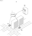
- FIG. 1 is a diagram illustrating an example of an autonomous driving system 10 according to an embodiment of the present disclosure.
- the autonomous driving system 10 includes a map generating car 100, a server 200, and a map using car 300.
- the map generating car 100 may collect information for generating a map and transmit the information to the server 200.
- the map generating car 100 may transmit, to the server 200, point cloud information on the ground, which is acquired using a multichannel light detection and ranging (LiDAR) sensor during driving on a target place for generating a map.
- LiDAR multichannel light detection and ranging
- a LiDAR sensor refers to a sensor system that emits a high output pulse laser with a specific frequency and measures time taken to receive a reflected wave from an object to acquire information on a distance to the object.
- a LiDAR sensor may be a LiDAR sensor that is capable of performing image modeling of a space as well as distance information in a traveling direction of a laser beam. That is, the LiDAR sensor may be a LiDAR sensor that is capable of collecting point cloud information of a ground via point-scanning.
- the LiDAR sensor is a multichannel LiDAR sensor that uses a plurality of lasers with different frequencies for respective channels, but not usually a general LiDAR sensor that uses a laser with a single frequency.
- the map generating car 100 may scan the road using a laser with a plurality of frequencies while driving on the road of the corresponding area, acquire point cloud information for each frequency channel for the road, and transmit the information to the server 200, via a network 1.
- the server 200 may generate a multichannel map of the corresponding road using the point cloud information for each channel for the road, received from the map generating car 100.
- the server 200 may apply various map generating algorithms to the point cloud information for each channel to generate the multichannel map with a plurality of channels and store the generated multichannel map.
- the generated multichannel map may be a detailed map containing reflectivity information on each point of a road surface and may be used for autonomous driving.
- map generated for autonomous driving is technologically capable of being displayed to a consumer, it would be obvious to one of ordinary skill in the art that the map is used to accurately recognize a vehicle position and is not viewed by the consumer.
- the map using car 300 may determine a current position based on the multichannel map.
- the map using car 300 may request the server 200 for map data containing the current position and receive corresponding multichannel map data from the server 200.
- the map using car 300 may acquire point cloud information for each channel of a surrounding ground at the current position of the car 300 using the multichannel LiDAR sensor.
- the map using car 300 may acquire point cloud information for each channel of a ground while rotating by 360 degrees the multichannel LiDAR sensor that installed on the map using car 300 towards the ground, without being limited thereto.
- the map using car 300 may match the multichannel map data received from the server 200 and the point cloud information on the ground, acquired through the multichannel LiDAR sensor and determine a current position of the map using car 300 on the multichannel map.
- a map may be generated using the multichannel LiDAR sensor so as to generate a detailed map containing a texture of materials (e.g., a lane or a packaging material) constituting the ground (e.g., a road surface) and an accurate position of a vehicle may be determined on the generated detailed map so as to more accurately determine a position of the vehicle. Accordingly, autonomous driving of a vehicle may become easier.
- a texture of materials e.g., a lane or a packaging material
- the ground e.g., a road surface
- a map i.e., a detailed map by the server 200
- generation of a map i.e., a detailed map by the server 200 will be described with reference to FIGS. 2, 3A , 3B, 4A , 4B, 4C , 5A , 5B , 6A, 6B , 7A , and 7B .
- FIG. 2 is a diagram illustrating an example of a map generating environment according to an unclaimed aspect of the present disclosure.
- the map generating car 100 may collect information for generating a map, i.e., a detailed map.
- the map generating car 100 may acquire the point cloud information for each channel of a surrounding road (a paved road in the example of FIG. 2 ) of the map generating car 100 using the installed multichannel LiDAR sensor and transmit the point cloud information to the server 200.
- the map generating car 100 may be connected to the server 200 through a network 1 such as the Internet.
- the server 200 may receive the point cloud information, generate a map, and store the generated map.
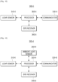
- the server 200 may include a communicator 210, a processor 220, and a storage 230.
- the communicator 210 may be connected to the network 1 and may communicate with an external vehicle via various wired and wireless communication methods.
- the communicator 210 may communicate with an external vehicle using a distant communication module or a local area communication module.
- the communicator 210 may communicate with a vehicle according to communication standard such as Institute of Electrical and Electronics Engineers (IEEE), 3rd generation (3G), 3G partnership project (3GPP), long term evolution (LTE), and global positioning system (GPS).
- the communicator 210 may communicate with a vehicle according to communication standard such as Wi-Fi, Bluetooth, near field communication (NFC), ZigBee, and Picocast.
- the communicator 210 may receive the point cloud information for each channel for the ground, which is acquired and transmitted by the map generating car 100.
- the processor 220 may control an overall operation of the server 200.
- the processor 220 may apply various map generating algorithms to the point cloud information for each channel, received through the communicator 210, to generate a multichannel map and store the generated multichannel map in the storage 230.
- the processor 220 may synthesize the received point cloud information for each channel into single-channel point cloud information and apply a map generating algorithm to the synthesized single-channel point cloud information to generate a single-channel.
- the processor 220 may remove influence of ambient light from the point cloud information for each channel, acquired by the map generating car 100, and generate the aforementioned multichannel map or single-channel map.
- the generated map data may be stored in the storage 230. As described later, the map data may be transmitted to the map using car 300 according to transmission request of the map data of the map using car 300.
- a method of selecting a frequency used for each channel of a multichannel LiDAR sensor will be described with reference to FIGS. 3A and 3B .
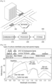
- FIGS. 3A and 3B are diagrams illustrating an example of a reflectivity of each material type according to a wavelength of an electromagnetic wave according to unclaimed aspects of the present disclosure.
- FIG. 3A shows reflectivity according to a wavelength of an electromagnetic wave for each type of a surface such as vegetation, dry soil, wet soil, clear lake water, and turbid river water.
- FIG. 3B shows reflectivity according to a wavelength of an electromagnetic wave for each type of a mineral such as calcite, kaolinite, hematite, and montmorillonite.
- reflectivity of an electromagnetic wave may be varied according to a type of a surface or mineral.
- the materials When materials have the same reflectivity in a specific wavelength, the materials are not capable of being distinguished through a laser with a frequency of the wavelength. That is, as a reflectivity difference between materials in a predetermined wavelength is larger, the materials may be easily distinguished via laser with the frequency of the wavelength.
- a frequency with a large reflectivity difference between the materials constituting the ground may be selected.
- a wavelength of FIG. 3A may be classified into three regions (0.4 to 1.0 micrometer periods, 1.0 to 1.6 micrometer periods, and 1.6 to 2.2 micrometer periods), variance of reflectivity values of surface types for respective wavelengths of an electromagnetic wave may be calculated for each of the three regions, and then wavelengths with a highest variance value may be selected. Reciprocals of the three selected wavelengths may be frequencies of a laser of each channel of the 3-channel LiDAR sensor.
- a wavelength of FIG. 3B may be classified into four regions, standard deviation of reflectivity values of minerals for respective wavelengths may be calculated for each of the four regions, and then wavelengths with a highest standard deviation value may be selected so as to configure each channel layer frequency of the 4-channel LiDAR sensor.
- an example of selecting a multichannel frequency is not limited thereto.
- the number of channels may be two or five or more.
- reflectivity data according to a frequency (or a wavelength) of materials is not necessarily divided into the number of channels, and thus, for example, a reflectivity difference (e.g., variance) between materials may be calculated for all frequencies, and then frequencies may be selected by as much as the number of channels in an order from a highest difference.
- a laser of the selected frequency may be used in a multichannel LiDAR sensor so as to clearly distinguish materials constituting the ground, and accordingly, it may be possible to generate a more detailed map and to accurately determine a position of a vehicle on the map.
- FIGS. 4A , 4B, and 4C are diagrams illustrating an example of a procedure of generating a map by servers 200-1 and 200-2 according to unclaimed aspects of the present disclosure.
- FIG. 4A is a diagram illustrating an example of generation of a multichannel map.
- a map generating car 100-1 may include a LiDAR sensor 110-1 and a communicator 120-1.
- Basic components of a car, constituting the map generating car 100-1, for example, a steering device, an acceleration device, a deceleration device, a door, and an electronic control unit (ECU) are not related to the essence of the disclosure and, thus, will not be illustrated or described.
- the LiDAR sensor 110-1 may acquire point cloud information on a surrounding ground of the map generating car 100-1 using a multichannel laser.
- the point cloud information may include poser information and reflectivity information of each sampling point of the ground.
- the LiDAR sensor 110-1 may include a laser transmitter (not shown) and a laser receiver (not shown) for each channel.
- the LiDAR sensor 110-1 may be installed at an appropriate position for scanning of the surrounding ground of the vehicle, for example, at an upper end portion of the map generating car 100-1 so as to emit a laser beam toward the ground, without being limited thereto.
- the communicator 120-1 may communicate with an external device.
- the communicator 120-1 may communicate with the external device (e.g., a cloud server) 200-1 positioned outside the map generating car 100-1 using a distant communication module or a local area communication module.
- the communicator 120-1 may communicate with the server 200-1 according to communication standard such as IEEE, 3G, 3GPP, LTE, and GPS.
- the communicator 120-1 may communicate with the server 200-1 according to communication standard such as Wi-Fi, Bluetooth, NFC, ZigBee, and Picocast.
- the communicator 120-1 may transmit the point cloud information for each channel, acquired through the LiDAR sensor 110-1, to the server 200-1.
- the server 200-1 may generate a multichannel map using the received information and the multichannel map in a storage 230-1.
- a processor 220-1 may apply a simultaneous localization and mapping (SLAM) algorithm to the point cloud information for each channel, received through the communicator 210-1.
- the point cloud information for each channel which is acquired with respect to the ground by the map generating car 100-1 through the SLAM 221-1 algorithm, may be optimized so as to estimate pose information.
- the pose information may include x and y coordinates and direction information on a map to be generated.
- the processor 220-1 may back-project sensor information for each pose and perform grid mapping 222-1. As the result of the grid mapping 222-1, a multichannel map 223-1 may be generated.
- the generated multichannel map 223-1 may be a multichannel 2D reflectivity map containing channels corresponding to respective channels of the multichannel LiDAR sensor 110-1 installed in the map generating car 100-1.
- the multichannel map 223-1 may include pixel-unit reflectivity information for each channel and may be a detailed map containing a lane position or texture information of a road on which the map generating car 100-1 drives.
- the processor 220-1 may store the aforementioned generated multichannel map 223-1 in the storage 230-1.
- the reflectivity of a road surface may be changed according to time and, thus, the processor 220-1 may store a mean value or variance of reflectivity in the multichannel map.
- the map generating car 100-1 may drive on the same road a plurality of numbers of times and transmit point cloud information for each of a plurality of channels with respect to the same point to the server 200-1, and the server 200-1 may store a mean or variance value together for each channel in the multichannel map.
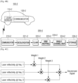
- FIG. 4B illustrates a procedure of generating a single-channel map by the server 200-2 according to an unclaimed aspect of the present disclosure.
- a map generating car 100-2 of FIG. 4B is generally the same as the map generating car 100-1 of FIG. 4A .
- the server 200-2 may generate a single-channel map using the received information and store the single-channel map in a storage 230-2.
- a processor 220-2 may synthesize the point cloud information for each channel into one channel.
- decolorization 221-2 may refer to such processing by the processor 220-2, that is, an operation of synthesizing multichannel point cloud information into single-channel point cloud information.
- the processor 220-2 may multiply each channel constituting a multichannel by a fixed weight to synthesize one channel. For example, in the case of point cloud information received through a 4-channel LiDAR sensor, point cloud information items for respective channels may be multiplied by a weight of 25% and summed to synthesize single-channel point cloud information.
- the processor 220-2 may multiply information acquired through respective channels by fixed weights, and for example, multiply information acquired through a first channel by 20%, multiply information acquired through a second channel by 30%, and multiply information acquired through a third channel by 50%, and sum the results to synthesize single-channel point cloud information.
- a channel with a large reflectivity difference between materials may be multiplied by a high weight. That is, in the above example, a reflectivity difference between materials in a frequency of a third channel may be largest and a reflectivity difference between materials in a frequency of a first channel may be smallest. That is, for example, the processor 220-2 may calculate variance or standard deviation for each channel of the point cloud information for each channel and multiply a channel with a greater calculated variance value or standard deviation by a greater weight.
- the processor 220-2 may adaptively change a weight for each scan of a multichannel LiDAR sensor 110-2 and multiply each channel by a weight to synthesize single-channel point cloud information.
- the scan may be information acquired during one operation of the LiDAR sensor 110-2, and for example, may be point cloud information acquired during one rotation, i.e., 360°of the LiDAR sensor 110-2, or 1/3 rotation, i.e., 120°, without being limited thereto.
- the processor 220-2 may calculate variance values of channel information items for respective scans, normalize the channel information items by as much as the variance values, and then sum the normalized channel information items to synthesize single-channel point cloud information.
- the processor 220-2 may calculate variance or standard deviation values of reflectivity information contained in point cloud information for each channel for respective scans and multiply a channel with a greater calculated variance or standard deviation value by a higher weight to synthesize single-channel point cloud information.
- FIG. 4C is a diagram illustrating a concept of an example in which the processor 220-2 performs the decolorization 221-2 as described above when 3-channel point cloud information is received through the communicator 210-2.
- Weights 1 to 3 to be multiplied to each channel information item may be fixed or may be adaptively changed for each scan, as described above.
- the processor 220-2 may apply an SLAM 222-2 algorithm to single-channel point cloud information and perform grid mapping 223-2 to generate a map, and in this case, the generated map may be a single-channel map 224-2.
- the processor 220-2 may store the generated single-channel map 224-2 in the storage 230-2.
- a processor (not shown) included in the map generating car 100-2 may perform decolorization on the point cloud information for each channel, acquired through the multichannel LiDAR sensor 110-2, as described above. Accordingly, when the point cloud information for each channel is synthesized into single-channel point cloud information, the map generating car 100-2 may transmit the synthesized single-channel point cloud information to the server 200-2 through a communicator 120-2.
- the server 200-2 may receive single-channel point cloud information from the map generating car 100-2 through the communicator 210-2, apply the SLAM 222-2 algorithm to the received single-channel point cloud information, and perform the grid mapping 223-2 to generate the single-channel map 224-2.
- the processor 220-2 of the server 200-2 may not necessarily perform the decolorization 221-2 separately.
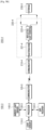
- FIGS. 5A and 5B are diagrams illustrating an example of a procedure in which servers 200-3 and 200-4 remove reflected light from multichannel point cloud information and generates a map according to unclaimed aspects of the present disclosure.
- the reflected light may be obtained by reflecting light of a light source, for example, the sun or a streetlamp and may distort LiDAR sensor information, thereby degrading accuracy of map generation or position recognition. That is, since a LiDAR sensor 110 of the map generating car 100 may scan a surrounding ground of the car 100 to acquire multichannel point cloud information, in this case, reflected light reflected by the surrounding ground may distort information acquired through the LiDAR sensor 110. Accordingly, it may be necessary to remove influence of the reflected light from information acquired through the LiDAR sensor 110.
- a processor 220-3 of the server 200-3 may perform rasterization 221-3 on the received multichannel point cloud information to acquire 2D data. Since the point cloud information acquired through the LiDAR sensor is three-dimensional (3D) information, it may be necessary to convert 3D information into 2D information in order to remove reflected light. Accordingly, the processor 220-3 may rasterize 3D information for each channel to 2D information for each channel.
- 3D three-dimensional
- the processor 220-3 may perform reflected-light removal 222-3 from the rasterized 2D data for each channel.
- the processor 220-3 may apply various algorithms for removing reflected light to the 2D data.
- the processor 220-3 may apply at least one of analyzing methods including color space analysis for specularity removal, image-plane spatial analysis, and video sequence analysis to the rasterized 2D data to perform reflected-light removal.
- the processor 220-3 may apply an SLAM 223-3 algorithm to the 2D data for each channel, from which the reflected light is removed and perform grid mapping 224-3 to generate a multichannel map 225-3 from which influence of the reflected light is removed, as described with reference to FIGS. 4A to 4C .
- Decolorization 226-3 may be performed on the 2D data for each channel, from which reflected light is removed, to synthesize a single-channel, an SLAM 227-3 algorithm may be applied to the single-channel, and grid mapping 228-3 may be performed to generate a single-channel map 229-3 from which influence of reflected light is removed.
- a processor included in a map generating car may perform decolorization on the point cloud information for each channel and transmit the point cloud information for each channel to the server 200-3
- the processor 220-3 of the server 200-3 may perform the rasterization 221-3 on the single-channel point cloud information received through the communicator 210-3 to perform the reflected-light removal 222-3 and then generate the single-channel map 229-3 through the SLAM 227-3 and the grid mapping 228-3 without needing to re-perform the decolorization 226-3.
- the generated multichannel map 225-3 or the single-channel map 229-3 may be stored in a storage 230-3.
- FIG. 5B illustrates an example of generation of a map from which influence of reflected light is removed according to an unclaimed aspect of the present disclosure.
- a map generating car 100-3 may include a LiDAR sensor 110-3, a communicator 120-3, the processor 130-3, an ambient light sensor 140-3, a GPS receiver 150-3, and an inertial sensor (not shown).
- the LiDAR sensor 110-3 may transmit a plurality of laser beams with a plurality of frequencies toward a surrounding ground of the map generating car 100-3 during driving of a vehicle (the map generating car 100-3) to acquire multichannel point cloud information on the surrounding ground.
- the ambient light sensor 140-3 may detect ambient light of the vehicle.
- the ambient light sensor 140-3 may detect intensity of sunlight that shines the map generating car 100-3.
- the ambient light sensor 140-3 may include various illuminance sensors without being limited thereto.
- a position of the vehicle, in which the ambient light sensor 140-3 is installed may not also be limited to a specific position and, thus, the ambient light sensor 140-3 may be installed at a position so as to experimentally and easily detect intensity of ambient light.
- the GPS receiver 150-3 may receive a GPS signal and calculate positional information of the vehicle.
- the GPS receiver 150-3 may receive the GPS signal transmitted from a preset number (e.g., three or more) of satellites and calculate current positional information of the vehicle.
- the processor 130-3 may calculate a current position of the vehicle based on the received GPS signal.
- the inertial sensor (not shown) may determine a progress direction of a vehicle during movement of the vehicle.
- the processor 130-3 may determine a position of the sun based on a position of the vehicle.
- the processor 130-3 may recognize a current position of the sun on the earth based on information on the current weather and time.
- the processor 130-3 may recognize the current position of the vehicle on the earth through the GPS receiver 150-3 and recognize the progress direction of the vehicle through the inertial sensor (not shown) and, thus, may determine the position of the sun based on the position of the vehicle.
- the processor 130-3 may determine a current position of the sun, that is, which side the sun is positioned among left, right, front, rear, and central directions of the map generating car 100-3 and generate information on the determined position of the sun.
- the processor 130-3 may control the communicator 120-3 to transmit, to the server 200-4, the point cloud information for each channel, acquired through the multichannel LiDAR sensor 110-3, the ambient light information (e.g., information on intensity of sunlight) detected through the ambient light sensor 140-3, and the aforementioned generated information on the position of the sun based on the current position of the vehicle.
- the ambient light information e.g., information on intensity of sunlight
- the server 200-4 may generate a multichannel map or single-channel map from which reflected light is removed using the received information and store the same in the storage 230-3.
- a processor 220-4 may perform rasterization 221-4 on the received multichannel point cloud information in order to remove reflected light from the point cloud information for each channel. Then, the processor 220-4 may apply various algorithms for removing reflected light to the rasterized 2D data for each channel to perform reflected-light removal 222-4.
- the processor 220-4 may perform the reflected-light removal 222-4 using at least one of ambient light information and information on a position of the sun, received from the map generating car 100-3.
- the processor 220-4 may increase intensity of the reflected-light removal 222-4, and when the intensity of the ambient light is low, the processor 220-4 may reduce the intensity of the reflected-light removal 222-4.
- the reflected-light removal 222-4 is performed using ambient light is not limited thereto, and for example, when intensity of sunlight is preset intensity or more, the reflected-light removal 222-4 may be performed, and when the intensity of sunlight is less than present intensity, the reflected-light removal 222-4 may not be performed.
- the processor 220-4 may increase the intensity of the reflected-light removal 222-4 in a region corresponding to a front left side of the map generating car 100-3 in the rasterized 2D data for each channel. In this manner, the processor 220-4 may apply information on a position of the sun and perform the reflected-light removal 222-4.
- the processor 220-3 may perform the SLAMs 222-3 and 227-3 and the grid mapping 225-3 and 228-3 to generate the multichannel map 225-3 or the single-channel map 229-3, as described with reference to FIG. 5A .
- the decolorization 226-3 may be performed by the processor 220-4 of the server 200-4 or the processor 130-3 of the map generating car 100-3.
- FIGS. 6A and 6B are flowcharts of a method of generating a map according to unclaimed aspects of the present disclosure.
- FIG. 6A is a flowchart of a method of generating a multichannel map according to an unclaimed aspect of the present disclosure.
- the map generating car 100 may acquire the point cloud information for each channel on the ground through a multichannel LiDAR sensor while driving on a place as a target for generating a multichannel map in operation S610-1.
- the server 200 may generate a multichannel map using the received point cloud information for each channel in operation S610-2.
- the server 200 may apply various simultaneous localization and mapping (SLAM) algorithms to the point cloud information for each channel and perform grid mapping to generate a multichannel map of the ground of a corresponding place.
- SLAM simultaneous localization and mapping
- the generated multichannel map may be stored in the storage 230 of the server 200 and, then, may be transmitted to the map using car 300 according to a request of the map using car 300.
- FIG. 6B is a flowchart of a method of generating a single-channel map according to an unclaimed aspect of the present disclosure.
- the map generating car 100 may acquire the point cloud information for each channel on the ground through a multichannel LiDAR sensor while driving on a place as a target for generating a single-channel map in operation S610-2. Accordingly, the map generating car 100 may transmit the acquired point cloud information for each channel to the server 200 (illustrated in FIG. 1 ).
- the server 200 may perform decolorization of multiplying the received point cloud information for each channel by a weight for each channel to synthesize point cloud information of one channel in operation S620-2.
- the server 200 may apply a SLAM algorithm to the single-channel point cloud information synthesized through decolorization and perform grid mapping to generate a single-channel map of the ground of a corresponding place in operation S630-2.
- Decolorization may be performed by the map generating car 100.
- the map generating car 100 may multiply the multichannel point cloud information acquired through the multichannel LiDAR sensor by a weight for each channel to synthesize single-channel point cloud information and transmit the synthesized single-channel point cloud information to the server 200.
- the server 200 may apply a SLAM algorithm directly to the single-channel point cloud information received from the map generating car 100 and perform grid mapping to generate a single-channel map without needing to perform separate decolorization in operation S620-2.
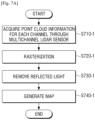
- FIGS. 7A and 7B are flowcharts of a method of removing or reducing distortions, such as reflected light from information acquired through a LiDAR sensor and generating a map according to unclaimed aspects of the present disclosure.
- the map generating car 100 may acquire point cloud information for each channel on the ground through the multichannel LiDAR sensor while driving to a place as a target for generating a map in operation S710-1.
- the acquired multichannel point cloud information may be transmitted to the server 200 (illustrated in FIG. 1 ) without changes or may be synthesized into single-channel point cloud information via the aforementioned decolorization and transmitted to the server 200.
- the server 200 may perform rasterization on the received multichannel point cloud information or single-channel point cloud information to generate 2D data in operation S720-1.
- the server 200 may apply various algorithms for removing or minimizing the reflected light to the rasterized multichannel or single-channel 2D data to perform reflected-light removal or reduction in operation S730-1.
- the server 200 may apply an SLAM algorithm to 2D data on which reflected-light removal or reduction is performed and perform grid mapping to generate a multichannel map or a single-channel map of the ground of a corresponding place (S740-1).
- FIG. 7B is a flowchart of a method for generating a map from which reflected light is removed according to an unclaimed aspect of the present disclosure.
- the map generating car 100 may acquire point cloud information for each channel on the ground through a multichannel LiDAR sensor while driving on a place as a target for generating a map in operation S710-2.
- the map generating car 100 may detect intensity of ambient light through an ambient light sensor in operation S720-2.
- the ambient light may be sunlight without being limited thereto.
- the map generating car 100 may calculate positional information of the sun in operation S730-2.
- the map generating car 100 may determine a position of the sun based on a position of the map generating car 100 using information on current weather and time, information on a current position of the map generating car 100 through a GPS receiver, and information on a moving direction of the map generating car 100 through an inertial sensor.
- the map generating car 100 may transmit, to the server 200 (illustrated in FIG. 1 ), the multichannel point cloud information on the ground, ambient light information, and information on a position of the sun based on the position of the map generating car 100.
- the server 200 may perform rasterization to the multichannel point cloud information received from the map generating car 100 to generate 2D data in operation S740-2 and apply various algorithms for removing reflected light to the rasterized 2D data in operation S750-2.
- the server 200 may adjust intensity of ambient-light removal or reduction by using ambient light information, for example, information on intensity of sunlight.
- the server 200 may apply information on a position of the sun when an algorithm for removing or reducing ambient light is applied and perform reflected-light removal.
- the server 200 may apply an SLAM algorithm to 2D data from which reflected light is removed and perform grid mapping to generate a map of the ground of a corresponding place in operation 760-2.
- the map may be generated as a multichannel map or a single-channel map according to decolorization is further performed in each operation, as described above.
- the server 200 may directly generate a map using the point cloud information for each channel, acquired through a LiDAR sensor, transmit the generated map to the server 200, and store the same in the server 200.
- the map generated through the server 200 or the map generating car 100 may be a detailed map containing reflectivity information on each point of the ground (e.g., a road surface), may have a slight error of a unit of centimeter compared with an actual ground, and may be used to accurately recognize a position of the map using car 300, which will be described later. Accordingly, autonomous driving may be more easily performed.
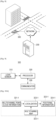
- FIG. 8 is a diagram illustrating an example of a position recognition environment of a vehicle according to an embodiment of the present disclosure.
- the map using car 300 recognizes an accurate position of the map using car 300 in a map based on the map.
- the map using car 300 is connected to the server 200 through various networks 1 such as the Internet and receives map data containing a place on which the map using car 300 currently drives from the server 200.
- the map data received from the server 200 may refer to map data of the map generated by the server 200 or the map generating car 100, as described above with reference to FIGS. 2, 3A , 3B, 4A , 4B, 4C , 5A , 5B , 6A, 6B , 7A , and 7B .
- the map using car 300 acquires point cloud information for each channel on a surrounding ground (a paved road in the example of FIG. 8 ) of the car 300 using a multichannel LiDAR sensor installed in the map using car 300.
- the map using car 300 maps the map data received from the server 200 and acquired through the LiDAR sensor to determine a current position of the map using car 300 in the map.
- the map using car 300 may be any vehicle that recognizes a position based on the map received through the external server 200 and uses the recognized position as information for autonomous driving.
- FIG. 9 is a block diagram illustrating a configuration of the map using car 300 according to an embodiment of the present disclosure.
- the map using car 300 includes a LiDAR sensor 310, a processor 320, and a communicator 330.
- General basic car components constituting the map using car 300 for example, a steering device, an acceleration device, a deceleration device, a door, and an ECU are not necessarily related to the essence of the embodiments of the disclosure and, thus, such components will not be further illustrated or described.
- the LiDAR sensor 310 is the same as the LiDAR sensors 110-1, 110-2, and 110-3 which have been described with reference to FIGS. 2, 3A , 3B, 4A , 4B, 4C , 5A , 5B , 6A, 6B , 7A , and 7B and, thus, a repeated description thereof will not be provided.
- a frequency for each channel of the LiDAR sensor 310 used in the map using car 300 may be the same as a frequency for each channel of a LiDAR sensor installed in the map generating car 100 used to generate map data received through the communicator 330, as described below.
- the map generating car 100 may include a 3-channel LiDAR sensor including a first channel using a laser of a first frequency, a second channel using a laser of a second frequency, and a third channel using a laser of a third frequency and acquire 3-channel point cloud information using the 3-channel LiDAR sensor.
- the LiDAR sensor 310 that needs to be included in the map using car 300 in order to recognize a position based on the received map may be a 3-channel LiDAR sensor including a first channel using a laser of a first frequency, a second channel using a laser of a second frequency, and a third frequency using a laser of a third frequency, such as a LiDAR sensor of the map generating car 100.
- the LiDAR sensor 310 acquires point cloud information for each channel on a surrounding ground of the map using car 300 using a multichannel laser.
- the communicator 330 communicates with an external server to transmit and receive various information items.
- the communicator 330 may request the external server 200 to transmit map data and receive the map transmitted in response to the request of the external server 200 under control of the processor 320.
- the communicator 330 may be connected to the network 1 via various wired and wireless communication methods and may communicate with the server 200.
- the communicator 330 may communicate with the external server 200 using a distant communication module or a local area communication module.
- the communicator 330 may communicate with the external server 200 according to communication standard such as IEEE, 3G, 3GPP, LTE, and GPS.
- the communicator 330 may communicate with a vehicle according to communication standard such as Wi-Fi, Bluetooth, NFC, ZigBee, and Picocast.
- the processor 320 controls an overall operation of the map using car 300.
- the processor 320 controls the communicator 330 to receive map data from the external server 200.
- the processor 320 controls the LiDAR sensor 310 to acquire multichannel point cloud information on a ground (e.g., a road surface) on which the map using car 300 drives. Accordingly, the processor 320 determines a position of the map using car 300 in the map received from the external server 200 based on the point cloud information for each channel, acquired through the LiDAR sensor 310.
- FIGS. 10A , 10B , 11A , 11B , 12, 13 , 14A , and 14B will be described in detail with reference to FIGS. 10A , 10B , 11A , 11B , 12, 13 , 14A , and 14B .
- FIG. 10A illustrates an example in which the map using car 300 determines a position based on a multichannel map according to an unclaimed aspect of the present disclosure.
- a processor 320-1 of the map using car 300 may match multichannel map data 322-1 received from the server 200 (illustrated in FIG. 8 ) through the communicator 330 (illustrated in FIG. 9 ) and the multichannel point cloud information 321-1 acquired through the LiDAR sensor 310 to determine in operation 323-1 a localized position of the map using car 300 in the multichannel map.
- the multichannel map may be reflectivity information corresponding to the number of channels for each point on a map. That is, for example, in the case of a 3-channel map, a specific point on the map may include three reflectivity information items.
- the LiDAR sensor 310 also acquires point cloud information for each channel for every scan point and, thus, for example, in the case of a three-channel LiDAR sensor, three-point cloud information items may be acquired for every scan point.
- the processor 320-1 may map the multichannel point cloud information acquired through the LiDAR sensor 310 and the multichannel map to determine a current position of the map using car 300 in the multichannel map.
- a plurality of channel information items is jointed and compared with each other and thus, a position in a map may be more accurately specified.
- the processor 320-1 may generate current positional information 324-1 of the map using car 300 in multichannel map data.
- the positional information 324-1 may include x and y coordinates and direction information of the map using car 300 in the multichannel map without being limited thereto.
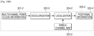
- FIG. 10B illustrates an example in which the map using car 300 (illustrated in FIG. 8 ) determines a position based on a single-channel map according to an embodiment of the present disclosure.
- a processor 320-2 of the map using car 300 determines in operation 324-2 a localized position of the map using car 300 (illustrated in FIG. 8 ) in the single-channel map data 323-2 using the single-channel map data 323-2 received from the server 200 through the communicator 330 and multichannel point cloud information 321-2 acquired through the LiDAR sensor 310.
- the processor 320-2 multiplies multichannel point cloud information acquired through the LiDAR sensor 310 with a weight for each channel to synthesize single-channel point cloud information. This procedure is referred to as decolorization 322-2.
- the decolorization 322-2 is the same as in the description of generation of a single-channel map with reference to FIG. 4B and, thus, a repeated description thereof will not be provided.
- a weight that is multiplied to each channel of the multichannel point cloud information acquired through the LiDAR sensor 310 by the processor 320-2 of the map using car 300 may be the same as a weight applied in a generating procedure of the single-channel map 323-2, without being limited thereto.
- the server 200 may also transmit information on a weight applied to a map generating procedure during transmission of the single-channel map 323-2.
- the processor 320-2 matches a single-channel map 323-3 and single-channel point cloud information to determine in operation 324-2 a position of the map using car 300 and generate positional information 325-2.
- FIG. 11A illustrates an operation of the processor 320 that determines a position of the map using car 300 when the map using car 300 (illustrated in FIG. 8 ) receives a generated map from which reflected light is removed like in the example of FIG. 5A according to an unclaimed aspect of the present disclosure.
- FIG. 11B illustrates an operation of the processor 320 that determines a position of the map using car 300 when the map using car 300 (illustrated in FIG. 8 ) receives a generated map from which reflected light is removed like in the example of FIG. 5A according to an embodiment of the present disclosure.
- FIG. 11A illustrates a case in which the map using car 300 receives a multichannel map 324-3 from which reflected light is removed.
- a processor 320-3 may convert multichannel point cloud information 321-3 acquired through the LiDAR sensor 310 into 2D information using rasterization 322-3. Then, the processor 320-3 may apply in operation 323-3 the various algorithms for removing reflected-light described with reference to FIG. 5A to the rasterized 2D information to generate multichannel 2D information from which reflected light is removed and matched to the multichannel 2D information and the multichannel map 324-3 from which reflected light is removed to determine in operation 325-3 a localized position of the map using car 300 in the multichannel map 324-3. Thus, the processor 320-3 may generate positional information 326-3 of the map using car 300.
- FIG. 11B illustrates a case in which the map using car 300 (illustrated in FIG. 8 ) receives a single-channel map 325-4 from which reflected light is removed.
- a processor 320-4 performs decolorization 322-4 on multichannel point cloud information 321-4 acquired through the LiDAR sensor 310 to synthesize single-channel point cloud information. Then, the processor 320-4 converts the synthesized single-channel point cloud information into 2D information using rasterization 323-4 and apply in operation 324-4 the various algorithms for removing reflected light described with reference to FIG. 5A to the rasterized 2D information to generate 2D information from which reflected light is removed.
- the processor 320-4 matches the single-channel map 325-4 from which reflected light is removed and the rasterized 2D information from which reflected light is removed to determine in operation 326-4 a localized position of the map using car 300 in the single-channel map 325-4. Accordingly, the processor 320-4 generates positional information 327-4 of the map using car 300.
- the generated positional information 324-1, 325-2, 326-3, and 327-4 may be used as information for autonomous driving.
- FIG. 12 is a block diagram illustrating components of a vehicle according to an embodiment of the present disclosure.
- a map using car 300-5 includes a LiDAR sensor 310-5, a processor 320-5, a communicator 330-5, and optionally a GPS receiver 340-5.
- a map using car 300-5 includes a LiDAR sensor 310-5, a processor 320-5, a communicator 330-5, and optionally a GPS receiver 340-5.
- the same components of FIG. 12 as those of the map using car 300 illustrated in FIG. 9 will not be repeatedly described and thus, a repeated description will not be provided.
- the GPS receiver 340-5 may receive a GPS signal and determine a position of the map using car 300-5.
- the GPS receiver 340-5 may receive a GPS signal from a preset number of external GPS satellites and calculate a position of the map using car 300-5 based on the received GPS signal.
- the processor 320-5 may calculate the position of the map using car 300-5 based on the received GPS signal, needless to say.
- the processor 320-5 may primarily determine the position of the map using car 300 in the map data received from the server 200 based on the GPS signal received through the GPS receiver 340-5. Then, the processor 320-5 may secondarily determine the position of the map using car 300-5 using the multichannel point cloud information acquired through the LiDAR sensor 310-5, as described above.
- a computational load of the processor 320-5 may be reduced compared with in the case in which a position of the map using car 300-5 is determined using only information acquired through the LiDAR sensor 310-5. That is, the position calculated through the GPS signal has a relatively high error range and, thus, the position of the map using car 300-5 may be primarily determined through the GPS signal, and map data within a preset range (e.g., a general error range for determining a position through the GPS signal) from the position determined through the GPS signal and information acquired through the LiDAR sensor 310-5 to accurately determine the position of the map using car 300-5, thereby reducing a computational load of the processor 320-5 compared with a case in which entire map data received from the server 200 is matched.
- a preset range e.g., a general error range for determining a position through the GPS signal
- the processor 320-5 may request the server 200 (illustrated in FIG. 8 ) to transmit map data of a region corresponding to a preset range from the position of the map using car 300-5, which is determined using the GPS signal. That is, the processor 320-5 may not request the server 200 to transmit map data of all regions that are stored in the server 200 but may request the server 200 to transmit only map data of a region corresponding to a predetermined range from the position determined through the GPS signal while the map using car 300-5 drives, thereby reducing a computational load of the processor 320-5.
- FIG. 13 is a block diagram illustrating components of a map using car 300-6 according to an embodiment of the present disclosure.
- the map using car 300-6 includes a LiDAR sensor 310-6, a processor 320-6, a single-channel map 327-8 (illustrated in FIG. 14B ), a communicator 330-6, optionally a GPS receiver 340-6, and optionally an ambient light sensor 350-6.
- a description of FIG. 12 a repeated description of the same components as the map using cars 300 and 300-5 illustrated in FIGS. 9 and 12 will be omitted here.
- the ambient light sensor 350-6 may detect ambient light of the map using car 300-6 and provide the detected ambient light information to the processor 320-6.
- the ambient light sensor 350-6 may detect intensity of sunlight that shines the map using car 300-6 and provide the intensity information of sunlight to the processor 320-6.
- the ambient light sensor 350-6 may include various illuminance sensors without being limited thereto.
- the processor 320-6 may determine a position of the map using car 300-6 through a GPS signal received through the GPS receiver 340-6 and determine a position of the sun based on a current time.
- a moving direction of the map using car 300-6 may also be determined through an inertial sensor. Accordingly, the processor 320-6 may determine a position of the sun based on the position of the map using car 300-6.
- the processor 320-6 may determine a current position of the sun, that is, which side the sun is positioned among left, right, front, rear, and central directions of the map using car 300-6 and generate information on the determined position of the sun.
- FIG. 14A is a diagram illustrating an example of a procedure in which the map using car 300-6 of FIG. 13 determines a position in a multichannel map 326-7 according to an unclaimed aspect of the present disclosure.
- the processor 320-6 may perform rasterization 322-7 on multichannel point cloud information 321-7 and apply various algorithms for removing reflected light to the rasterized 2D data for each channel rasterization 322-7 to perform reflected-light removal 325-7.
- the processor 320-6 may perform the reflected-light removal 325-7 using at least one of ambient light information 323-7 acquired through the ambient light sensor 350-6 and determine positional information 324-7 of the sun.
- the processor 320-6 may increase intensity of the reflected-light removal 325-7, and when intensity of ambient light is low, the processor 320-6 may reduce intensity of the reflected-light removal 325-7.
- the present disclosure is not limited to an example in which the reflected-light removal 325-7 is performed using ambient light information. For example, when intensity of sunlight is equal to or more than preset intensity, the reflected-light removal 325-7 may be performed, and the intensity of sunlight is less than preset intensity, the reflected-light removal 325-7 may not be performed.
- the processor 320-6 may increase the intensity of the reflected-light removal 325-7 in a region corresponding to a front left side of the map using car 300-6 in the rasterized 2D data for each channel. In this manner, the processor 320-6 may apply information on a position of the sun and perform the reflected-light removal 325-7.
- the processor 320-6 may match the multichannel map 326-7 received through the server 200 through the communicator 330-6 and the rasterized multichannel 2D information from which reflected light is removed to determine in operation 327-7 a position of the map using car 300-6 in the multichannel map 326-7 and generate positional information 328-7.
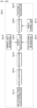
- FIG. 14B is a diagram illustrating an example of a procedure in which the map using car 300-6 of FIG. 13 determines a position in a single-channel map 327-8 according to an embodiment of the present disclosure.
- the processor 320-6 in order to determine a position of a map using car in the single-channel map 327-8, the processor 320-6 first performs decolorization 322-8 on multichannel point cloud information 321-8 acquired through the LiDAR sensor 310-6 to synthesize single-channel point cloud information, performs rasterization 323-8 on the synthesized single-channel point cloud information, and then performs reflected-light removal 326-8 the rasterized single-channel 2D information.
- adjustment of the reflected-light removal 326-8 based on at least one of ambient light information 324-8 and positional information 325-8 of the sun is the same as the above description of FIG. 14A , and the processor 320-6 matches the single-channel map 327-8 and the rasterized single-channel 2D information from which reflected light is removed to determine in operation 328-8 a localized position of the map using car 300-6 in the single-channel map 327-8 and generate positional information 329-8.
- the components of the map using cars 300, 300-5, and 300-6 are combined in the various forms.
- the LiDAR sensor 310, the GPS receiver 340-5, and the ambient light sensor 350-6 may be installed in the map using car 300 and the processor 320 or the communicator 330 may be included in a separate device (e.g., a notebook computer, a smart phone, a personal digital assistant (PDA), and a portable media player (PMP)) connected to the map using car 300.
- a separate device e.g., a notebook computer, a smart phone, a personal digital assistant (PDA), and a portable media player (PMP)
- FIGS. 15A, 15B , and 16 are flowcharts of a method of recognizing a position of a vehicle based on a map. With regard to a description of FIGS. 15A, 15B , and 16 , the same description as the above description will not be repeatedly given here.
- FIG. 15A is a flowchart of a method of recognizing a position of a vehicle based on a multichannel map according to an unclaimed aspect of the present disclosure.
- the map using car 300 may receive multichannel map data from the server 200 in operation S1510-1.
- the multichannel map may be a map that is generated by the server 200 or the map generating car 100 based on the multichannel point cloud information acquired by the map generating car 100 including a LiDAR sensor using the same frequency as the LiDAR sensor 310 included in the map using car 300.
- the multichannel map may be generated as described with reference to FIG. 4A , and in this case, the LiDAR sensor 110-1 of the map generating car 100 and the LiDAR sensor 310 of the map using car 300 may have the same laser frequency for each channel of the LiDAR sensor 310.
- the map using car 300 may acquire multichannel point cloud information through the LiDAR sensor 310 in operation S1520-1. Accordingly, the map using car 300 may match the received multichannel map data and the acquired multichannel point cloud information to determine a position of the map using car 300 in the multichannel map in operation S1530-1.
- FIG. 15B is a flowchart of a method of recognizing a position of a vehicle based on a single-channel map according to an embodiment of the present disclosure.
- the map using car 300 receives single-channel map data from the server 200 in operation S1510-2.
- the single-channel map may also be a map that is generated by the server 200 or the map generating car 100 based on the multichannel point cloud information acquired by the map generating car 100 including a LiDAR sensor using the same frequencies as those of the LiDAR sensor 310 of the map using car 300.
- the single-channel map may be generated as described with reference to FIG. 4B , and in this case, the LiDAR sensor 110-1 of the map generating car 100 and the LiDAR sensor 310 of the map using car 300 may have the same laser frequency for each channel of the LiDAR sensor 310.
- the map using car 300 acquires multichannel point cloud information on a ground on which the map using car 300 drives, through the LiDAR sensor 310 in operation S1520-2 and multiplies the multichannel point cloud information by a weight for each weight to synthesize single-channel point cloud information so as to perform decolorization in operation S1530-2.
- the map using car 300 multiplies the point cloud information for each channel by a weight for each channel and sum the point cloud information for each channel, multiplied by a weight, to perform decolorization.
- the map using car 300 may calculate variance or standard deviation of reflectivity information included in the point cloud information for each channel and may multiply a channel with a greater calculated variance value or standard deviation by a greater weight, without being limited thereto.
- the map using car 300 matches the single-channel map data and the single-channel point cloud information to determine a position of the map using car 300 in the single-channel map in operation S1540-2.
- FIG. 16 is a flowchart of a method of recognizing a position of a vehicle based on a map according to an embodiment of the present disclosure.
- the map using car 300 receives map data from the server 200 in operation S1610 and acquires multichannel point cloud information on a surrounding ground through the LiDAR sensor 310 in operation S1620.
- the map data is single-channel map data.
- the map using car 300 may acquire ambient light information in operation S1630 and calculate positional information of the sun in operation S1640.
- the map using car 300 may acquire ambient light information such as intensity of sunlight through an ambient light sensor and calculate a position of the sun based on the GPS signal received from the GPS satellite of the sun based on GPS signal from the GPS signal received from the satellite and positional information of the sun based on a current time.
- the map using car 300 may perform rasterization on the acquired multichannel point cloud information and generate 2D data for each channel in operation S1650 and apply various algorithms for reflected removal to the rasterized 2D data for each channel to pe4rform reflected-light removal in operation S1660.
- the map using car 300 may adjust a degree for removing reflected light based on at least one of ambient light information and a position of the sun.
- the map using car 300 first decolorizes the acquired multichannel point cloud information to synthesize single-channel point cloud information, rasterizes the synthesized single-channel point cloud information in operation S1650, and removes reflected light from the rasterized 2D data in operation S1660.
- a degree for removing reflected light may be adjusted based on at least one of ambient light and positional information of the sun.
- the map using car 300 may match information from which ambient light is removed and map data to determine a position of the map using car 300 in a map in operation S1670.
- FIG. 17 is a flowchart of a case in which a map is generated and a vehicle recognizes a position based on the generated map in an autonomous driving system according to an unclaimed aspect of the present disclosure.
- the map generating car 100 may acquire multichannel point cloud information on the ground through the multichannel LiDAR sensor in operation S1710 and transmit the same to the server 200 in operation S1720. Accordingly, the server 200 may generate a map using the multichannel point cloud information received from the map generating car 100 in operation S1730 and store the map. In this case, the server 200 may generate a multichannel map or perform decolorization on the multichannel point cloud information to generate a single-channel map.
- the server 200 may transmit the stored map to the map using car 300 according to a map data transmitting request from the map using car 300.
- the map using car 300 may acquire multichannel point cloud information through the multichannel LiDAR sensor 310 in operation S1750 and determine a position in the map received from the server 200 based on the acquired multichannel point cloud information in operation S1760.
- a detailed map with an error range less than a centimeter unit may be generated and a position of a vehicle may be accurately determined in the generated detailed map. Accordingly, autonomous driving of the vehicle may be easily achieved.
- the methods of recognizing a position of a vehicle based on a map or the operations of the processors 320 and 320-1 and the single-channel map 327-8 of the map using car 300 according to the present disclosure may be generated and installed in a vehicle.
- a program to perform the methods of recognizing a position of a vehicle based on a map including receiving map data from an external server, acquiring point cloud information for each channel on a surrounding ground of the vehicle using a multichannel LiDAR sensor, and determining a position of the vehicle in the map data based on the point cloud information for each channel may be stored in a non-transitory computer readable medium, and be provided.
- the non-transitory computer readable medium is a medium that semi-permanently stores data and from which data is readable by a device, but not a medium that stores data for a short time, such as register, a cache, a memory, and the like.
- the aforementioned various applications or programs may be stored in the non-transitory computer readable medium, for example, a compact disc (CD), a digital versatile disc (DVD), a hard disk, a Blu-ray disc, a universal serial bus (USB), a memory card, a read only memory (ROM), and the like, and may be provided.
Landscapes
- Engineering & Computer Science (AREA)
- Physics & Mathematics (AREA)
- Radar, Positioning & Navigation (AREA)
- Remote Sensing (AREA)
- General Physics & Mathematics (AREA)
- Computer Networks & Wireless Communication (AREA)
- Electromagnetism (AREA)
- Automation & Control Theory (AREA)
- Traffic Control Systems (AREA)
- Optical Radar Systems And Details Thereof (AREA)
- Aviation & Aerospace Engineering (AREA)
- Optics & Photonics (AREA)
- Navigation (AREA)
Claims (9)
- Fahrzeug, umfassend:einen mehrkanaligen Lichtdetektions- und Entfernungsmessungs-, LiDAR-, Sensor (110, 310), der eine Vielzahl von Lasern mit unterschiedlichen Frequenzen für die jeweiligen Kanäle verwendet und so konfiguriert ist, dass er Punktwolkeninformationen für jeden der Kanäle auf einer Fläche des das Fahrzeug umgebenden Bodens erfasst;einen Kommunikator (120, 210, 330), der zum Kommunizieren mit einem externen Server (200) konfiguriert ist; undeinen Prozessor (130, 220), der konfiguriert ist zum:Steuern des Kommunikators (120, 210, 330), sodass er vom externen Server (200) Kartendaten empfängt, bei denen es sich um einkanalige Kartendaten (323-3) handelt, die durch Synthese von Reflektivitätsinformationen für jeden Kanal des mehrkanaligen Lasers erhalten werden,Multiplizieren der in den Punktwolkeninformationen enthaltenen Reflektivitätsinformationen für jeden Kanal durch den LiDAR-Sensor (110, 310) mit einem Gewicht für jeden Kanal,Synthetisieren der Punktwolkeninformationen in einkanalige Punktwolkeninformationen, indem die Reflektivitätsinformationen summiert werden, die mit dem Gewicht für jeden Kanal multipliziert werden, undBestimmen einer Position des Fahrzeugs in den Kartendaten durch Abgleich der synthetisierten einkanaligen Punktwolkeninformationen und der einkanaligen Kartendaten (323-3).
- Fahrzeug nach Anspruch 1,
wobei der Prozessor (130, 220, 320) ferner konfiguriert ist zum:Berechnen der Varianz oder Standardabweichung der in den Punktwolkeninformationen enthaltenen Reflektivitätsinformationen für jeden Kanal; undMultiplizieren eines Kanals mit einem größeren berechneten Varianzwert oder einer größeren Standardabweichung mit einem größeren Gewicht. - Fahrzeug nach Anspruch 1, wobei der Prozessor (130, 220, 320) ferner konfiguriert ist zum:Rastern der über den LiDAR-Sensor (110, 310) erfassten Punktwolkeninformationen in zweidimensionale, 2D-,Daten;Durchführen der Entfernung von reflektierendem Licht aus den gerasterten 2D-Daten; undAbgleichen der 2D-Daten mit der darauf durchgeführten Entfernung von reflektierendem Licht und den Kartendaten, um die Position des Fahrzeugs zu bestimmen.
- Fahrzeug nach Anspruch 3, ferner umfassend:einen Umgebungslichtsensor (140, 350), der so konfiguriert ist, dass er die Intensität des Umgebungslichts in der Umgebung des Fahrzeugs erfasst,wobei der Prozessor (130, 220, 320) einen Grad für die Entfernung von reflektierendem Licht entsprechend der Intensität des Umgebungslichts in der Umgebung des Fahrzeugs einstellt, das durch den Umgebungslichtsensor (140, 350) erfasst wird.
- Fahrzeug nach Anspruch 3, ferner umfassend:einen Global Positioning System-, GPS-,Empfänger, der so konfiguriert ist, dass er ein GPS-Signal empfängt, das Positionsinformationen des Fahrzeugs umfasst,wobei der Prozessor (130, 220, 320) ferner konfiguriert ist zum:Bestimmen einer Position der Sonne basierend auf dem über den GPS-Signalempfänger empfangenen GPS-Signal und der aktuellen Zeit, undVerwenden der bestimmten Position der Sonne bei der Entfernung von reflektierendem Licht.
- Fahrzeug nach Anspruch 1, ferner umfassend:einen Global Positioning System-, GPS-,Empfänger, der so konfiguriert ist, dass er ein GPS-Signal empfängt, das Positionsinformationen des Fahrzeugs umfasst,wobei der Prozessor (130, 220, 320) ferner konfiguriert ist zum:Bestimmen der Position des Fahrzeugs anhand des über den GPS-Signalempfänger empfangenen GPS-Signals, undBestimmen einer Position des Fahrzeugs in den Kartendaten basierend auf der Position des Fahrzeugs, die unter Verwendung des GPS-Signals bestimmt wird.
- Fahrzeug nach Anspruch 6, wobei der Prozessor (130, 220, 320) ferner so konfiguriert ist, dass er den Kommunikator (120, 210, 330) so steuert, dass er die Kartendaten, die einem voreingestellten Entfernungsbereich von der Position des Fahrzeugs entsprechen, die unter Verwendung des GPS-Signals bestimmt wird, vom Server (200) empfängt.
- Verfahren zur Erkennung einer Position eines Fahrzeugs basierend auf einer Karte, wobei das Verfahren Folgendes umfasst:Empfangen von Kartendaten von einem externen Server (200), bei denen es sich um einkanalige Kartendaten (323-3) handelt, die durch Synthese von Reflektivitätsinformationen für jeden Kanal des mehrkanaligen Lasers erhalten werden;Erfassen von Punktwolkeninformationen für jeden Kanal auf einer Fläche eines das Fahrzeug umgebenden Bodens unter Verwendung eines mehrkanaligen Lichtdetektions- und Entfernungsmessungs-, LiDAR-,Sensor (110, 310), der eine Vielzahl von Lasern mit unterschiedlichen Frequenzen für die jeweiligen Kanäle verwendet;Multiplizieren der in den Punktwolkeninformationen enthaltenen Reflektivitätsinformationen für jeden Kanal durch den LiDAR-Sensor (110, 310) mit einem Gewicht für jeden Kanal;Synthetisieren der Punktwolkeninformationen in einkanalige Punktwolkeninformationen, indem die Reflektivitätsinformationen summiert werden, die mit dem Gewicht für jeden Kanal multipliziert werden; undBestimmen einer Position des Fahrzeugs in den Kartendaten basierend auf den Punktwolkeninformationen für jeden der Kanäle auf der Fläche der das Fahrzeug umgebenden Bodenfläche durch Abgleichen der synthetisierten einkanaligen Punktwolkeninformationen und der einkanaligen Kartendaten (323-3).
- Verfahren nach Anspruch 8, wobei die Multiplikation der Reflektivitätsinformationen mit dem Gewicht Folgendes umfasst:Berechnen der Varianz oder Standardabweichung für jeden Kanal der in den Punktwolkeninformationen enthaltenen Reflektivitätsinformationen für jeden Kanal; undMultiplizieren eines Kanals mit einem größeren berechneten Varianzwert oder einer größeren Standardabweichung mit einem größeren Gewicht.
Applications Claiming Priority (2)
| Application Number | Priority Date | Filing Date | Title |
|---|---|---|---|
| KR1020160015215A KR102373926B1 (ko) | 2016-02-05 | 2016-02-05 | 이동체 및 이동체의 위치 인식 방법 |
| PCT/KR2017/000252 WO2017135583A1 (en) | 2016-02-05 | 2017-01-09 | Vehicle and method of recognizing position of vehicle based on map |
Publications (4)
| Publication Number | Publication Date |
|---|---|
| EP3365740A1 EP3365740A1 (de) | 2018-08-29 |
| EP3365740A4 EP3365740A4 (de) | 2018-12-05 |
| EP3365740C0 EP3365740C0 (de) | 2025-05-14 |
| EP3365740B1 true EP3365740B1 (de) | 2025-05-14 |
Family
ID=59497602
Family Applications (1)
| Application Number | Title | Priority Date | Filing Date |
|---|---|---|---|
| EP17747628.0A Active EP3365740B1 (de) | 2016-02-05 | 2017-01-09 | Fahrzeug und verfahren zur erkennung einer fahrzeugposition auf der basis einer karte |
Country Status (5)
| Country | Link |
|---|---|
| US (1) | US10768305B2 (de) |
| EP (1) | EP3365740B1 (de) |
| KR (1) | KR102373926B1 (de) |
| CN (1) | CN108475062B (de) |
| WO (1) | WO2017135583A1 (de) |
Families Citing this family (111)
| Publication number | Priority date | Publication date | Assignee | Title |
|---|---|---|---|---|
| US9396554B2 (en) | 2014-12-05 | 2016-07-19 | Symbol Technologies, Llc | Apparatus for and method of estimating dimensions of an object associated with a code in automatic response to reading the code |
| JP6082415B2 (ja) * | 2015-03-03 | 2017-02-15 | 富士重工業株式会社 | 車両の走行制御装置 |
| US9616773B2 (en) | 2015-05-11 | 2017-04-11 | Uber Technologies, Inc. | Detecting objects within a vehicle in connection with a service |
| US10712160B2 (en) | 2015-12-10 | 2020-07-14 | Uatc, Llc | Vehicle traction map for autonomous vehicles |
| US9840256B1 (en) | 2015-12-16 | 2017-12-12 | Uber Technologies, Inc. | Predictive sensor array configuration system for an autonomous vehicle |
| US9841763B1 (en) | 2015-12-16 | 2017-12-12 | Uber Technologies, Inc. | Predictive sensor array configuration system for an autonomous vehicle |
| US10352689B2 (en) | 2016-01-28 | 2019-07-16 | Symbol Technologies, Llc | Methods and systems for high precision locationing with depth values |
| US10145955B2 (en) | 2016-02-04 | 2018-12-04 | Symbol Technologies, Llc | Methods and systems for processing point-cloud data with a line scanner |
| JP6380422B2 (ja) * | 2016-02-05 | 2018-08-29 | トヨタ自動車株式会社 | 自動運転システム |
| US9990548B2 (en) | 2016-03-09 | 2018-06-05 | Uber Technologies, Inc. | Traffic signal analysis system |
| US10721451B2 (en) * | 2016-03-23 | 2020-07-21 | Symbol Technologies, Llc | Arrangement for, and method of, loading freight into a shipping container |
| US20180005052A1 (en) * | 2016-07-01 | 2018-01-04 | Uber Technologies, Inc. | Static object detection for operating autonomous vehicle |
| US10776661B2 (en) * | 2016-08-19 | 2020-09-15 | Symbol Technologies, Llc | Methods, systems and apparatus for segmenting and dimensioning objects |
| US10438493B2 (en) | 2016-08-24 | 2019-10-08 | Uber Technologies, Inc. | Hybrid trip planning for autonomous vehicles |
| EP3514486B1 (de) * | 2016-09-16 | 2021-10-06 | Panasonic Intellectual Property Corporation of America | Verfahren zur erzeugung dreidimensionaler daten und vorrichtung zur erzeugung dreidimensionaler daten |
| US10452068B2 (en) | 2016-10-17 | 2019-10-22 | Uber Technologies, Inc. | Neural network system for autonomous vehicle control |
| US10296001B2 (en) * | 2016-10-27 | 2019-05-21 | Uber Technologies, Inc. | Radar multipath processing |
| US11042161B2 (en) | 2016-11-16 | 2021-06-22 | Symbol Technologies, Llc | Navigation control method and apparatus in a mobile automation system |
| US10451405B2 (en) | 2016-11-22 | 2019-10-22 | Symbol Technologies, Llc | Dimensioning system for, and method of, dimensioning freight in motion along an unconstrained path in a venue |
| US10723018B2 (en) * | 2016-11-28 | 2020-07-28 | Brain Corporation | Systems and methods for remote operating and/or monitoring of a robot |
| US10354411B2 (en) | 2016-12-20 | 2019-07-16 | Symbol Technologies, Llc | Methods, systems and apparatus for segmenting objects |
| US10254121B2 (en) | 2017-01-23 | 2019-04-09 | Uber Technologies, Inc. | Dynamic routing for self-driving vehicles |
| US10692252B2 (en) * | 2017-02-09 | 2020-06-23 | GM Global Technology Operations LLC | Integrated interface for situation awareness information alert, advise, and inform |
| US10552691B2 (en) * | 2017-04-25 | 2020-02-04 | TuSimple | System and method for vehicle position and velocity estimation based on camera and lidar data |
| US10726273B2 (en) | 2017-05-01 | 2020-07-28 | Symbol Technologies, Llc | Method and apparatus for shelf feature and object placement detection from shelf images |
| WO2018204308A1 (en) | 2017-05-01 | 2018-11-08 | Symbol Technologies, Llc | Method and apparatus for object status detection |
| US10949798B2 (en) | 2017-05-01 | 2021-03-16 | Symbol Technologies, Llc | Multimodal localization and mapping for a mobile automation apparatus |
| US10591918B2 (en) | 2017-05-01 | 2020-03-17 | Symbol Technologies, Llc | Fixed segmented lattice planning for a mobile automation apparatus |
| US11449059B2 (en) | 2017-05-01 | 2022-09-20 | Symbol Technologies, Llc | Obstacle detection for a mobile automation apparatus |
| WO2018204342A1 (en) | 2017-05-01 | 2018-11-08 | Symbol Technologies, Llc | Product status detection system |
| US10663590B2 (en) | 2017-05-01 | 2020-05-26 | Symbol Technologies, Llc | Device and method for merging lidar data |
| US11367092B2 (en) | 2017-05-01 | 2022-06-21 | Symbol Technologies, Llc | Method and apparatus for extracting and processing price text from an image set |
| US11600084B2 (en) | 2017-05-05 | 2023-03-07 | Symbol Technologies, Llc | Method and apparatus for detecting and interpreting price label text |
| US10816354B2 (en) | 2017-08-22 | 2020-10-27 | Tusimple, Inc. | Verification module system and method for motion-based lane detection with multiple sensors |
| CN109425365B (zh) * | 2017-08-23 | 2022-03-11 | 腾讯科技(深圳)有限公司 | 激光扫描设备标定的方法、装置、设备及存储介质 |
| US10572763B2 (en) | 2017-09-07 | 2020-02-25 | Symbol Technologies, Llc | Method and apparatus for support surface edge detection |
| US10521914B2 (en) | 2017-09-07 | 2019-12-31 | Symbol Technologies, Llc | Multi-sensor object recognition system and method |
| DE102017217065A1 (de) * | 2017-09-26 | 2019-03-28 | Robert Bosch Gmbh | Verfahren und System zum Kartieren und Lokalisieren eines Fahrzeugs basierend auf Radarmessungen |
| KR102086026B1 (ko) * | 2017-10-26 | 2020-03-06 | 현대오트론 주식회사 | 라이다 장치, 라이다 신호 처리 장치 및 방법 |
| CN109840448A (zh) * | 2017-11-24 | 2019-06-04 | 百度在线网络技术(北京)有限公司 | 用于无人驾驶车辆的信息输出方法和装置 |
| US10989538B2 (en) | 2017-12-15 | 2021-04-27 | Uatc, Llc | IMU data offset compensation for an autonomous vehicle |
| CN108279670B (zh) * | 2017-12-29 | 2021-12-10 | 百度在线网络技术(北京)有限公司 | 用于调整点云数据采集轨迹的方法、设备以及计算机可读介质 |
| US11422260B2 (en) * | 2018-01-08 | 2022-08-23 | Uatc, Llc | Online lidar intensity normalization |
| US10739459B2 (en) | 2018-01-12 | 2020-08-11 | Ford Global Technologies, Llc | LIDAR localization |
| EP3517996B1 (de) * | 2018-01-25 | 2022-09-07 | Aptiv Technologies Limited | Verfahren zur bestimmung der position eines fahrzeugs |
| WO2019151104A1 (ja) * | 2018-01-31 | 2019-08-08 | パイオニア株式会社 | 周辺情報処理方法 |
| US20210072392A1 (en) * | 2018-01-31 | 2021-03-11 | Pioneer Corporation | Method for processing surrounding information |
| KR101947581B1 (ko) * | 2018-02-07 | 2019-05-02 | 주식회사 에스더블유엠 | 포인트 클라우드 정보 공유 장치 |
| US11009356B2 (en) * | 2018-02-14 | 2021-05-18 | Tusimple, Inc. | Lane marking localization and fusion |
| US11009365B2 (en) | 2018-02-14 | 2021-05-18 | Tusimple, Inc. | Lane marking localization |
| US12270661B2 (en) * | 2018-02-14 | 2025-04-08 | Tusimple, Inc. | Lane marking localization and fusion |
| EP3767326B1 (de) * | 2018-03-15 | 2025-06-04 | Pioneer Corporation | Sensorsteuerungsvorrichtung |
| CN110333524A (zh) * | 2018-03-30 | 2019-10-15 | 北京百度网讯科技有限公司 | 车辆定位方法、装置及设备 |
| US10887433B2 (en) * | 2018-04-03 | 2021-01-05 | Pony Ai Inc. | System and method for incremental data processing |
| US10740911B2 (en) | 2018-04-05 | 2020-08-11 | Symbol Technologies, Llc | Method, system and apparatus for correcting translucency artifacts in data representing a support structure |
| US10832436B2 (en) | 2018-04-05 | 2020-11-10 | Symbol Technologies, Llc | Method, system and apparatus for recovering label positions |
| US10809078B2 (en) | 2018-04-05 | 2020-10-20 | Symbol Technologies, Llc | Method, system and apparatus for dynamic path generation |
| US11327504B2 (en) | 2018-04-05 | 2022-05-10 | Symbol Technologies, Llc | Method, system and apparatus for mobile automation apparatus localization |
| US10823572B2 (en) | 2018-04-05 | 2020-11-03 | Symbol Technologies, Llc | Method, system and apparatus for generating navigational data |
| US11334753B2 (en) | 2018-04-30 | 2022-05-17 | Uatc, Llc | Traffic signal state classification for autonomous vehicles |
| CN109100730B (zh) * | 2018-05-18 | 2022-05-24 | 北京师范大学-香港浸会大学联合国际学院 | 一种多车协同快速建图方法 |
| KR102480417B1 (ko) | 2018-09-21 | 2022-12-22 | 삼성전자주식회사 | 전자 장치 및 전자 장치의 차량 제어 방법, 서버 및 서버의 정밀 지도 데이터 제공 방법 |
| US11506483B2 (en) | 2018-10-05 | 2022-11-22 | Zebra Technologies Corporation | Method, system and apparatus for support structure depth determination |
| US11010920B2 (en) | 2018-10-05 | 2021-05-18 | Zebra Technologies Corporation | Method, system and apparatus for object detection in point clouds |
| DE102019127806A1 (de) * | 2018-10-15 | 2020-04-16 | Ford Global Technologies, Llc | Verfahren und vorrichtungen zum erzeugen einer erweiterten umgebung, die eine gewichtsanzeige beinhaltet, für ein fahrzeug |
| AU2018282435B1 (en) * | 2018-11-09 | 2020-02-06 | Beijing Didi Infinity Technology And Development Co., Ltd. | Vehicle positioning system using LiDAR |
| CN111175775A (zh) * | 2018-11-09 | 2020-05-19 | 阿里巴巴集团控股有限公司 | 定位数据生成方法、装置以及电子设备 |
| US11090811B2 (en) | 2018-11-13 | 2021-08-17 | Zebra Technologies Corporation | Method and apparatus for labeling of support structures |
| US11003188B2 (en) | 2018-11-13 | 2021-05-11 | Zebra Technologies Corporation | Method, system and apparatus for obstacle handling in navigational path generation |
| AU2018282304B2 (en) | 2018-11-16 | 2020-08-13 | Beijing Didi Infinity Technology And Development Co., Ltd. | Systems and methods for positioning vehicles under poor lighting conditions |
| US11416000B2 (en) | 2018-12-07 | 2022-08-16 | Zebra Technologies Corporation | Method and apparatus for navigational ray tracing |
| US11079240B2 (en) | 2018-12-07 | 2021-08-03 | Zebra Technologies Corporation | Method, system and apparatus for adaptive particle filter localization |
| US11100303B2 (en) | 2018-12-10 | 2021-08-24 | Zebra Technologies Corporation | Method, system and apparatus for auxiliary label detection and association |
| US11015938B2 (en) | 2018-12-12 | 2021-05-25 | Zebra Technologies Corporation | Method, system and apparatus for navigational assistance |
| US10731970B2 (en) | 2018-12-13 | 2020-08-04 | Zebra Technologies Corporation | Method, system and apparatus for support structure detection |
| WO2020118623A1 (en) * | 2018-12-13 | 2020-06-18 | Continental Automotive Gmbh | Method and system for generating an environment model for positioning |
| CN111366947B (zh) * | 2018-12-26 | 2022-04-22 | 武汉万集信息技术有限公司 | 导航激光雷达对场景的识别方法、装置及系统 |
| CA3028708A1 (en) | 2018-12-28 | 2020-06-28 | Zih Corp. | Method, system and apparatus for dynamic loop closure in mapping trajectories |
| CN111443699B (zh) * | 2018-12-28 | 2023-05-23 | 深圳市优必选科技有限公司 | 定位漂移检测方法及装置、机器人 |
| CN111469781B (zh) * | 2019-01-24 | 2023-06-23 | 北京京东乾石科技有限公司 | 用于输出信息的方法和装置 |
| CN109816697B (zh) * | 2019-02-02 | 2019-12-10 | 绥化学院 | 一种无人模型车建立地图的系统及方法 |
| US11080566B2 (en) | 2019-06-03 | 2021-08-03 | Zebra Technologies Corporation | Method, system and apparatus for gap detection in support structures with peg regions |
| US11200677B2 (en) | 2019-06-03 | 2021-12-14 | Zebra Technologies Corporation | Method, system and apparatus for shelf edge detection |
| US11960286B2 (en) | 2019-06-03 | 2024-04-16 | Zebra Technologies Corporation | Method, system and apparatus for dynamic task sequencing |
| US11151743B2 (en) | 2019-06-03 | 2021-10-19 | Zebra Technologies Corporation | Method, system and apparatus for end of aisle detection |
| US11341663B2 (en) | 2019-06-03 | 2022-05-24 | Zebra Technologies Corporation | Method, system and apparatus for detecting support structure obstructions |
| US11662739B2 (en) | 2019-06-03 | 2023-05-30 | Zebra Technologies Corporation | Method, system and apparatus for adaptive ceiling-based localization |
| US11402846B2 (en) | 2019-06-03 | 2022-08-02 | Zebra Technologies Corporation | Method, system and apparatus for mitigating data capture light leakage |
| KR102751276B1 (ko) * | 2019-06-07 | 2025-01-10 | 현대자동차주식회사 | 자율주행차량의 위치 인식 장치 및 그 방법 |
| DE102019208504A1 (de) * | 2019-06-12 | 2020-12-17 | Robert Bosch Gmbh | Positionsbestimmung auf der Basis von Umgebungsbeobachtungen |
| US11654552B2 (en) * | 2019-07-29 | 2023-05-23 | TruPhysics GmbH | Backup control based continuous training of robots |
| US11507103B2 (en) | 2019-12-04 | 2022-11-22 | Zebra Technologies Corporation | Method, system and apparatus for localization-based historical obstacle handling |
| US11107238B2 (en) | 2019-12-13 | 2021-08-31 | Zebra Technologies Corporation | Method, system and apparatus for detecting item facings |
| KR102367185B1 (ko) * | 2020-02-21 | 2022-02-23 | 숭실대학교산학협력단 | 라이더 스캔 데이터를 이용한 이동체 위치 추정 방법 및 장치 |
| US11725944B2 (en) | 2020-03-02 | 2023-08-15 | Apollo Intelligent Driving Technology (Beijing) Co, Ltd. | Method, apparatus, computing device and computer-readable storage medium for positioning |
| JP7235691B2 (ja) * | 2020-03-23 | 2023-03-08 | 株式会社日立製作所 | 自動検査装置 |
| US11822333B2 (en) | 2020-03-30 | 2023-11-21 | Zebra Technologies Corporation | Method, system and apparatus for data capture illumination control |
| EP3893150A1 (de) | 2020-04-09 | 2021-10-13 | Tusimple, Inc. | Kameraposenschätztechniken |
| CN113866779B (zh) * | 2020-06-30 | 2025-06-06 | 上海商汤智能科技有限公司 | 点云数据的融合方法、装置、电子设备及存储介质 |
| US11450024B2 (en) | 2020-07-17 | 2022-09-20 | Zebra Technologies Corporation | Mixed depth object detection |
| WO2022075356A1 (ja) * | 2020-10-07 | 2022-04-14 | パイオニア株式会社 | 情報処理装置、制御方法、プログラム及び記憶媒体 |
| US11593915B2 (en) | 2020-10-21 | 2023-02-28 | Zebra Technologies Corporation | Parallax-tolerant panoramic image generation |
| US11392891B2 (en) | 2020-11-03 | 2022-07-19 | Zebra Technologies Corporation | Item placement detection and optimization in material handling systems |
| US11847832B2 (en) | 2020-11-11 | 2023-12-19 | Zebra Technologies Corporation | Object classification for autonomous navigation systems |
| JP7641533B2 (ja) * | 2021-01-15 | 2025-03-07 | Cellid株式会社 | 情報処理システム及び情報処理方法 |
| KR102398084B1 (ko) * | 2021-02-19 | 2022-05-16 | (주)오토노머스에이투지 | 도로 상황에 따라 조정된 가중치를 이용한 정밀지도 기반의 맵 매칭을 통해 이동체를 측위하는 방법 및 이를 이용한 이동체 위치 측정 장치 |
| CN113296512B (zh) * | 2021-05-24 | 2022-10-04 | 福建盛海智能科技有限公司 | 一种基于激光雷达和gps的无人循迹驾驶方法与终端 |
| US11954882B2 (en) | 2021-06-17 | 2024-04-09 | Zebra Technologies Corporation | Feature-based georegistration for mobile computing devices |
| JP7647397B2 (ja) * | 2021-07-02 | 2025-03-18 | 株式会社デンソー | 推定システム、推定装置、推定方法、推定プログラム |
| CN115060276B (zh) * | 2022-06-10 | 2023-05-12 | 江苏集萃清联智控科技有限公司 | 一种多环境适应性自动驾驶车辆定位设备、系统及方法 |
| CN115326100B (zh) * | 2022-10-17 | 2023-03-03 | 北京智行者科技股份有限公司 | 路径规划方法、装置、自动驾驶设备及计算机存储介质 |
Citations (1)
| Publication number | Priority date | Publication date | Assignee | Title |
|---|---|---|---|---|
| US20150109603A1 (en) * | 2013-10-21 | 2015-04-23 | Electronics And Telecommunications Research Institute | Multi-wavelength image lidar sensor apparatus and signal processing method thereof |
Family Cites Families (33)
| Publication number | Priority date | Publication date | Assignee | Title |
|---|---|---|---|---|
| AU4144497A (en) * | 1996-05-17 | 1997-12-05 | Uab Research Foundation | Semiconductor laser with a superbroadband or multiline spectral output |
| US6664529B2 (en) | 2000-07-19 | 2003-12-16 | Utah State University | 3D multispectral lidar |
| US7191467B1 (en) * | 2002-03-15 | 2007-03-13 | Microsoft Corporation | Method and system of integrating third party authentication into internet browser code |
| AU2004206520A1 (en) * | 2003-01-15 | 2004-08-05 | Arete Associates | Ultraviolet, infrared, and near-infrared lidar system and method |
| US8751156B2 (en) * | 2004-06-30 | 2014-06-10 | HERE North America LLC | Method of operating a navigation system using images |
| US7499775B2 (en) | 2004-10-22 | 2009-03-03 | Irobot Corporation | System and method for terrain feature tracking |
| KR100720595B1 (ko) | 2006-08-02 | 2007-05-21 | 주식회사 아이센텍이엔씨 | 자동 추적 레이다 시스템과 연동하는 지능형 화상 감시시스템 및 그 방법 |
| US20080033645A1 (en) | 2006-08-03 | 2008-02-07 | Jesse Sol Levinson | Pobabilistic methods for mapping and localization in arbitrary outdoor environments |
| JP4412337B2 (ja) * | 2007-03-08 | 2010-02-10 | トヨタ自動車株式会社 | 周囲環境推定装置及び周囲環境推定システム |
| KR20080093569A (ko) | 2007-04-17 | 2008-10-22 | 현대중공업 주식회사 | 레이더 계측에 따른 파랑정보를 이용한 선박 안전운항방법 |
| JP5116555B2 (ja) | 2008-04-25 | 2013-01-09 | 三菱電機株式会社 | 位置標定装置、位置標定システム、標定サーバ装置および位置標定方法 |
| US8126642B2 (en) | 2008-10-24 | 2012-02-28 | Gray & Company, Inc. | Control and systems for autonomously driven vehicles |
| JP5648483B2 (ja) * | 2009-01-27 | 2015-01-07 | 日本電気株式会社 | カラー画像処理方法、カラー画像処理装置およびカラー画像処理プログラム |
| US8306672B2 (en) | 2009-09-09 | 2012-11-06 | GM Global Technology Operations LLC | Vehicular terrain detection system and method |
| CN201583661U (zh) * | 2009-12-24 | 2010-09-15 | 武汉大学 | 多波长扫描激光雷达遥感装置 |
| WO2012010839A1 (en) | 2010-07-22 | 2012-01-26 | Renishaw Plc | Laser scanning apparatus and method of use |
| JP2012083267A (ja) * | 2010-10-13 | 2012-04-26 | Japan Aerospace Exploration Agency | マルチライダーシステム |
| KR101221755B1 (ko) | 2011-04-22 | 2013-01-11 | 경북대학교 산학협력단 | 위험기상과 관련된 반사도 셀의 탐지 방법 |
| US8605998B2 (en) | 2011-05-06 | 2013-12-10 | Toyota Motor Engineering & Manufacturing North America, Inc. | Real-time 3D point cloud obstacle discriminator apparatus and associated methodology for training a classifier via bootstrapping |
| GB201116960D0 (en) | 2011-09-30 | 2011-11-16 | Bae Systems Plc | Monocular camera localisation using prior point clouds |
| US9024970B2 (en) | 2011-12-30 | 2015-05-05 | Here Global B.V. | Path side image on map overlay |
| JP2013210346A (ja) | 2012-03-30 | 2013-10-10 | Hitachi Information & Telecommunication Engineering Ltd | 可搬型レーザレーダ装置 |
| US8996228B1 (en) | 2012-09-05 | 2015-03-31 | Google Inc. | Construction zone object detection using light detection and ranging |
| US9043072B1 (en) * | 2013-04-04 | 2015-05-26 | Google Inc. | Methods and systems for correcting an estimated heading using a map |
| KR102040152B1 (ko) * | 2013-04-08 | 2019-12-05 | 삼성전자주식회사 | 3차원 영상 획득 장치 및 3차원 영상 획득 장치에서의 깊이 영상 생성 방법 |
| US9025140B2 (en) | 2013-05-07 | 2015-05-05 | Google Inc. | Methods and systems for detecting weather conditions including sunlight using vehicle onboard sensors |
| KR102140307B1 (ko) | 2013-07-02 | 2020-08-03 | 한국전자통신연구원 | 레이저 레이더 시스템 |
| KR20150078881A (ko) | 2013-12-31 | 2015-07-08 | 현대자동차주식회사 | 클라우드 컴퓨팅을 통한 차량 위치 측정방법 |
| KR101475896B1 (ko) | 2014-06-23 | 2014-12-23 | 서울공간정보 주식회사 | 영상데이터와 수치좌표데이터 합성을 통해 영상이미지의 오차를 수정하는 영상처리시스템 |
| US9453941B2 (en) * | 2014-12-22 | 2016-09-27 | GM Global Technology Operations LLC | Road surface reflectivity detection by lidar sensor |
| US10000000B2 (en) * | 2015-03-10 | 2018-06-19 | Raytheon Company | Coherent LADAR using intra-pixel quadrature detection |
| CN105783936B (zh) | 2016-03-08 | 2019-09-24 | 武汉中海庭数据技术有限公司 | 用于自动驾驶中的道路标识制图及车辆定位方法及系统 |
| US10739459B2 (en) * | 2018-01-12 | 2020-08-11 | Ford Global Technologies, Llc | LIDAR localization |
-
2016
- 2016-02-05 KR KR1020160015215A patent/KR102373926B1/ko active Active
- 2016-06-14 US US15/181,846 patent/US10768305B2/en active Active
-
2017
- 2017-01-09 WO PCT/KR2017/000252 patent/WO2017135583A1/en not_active Ceased
- 2017-01-09 EP EP17747628.0A patent/EP3365740B1/de active Active
- 2017-01-09 CN CN201780005513.3A patent/CN108475062B/zh active Active
Patent Citations (1)
| Publication number | Priority date | Publication date | Assignee | Title |
|---|---|---|---|---|
| US20150109603A1 (en) * | 2013-10-21 | 2015-04-23 | Electronics And Telecommunications Research Institute | Multi-wavelength image lidar sensor apparatus and signal processing method thereof |
Also Published As
| Publication number | Publication date |
|---|---|
| KR102373926B1 (ko) | 2022-03-14 |
| CN108475062A (zh) | 2018-08-31 |
| US20170227647A1 (en) | 2017-08-10 |
| US10768305B2 (en) | 2020-09-08 |
| EP3365740C0 (de) | 2025-05-14 |
| WO2017135583A1 (en) | 2017-08-10 |
| EP3365740A1 (de) | 2018-08-29 |
| KR20170093608A (ko) | 2017-08-16 |
| CN108475062B (zh) | 2021-12-21 |
| EP3365740A4 (de) | 2018-12-05 |
Similar Documents
| Publication | Publication Date | Title |
|---|---|---|
| EP3365740B1 (de) | Fahrzeug und verfahren zur erkennung einer fahrzeugposition auf der basis einer karte | |
| US12158519B2 (en) | Methods and systems for filtering vehicle self-reflections in radar | |
| KR102834783B1 (ko) | 레이더 데이터 결합 시스템 및 방법 | |
| AU2021300809B2 (en) | Systems and methods for autonomous vehicle control using depolarization ratio of return signal | |
| CN115943322B (zh) | 组合lidar系统的多个功能以支持车辆的操作 | |
| KR101721740B1 (ko) | 상대적 위치 정보를 결정하기 위한 방법, 시스템 및 컴퓨터 판독가능한 매체 | |
| US12386064B2 (en) | Methods and systems for detecting and mitigating automotive radar interference | |
| US10410072B2 (en) | Driving support apparatus, driving support system, driving support method, and computer readable recording medium | |
| CN119301481B (zh) | 具有双偏振接收光学天线的lidar像素 | |
| US20210072392A1 (en) | Method for processing surrounding information | |
| JP2025527493A (ja) | トランシーバデバイスを含むlidarセンサーシステム | |
| US11782150B2 (en) | Method and apparatus for processing CFAR of sensor data | |
| US20250012905A1 (en) | Fmcw radar and lidar signal processing architecture for autonomous vehicles | |
| US20230400589A1 (en) | LIDAR with Switchable Local Oscillator Signals | |
| JP2023149894A (ja) | 学習装置、学習方法およびプログラム | |
| Xie | Intelligent Automobile Sensors: Types, Applications and Future Trends | |
| CN119183538A (zh) | 具有可切换本地振荡器信号的lidar |
Legal Events
| Date | Code | Title | Description |
|---|---|---|---|
| STAA | Information on the status of an ep patent application or granted ep patent |
Free format text: STATUS: THE INTERNATIONAL PUBLICATION HAS BEEN MADE |
|
| PUAI | Public reference made under article 153(3) epc to a published international application that has entered the european phase |
Free format text: ORIGINAL CODE: 0009012 |
|
| STAA | Information on the status of an ep patent application or granted ep patent |
Free format text: STATUS: REQUEST FOR EXAMINATION WAS MADE |
|
| 17P | Request for examination filed |
Effective date: 20180522 |
|
| AK | Designated contracting states |
Kind code of ref document: A1 Designated state(s): AL AT BE BG CH CY CZ DE DK EE ES FI FR GB GR HR HU IE IS IT LI LT LU LV MC MK MT NL NO PL PT RO RS SE SI SK SM TR |
|
| AX | Request for extension of the european patent |
Extension state: BA ME |
|
| A4 | Supplementary search report drawn up and despatched |
Effective date: 20181029 |
|
| RIC1 | Information provided on ipc code assigned before grant |
Ipc: G01S 17/89 20060101ALI20181023BHEP Ipc: G01S 19/48 20100101ALI20181023BHEP Ipc: G01S 17/06 20060101AFI20181023BHEP Ipc: G05D 1/02 20060101ALI20181023BHEP Ipc: G01S 7/481 20060101ALI20181023BHEP |
|
| DAV | Request for validation of the european patent (deleted) | ||
| DAX | Request for extension of the european patent (deleted) | ||
| STAA | Information on the status of an ep patent application or granted ep patent |
Free format text: STATUS: EXAMINATION IS IN PROGRESS |
|
| 17Q | First examination report despatched |
Effective date: 20201001 |
|
| REG | Reference to a national code |
Ref legal event code: R079 Ipc: G01S0017890000 Ref country code: DE Ref legal event code: R079 Ref document number: 602017089455 Country of ref document: DE Free format text: PREVIOUS MAIN CLASS: G05D0001020000 Ipc: G01S0017890000 |
|
| GRAP | Despatch of communication of intention to grant a patent |
Free format text: ORIGINAL CODE: EPIDOSNIGR1 |
|
| STAA | Information on the status of an ep patent application or granted ep patent |
Free format text: STATUS: GRANT OF PATENT IS INTENDED |
|
| RIC1 | Information provided on ipc code assigned before grant |
Ipc: G01C 21/30 20060101ALI20241213BHEP Ipc: G01S 19/48 20100101ALI20241213BHEP Ipc: G01S 17/931 20200101ALI20241213BHEP Ipc: G01S 17/42 20060101ALI20241213BHEP Ipc: G01S 7/481 20060101ALI20241213BHEP Ipc: G01S 17/06 20060101ALI20241213BHEP Ipc: G01S 7/48 20060101ALI20241213BHEP Ipc: G01S 17/89 20060101AFI20241213BHEP |
|
| INTG | Intention to grant announced |
Effective date: 20250103 |
|
| GRAS | Grant fee paid |
Free format text: ORIGINAL CODE: EPIDOSNIGR3 |
|
| GRAA | (expected) grant |
Free format text: ORIGINAL CODE: 0009210 |
|
| STAA | Information on the status of an ep patent application or granted ep patent |
Free format text: STATUS: THE PATENT HAS BEEN GRANTED |
|
| AK | Designated contracting states |
Kind code of ref document: B1 Designated state(s): AL AT BE BG CH CY CZ DE DK EE ES FI FR GB GR HR HU IE IS IT LI LT LU LV MC MK MT NL NO PL PT RO RS SE SI SK SM TR |
|
| REG | Reference to a national code |
Ref country code: GB Ref legal event code: FG4D |
|
| REG | Reference to a national code |
Ref country code: CH Ref legal event code: EP |
|
| REG | Reference to a national code |
Ref country code: IE Ref legal event code: FG4D |
|
| REG | Reference to a national code |
Ref country code: DE Ref legal event code: R096 Ref document number: 602017089455 Country of ref document: DE |
|
| U01 | Request for unitary effect filed |
Effective date: 20250613 |
|
| U07 | Unitary effect registered |
Designated state(s): AT BE BG DE DK EE FI FR IT LT LU LV MT NL PT RO SE SI Effective date: 20250624 |
|
| PG25 | Lapsed in a contracting state [announced via postgrant information from national office to epo] |
Ref country code: ES Free format text: LAPSE BECAUSE OF FAILURE TO SUBMIT A TRANSLATION OF THE DESCRIPTION OR TO PAY THE FEE WITHIN THE PRESCRIBED TIME-LIMIT Effective date: 20250514 |
|
| PG25 | Lapsed in a contracting state [announced via postgrant information from national office to epo] |
Ref country code: GR Free format text: LAPSE BECAUSE OF FAILURE TO SUBMIT A TRANSLATION OF THE DESCRIPTION OR TO PAY THE FEE WITHIN THE PRESCRIBED TIME-LIMIT Effective date: 20250815 Ref country code: NO Free format text: LAPSE BECAUSE OF FAILURE TO SUBMIT A TRANSLATION OF THE DESCRIPTION OR TO PAY THE FEE WITHIN THE PRESCRIBED TIME-LIMIT Effective date: 20250814 |
|
| PG25 | Lapsed in a contracting state [announced via postgrant information from national office to epo] |
Ref country code: PL Free format text: LAPSE BECAUSE OF FAILURE TO SUBMIT A TRANSLATION OF THE DESCRIPTION OR TO PAY THE FEE WITHIN THE PRESCRIBED TIME-LIMIT Effective date: 20250514 |
|
| PG25 | Lapsed in a contracting state [announced via postgrant information from national office to epo] |
Ref country code: HR Free format text: LAPSE BECAUSE OF FAILURE TO SUBMIT A TRANSLATION OF THE DESCRIPTION OR TO PAY THE FEE WITHIN THE PRESCRIBED TIME-LIMIT Effective date: 20250514 |
|
| PG25 | Lapsed in a contracting state [announced via postgrant information from national office to epo] |
Ref country code: RS Free format text: LAPSE BECAUSE OF FAILURE TO SUBMIT A TRANSLATION OF THE DESCRIPTION OR TO PAY THE FEE WITHIN THE PRESCRIBED TIME-LIMIT Effective date: 20250814 |
|
| PG25 | Lapsed in a contracting state [announced via postgrant information from national office to epo] |
Ref country code: IS Free format text: LAPSE BECAUSE OF FAILURE TO SUBMIT A TRANSLATION OF THE DESCRIPTION OR TO PAY THE FEE WITHIN THE PRESCRIBED TIME-LIMIT Effective date: 20250914 |