EP3365622B1 - Ensemble conteneur de transport - Google Patents
Ensemble conteneur de transport Download PDFInfo
- Publication number
- EP3365622B1 EP3365622B1 EP15798187.9A EP15798187A EP3365622B1 EP 3365622 B1 EP3365622 B1 EP 3365622B1 EP 15798187 A EP15798187 A EP 15798187A EP 3365622 B1 EP3365622 B1 EP 3365622B1
- Authority
- EP
- European Patent Office
- Prior art keywords
- boxes
- box
- containment assembly
- set forth
- assembly set
- Prior art date
- Legal status (The legal status is an assumption and is not a legal conclusion. Google has not performed a legal analysis and makes no representation as to the accuracy of the status listed.)
- Active
Links
- 238000005057 refrigeration Methods 0.000 claims description 29
- 238000001816 cooling Methods 0.000 claims description 22
- 238000002955 isolation Methods 0.000 claims description 20
- 238000004891 communication Methods 0.000 claims description 13
- 239000012530 fluid Substances 0.000 claims description 13
- 230000008878 coupling Effects 0.000 description 3
- 238000010168 coupling process Methods 0.000 description 3
- 238000005859 coupling reaction Methods 0.000 description 3
- 239000003507 refrigerant Substances 0.000 description 3
- 230000001419 dependent effect Effects 0.000 description 2
- VNWKTOKETHGBQD-UHFFFAOYSA-N methane Chemical compound C VNWKTOKETHGBQD-UHFFFAOYSA-N 0.000 description 2
- 230000000712 assembly Effects 0.000 description 1
- 238000000429 assembly Methods 0.000 description 1
- 238000002485 combustion reaction Methods 0.000 description 1
- 230000006835 compression Effects 0.000 description 1
- 238000007906 compression Methods 0.000 description 1
- 238000007710 freezing Methods 0.000 description 1
- 230000008014 freezing Effects 0.000 description 1
- 239000000463 material Substances 0.000 description 1
- 238000000034 method Methods 0.000 description 1
- 238000012986 modification Methods 0.000 description 1
- 230000004048 modification Effects 0.000 description 1
- 239000003345 natural gas Substances 0.000 description 1
Images


Classifications
-
- F—MECHANICAL ENGINEERING; LIGHTING; HEATING; WEAPONS; BLASTING
- F25—REFRIGERATION OR COOLING; COMBINED HEATING AND REFRIGERATION SYSTEMS; HEAT PUMP SYSTEMS; MANUFACTURE OR STORAGE OF ICE; LIQUEFACTION SOLIDIFICATION OF GASES
- F25D—REFRIGERATORS; COLD ROOMS; ICE-BOXES; COOLING OR FREEZING APPARATUS NOT OTHERWISE PROVIDED FOR
- F25D11/00—Self-contained movable devices, e.g. domestic refrigerators
- F25D11/003—Transport containers
-
- F—MECHANICAL ENGINEERING; LIGHTING; HEATING; WEAPONS; BLASTING
- F25—REFRIGERATION OR COOLING; COMBINED HEATING AND REFRIGERATION SYSTEMS; HEAT PUMP SYSTEMS; MANUFACTURE OR STORAGE OF ICE; LIQUEFACTION SOLIDIFICATION OF GASES
- F25D—REFRIGERATORS; COLD ROOMS; ICE-BOXES; COOLING OR FREEZING APPARATUS NOT OTHERWISE PROVIDED FOR
- F25D15/00—Devices not covered by group F25D11/00 or F25D13/00, e.g. non-self-contained movable devices
-
- F—MECHANICAL ENGINEERING; LIGHTING; HEATING; WEAPONS; BLASTING
- F25—REFRIGERATION OR COOLING; COMBINED HEATING AND REFRIGERATION SYSTEMS; HEAT PUMP SYSTEMS; MANUFACTURE OR STORAGE OF ICE; LIQUEFACTION SOLIDIFICATION OF GASES
- F25D—REFRIGERATORS; COLD ROOMS; ICE-BOXES; COOLING OR FREEZING APPARATUS NOT OTHERWISE PROVIDED FOR
- F25D17/00—Arrangements for circulating cooling fluids; Arrangements for circulating gas, e.g. air, within refrigerated spaces
- F25D17/04—Arrangements for circulating cooling fluids; Arrangements for circulating gas, e.g. air, within refrigerated spaces for circulating air, e.g. by convection
- F25D17/042—Air treating means within refrigerated spaces
- F25D17/045—Air flow control arrangements
-
- F—MECHANICAL ENGINEERING; LIGHTING; HEATING; WEAPONS; BLASTING
- F25—REFRIGERATION OR COOLING; COMBINED HEATING AND REFRIGERATION SYSTEMS; HEAT PUMP SYSTEMS; MANUFACTURE OR STORAGE OF ICE; LIQUEFACTION SOLIDIFICATION OF GASES
- F25D—REFRIGERATORS; COLD ROOMS; ICE-BOXES; COOLING OR FREEZING APPARATUS NOT OTHERWISE PROVIDED FOR
- F25D17/00—Arrangements for circulating cooling fluids; Arrangements for circulating gas, e.g. air, within refrigerated spaces
- F25D17/04—Arrangements for circulating cooling fluids; Arrangements for circulating gas, e.g. air, within refrigerated spaces for circulating air, e.g. by convection
- F25D17/06—Arrangements for circulating cooling fluids; Arrangements for circulating gas, e.g. air, within refrigerated spaces for circulating air, e.g. by convection by forced circulation
-
- F—MECHANICAL ENGINEERING; LIGHTING; HEATING; WEAPONS; BLASTING
- F25—REFRIGERATION OR COOLING; COMBINED HEATING AND REFRIGERATION SYSTEMS; HEAT PUMP SYSTEMS; MANUFACTURE OR STORAGE OF ICE; LIQUEFACTION SOLIDIFICATION OF GASES
- F25D—REFRIGERATORS; COLD ROOMS; ICE-BOXES; COOLING OR FREEZING APPARATUS NOT OTHERWISE PROVIDED FOR
- F25D2700/00—Means for sensing or measuring; Sensors therefor
- F25D2700/12—Sensors measuring the inside temperature
Definitions
- the present invention relates to transport refrigeration units and, more particularly, to modular cold boxes for the transport refrigeration unit.
- Refrigeration systems typically include a compressor, a condenser, an expansion valve, and an evaporator serially connected by refrigerant lines in a closed refrigerant circuit in accord with known refrigerant vapor compression cycles.
- a power unit such as a combustion engine, drives the compressor of the refrigeration unit, and may be diesel powered, natural gas powered, or other type of engine.
- the compressor is driven by the engine shaft either through a belt drive or by a mechanical shaft-to-shaft link.
- the engine drives a generator that generates electrical power, which in-turn drives the compressor.
- the refrigeration units typically cool the entire compartment defined by the cargo container. Opening and closing of container doors may lead to cooling inefficiency and reduced temperature control. Manufacturers and operators of fleets of refrigerated trucks, trailers and/or cargo containers desire to maximize operational efficiency and control of the entire cooling process.
- JP S63 180061 discloses an apparatus for transporting and storing refrigeration and freezing products.
- FR 2580061 discloses a refrigeration unit where a current of chilled air is propelled in a closed
- Other prior art assemblies for cooling boxes are known from DE 31 34 987 A1 , US 3 477 243 A , WO 2006/100412 A1 , CN 101 482 354 A , EP 0 254 947 A2 , JP S63 34472 A and WO 2014/104985 A1 .
- the invention provides a transport containment assembly comprising: a refrigeration unit; a container; and a plurality of boxes for storage of cargo; characterised in that the plurality of boxes are configured in series with one-another and stacked in a multitude of rows for the flow of cooling air from the refrigeration unit, wherein adjacent boxes of the plurality of boxes are detachably engaged to one-another; and wherein each one of the plurality of boxes include an inlet port and an outlet port for the flow of cooling air, and wherein each one of the plurality of boxes include a first isolation device constructed and arranged to close the inlet port and a second isolation device constructed and arranged to close the outlet port, wherein each one of the plurality of boxes define a cavity and each cavity of the adjacent boxes are in fluid communication with one-another.
- Each one of the plurality of boxes may be insulated.
- the transport containment assembly may include a supply duct in fluid communication between the refrigeration unit and a leading box of the plurality of boxes.
- the supply duct may be detachably connected to the leading box.
- the transport containment assembly may include a return duct in fluid communication between the refrigeration unit and a trailing box of the plurality of boxes.
- the return duct may be detachably connected to the trailing box.
- the transport containment assembly may include a supply duct in fluid communication between the refrigeration unit and a leading box of the plurality of boxes, and wherein the supply duct may be detachably connected to the leading box; and a return duct in fluid communication between the refrigeration unit and a trailing box of the plurality of boxes, and wherein the return duct may be detachably connected to the trailing box.
- At least a portion of the plurality of boxes may include a temperature sensor for measuring temperature of the cooling air.
- Each one of the plurality of boxes may include a contoured top surface and a contoured bottom surface for stacking and guiding the plurality of boxes on top of one-another.
- One of the top and bottom surfaces may include at least one groove and the other of the top and bottom surfaces may include at least one rail for receipt in the groove.
- the grooves and the rails may extend longitudinally in the direction of box engagement.
- the first isolation device may include a pivoting damper and a resilient member, wherein the pivoting damper may biased in a closed position by the resilient member.
- the flow of cooling air may produce a differential pressure across the pivoting damper sufficient to open the first isolation device.
- the second isolation device may include a shutter constructed and arranged to slide over the outlet port.
- the transport containment assembly may include an alignment feature carried between adjacent first and second boxes of the plurality of boxes for aligning the outlet port of the first box with the inlet port of the second box.
- the tractor trailer system 20 may include a tractor 22, a trailer 24 and the transport containment assembly 26 that may be refrigerated.
- the tractor 22 may include an operator's compartment or cab 28 and an engine (not shown) which is part of the powertrain or drive system of the tractor 22.
- the trailer 24 may include a plurality of wheels 30 rotationally engaged to a frame or platform 32 that may be detachably coupled to the tractor 22.
- the frame 32 is constructed to support the containment assembly 26 for ground transport to desired destinations.
- the containment assembly 26 may be an integral part of the frame 32 or may be constructed for removal from the frame.
- the transport containment assembly 26 includes a container 34 and a refrigeration unit 36.
- the container 34 may include top, bottom, two sides, front and rear walls 38, 40, 42, 44, 46, 48 (also see FIG. 2 ) that together define the boundaries of a cargo compartment 50.
- the refrigeration unit 36 may be an integral part of the container 34 and located at or near the front wall 46, and is constructed to cool cargo located in the cargo compartment 50.
- the container 34 may further include doors (not shown) at the rear wall 48, or any other wall.
- the transport containment assembly 26 may be constructed for other types of transportation other than tractor trailer systems and/or may be adapted for use in multiple types of transportation (e.g., ground, sea, and/or air). It is further understood that the container 34 may be any shape and may not be completely enclosed (e.g., no top wall 38 and/or no side walls 42, 44, etc.).
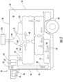
- the transport containment assembly 26 further includes a plurality of boxes 52 that may be modular, a refrigerated air supply duct 54 and an air return duct 56.
- the refrigeration unit 36 may include a compressor 58, a condenser 60, an expansion valve 62, an evaporator 64, and an evaporator fan or blower 66.
- the compressor 58 may be powered by an electrical generator driven by an engine system (not shown).
- the fan 66 drives cooling air (see arrows 68) through the evaporator 64, through the supply duct 54 and into the boxes 52. From the boxes 52, the cooling air returns to the refrigeration unit 36 via the return duct 56.
- the boxes 52 are aligned in series with one-another such that cooling air 68 flows from a leading box 70 and to the next adjacent box.
- the cooling air 68 flows from one cooling box to the next adjacent cooling box, and until the cooling air flows through a trailing box 72.
- the cooling air 68 flows through the return duct 56 and back to the refrigeration unit 36.
- the supply duct 54 and the return duct 56 may be flexible and are detachably engaged to the respective leading and trailing boxes 70, 72, and each box 52 is detachably engaged, and in fluid communication with, the next adjacent box for the flow of cooling air 68.
- the boxes 52 are stacked and sorted for easy removal of one box from the remaining boxes once the box has reach its delivery destination.
- the plurality of boxes 52 are stacked in a multitude of rows.
- the shape and size of the boxes 52 may vary along with the height of each row and may be dependent, at least in-part, on the shape and/or various contours of the compartment 50.
- each box 52 may be thermally insulated and may include opposite side walls 74, 76, opposite end walls 78, 80, a bottom wall 82, and a top wall 84.
- the walls 74, 76, 78, 80, 82, 84 together define the boundaries of a thermally insulated cavity 86 for the storage and transport of cargo 88 that may require refrigeration.
- the end walls 78, 80 include at least one inlet port 90 with an associated first isolation device 92 and at least one outlet port 94 with an associated second isolation device 96.
- the first and second isolation devices 92, 96 are configured to close when the associated boxes 52 are removed from the transport container 34 (or are otherwise not associated with an adjacent box). With the box 52 removed from the container 34 and no longer in fluid communication with the remaining boxes, closure of the isolation devices 92, 96 in the thermally insulated box 52 preserves the cold environment of the cavity 86.
- an alignment feature 98 is generally carried between adjacent boxes 52 and may be associated with, or proximate to, the respective inlet and outlet ports 90, 94.
- the alignment feature 98 may include a collar 100 that projects outward from a leading end wall 80 of a trailing box 52, and a counter bore 102 in a trailing end wall 78 of the adjacent leading box.
- the collar 100 may define the boundaries of the inlet port 90 in the leading end wall 80, and the counter bore 102 (in the trailing end wall 78 of the adjacent leading box) may be concentric to and in fluid communication with the outlet port 94 in the same trailing end wall 78.
- the collar 100 projecting outward from the leading end wall 80 of the trailing box, may fit snugly into the counter bore 102 in the trailing end wall 78 of the leading box.
- the isolation device 92 may include a damper 104 pivotally connected to the collar 100 and configured to be pivotally biased in a closed position (i.e. closes-off the inlet port 90).
- the damper 104 may be biased toward the closed position by a resilient member 106 that may be a spring.
- a force created by a differential pressure across the inlet port 90 i.e., induced by the cooling air 68 flow) may be sufficient to overcome the biasing force of the resilient member 106 and thereby open the isolation device 92.
- the isolation device 90 for the outlet port 94 may include a shutter 108 that is manually slid over the outlet port 86 when the associated box 52 is removed from the container 34.
- each end wall 78, 80 of each box 52 may include both inlet and outlet ports 90, 94 for versatility of positioning the boxes 52 within the container 34.
- the bottom and top walls 82, 84 may have similar inlet and outlet ports for the flow of cooling air 68 between rows of boxes 52 (see FIG. 2 ) and detachable engagement of the supply and/or return ducts 54, 56.
- the isolation devices 92, 96 may be mechanically actuated and may be mechanically actuated by the act of coupling one box 52 to the next adjacent box (i.e., act of indexing one box 52 to the next adjacent box).
- the isolation devices 92, 96 may be identical and the inlet and outlet ports 90, 94 may be the same (i.e., direction of airflow through ports 90, 94 is dependent upon the positioning of the box 52).
- the boxes 52 may be stacked directly adjacent to one another with the top wall 84 of a lower box in contact with a bottom wall 82 of an upper box.
- An indexing feature 110 may be carried between the upper and lower boxes 52 that aligns the boxes axially with respect to centerlines 112 of the coupling inlet and outlet ports 90, 94.
- the indexing feature 110 may further guide the coupling of leading and trailing boxes.
- the indexing feature 110 may include at least one rail 114 (i.e. two illustrated) and at least one groove 116 for sliding receipt of the rail 114.
- the rail 114 i.e., two illustrated
- the rail 114 may be defined by the contours of an external, bottom, surface 118 carried by the top bottom wall 82.
- the groove 116 may have boundaries defined by the contours of an external, top, surface 120 carried by the top wall 84. It is further contemplated and understood the location of the rails 114 and grooves 116 may be interchanged.
- each modular box 52 may include a temperature sensor 122 that outputs a temperature signal 124 to an electronic, central, device 126 that may monitor and record temperatures within each box and/or may utilized the temperature signal 124 to, at least in-part, control the refrigeration unit 36. It is further contemplated and understood that not all boxes may require temperature sensors 122. Moreover and for the purpose of controlling the refrigeration unit 36, the temperature sensor(s) may be located in the supply and/or return ducts 54, 68 (not shown).
Claims (14)
- Ensemble conteneur de transport (28) comprenant :une unité de réfrigération (36) ;un conteneur (34) ; etune pluralité de caisses (52) de stockage de marchandises ;caractérisé en ce que la pluralité de caisses est configurée en série les unes avec les autres et empilée en une multitude de rangées pour permettre l'écoulement de l'air de refroidissement provenant de l'unité de réfrigération,dans lequel les caisses adjacentes de la pluralité de caisses sont en prise de manière amovible les unes avec les autres ;et dans lequel chacune de la pluralité de caisses comporte un orifice d'entrée (90) et un orifice de sortie (94) pour permettre l'écoulement de l'air de refroidissement, et dans lequel chacune de la pluralité de caisses comporte un premier dispositif d'isolation (92) réalisé et agencé pour fermer l'orifice d'entrée et un second dispositif d'isolation (96) réalisé et agencé pour fermer l'orifice de sortie,dans lequel chacune de la pluralité de caisses définit une cavité (86) et chaque cavité des caisses adjacentes est en communication fluidique les unes avec les autres.
- Ensemble conteneur de transport selon la revendication 1, dans lequel chacune des caisses de la pluralité de caisses est isolée.
- Ensemble conteneur de transport selon l'une quelconque des revendications 1 ou 2, comprenant également :
un conduit d'alimentation (54) en communication fluidique entre l'unité de réfrigération et une caisse avant (70) de la pluralité de caisses. - Ensemble conteneur de transport selon la revendication 3, dans lequel le conduit d'alimentation (54) est relié de manière amovible à la caisse avant (70).
- Ensemble conteneur de transport selon une quelconque revendication précédente, comprenant également :
un conduit de retour (56) en communication fluidique entre l'unité de réfrigération et une caisse arrière (72) de la pluralité de caisses. - Ensemble conteneur de transport selon la revendication 5, dans lequel le conduit de retour (56) est relié de manière amovible à la caisse arrière (72).
- Ensemble conteneur de transport selon l'une quelconque des revendications 1 ou 2, comprenant également :un conduit d'alimentation (54) en communication fluidique entre l'unité de réfrigération et une caisse avant (70) de la pluralité de caisses, et dans lequel le conduit d'alimentation est relié de manière amovible à la caisse avant ; etun conduit de retour (56) en communication fluidique entre l'unité de réfrigération et une caisse arrière (72) de la pluralité de caisses, et dans lequel le conduit de retour est relié de manière amovible à la caisse arrière.
- Ensemble conteneur de transport selon une quelconque revendication précédente, dans lequel au moins une partie de la pluralité de caisses comporte un capteur de température (122) pour mesurer la température de l'air de refroidissement.
- Ensemble conteneur de transport selon une quelconque revendication précédente, dans lequel chacune de la pluralité de caisses comporte une surface supérieure profilée et une surface inférieure profilée pour empiler et guider la pluralité de caisses les unes sur les autres.
- Ensemble conteneur de transport selon la revendication 9, dans lequel l'une des surfaces supérieure et inférieure comporte au moins une rainure (116) et l'autre des surfaces supérieure et inférieure comporte au moins un rail (14) destiné à être reçu dans la rainure.
- Ensemble conteneur de transport selon la revendication 10, dans lequel les rainures et les rails s'étendent longitudinalement dans la direction de prise de la caisse.
- Ensemble conteneur de transport selon une quelconque revendication précédente,dans lequel le premier dispositif d'isolation comporte un amortisseur pivotant (104) et un élément élastique (106), dans lequel l'amortisseur pivotant est sollicité dans une position fermée par l'élément élastique, éventuellementdans lequel l'écoulement de l'air de refroidissement produit une pression différentielle à travers l'amortisseur pivotant suffisante pour ouvrir le premier dispositif d'isolation.
- Ensemble conteneur de transport selon la revendication 12, dans lequel le second dispositif d'isolation comporte un obturateur (108) réalisé et agencé pour coulisser sur l'orifice de sortie.
- Ensemble conteneur de transport selon une quelconque revendication précédente, comprenant également :
un élément d'alignement (90) placé entre des première et seconde caisses adjacentes de la pluralité de caisses pour aligner l'orifice de sortie de la première caisse avec l'orifice d'entrée de la seconde caisse.
Applications Claiming Priority (1)
| Application Number | Priority Date | Filing Date | Title |
|---|---|---|---|
| PCT/IB2015/002118 WO2017068384A1 (fr) | 2015-10-22 | 2015-10-22 | Boîtes froides modulaires pour unité de réfrigération pour le transport |
Publications (2)
| Publication Number | Publication Date |
|---|---|
| EP3365622A1 EP3365622A1 (fr) | 2018-08-29 |
| EP3365622B1 true EP3365622B1 (fr) | 2024-04-10 |
Family
ID=54695767
Family Applications (1)
| Application Number | Title | Priority Date | Filing Date |
|---|---|---|---|
| EP15798187.9A Active EP3365622B1 (fr) | 2015-10-22 | 2015-10-22 | Ensemble conteneur de transport |
Country Status (5)
| Country | Link |
|---|---|
| US (1) | US11378324B2 (fr) |
| EP (1) | EP3365622B1 (fr) |
| CN (1) | CN108139134A (fr) |
| SG (1) | SG11201802903SA (fr) |
| WO (1) | WO2017068384A1 (fr) |
Families Citing this family (4)
| Publication number | Priority date | Publication date | Assignee | Title |
|---|---|---|---|---|
| CN108088140B (zh) * | 2017-11-06 | 2020-06-23 | 青岛海尔股份有限公司 | 一种自收容式层叠冰箱 |
| CN108088139B (zh) * | 2017-11-06 | 2020-05-26 | 青岛海尔股份有限公司 | 层叠式冰箱 |
| CN108120206B (zh) * | 2018-02-27 | 2020-06-23 | 青岛海尔股份有限公司 | 冰箱 |
| US20220373249A1 (en) * | 2019-11-15 | 2022-11-24 | Biomarin Pharmaceutical Inc. | Secondary container with flow-through apertures for freezing, thawing, and shipping products, and associated methods |
Citations (4)
| Publication number | Priority date | Publication date | Assignee | Title |
|---|---|---|---|---|
| EP0254947A2 (fr) * | 1986-07-17 | 1988-02-03 | Del Monte Fresh Fruit Company (unit of Nabisco Brands, Inc.) | Procédé et appareil de contrôle du mûrissement de produits frais |
| JPS6334472A (ja) * | 1986-03-04 | 1988-02-15 | 株式会社デンソー | 冷蔵装置 |
| CN101482354A (zh) * | 2008-01-10 | 2009-07-15 | 陈瑞照 | 组合式冰箱 |
| WO2014104985A1 (fr) * | 2012-12-24 | 2014-07-03 | Bračič Aleš | Dispositif et procédé de conditionnement de denrées alimentaires |
Family Cites Families (29)
| Publication number | Priority date | Publication date | Assignee | Title |
|---|---|---|---|---|
| US3275188A (en) * | 1965-01-18 | 1966-09-27 | Banner Metals Inc | Receptacle |
| US3477243A (en) * | 1968-01-04 | 1969-11-11 | Adolph C Schroeder | Refrigerating system |
| GB1495382A (en) | 1973-12-10 | 1977-12-14 | Shipowners Cargo Res Assoc | Transport containers |
| US4003728A (en) * | 1974-10-09 | 1977-01-18 | Eric Rath | Method and apparatus for controlling the storage condition of perishable commodities in long-distance transport vehicles |
| SE399541B (sv) | 1975-10-03 | 1978-02-20 | Stal Refrigeration Ab | Anordning for upprettande och brytande av en fluidumforbindelse mellan tvenne utrymmen |
| SE415208B (sv) | 1975-10-16 | 1980-09-15 | Stal Refrigeration Ab | Stationert anordnat anslutningsdon for att ansluta en oppning hos en flyttbar lastbehallare till en luftkonditioneringsanleggning |
| DE3134987A1 (de) * | 1981-09-04 | 1983-03-17 | Lothar 4010 Hilden Jäger | Camping-kuehlboxsystem |
| FR2580061A1 (en) * | 1985-04-09 | 1986-10-10 | Armel Louis | Improvements to refrigerators and freezers |
| EP0258320A4 (fr) | 1986-02-21 | 1988-06-27 | Tcs Containers Pty Ltd | Conteneurs pour cargaisons. |
| JPS63180061A (ja) * | 1987-01-20 | 1988-07-25 | 株式会社デンソー | 冷蔵装置 |
| FR2677000A1 (fr) | 1991-05-29 | 1992-12-04 | Pralus Georges | Conditionnement calorifuge pour le transport refrigere ou chaud de recipients contenant des produits alimentaires. |
| US5531158A (en) * | 1994-05-16 | 1996-07-02 | Perryman, Jr.; Owen J. | Produce ripening apparatus and method |
| US5649432A (en) | 1996-06-14 | 1997-07-22 | Cavalea, Iii; Anthony C. | Portable temperature-controlled unit with moveably attached insulation |
| US6443309B1 (en) * | 2000-05-15 | 2002-09-03 | Victory Packaging, Inc. | Apparatus for packaging goods |
| US7913513B1 (en) | 2002-01-22 | 2011-03-29 | Thermal Technologies, Inc. | Retail banana storage unit |
| US20040178161A1 (en) | 2003-03-13 | 2004-09-16 | Svetlana Galustyan | Interconnecting container assembly |
| US6901768B1 (en) * | 2004-05-30 | 2005-06-07 | Robert J. Windecker | Environmentally controlled storage and ripening apparatus |
| US20060113302A1 (en) | 2004-09-09 | 2006-06-01 | Inteligistics, Inc. | Modular shipping unit and system |
| EP1861669A1 (fr) * | 2005-03-23 | 2007-12-05 | Coldway Societe Anonyme | Conteneur amovible isotherme, refrigere ou chauffe |
| CN101003323B (zh) * | 2006-01-16 | 2010-05-12 | 中国国际海运集装箱(集团)股份有限公司 | 智能冷藏集装箱 |
| US20090242579A1 (en) | 2008-04-01 | 2009-10-01 | Kai-Cheng Huang | Membrane-type vented food box |
| US20100224624A1 (en) * | 2009-03-05 | 2010-09-09 | Homer Gonzalez | Container interconnect |
| CN104302992B (zh) * | 2011-06-16 | 2016-11-09 | 马士基航运公司 | 冷藏运输集装箱中的内部空气循环控制 |
| US20130111726A1 (en) | 2011-11-07 | 2013-05-09 | Glenn D. Krieger | Modular insulated container system |
| JP5436522B2 (ja) * | 2011-11-25 | 2014-03-05 | 三菱電機株式会社 | 冷凍冷蔵庫 |
| US20130146272A1 (en) * | 2011-12-13 | 2013-06-13 | Ronald E. Jackson | Barometric relief air zone damper |
| DE102012213542A1 (de) | 2012-08-01 | 2014-02-06 | Goselig UG | Kältespeichervorrichtung sowie Kühlanlagenanordnung |
| JP5878983B2 (ja) * | 2012-09-26 | 2016-03-08 | ジャパン サイエンス アンド テクノロジー トレーディング カンパニー リミテッドJapan Science & Technology Trading Co.,Limited | 機能性連続急速冷凍装置 |
| US20150316311A1 (en) * | 2014-05-02 | 2015-11-05 | Thermo King Corporation | Multi-temperature transport refrigeration system |
-
2015
- 2015-10-22 US US15/769,147 patent/US11378324B2/en active Active
- 2015-10-22 EP EP15798187.9A patent/EP3365622B1/fr active Active
- 2015-10-22 WO PCT/IB2015/002118 patent/WO2017068384A1/fr active Application Filing
- 2015-10-22 SG SG11201802903SA patent/SG11201802903SA/en unknown
- 2015-10-22 CN CN201580084019.1A patent/CN108139134A/zh active Pending
Patent Citations (4)
| Publication number | Priority date | Publication date | Assignee | Title |
|---|---|---|---|---|
| JPS6334472A (ja) * | 1986-03-04 | 1988-02-15 | 株式会社デンソー | 冷蔵装置 |
| EP0254947A2 (fr) * | 1986-07-17 | 1988-02-03 | Del Monte Fresh Fruit Company (unit of Nabisco Brands, Inc.) | Procédé et appareil de contrôle du mûrissement de produits frais |
| CN101482354A (zh) * | 2008-01-10 | 2009-07-15 | 陈瑞照 | 组合式冰箱 |
| WO2014104985A1 (fr) * | 2012-12-24 | 2014-07-03 | Bračič Aleš | Dispositif et procédé de conditionnement de denrées alimentaires |
Also Published As
| Publication number | Publication date |
|---|---|
| US11378324B2 (en) | 2022-07-05 |
| EP3365622A1 (fr) | 2018-08-29 |
| WO2017068384A1 (fr) | 2017-04-27 |
| US20180306480A1 (en) | 2018-10-25 |
| CN108139134A (zh) | 2018-06-08 |
| SG11201802903SA (en) | 2018-05-30 |
Similar Documents
| Publication | Publication Date | Title |
|---|---|---|
| EP3365622B1 (fr) | Ensemble conteneur de transport | |
| US6895764B2 (en) | Environmentally friendly method and apparatus for cooling a temperature controlled space | |
| US6694765B1 (en) | Method and apparatus for moving air through a heat exchanger | |
| JPH06507702A (ja) | 冷凍コンテナー | |
| US20070251685A1 (en) | Temperature control system and method for operating the same | |
| EP3311085B1 (fr) | Unité de réfrigération de transport et son procédé d'opération | |
| US9132765B2 (en) | Trailer refrigerating apparatus | |
| EP2847528B1 (fr) | Dispositif de sortie d'air pour un conteneur réfrigéré | |
| US20160231043A1 (en) | Air intake for refrigerated container assembly | |
| CN112739964A (zh) | 制冷剂泄漏检测系统 | |
| CN101520273A (zh) | 冷冻柜的保冷运转控制装置 | |
| EP3320282B1 (fr) | Unité de réfrigération de transport | |
| WO2017147299A1 (fr) | Système actif pour régulation de température et mélange d'air améliorés à l'intérieur de conteneurs intermodaux, de remorques et de caisses de camions frigorifiques | |
| US20160176263A1 (en) | Air conditioning system for tractor trailers | |
| US10365027B2 (en) | Simplified and energy efficient multi temperature unit | |
| EP4283805A2 (fr) | Système de stockage d'énergie de réfrigération de transport | |
| EP3271210B1 (fr) | Écran thermique et anti-poussière | |
| EP3180574B1 (fr) | Espaceur d'un évaporateur à conduit d'air | |
| US20230373376A1 (en) | Transport refrigeration energy storage system mounting system | |
| US20230271482A1 (en) | Transport refirgeration system for high ambient operation | |
| CN115771381A (zh) | 用于制冷系统的can总线适配器 |
Legal Events
| Date | Code | Title | Description |
|---|---|---|---|
| STAA | Information on the status of an ep patent application or granted ep patent |
Free format text: STATUS: THE INTERNATIONAL PUBLICATION HAS BEEN MADE |
|
| PUAI | Public reference made under article 153(3) epc to a published international application that has entered the european phase |
Free format text: ORIGINAL CODE: 0009012 |
|
| STAA | Information on the status of an ep patent application or granted ep patent |
Free format text: STATUS: REQUEST FOR EXAMINATION WAS MADE |
|
| 17P | Request for examination filed |
Effective date: 20180502 |
|
| AK | Designated contracting states |
Kind code of ref document: A1 Designated state(s): AL AT BE BG CH CY CZ DE DK EE ES FI FR GB GR HR HU IE IS IT LI LT LU LV MC MK MT NL NO PL PT RO RS SE SI SK SM TR |
|
| AX | Request for extension of the european patent |
Extension state: BA ME |
|
| DAV | Request for validation of the european patent (deleted) | ||
| DAX | Request for extension of the european patent (deleted) | ||
| STAA | Information on the status of an ep patent application or granted ep patent |
Free format text: STATUS: EXAMINATION IS IN PROGRESS |
|
| 17Q | First examination report despatched |
Effective date: 20190607 |
|
| STAA | Information on the status of an ep patent application or granted ep patent |
Free format text: STATUS: EXAMINATION IS IN PROGRESS |
|
| GRAP | Despatch of communication of intention to grant a patent |
Free format text: ORIGINAL CODE: EPIDOSNIGR1 |
|
| STAA | Information on the status of an ep patent application or granted ep patent |
Free format text: STATUS: GRANT OF PATENT IS INTENDED |
|
| INTG | Intention to grant announced |
Effective date: 20231201 |
|
| GRAS | Grant fee paid |
Free format text: ORIGINAL CODE: EPIDOSNIGR3 |
|
| GRAA | (expected) grant |
Free format text: ORIGINAL CODE: 0009210 |
|
| STAA | Information on the status of an ep patent application or granted ep patent |
Free format text: STATUS: THE PATENT HAS BEEN GRANTED |
|
| AK | Designated contracting states |
Kind code of ref document: B1 Designated state(s): AL AT BE BG CH CY CZ DE DK EE ES FI FR GB GR HR HU IE IS IT LI LT LU LV MC MK MT NL NO PL PT RO RS SE SI SK SM TR |
|
| REG | Reference to a national code |
Ref country code: GB Ref legal event code: FG4D |
|
| REG | Reference to a national code |
Ref country code: CH Ref legal event code: EP |