EP3365122B1 - Installation de production pour la production de pièces en tôle - Google Patents
Installation de production pour la production de pièces en tôle Download PDFInfo
- Publication number
- EP3365122B1 EP3365122B1 EP16781462.3A EP16781462A EP3365122B1 EP 3365122 B1 EP3365122 B1 EP 3365122B1 EP 16781462 A EP16781462 A EP 16781462A EP 3365122 B1 EP3365122 B1 EP 3365122B1
- Authority
- EP
- European Patent Office
- Prior art keywords
- bending
- support
- bending tool
- tool
- working edge
- Prior art date
- Legal status (The legal status is an assumption and is not a legal conclusion. Google has not performed a legal analysis and makes no representation as to the accuracy of the status listed.)
- Not-in-force
Links
Images


Classifications
-
- B—PERFORMING OPERATIONS; TRANSPORTING
- B21—MECHANICAL METAL-WORKING WITHOUT ESSENTIALLY REMOVING MATERIAL; PUNCHING METAL
- B21D—WORKING OR PROCESSING OF SHEET METAL OR METAL TUBES, RODS OR PROFILES WITHOUT ESSENTIALLY REMOVING MATERIAL; PUNCHING METAL
- B21D5/00—Bending sheet metal along straight lines, e.g. to form simple curves
- B21D5/04—Bending sheet metal along straight lines, e.g. to form simple curves on brakes making use of clamping means on one side of the work
-
- B—PERFORMING OPERATIONS; TRANSPORTING
- B30—PRESSES
- B30B—PRESSES IN GENERAL
- B30B15/00—Details of, or accessories for, presses; Auxiliary measures in connection with pressing
- B30B15/007—Means for maintaining the press table, the press platen or the press ram against tilting or deflection
-
- B—PERFORMING OPERATIONS; TRANSPORTING
- B21—MECHANICAL METAL-WORKING WITHOUT ESSENTIALLY REMOVING MATERIAL; PUNCHING METAL
- B21D—WORKING OR PROCESSING OF SHEET METAL OR METAL TUBES, RODS OR PROFILES WITHOUT ESSENTIALLY REMOVING MATERIAL; PUNCHING METAL
- B21D5/00—Bending sheet metal along straight lines, e.g. to form simple curves
- B21D5/02—Bending sheet metal along straight lines, e.g. to form simple curves on press brakes without making use of clamping means
- B21D5/0272—Deflection compensating means
Definitions
- the invention relates to a manufacturing plant for the production of workpieces made of sheet metal, in particular by forming, by means of a bending machine.
- the EP 2 127 772 A2 describes a machine for forming flat workpieces along an elongate tool.
- the forming machine comprises a tool carrier, which is held on both sides in a machine frame and can be moved relative to it, with the tool being held in a tool-receiving manner in a tool holder.
- the tool carrier is equipped along its length with several actuators, which act on the tool from the side facing away from the workpiece.
- Each of the adjusting elements is formed by a hydraulic cylinder, wherein the hydraulic cylinders are hydraulically connected to each other such that during the forming process along the tool sets a substantially uniform contact pressure to the workpiece. In this adjustment system could only be carried out an adjustment of the tool in the direction of its width or height in a parallel direction with respect to the bending cheek.
- a bending machine and a method for compensating the bending of parts of the bending machine have become known.
- the compensation of the deflection of the bending machine relates in particular to the table and / or the plunger and / or tools thereof, wherein relatively movable wedges are shifted more or less relative to each other depending on the extent of the desired compensation or the crowning.
- a force is exerted before the displacement by which at least one of the wedges is relieved or lifted and that thereafter carried out the relative displacement and then the relief or lifting force is reduced or canceled or turned off.
- the disadvantage here is that a separate lifting system for relieving the individual wedges must be provided in order to then adjust the relative position of the wedges to each other with a further adjustment.
- the DE 10 2006 047 108 A1 describes a bending machine for bending flat material, which comprises a machine frame, a top cheek, a lower cheek and a bending cheek pivoting about a geometric axis with respect to the upper cheek and the lower cheek and carrying a bending tool. Between the upper beam and the lower beam, the sheet is clamped to bending. In order to improve the deflection of the bending beam during the bending process, it is proposed here that this has a support cheek extending over at least the entire bending beam length and a tool carrier cheek carrying the bending tool.
- the tool support cheek is constantly supported by two support bearings on the support cheek.
- the support bearings are arranged at a smaller distance from each other than a total distance between end sides of the tool carrier cheek.
- the object of the present invention was to overcome the disadvantages of the prior art and to provide a device by means of which a user is able to provide a mutually differently curved longitudinal course of the working edge of the bending tool by a simple adjusting movement. Furthermore, the adjusting movement should be carried out with less effort to deform the working edge.
- the advantage achieved thereby lies in the fact that a simple adjusting device can be created in which, depending on the selected adjustment direction, a mutually different deformation of the working edge of the bending tool in the direction of its longitudinal extent can be achieved.
- a corresponding adjusting force can be applied to the bending tool in the longitudinal sections provided in order to be able to define and set the curved longitudinal course of the working edge of the bending tool for the respective bending process.
- the adjustment of the one or more adjusting elements takes place by means of the actuator in a simple relative mostly rectilinear adjustment, which has an orientation which is aligned in the direction of the longitudinal extension of the bending tool. Furthermore, so can be found even with low adjustment paths Ausmaschine.
- the bending tool prefferably has at least one free position on its flat side facing the tool carrier, and to form a first contact surface and a second contact surface on both sides of the relief, and the second contact surface is formed in the region of an end that is distanced from the working edge and that the bending tool is supported with its first contact surface on the actuator and its second contact surface on the support member or the bending tool is supported with its first contact surface on the support member and its second contact surface on the tool carrier and the displacement of the working edge of the bending tool takes place by a pivoting movement of the working edge of the bending tool about a pivot radius, whose pivot center is arranged in the region of the second contact surface.
- a combined, superimposed adjustment movement of the working edge can be achieved by this pivoting movement.
- a spatial curvature of the bending tool can be achieved in the region of its working edge, whereby both an adjustment in the "X" direction and at the same time an additional adjustment in the "Y” direction can be achieved.
- first support surfaces and a plurality of second support surfaces are arranged or formed on the at least one actuating element and on the at least one support element on respectively facing and oppositely disposed surface sections, and that each of the first support surfaces has a first and a second support surface section each of the second support surfaces having a third and a fourth support surface portion, wherein both the first and second support surface portion and the third and fourth support surface portion seen in the adjustment direction of the adjusting element are arranged immediately adjacent to each other, and that each of the first and second support surface portion below a first Angle and / or the respective third and fourth support surface portion at a second angle inclined to each other are aligned.
- a further embodiment provides that at least some of the first and second support surface portions of the first support surfaces are arranged on the at least one actuating element extending in the direction of the longitudinal extension of the bending tool with a different inclination direction with respect to the machine plane.
- Another embodiment is characterized in that the first support surface sections are aligned in a central region of the longitudinal extent of the bending tool approximately parallel to the machine plane running. This can be carried out at a correspondingly selected adjustment a mutually parallel adjustment between the actuator and the support element, without causing a lateral or transverse displacement of the bending tool, whereby no displacement and thus no deformation of the working edge of the bending tool is performed.
- a further preferred embodiment is characterized in that the first support surface sections, starting from the central region of the bending tool in each case in the direction of both end regions of the bending tool with increasing distance include a larger inclination angle with the machine plane. This can be increased in accordance with selected adjustment direction with increasing distance or distance from the central region, the extent of deformation and the associated curvature.
- the second support surface sections in the two end regions of the bending tool are aligned approximately parallel with respect to the machine plane.
- the possibility is also created here to be able to perform a mutually parallel adjustment between the actuator and the support member at a correspondingly selected adjustment only.
- Another alternative embodiment is characterized in that the second support surface sections, starting from the two end regions of the bending tool in the direction of the central region, enclose a greater inclination angle with the machine plane with increasing distance.
- the extent of deformation of the bending tool and, associated therewith, a greater curvature can likewise be achieved starting from the two end regions in the direction of the middle region, again with a correspondingly selected adjustment direction of the adjusting element or elements.
- angle of inclination between the first support surface sections and the machine plane has a value selected from a range between 0 ° and 3 °, in particular between 0 ° and 1.5 °. So can by the choice of the angle of inclination on the one hand the applied adjusting force and on the other hand the extent of the displacement are determined.
- a further embodiment provides that the angle of inclination between the second support surface sections and the machine plane in each case has a value which is selected from a range between 0 ° and 3 °, in particular between 0 ° and 1.5 °.
- the desired deformation value of the working edge of the bending tool can also be predetermined here.
- first and second support surface sections include a first angle between them, which has a value which is smaller than 180 °. This can be achieved between immediately adjacent support surface sections a kink and thus the formation of a ramp.
- a further preferred embodiment is characterized in that at least some of the third and fourth support surface portions each include a second angle therebetween having a value equal to or less than 180 °.
- the third and fourth contact surface sections each enclose a second angle between them, which has a value which is greater than 180 °. This can be created in intermediate areas between the central region and the two left and right end regions another variant leadership.
- Another embodiment is characterized in that the adjusting device seen in the direction of the longitudinal extent of the working edge on both sides of the at least one adjusting element each comprises a fixed in the direction of the longitudinal extent of the tool carrier first and second support member.
- Another possible and optionally alternative embodiment has the features that in the longitudinal extension of the bending tool a plurality, in particular two, successively arranged adjusting devices are provided which are each independently adjustable. Thus, an even more individual adjustment of the bending tool and thus an even more individual deformation process can be performed.
- a further embodiment provides that each of the adjusting devices in the longitudinal extension of the bending tool at least two successively arranged adjusting elements and two consecutively arranged second support elements comprises and each have their first and second support surfaces to each other an opposite direction of inclination with respect to the machine plane. This in turn creates the possibility, depending on the selected adjustment either to deform the central region of the bending tool or at least one of the two end portions.
- the bending tool is supported in the starting position with still undeformed, rectilinear working edge at least in the region of the second support elements in the vertical direction with respect to the machine plane via at least one spacer element directly on the bending beam. This can be achieved in each case a safer and stable zero position of the bending tool and associated rectilinear alignment of the working edge.
- the adjusting device further comprises a plurality of rolling elements with a rotationally symmetrical spatial form, wherein the rolling elements between or facing surface portions of the at least one actuating element and the support element or the support elements is or are arranged.
- the spatial form of the rolling elements from the group of ball, cylinder, hollow cylinder, cone, truncated cone is selected.
- Another embodiment is characterized, when seen in cross-section, which are arranged curved or curved on the one or more adjusting elements and / or the support elements or trained support surfaces and / or longitudinal guide surfaces. As a result, an even more targeted longitudinal guidance can be achieved in the area of the rolling bodies on the surface sections facing them.
- a further preferred embodiment is characterized in that the rolling elements each arranged between the at least one adjusting element and the at least one supporting element are held in a separate cage. As a result, the rolling elements can always be held and guided relative to one another in a positioned position.
- the bending tool in its longitudinal extent several times on the bending beam, in particular the at least one support element is fixed.
- the at least one support element is fixed.
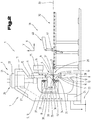
- a production plant 1 is shown in a highly schematically simplified representation, which is formed in the present case in particular for the swivel bending or bending of bending to be produced from sheet metal workpieces 2.
- a metallic material is usually used, which can be referred to in its undeformed state as a flat material or flat element.
- the manufacturing plant 1 used in the present case for bending and described in more detail comprises a bending machine 3, in particular a folding machine, which is designed for clamping the workpieces 2 or workpieces to be produced from the sheet metal between a clamping tool 4 which is adjustable relative to one another.
- the clamping tool 4 comprises in the present embodiment, at least one, but preferably a plurality of lower jaws 5 and at least one, but preferably more cooperating upper jaws 6.
- the lower jaw or 5 can also be part of the lower cheek and the or the upper jaws. 6 can also be referred to as part of the upper cheek.
- the at least one upper clamping jaw 6 is arranged above the workpiece 2 to be manufactured on the bending machine 3 and held there accordingly, in particular clamped. Also, the at least one lower jaw 5 is held on the bending machine 3, in particular clamped.
- a machine frame 7 of the bending machine 3 comprises, for example, vertically upstanding from a base plate 8 and mutually parallel side cheeks 9, 10. These are preferably interconnected by a solid, formed for example of a sheet metal part cross member 11 at their spaced from the bottom plate 8 end regions ,
- the machine frame 7 is usually a solid, preferably on a flat hall floor fixed component of the bending machine 3.
- the shape shown here has been chosen only as an example for a variety of other possible training.
- the side cheeks 9, 10 may be formed to form a clearance for the forming of the workpiece 2 preferably in approximately C-shaped, wherein attached to front end faces 12 of bottom flanges of the side cheeks 9, 10 a fixed, in particular on the bottom plate 8 upstanding lower clamping bar 13 is, which can also be referred to as a pressing bar.
- This preferably fixedly arranged and fixed lower clamping bar 13 may also be referred to as a clamping table or as a lower beam, are arranged on the parts of the clamping tool 4 and also held thereon.
- a further upper clamping bar 16 in particular a pressure bar, which is relatively adjustable relative to the lower clamping bar 13, is guided on the leg remote from the base plate 8 in clamping bar guides 15.
- the clamping bar guides 15 are usually designed as linear guides in a variety of embodiments.
- this further clamping bar 16 may be referred to as a press beam or as a top beam, which, however, relative to the machine frame 7 is displaceably guided on this.
- jaw receiving 19, 20 are arranged for assembly with the clamping tools 4.
- the or the clamping tools 4 can also be held with the interposition of an adapter not shown on the jaw receiving 19, 20.
- the bending machine 3 shown has, as a drive arrangement 21 for the adjustable upper clamping bar 16, namely the pressure bar, at least one drive means 22 operated with electrical energy, which are line-connected to a control device 24 fed from a power grid 23.
- the operation of the bending machine 3 can be controlled via a line-connected input terminal 25 connected to the control device 24.
- the drive means 22 are preferably electromotively operated spindle drives 26, as they are generally known, of which adjusting means 27 for a reversible actuating movement of the upper clamping bar 16 formed by the pressure bar with this, for example, are drive-connected.
- adjusting means 27 for a reversible actuating movement of the upper clamping bar 16 formed by the pressure bar with this, for example, are drive-connected.
- other drive means 22 known from the prior art such as e.g. Cylinder piston assemblies, stepper motors, rack drives or the like can be used.
- the two clamping bars 13, 16, in particular their tool holders 19, 20, and the clamping tool 4 held thereon with his or its lower and upper jaws 5, 6, when viewed in the longitudinal direction of the clamping bars 13, 16 define an adjustment plane or machine plane 28 extending therebetween.
- the adjustment plane or the machine plane 28 preferably extends centrally with respect to the clamping bars 13, 16 or the jaw receivers 19, 20 arranged on them.
- a vertically oriented plane is understood here.
- the adjustment plane or the machine plane 28 can also be referred to as the reference plane for the bending tool 37 located in its vertical orientation.
- the machine plane 28 also subsequently forms a reference or reference plane for a bending tool 37 of a bending unit 35.
- the two jaws 5, 6 form a clamping region 29 between them at mutually facing ends.
- Mutually facing lower and upper clamping surfaces 30, 31 of the two clamping jaws 5, 6 are preferably aligned at right angles with respect to the adjustment plane or the machine plane 28. These clamping surfaces 30, 31 serve to keep the sheet, depending on its wall thickness for carrying out the bending operation between the two jaws 5, 6 positioned.
- An additional support table 32 with its bearing surface 33 defining a bearing surface is preferably arranged in the region of the front of the bending machine 3, which only in the Fig. 2 is indicated in simplified.
- the support plane 33 can also be referred to as a support plane. It should be noted that the support surface need not be formed over the entire surface but can also be formed from several in the feed direction of the sheet to be processed next to each other and / or successively arranged support part surfaces.
- the bearing surface 33 defined by the support surface is preferably arranged in the same plane as the lower clamping surface 30 of the lower jaw 5. This is used in larger sheets as additional support to avoid accidental kinking, especially with thinner sheets.
- a bending region 34 is understood here to be that region which serves to form the workpiece 2 to be produced from the sheet, which is usually still flat, or to further process an already pre-formed workpiece 2 by forming at least one additional fold or bend.
- the bending region 34 is usually spaced from the machine plane 28 of the clamping bar 13, 16 and is formed by mutually facing end portions of at least one, but preferably both jaws 5, 6. In the present embodiment, the bending region 34 is disposed on the side facing away from the support table 32 or an operator not shown side of the clamping bar 13, 16. Thus, the bending region 34 is arranged to extend within the machine frame 7.
- the bending region 34 usually forms a preferably rectilinear bending line on the workpiece 2 to be produced, with legs forming on both sides of the bending region 34 as a result of the bending process performed.
- One of the legs of the workpiece 2 is held in clamping position between the two clamping surfaces 30, 31 of the jaws 5, 6, wherein the at least one further leg outside of the clamping surfaces 30, 31 is arranged.
- the two legs enclose between them a bending angle. This bending angle is measured in a reference plane aligned perpendicular to the bending line.
- the reference plane for its part, is furthermore preferably also aligned with respect to the machine plane 28 in the vertical direction.
- the machine frame 7 of the bending machine 3 is shown only very simplified, and it is also possible to use different embodiments thereof. So could e.g. the machine frame 7 and the machine body may be formed with a free stator passage. In this case, the jaw receivers 19, 20 could be received between the side walls 9, 10 and side panels. In another embodiment of the machine frame 7 or of the machine body, no free stator passage is possible, as a result of which the clamping jaw receptacles 19, 20 can not be received between the side cheeks 9, 10 or side parts.
- the bending machine 3 of the production plant 1 also comprises a bending unit 35, which can also be referred to as a bending unit or forming unit.
- a bending unit 35 which can also be referred to as a bending unit or forming unit. This is simplified in the Fig. 2 indicated and can be adjusted depending on be carried out bending process relative to the machine frame 7 thereto. For better clarity, was in the Fig. 1 dispensed with the representation of the bending unit 35 and its components.
- the lower clamping jaw 5 or the upper clamping jaw 6 forms the bending area and thus the bending area 34.
- the lower clamping jaw 5 forms or has a first forming edge.
- the upper jaw 6 forms or has a second forming edge.
- the two clamping surfaces 30, 31 of the clamping jaws 5, 6 described above define a workpiece support plane 36 for the workpiece 2 to be produced.
- the workpiece support plane 36 is arranged in the vertical direction at the same height as the support plane 33 defined by the support table 32 ,
- the two planes are aligned plane-parallel to each other and arranged in a common plane.
- the bending unit 35 may have one or more bending tools 37, which may be arranged on a unspecified tool carrier of a bending beam 38, in particular be held thereto.
- the bending beam 38 may be adjustable relative to the machine frame 7 on non-illustrated bending beam guides by means of a bending beam drive relative, as shown in the Fig. 2 indicated by a double arrow.
- the main displacement direction is in the vertical direction and predominantly parallel with respect to the vertically oriented machine plane 28. This corresponds to a displacement in the direction of the "Y" direction described above.
- the manufacturing plant 1 may also include a manipulation device 39 with at least one manipulator 40, indicated in simplified fashion, for the usual manipulation of the sheet or of the workpiece 2 to be produced in the front or operating area of the bending machine 3.
- the manipulation of the sheet or of the workpiece 2 to be produced therefrom takes place in the region of the support table 32 preferably by the manipulator 40, of which only a first holding element 41 is shown on a part of a manipulator arm.
- the first holding member 41 may be or the first holding members 41 may be e.g. be designed as a suction element and / or as a magnet with which the sheet is held on its side facing away from the support plane 33 of the support table 32 side and subsequently moved relative to the clamping tool 4 and positioned relative to the bending region 34. But it would also be possible to form the first holding element 41 as a gripper with cooperating gripping rings.
- the bending tool (s) 37 are preferably continuous at least over the longitudinal extent of the bending region 34, in particular in one piece, and define an ideally rectilinear working edge 42 on their region facing the sheet or the workpiece 2 to be produced.
- the working edge 42 is in the unloaded state, so long as no bending operation is performed, to be considered to be rectilinear. Furthermore, the working edge 42 in the unloaded state should have a parallel orientation with respect to the machine plane 28 or the bending region 34 defined by the clamping jaws 5 or 6.
- This rectilinear course of the working edge 42 is changed in the course of the bending operation and the associated action of the bending tool or tools 37 as a result of the elastic deformation of the bending beam 38, in particular of the tool carrier arranged thereon. Thus, no straight course of the bending edge to be produced can be achieved on the workpiece 2.
- the bending tool 37 in the direction of its longitudinal extent - that is viewed in the direction of its working edge 42 - deformed or adjusted so that at least partially a cambered or curved longitudinal profile of the working edge 42 even before the beginning of the bending process and / or can also be set or achieved during the bending process.
- the term of the crowning or the curved longitudinal course becomes a deliberate, predetermined pre-curvature of the bending tool 37 understood in its rest position and possibly also during the bending process.
- the cambering or the adjustment to the curved longitudinal course takes place starting from an undeformed, straight longitudinal course of the working edge 42 and a preferably parallel longitudinal course of flat sides of the bending tool 37 with respect to the machine plane 28 in the workpiece support plane 36 or an output plane parallel thereto.
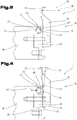
- This lateral deformation can be carried out starting from the rectilinear course of the working edge 42 and the vertical alignment of the bending tool 37 in the initial state before the beginning of the bending operation by a type of pivoting movement and optionally an associated at least partially elastic deformation of the bending tool 37 in the region of the tool carrier, as shown schematically in FIG the 3 and 4 is shown.
- the Fig. 3 shows the undeformed starting position in a side view, wherein in the Fig. 4 the adjustment performed or displacement with a pivoting radius 43 and a new position of the working edge 42 in a longitudinal section of the bending tool 37 is also shown in a side view.
- an adjusting device 44 is provided in the region of the tool carrier.
- the adjusting device 44 comprises at least one support element 45, at least one adjusting element 46 cooperating therewith, at least one adjusting element not shown in greater detail.
- a plurality of rolling elements 47 may be arranged, each having a rotationally symmetrical spatial shape.
- the rolling elements 47 may be provided, but need not be provided.
- the at least one adjusting element 46 is displaceable relative to the at least one support element 45 of the tool carrier in mutually different adjustment direction by means of the at least one actuator, wherein these in the following Fig. 5 to 7 each indicated by an arrow.
- the rolling elements 47 are also provided and shown so as to keep as small as possible to be overcome in the respective adjustment friction force.
- One of the exemptions extends from the first bearing surface 68 in the direction of the end remote from the working edge 42 and ends before this to form a second abutment surface 69th
- the bending tool 37 may further be at least partially supported in the region of its side facing away from the working edge 42 or oppositely arranged narrow side surface 72 on the tool carrier, in the present embodiment on a support member 45 formed or arranged support shoulder 73, fitting.
- a support and transmission of forces in "Y" direction, starting from the working edge 42 on the tool carrier, in particular the bending beam 38 can be achieved.
- Due to the arrangement and design of the second contact surface 69 and the narrow side surface 72, the transition region or the corner region between the second contact surface 69 and the narrow side surface 72 may form the pivot center or the base of the pivoting range for the pivoting radius 43.
- the exemption or the exemptions preferably extend over the entire longitudinal extension of the bending tool 37.
- the two contact surfaces 68, 69 are formed over the entire longitudinal extension of the bending tool 37 and thus stand for the mutual contact and support of the bending tool 37 on the tool carrier, its actuating element 46 and / or the bending beam 38, in particular the support member 45 is available. That release, which is arranged or illustrated between the first contact surface 68 and the working edge 42, may be omitted.
- the simplified indicated fastening means may be formed, for example, by a screw, in particular an expansion screw. This can be further distanced from the working edge 42 arranged second contact surface 69 or the corner region in the lower base of the bending tool 37 form the pivot center of the previously described pivoting radius 43. In addition to the lateral displacement of the working edge 42 can be achieved by the lateral pivoting movement about the pivot radius 43 in addition to a "Y" - direction - ie in a direction parallel to the machine plane 28, superimposed adjustment. However, the magnitude of this relocation is rather low.
- the lateral displacement movement in the "X" direction may be in a range between 0.0 mm and 1.0 mm, preferably up to 0.6 mm.
- the additional displacement movement in the "Y" direction may be up to 0.2 mm, preferably 0.1 mm.
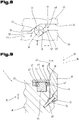
- the relative adjustment of the at least one adjusting element 46 relative to the at least one support element 45 takes place in the direction of the longitudinal extent of the working edge 42, this starting from an undeformed starting position of the working edge 42- like this in the Fig. 5 is shown - depending on the selected adjustment to the respective indicated longitudinal course of the working edge 42 according to the examples shown in the Fig. 6 and 7 leads.
- the at least one adjusting element 46 can be adjusted relative to the support element 45, starting from a basic position both in a first adjustment direction and in a second adjustment direction oppositely directed or extending thereto.
- the longitudinal course of the working edge 42 is rectilinear and can optionally be deformed depending on the direction of inclination of the cooperating support or support surfaces of the support element 45 and the adjusting element 46.
- the spatial form of the rolling elements 47 may be selected from the group of sphere, cylinder, hollow cylinder, cone, truncated cone.
- the spherical shape has been selected and displayed as a spatial form.
- a plurality of first support surfaces 48 and of the at least one support element 45 are a plurality of second on each facing and oppositely disposed surface portions of the at least one actuating element 46 Support surfaces 49 arranged or formed.
- the respectively oppositely arranged first and second support surfaces 48, 49 may serve to bear the or of the rolling element 47.
- a plurality of rolling elements 47 arranged at a distance from each other are preferably provided with the associated first and second support surfaces 48, 49.
- Each of the rolling elements 47 is in turn supported on a first and a second contact region 50, 51 thereon.
- first supporting surfaces 48 can be supported directly adjacent to the second supporting surfaces 49. Then, during one of the adjustment movements, in each case the first support surface 48 slides directly on the second support surface 49.
- a lubricant and / or lubricant can be introduced between the respectively adjoining first and second support surfaces 48, 49.
- the bending tool 37 or the bending tools 37 are fastened by means of fastening means, in particular screws, shown in a simplified manner on the support element 45 of the tool carrier.
- Fig. 5 to 8 show the working edge 42 depending on the performed longitudinal displacement of the actuating element 46 in the direction of the longitudinal extent of the working edge 42 of the bending tool 37, starting from the undeformed, rectilinear longitudinal extension, the working edge 42 are elastically adjusted to the desired, curved longitudinal course.
- the adjusting elements 46 are or are adjusted in their position relative to the support member 45, as has already been described above. That's how it shows Fig. 5 the undeformed starting position of the working edge 42.
- Fig. 6 and 7 are shown to each other different examples of the curved extending longitudinal extent of the working edge 42.
- the Fig. 8 shows an enlarged detail of the adjusting device 44th
- each of the first support surfaces 48 of the actuator 46 has first and second support surface portions 52, 53.
- Each of the second support surfaces 49 of the support member 45 in turn has a third and a fourth support surface portion 54, 55.
- both the first and second support surface portion 52, 53 and the third and fourth support surface portion 54, 55 seen in the adjustment direction of the adjusting element 46 immediately adjacent to each other, in particular one behind the other, arranged.
- Each of the rolling elements 47 has a rolling axis 56.
- the respective support surface portions 52 to 55 are aligned parallel to each other depending on the mutual arrangement.
- the bending tool 37 in particular the bending rail held or fastened to the support element 45 or the bending beam 38 in the area of the tool carrier, has a longitudinal extent, which extends mostly over the entire working range of the bending machine 3. In about half of the longitudinal extent of the bending tool 37 is a central region 57, wherein the bending tool 37 in its longitudinal extent spaced apart end portions 58, 59 has. These may also be referred to as first and second end regions or left and right end regions.
- first and second support surface sections 52, 53 may be aligned at a first angle 60 inclined to each other.
- third and fourth support surface sections 54, 55 may be aligned at a second angle 61 so as to be inclined relative to each other. Due to the inclined arrangement and alignment of the respective support surface portions 52, 53 or 54, 55 to each other formed on the actuator 46 and / or on the support member 45 either ramps or parallel with respect to the machine plane 28 aligned Neural lake, at each of which the rolling elements 47 in the course of the displacement movement of the adjusting element 46 can roll relative to the support member 45 relative.
- the angle 60 included by the first and second support surface portions 52 and 53 of the adjusting element 46 may have a value that is less than 180 °.
- the value of the angle 60 is preferably between 179.5 ° and 177 °, in particular approximately 178.5 °.
- the value of the angle 60 could also be greater than 180 °.
- the choice of a value for an angle 61 which is included at least between some of the third and fourth support surface portions 54, 55, may also be chosen to be less than 180 °.
- the value of the angle 61 is preferably between 179.5 ° and 177 °, in particular approximately 178.5 °.
- the support element 45 may have e.g. the third and fourth support surface sections 54, 55 located in the middle region 57 and in the two mutually spaced end regions 58, 59 are formed with such angle values.
- the value of between some of the third and fourth support surface sections 54, 55 enclosed or formed angle 61 is equal to 180 ° or gegebeben practitioner even greater than 180 °.
- the value of the angle 61 e.g. be between 180.5 ° and 183 °, in particular 181.5 °.
- the working edge 42 of the bending tool 37 starting from the rectilinear starting position - according to Fig. 5 - Be shifted with respect to the vertically oriented machine plane 28 such that their distance in the central region 57 of the longitudinal extension of the bending tool 37 in the vertical direction to the machine plane 28 is smaller than in both end regions 58,59.
- a longitudinal course of the working edge 42 can be formed, as this in the Fig. 6 is shown.
- the one or more adjusting elements 46 have been displaced relative to the one or more support members 45 according to the arrow in the direction of the left end portion 58.
- the working edge 42 of the bending tool 37 is to be displaced starting from the rectilinear starting position with respect to the vertically oriented machine plane 28, its distance in the central region 57 of the longitudinal extension of the bending tool 37 in the vertical direction to the machine plane 28 is greater than in the two end regions 58, 59, a direction of adjustment of the adjusting element 46 opposite thereto to select the same adjustment direction thereof.
- a longitudinal course of the working edge 42 can be formed, as this in the Fig. 7 is shown.
- the one or more adjusting elements 46 have been displaced relative to the one or more support members 45 according to the arrow in the direction of the right end portion 59.
- the desired deformation of the bending tool 37 can be adjusted with its working edge 42 with a simple adjustment depending on the selected adjustment.
- These indications of the direction of inclination refer to a vertical arrangement of the machine plane 28 and an approximately parallel arrangement of the bending tool 37 formed essentially of a flat profile in the initial position. The viewing direction for this is selected as a top view and thus from above.
- the first support surface portions 52 on the adjusting element 46 in the central region 57 of the longitudinal extension of the bending tool 37 are aligned approximately parallel with respect to the machine plane 28.
- the first support surface sections 52 enclose a greater angle of inclination with the machine plane 28 with increasing distance. The largest inclination angle is at This embodiment is enclosed in each case in the region of the two end regions 58, 59 of the bending tool 37 between the first support surface sections 52 and the machine plane 28.
- the second support surface portions 53 are aligned in the two end regions 58, 59 of the bending tool 37 approximately parallel with respect to the machine plane 28. Furthermore, the second support surface sections 53, each starting from the two end regions 58, 59 of the bending tool 37 in the direction of the central region 57, can enclose a greater angle of inclination with the machine plane 28 with increasing distance.
- the inclination angle enclosed between the first support surface sections 52 and the machine plane 28 can have a value which comprises a range between 0 ° and 3 °, in particular between 0 ° and 1.5 °, is selected.
- the included inclination angle between the second support surface sections 53 and the machine plane 28 can also have a value which is selected from a range between 0 ° and 3 °, in particular between 0 ° and 1.5 °.
- the adjusting element 46 can be displaced relative to the support element 45 and thus by means of the actuator with lower adjustment forces be adjusted relative to the tool carrier. Thus, only a relatively small displacement or a degree of displacement of the working edge 42 in the region of each rolling element 47 can be achieved.
- a corresponding guidance of the adjusting element 46 on the support element 45 and / or on the bending tool 37 may additionally be provided.
- those support surface portions 52 and 54 each of which includes an inclination angle with the machine plane 28 in the two end regions 58 and 59, have an alignment with each other and those support surface portions 53 and 55 disposed in the central region 57 and including an inclination angle opposite orientation respectively.
- the bending tool 37 is adjusted depending on the selected adjustment direction of the actuating element 46 either in the region of the two end regions 58, 59 - see Fig. 6 - or in the middle range, as shown in the Fig. 7 is shown.
- the exaggerated longitudinal course of the working edge 42 is in a dash-dotted line in the two Fig. 6 and 7 dargetsellt.
- the here rather flat profile-like bending tool 37 may be repeatedly secured in the longitudinal extension of the support member 45.
- a screw is indicated here.
- a rolling element 47 with the support surface sections 52 to 55 aligned with respect to the longitudinal extension corresponding to the longitudinal position is preferably arranged on each side of the fastening means.
- the fastening of the bending tool 37 preferably takes place in a section distanced from the working edge 42 in the direction of the width or the height of the bending tool 37.
- the adjusting device 44 seen in the vertical direction can be arranged between the working edge 42 and the fastening means.
- the previously described displacement of the working edge 42 can be achieved. This is preferably done by an elastic deformation of the bending tool 37 and / or a pivoting movement of the bending tool 37 about its side facing away from the working edge 42 lower end portion. This pivoting movement can also be made possible by the elasticity of the respective fastening means.
- the extent of the displacement of the working edge 42 may be e.g. 0.4 mm to 1.0 mm, preferably 0.6 mm in the horizontal direction, ie in a parallel direction with respect to the workpiece support plane 36, amount.
- the adjustment path can be e.g. a degree between 0.05 mm and 0.5 mm, in particular 0.1 mm.
- a further and possibly independent embodiment of the adjusting device 44 of the bending unit 35 is shown, again for like parts, the same reference numerals or component designations as in the preceding Fig. 1 to 8 be used. In order to avoid unnecessary repetition, the detailed description in the previous ones will be used Fig. 1 to 8 referred or referred.
- the same basic idea with a similar solution, as previously described in the adjustment device 44 can be formed starting from its straight longitudinal course.
- the support members 45 and the one or more actuators 46 and rolling elements 47 are shown and described, and in this embodiment, the possibility is to let the components slide directly against each other and to dispense with the arrangement of the rolling elements 47 entirely , Therefore, the rolling elements 47 have been indicated in dashed lines.
- the pivoting center is also located in the lower corner region or in the region of the base of the bending tool 37. This can also in the region of the second of the working edge 42 spaced apart second Abutment surface 69 and the narrow side surface 72 of the bending tool 37 may be arranged. Due to the inclination of the fastening means and the formation of the bending beam 38, in particular the corner region of the bending tool 37, which faces the tool carrier or the bending beam 38 and is distanced in the starting position farthest from the working edge 42 in the "Y" direction, the pivoting range or form the pivot center for the pivot radius 43.
- the orientation of the fastener formed here as a screw can be chosen so that this seen in the cross section of the bending tool 37, passes through the most spaced from the working edge 42 arranged and the bending beam facing corner area.
- the bending tool 37 held on the tool carrier of the bending unit 35 can again be held and fastened by means of fastening means. This may be the bending beam 38 in the present embodiment.
- the adjusting device 44 and the bending beam 38 with the tool carrier and the bending tool 37 is in the Fig. 10 only half seen in the direction of the longitudinal extension.
- the left half starting from the left end region 58 to the middle region 57, is shown schematically.
- the right half of the bending beam 38 with the bending tool 37 may be formed gegenrete same.
- the further support element 45 arranged at a distance from the bending tool 37 may be supported on the bending beam 38.
- the bending tool 37 immediately adjacent second or further support member 45 is supported on the bending tool 37 from.
- the actuator 46 is arranged between the two support members 45.
- those first and second support surfaces 48, 49 are arranged, which each include a first inclination angle 70 and a second inclination angle 71 with the preferably vertically aligned machine plane 28.
- Both immediately adjacent and facing each other first and second support surfaces 48, 49 are preferably formed parallel to each other and extending in a straight line in the longitudinal direction.
- the first inclination angle 70 when viewed from above, that is to say in a plan view, tapers in the direction of the machine plane 28.
- the second, opposite inclination angle 71 extends from the top, starting from the left end region 58, widening with respect to the machine plane 28, but tapering from the middle region 57 to the left end region 58 in the direction of the machine plane 28.
- adjusting elements 46 can be arranged or provided one behind the other in the direction of the longitudinal extent of the bending tool 37.
- the same also applies to the second or further support elements 45.
- the two adjusting elements 46 shown here can be connected to one another in terms of movement by means of an unspecified connecting piece or coupled to one another.
- the inclination direction of the first and second support surfaces 48, 49 is also selected in opposite directions relative to the machine plane 28 in the successively arranged adjusting elements 46 and the second or further support elements 45.
- first and second longitudinal guide surfaces 64, 65 are arranged or formed on respectively facing surface sections. These preferably have a longitudinal course parallel thereto relative to the machine plane 28 or the undeformed longitudinal course of the working edge 42.
- the two possible adjustment directions of the adjusting elements 46 in the direction of the longitudinal extent of the working edge 42 and the bending tool 37 are indicated by a double arrow.
- the adjustment of the adjusting elements 46 shown here preferably takes place together, wherein the representation of the actuator or has been omitted. Due to the oppositely chosen gradients or the first and second angles of inclination 70, 71, the first and second support surfaces 48, 49 on the successively arranged actuators 46 and the other or second support members 45, the below or next to the bending tool 37 shown different longitudinal profiles Working edge 42 can be achieved.
- the usually vertical machine plane 28 is also indicated.
- the adjusting elements 46 are displaced or moved to the left in the opposite adjustment direction from the undeformed starting position, the corresponding displacement of the working edge 42 takes place in the left end region 58, as shown in the longitudinal direction of the lowermost working edge 42. In the central region 57, no displacement takes place.
- the arrangement and formation of the support members 45 and actuators 46 may also be analogous between the central portion 57 and the right end portion 59, as previously described. This can be seen over the entire longitudinal course of the working edge 42, which are adjusted with respect to the machine plane 28 different distances for carrying out the bending operation in the bending tool 37.
- These may in principle be designed to be similar to each other, wherein the drive members may preferably be arranged on the outside of the mutually averted sides of the bending unit 35. Also their independent drive can be advantageous.
- the distance or the distance in the vertical direction to the machine plane 28 are formed smaller than in the central region 57th
- the bending tool 37 may be supported in the direction of its longitudinal course, even more than at least one spacer element 66 directly on the bending beam 38.
- This support takes place in the undeformed starting position and the starting position of the working edge 42 in the vertical direction with respect to the machine plane 28 and serves that in any case a minimum distance and associated support of the bending tool 37 is also given on the bending beam 38, if depending on the selected Adjustment in one of the adjusting elements 46 by the inclined longitudinal course of the first and second support surfaces 48, 49 no support would be given more.
- the selected angle of inclination between the vertically oriented machine plane 28 and the first or second support surfaces 48, 49 can be chosen to be relatively small, since the amount of displacement is also rather small. It would thus be possible for the angle of inclination to have a value which is selected from a range between 0 ° and 3 °, in particular between 0 ° and 1.5 °. Preferably, the value of the angle of inclination may be 0.51 °.
- adjusting devices 44 can also be provided one after the other in the longitudinal extent of the bending tool 37. These can also each be independently adjustable. This allows an even better and tailored to the particular requirements longitudinal profile of the working edge 42 can be adjusted.
- Fig. 11 is a further and possibly independent embodiment of the spatial form or the cross section of the longitudinal profile of the support surfaces 48, 49, in particular their support surface sections shown 52 to 55, again for like parts, the same reference numerals or component designations as in the preceding Fig. 1 to 10 be used. In order to avoid unnecessary repetition, the detailed description in the previous ones will be used Fig. 1 to 10 referred or referred.
- the rolling elements 47 arranged in each case between the at least one adjusting element 46 and the at least one or the support elements 45 arranged on both sides can be held in a separate cage 67.
- the provision of the cage 67 for guiding and the possible return of the individual rolling elements 47 can also in the previously in the Fig. 3 to 8 described embodiment of the adjustment 44 done.
- the cage or cages 67 may also be held in the region of or centrally of the support elements 45 arranged adjusting elements 46 by means of a spring element relative to the respective actuating element 46.
- the support surfaces 48, 49 and / or longitudinal guide surfaces 64, 65 arranged or formed on the one or more adjusting elements 46 and / or the support elements 45 can also be curved his.
- this embodiment described here can also be found in each of their support surface portions 52 to 55 application.
- the oppositely disposed longitudinal guide surfaces 64, 65 and / or the support surfaces 48, 49 each have such an arcuate, converging curvature that each of the individual rolling elements 47 at two first contact areas 50 on the actuator 46 and two second contact portions 51 on Supporting element 45 is supported.
- the radius of the individual arcuately extending longitudinal guide surfaces 64, 65 and / or support surfaces 48, 49 is selected to be greater than a radius of the rolling body 47.
- the rolling elements 47 the spatial shape of a ball.
- the two first contact areas 50 enclose an angle of approximately 90 ° between them.
- the two second contact regions 51 are each arranged diametrically opposite the two first contact regions 50, the contact regions 50, 51 being determined by the position and orientation of the individual arcuately extending longitudinal guide surfaces 64, 65 and / or support surfaces 48, 49.
Landscapes
- Engineering & Computer Science (AREA)
- Mechanical Engineering (AREA)
- Bending Of Plates, Rods, And Pipes (AREA)
Claims (21)
- Installation de production (1) destinée à la production de pièces (2) en tôle, en particulier par formage, comprenant- une machine de pliage (3), en particulier une presse plieuse, avec un bâti de machine (7) stationnaire et avec une unité de pliage (35), laquelle unité de pliage (35) comprend au moins un outil de pliage (37) retenu sur un porte-outil,- au moins un dispositif de déplacement (44) destiné au transfert de l'outil de pliage (37) au moins au nombre de un de façon relative par rapport au porte-outil à partir d'une arête de travail (42) de l'outil de pliage (37) placée de façon rectiligne dans une position de départ vers un profil longitudinal courbe ou bombé de l'arête de travail (42),- le dispositif de déplacement (44) au moins au nombre de un comprenant au moins un élément de support (45), au moins un élément de réglage (46) et au moins un organe de réglage, et- l'élément de réglage (46) au moins au nombre de un pouvant être transféré au moyen de l'organe de réglage au moins au nombre de un de façon relative par rapport à l'élément de support (45) au moins au nombre de un du porte-outil en direction de l'étendue longitudinale de l'arête de travail (42),caractérisée en ce que
l'élément de réglage (46) au moins au nombre de un peut être transféré aussi bien dans une première direction de déplacement que dans une deuxième direction de déplacement qui est dirigée de façon opposée à celle-ci,
et en ce que, lors d'un transfert vers la première direction de déplacement, à partir de la position de départ placée de façon rectiligne par rapport à un plan de machine (28) orienté en particulier verticalement, l'arête de travail (42) de l'outil de pliage (37) est transférée au moyen du dispositif de déplacement (44) de telle sorte que son espacement dans une zone centrale (57) de l'étendue longitudinale de l'outil de pliage (37) dans une direction perpendiculaire au plan de machine (28) est plus petit que dans au moins l'une des deux zones extrêmes (58, 59) de l'outil de pliage (37),
et/ou en ce que, lors d'un transfert vers la deuxième direction de déplacement, à partir de la position de départ placée de façon rectiligne par rapport au plan de machine (28) orienté en particulier de façon verticale, l'arête de travail (42) de l'outil de pliage (37) est transférée de telle sorte que son espacement dans la zone centrale (57) de l'étendue longitudinale de l'outil de pliage (37) dans une direction perpendiculaire au plan de machine (28) est plus grand que dans au moins l'une des deux zones extrêmes (58, 59) de l'outil de pliage (37). - Installation de production (1) selon la revendication 1, caractérisée en ce que, sur son côté plat tourné vers le porte-outil, l'outil de pliage (37) présente au moins un dégagement, et en ce qu'une première surface d'appui (68) et une deuxième surface d'appui (69) sont constituées des deux côtés du dégagement, et en l'occurrence la deuxième surface d'appui (69) est constituée dans la zone d'une extrémité disposée à distance de l'arête de travail (42), et en ce que l'outil de pliage (37) est supporté sur l'élément de réglage (46) avec sa première surface d'appui (68), et sur l'élément de support (45) avec sa deuxième surface d'appui (69), ou l'outil de pliage (37) est supporté sur l'élément de support (45) avec sa première surface d'appui (68), et sur le porte-outil avec sa deuxième surface d'appui (69), et le transfert de l'arête de travail (42) de l'outil de pliage (37) s'effectue par un mouvement pivotant de l'arête de travail (42) de l'outil de pliage (37) autour d'un rayon de pivotement (43) dont le point central de pivotement est disposé dans la zone de la deuxième surface d'appui (69).
- Installation de production (1) selon la revendication 1 ou 2, caractérisée en ce que, sur l'élément de réglage (46) au moins au nombre de un ainsi que sur l'élément de support (45) au moins au nombre de un, respectivement plusieurs premières surfaces de support (48) et plusieurs deuxièmes surfaces de support (49) sont disposées ou constituées sur des tronçons de surface respectivement tournés les uns vers les autres et disposés les uns en face des autres, et en ce que chacune des premières surfaces de support (48) présente un premier et un deuxième tronçon de surface de support (52, 53), et chacune des deuxièmes surfaces de support (49) présente un troisième et un quatrième tronçon de surface de support (54, 55), aussi bien le premier et deuxième tronçon de surface de support (52, 53) que le troisième et quatrième tronçon de surface de support (54, 55) étant disposés, vu dans la direction de déplacement de l'élément de réglage (46), au voisinage immédiat les uns des autres, et en ce que respectivement le premier et deuxième tronçon de surface de support (52, 53) sont orientés l'un par rapport à l'autre en formant un premier angle (60) d'inclinaison, et le troisième et quatrième tronçon de surface de support (54, 55) sont orientés l'un par rapport à l'autre en formant un deuxième angle (61) d'inclinaison.
- Installation de production (1) selon l'une des revendications précédentes, caractérisée en ce qu'au moins certains des premier et deuxième tronçons de surface de support (52, 53) des premières surfaces de support (48) sont disposés en étant placés sur l'élément de réglage (46) au moins au nombre de un en direction de l'étendue longitudinale de l'outil de pliage (37) avec une direction d'inclinaison différente par rapport au plan de machine (28).
- Installation de production (1) selon l'une des revendications 3 ou 4, caractérisée en ce que les premiers tronçons de surface de support (52) dans une zone centrale (57) de l'étendue longitudinale de l'outil de pliage (37) sont orientés à peu près parallèlement par rapport au plan de machine (28).
- Installation de production (1) selon l'une des revendications 3 à 5, caractérisée en ce que, à partir de la zone centrale (57) de l'outil de pliage (37) respectivement en direction des deux zones extrêmes (58, 59) de l'outil de pliage (37), les premiers tronçons de surface de support (52) forment avec le plan de machine (28) un angle d'inclinaison plus grand quand la distance augmente.
- Installation de production (1) selon l'une des revendications 3 à 6, caractérisée en ce que les deuxièmes tronçons de surface de support (53) dans les deux zones extrêmes (58, 59) de l'outil de pliage (37) sont orientés à peu près parallèlement par rapport au plan de machine (28).
- Installation de production (1) selon l'une des revendications 3 à 7, caractérisée en ce que les deuxièmes tronçons de surface de support (53), respectivement à partir des deux zones extrêmes (58, 59) de l'outil de pliage (37) en direction de la zone centrale (57), forment avec le plan de machine (28) un angle d'inclinaison plus grand quand la distance augmente.
- Installation de production (1) selon l'une des revendications 3 à 8, caractérisée en ce que l'angle d'inclinaison entre les premiers tronçons de surface de support (52) et le plan de machine (28) présente respectivement une valeur qui est sélectionnée dans une plage de 0° à 3°, en particulier de 0° à 1,5°.
- Installation de production (1) selon l'une des revendications 3 à 9, caractérisée en ce que l'angle d'inclinaison respectivement entre les deux deuxièmes tronçons de surface de support (53) et le plan de machine (28) présente respectivement une valeur qui est sélectionnée dans une plage de 0° à 3°, en particulier de 0° à 1,5°.
- Installation de production (1) selon l'une des revendications 3 à 10, caractérisée en ce que respectivement les premier et deuxième tronçons de surface de support (52, 53) forment entre eux un premier angle (60) qui présente une valeur qui est inférieure à 180°.
- Installation de production (1) selon l'une des revendications 3 à 11, caractérisée en ce qu'au moins certains des troisième et quatrième tronçons de surface de support (54, 55) forment respectivement entre eux un deuxième angle (61) qui présente une valeur qui est égale ou inférieure à 180°.
- Installation de production (1) selon l'une des revendications 3 à 10, caractérisée en ce qu'au moins certains des troisième et quatrième tronçon de surface de support (54, 55) forment respectivement entre eux un deuxième angle (61) qui présente une valeur qui est supérieure à 180°.
- Installation de production (1) selon l'une des revendications précédentes, caractérisée en ce que, vu en direction de l'étendue longitudinale de l'arête de travail (42), des deux côtés de l'élément de réglage (46) au moins au nombre de un, le dispositif de déplacement (44) comprend respectivement un premier et deuxième élément de support (45) disposé de façon stationnaire en direction de l'étendue longitudinale du porte-outil.
- Installation de production (1) selon l'une des revendications précédentes, caractérisée en ce que, dans l'étendue longitudinale de l'outil de pliage (37), il est prévu plusieurs, en particulier deux, dispositifs de déplacement (44) disposés les uns derrière les autres, qui peuvent être déplacés respectivement indépendamment les uns des autres.
- Installation de production (1) selon la revendication 15, caractérisée en ce que, dans l'étendue longitudinale de l'outil de pliage (37), chacun des dispositifs de déplacement (44) comprend au moins deux éléments de réglage (46) disposés l'un derrière l'autre ainsi que deux deuxièmes éléments de support (45) disposés l'un derrière l'autre, et respectivement leurs première et deuxième surfaces de support (48, 49) présentent l'une par rapport à l'autre une direction d'inclinaison en sens opposé, par rapport au plan de machine (28).
- Installation de production (1) selon la revendication 16, caractérisée en ce que, dans la position de départ, alors que l'arête de travail (42) placée de façon rectiligne est encore non déformée, l'outil de pliage (37) est supporté directement sur le sommier de pliage (38) par le biais d'au moins un élément d'espacement (66) au moins dans la zone des deuxièmes éléments de support (45) dans la direction verticale par rapport au plan de machine (28).
- Installation de production (1) selon l'une des revendications précédentes, caractérisée en ce que le dispositif de déplacement (44) comprend en outre plusieurs corps de roulement (47) avec une forme spatiale symétrique en rotation, les corps de roulement (47) étant disposés entre des tronçons superficiels tournés les uns vers les autres de l'élément de réglage (46) au moins au nombre de un et l'élément de support (45) ou les éléments de support (45).
- Installation de production (1) selon l'une des revendications précédentes, caractérisée en ce que, vu en section transversale, les surfaces de support (48, 49) et/ou surfaces de guidage longitudinales (64, 65) disposées ou constituées sur le ou les éléments de réglage (46) et/ou les éléments de support (45) sont constituées de façon courbée.
- Installation de production (1) selon l'une des revendications 18 ou 19, caractérisée en ce que les corps de roulement (47) disposés respectivement entre l'élément de réglage (46) au moins au nombre de un et l'élément de support (45) au moins au nombre de un sont retenus en étant positionnés dans une propre cage (67).
- Installation de production (1) selon l'une des revendications précédentes, caractérisée en ce que, dans son étendue longitudinale, l'outil de pliage (37) est fixé de façon répétée sur le sommier de pliage (38), en particulier sur l'élément de support (45) au moins au nombre de un.
Applications Claiming Priority (2)
| Application Number | Priority Date | Filing Date | Title |
|---|---|---|---|
| ATA50895/2015A AT517888B1 (de) | 2015-10-20 | 2015-10-20 | Fertigungsanlage zur Fertigung von Werkstücken aus Blech |
| PCT/EP2016/074694 WO2017067850A1 (fr) | 2015-10-20 | 2016-10-14 | Installation de production pour la production de pièces en tôle |
Publications (2)
| Publication Number | Publication Date |
|---|---|
| EP3365122A1 EP3365122A1 (fr) | 2018-08-29 |
| EP3365122B1 true EP3365122B1 (fr) | 2019-07-31 |
Family
ID=57133216
Family Applications (1)
| Application Number | Title | Priority Date | Filing Date |
|---|---|---|---|
| EP16781462.3A Not-in-force EP3365122B1 (fr) | 2015-10-20 | 2016-10-14 | Installation de production pour la production de pièces en tôle |
Country Status (3)
| Country | Link |
|---|---|
| EP (1) | EP3365122B1 (fr) |
| AT (1) | AT517888B1 (fr) |
| WO (1) | WO2017067850A1 (fr) |
Families Citing this family (3)
| Publication number | Priority date | Publication date | Assignee | Title |
|---|---|---|---|---|
| DE102018104776B4 (de) | 2018-03-02 | 2023-09-21 | Universität Siegen | Vorrichtung zum Schwenkbiegen eines Bleches |
| DE102019123308A1 (de) * | 2019-08-30 | 2021-03-04 | Universität Siegen | Vorrichtung und Verfahren zum Schwenkbiegen eines Werkstückes |
| CN112792186B (zh) * | 2021-01-04 | 2024-01-12 | 马鞍山嘉力机械制造有限公司 | 一种简易的气动折边机 |
Family Cites Families (13)
| Publication number | Priority date | Publication date | Assignee | Title |
|---|---|---|---|---|
| DE2914744A1 (de) * | 1979-04-11 | 1980-10-30 | Weinbrenner Paul Maschbau | Bombiereinrichtung fuer eine abkantpresse o.dgl. |
| FR2523483B1 (fr) * | 1982-03-19 | 1985-09-27 | Pauzin Alexis | Outil de pliage a plat |
| US4426873A (en) * | 1982-04-16 | 1984-01-24 | Canron Corporation | Deflection compensating means for press brakes and the like |
| FR2626802B1 (fr) * | 1988-02-05 | 1993-12-17 | Colly Ets A | Table a bombe reglable pour presse plieuse, marbre ou autre similaire |
| US5062283A (en) * | 1988-07-19 | 1991-11-05 | Yamazaki Mazak Kabushiki Kaisha | Press brake and a workpiece measuring method in the press brake |
| US5009098A (en) * | 1989-11-27 | 1991-04-23 | Machinefabriek Wila B.V. | Press and curve-forming means therefor |
| JP2662858B2 (ja) * | 1995-05-24 | 1997-10-15 | 株式会社エナミ精機 | プレス加工機 |
| DE19640124A1 (de) * | 1996-09-28 | 1998-04-09 | Reinhardt Gmbh Maschbau | Biegemaschine |
| DE19736987A1 (de) * | 1997-08-26 | 1999-03-11 | Reinhardt Gmbh Maschbau | Biegemaschine |
| US6018979A (en) * | 1998-07-08 | 2000-02-01 | Acro Industries, Inc. | Tool working height adjustment for press brake |
| US6725702B2 (en) * | 2001-10-26 | 2004-04-27 | Ariel Financing Ltd. | Apparatus and method for overcoming angular deviations in a workpiece |
| DE102008025351A1 (de) * | 2008-05-27 | 2009-12-03 | Hans Schröder Maschinenbau GmbH | Umformmaschine |
| CN102172681B (zh) * | 2010-12-31 | 2015-08-19 | 江苏亚威机床股份有限公司 | 一种折弯机下模抗挠度装置及其加工方法 |
-
2015
- 2015-10-20 AT ATA50895/2015A patent/AT517888B1/de not_active IP Right Cessation
-
2016
- 2016-10-14 WO PCT/EP2016/074694 patent/WO2017067850A1/fr active Application Filing
- 2016-10-14 EP EP16781462.3A patent/EP3365122B1/fr not_active Not-in-force
Non-Patent Citations (1)
| Title |
|---|
| None * |
Also Published As
| Publication number | Publication date |
|---|---|
| WO2017067850A1 (fr) | 2017-04-27 |
| EP3365122A1 (fr) | 2018-08-29 |
| AT517888A1 (de) | 2017-05-15 |
| AT517888B1 (de) | 2017-09-15 |
Similar Documents
| Publication | Publication Date | Title |
|---|---|---|
| EP2509725B1 (fr) | Presse radiale | |
| AT509980B1 (de) | Fertigungsanlage mit werkzeugspeicher | |
| DE202005004407U1 (de) | Blechbiegeeinrichtung mit einer Ablagevorrichtung | |
| CH681963A5 (fr) | ||
| DE2741576C2 (de) | Bearbeitungsmaschine für Draht- bzw. Bandmaterial, insbesondere Stanz- und Biegeautomat | |
| EP3365122B1 (fr) | Installation de production pour la production de pièces en tôle | |
| EP3154722B1 (fr) | Presse à cintrer munie d'une unité de cintrage et procédé de formage | |
| EP0623401A1 (fr) | Bloc pour le cintrage des cylindres de cages de laminoir à cylindres multiples | |
| AT512174A4 (de) | Biegepresse mit verstellbarem balkenelement | |
| AT523437B1 (de) | Walzgeruest | |
| AT507946B1 (de) | Abkantpresse zum biegen von folien | |
| EP3302840B1 (fr) | Installation de fabrication pour la fabrication de pièces en tôle et procédé à cet effet | |
| AT515407B1 (de) | Biegewerkzeug sowie Wechseleinheit hierfür | |
| EP2846966A1 (fr) | Centre de transfert destiné à usiner au moins une pièce par enlèvement de matière, comprenant un système de compensation de position | |
| DE3434470C2 (de) | Biegepresse | |
| EP2497580B1 (fr) | Outil de pliage et agencement d'outil de pliage | |
| AT510840B1 (de) | Fertigungsanlage mit hilfsvorrichtung zur zwischenpositionierung von werkstücken | |
| EP3551356B1 (fr) | Installation de fabrication dotée d'un outil de serrage ainsi que procédé de réglage d'une longueur totale d'un bord de pliage de l'outil de serrage | |
| EP3606688B1 (fr) | Outil interchangeable pour machine-outil | |
| EP3427853B1 (fr) | Unité de butée arrière ainsi qu'installation de fabrication équipée d'une telle unité de butée arrière | |
| AT518538A4 (de) | Bearbeitungsmaschine zum Bearbeiten von Werkstücken | |
| DE3943349C2 (de) | Blechbiegemaschine | |
| EP2726227B1 (fr) | Presse à cintrer avec un dispositif de pliage et procédé de pliage | |
| DE102018108733B4 (de) | Antriebsvorrichtung für eine Presse oder Stanze und Presse oder Stanze | |
| DE102015201207B4 (de) | Viersattelpressenwerkzeug und Schmiedepresse sowie Verfahren zum Schmieden eines Werkstücks |
Legal Events
| Date | Code | Title | Description |
|---|---|---|---|
| STAA | Information on the status of an ep patent application or granted ep patent |
Free format text: STATUS: THE INTERNATIONAL PUBLICATION HAS BEEN MADE |
|
| PUAI | Public reference made under article 153(3) epc to a published international application that has entered the european phase |
Free format text: ORIGINAL CODE: 0009012 |
|
| STAA | Information on the status of an ep patent application or granted ep patent |
Free format text: STATUS: REQUEST FOR EXAMINATION WAS MADE |
|
| 17P | Request for examination filed |
Effective date: 20180518 |
|
| AK | Designated contracting states |
Kind code of ref document: A1 Designated state(s): AL AT BE BG CH CY CZ DE DK EE ES FI FR GB GR HR HU IE IS IT LI LT LU LV MC MK MT NL NO PL PT RO RS SE SI SK SM TR |
|
| AX | Request for extension of the european patent |
Extension state: BA ME |
|
| DAV | Request for validation of the european patent (deleted) | ||
| DAX | Request for extension of the european patent (deleted) | ||
| GRAP | Despatch of communication of intention to grant a patent |
Free format text: ORIGINAL CODE: EPIDOSNIGR1 |
|
| STAA | Information on the status of an ep patent application or granted ep patent |
Free format text: STATUS: GRANT OF PATENT IS INTENDED |
|
| RIC1 | Information provided on ipc code assigned before grant |
Ipc: B21D 5/04 20060101ALI20190129BHEP Ipc: B21D 5/02 20060101AFI20190129BHEP |
|
| INTG | Intention to grant announced |
Effective date: 20190221 |
|
| GRAS | Grant fee paid |
Free format text: ORIGINAL CODE: EPIDOSNIGR3 |
|
| GRAA | (expected) grant |
Free format text: ORIGINAL CODE: 0009210 |
|
| STAA | Information on the status of an ep patent application or granted ep patent |
Free format text: STATUS: THE PATENT HAS BEEN GRANTED |
|
| AK | Designated contracting states |
Kind code of ref document: B1 Designated state(s): AL AT BE BG CH CY CZ DE DK EE ES FI FR GB GR HR HU IE IS IT LI LT LU LV MC MK MT NL NO PL PT RO RS SE SI SK SM TR |
|
| REG | Reference to a national code |
Ref country code: CH Ref legal event code: EP Ref country code: GB Ref legal event code: FG4D Free format text: NOT ENGLISH |
|
| RIN1 | Information on inventor provided before grant (corrected) |
Inventor name: DAL LAGO, MATTEO Inventor name: SPEZIALI, STEFANO Inventor name: HOERL, MATTHIAS |
|
| REG | Reference to a national code |
Ref country code: DE Ref legal event code: R096 Ref document number: 502016005833 Country of ref document: DE |
|
| REG | Reference to a national code |
Ref country code: AT Ref legal event code: REF Ref document number: 1160371 Country of ref document: AT Kind code of ref document: T Effective date: 20190815 |
|
| REG | Reference to a national code |
Ref country code: IE Ref legal event code: FG4D Free format text: LANGUAGE OF EP DOCUMENT: GERMAN |
|
| REG | Reference to a national code |
Ref country code: NL Ref legal event code: MP Effective date: 20190731 |
|
| REG | Reference to a national code |
Ref country code: LT Ref legal event code: MG4D |
|
| PG25 | Lapsed in a contracting state [announced via postgrant information from national office to epo] |
Ref country code: PT Free format text: LAPSE BECAUSE OF FAILURE TO SUBMIT A TRANSLATION OF THE DESCRIPTION OR TO PAY THE FEE WITHIN THE PRESCRIBED TIME-LIMIT Effective date: 20191202 Ref country code: FI Free format text: LAPSE BECAUSE OF FAILURE TO SUBMIT A TRANSLATION OF THE DESCRIPTION OR TO PAY THE FEE WITHIN THE PRESCRIBED TIME-LIMIT Effective date: 20190731 Ref country code: NO Free format text: LAPSE BECAUSE OF FAILURE TO SUBMIT A TRANSLATION OF THE DESCRIPTION OR TO PAY THE FEE WITHIN THE PRESCRIBED TIME-LIMIT Effective date: 20191031 Ref country code: SE Free format text: LAPSE BECAUSE OF FAILURE TO SUBMIT A TRANSLATION OF THE DESCRIPTION OR TO PAY THE FEE WITHIN THE PRESCRIBED TIME-LIMIT Effective date: 20190731 Ref country code: BG Free format text: LAPSE BECAUSE OF FAILURE TO SUBMIT A TRANSLATION OF THE DESCRIPTION OR TO PAY THE FEE WITHIN THE PRESCRIBED TIME-LIMIT Effective date: 20191031 Ref country code: NL Free format text: LAPSE BECAUSE OF FAILURE TO SUBMIT A TRANSLATION OF THE DESCRIPTION OR TO PAY THE FEE WITHIN THE PRESCRIBED TIME-LIMIT Effective date: 20190731 Ref country code: LT Free format text: LAPSE BECAUSE OF FAILURE TO SUBMIT A TRANSLATION OF THE DESCRIPTION OR TO PAY THE FEE WITHIN THE PRESCRIBED TIME-LIMIT Effective date: 20190731 Ref country code: HR Free format text: LAPSE BECAUSE OF FAILURE TO SUBMIT A TRANSLATION OF THE DESCRIPTION OR TO PAY THE FEE WITHIN THE PRESCRIBED TIME-LIMIT Effective date: 20190731 |
|
| PG25 | Lapsed in a contracting state [announced via postgrant information from national office to epo] |
Ref country code: IS Free format text: LAPSE BECAUSE OF FAILURE TO SUBMIT A TRANSLATION OF THE DESCRIPTION OR TO PAY THE FEE WITHIN THE PRESCRIBED TIME-LIMIT Effective date: 20191130 Ref country code: AL Free format text: LAPSE BECAUSE OF FAILURE TO SUBMIT A TRANSLATION OF THE DESCRIPTION OR TO PAY THE FEE WITHIN THE PRESCRIBED TIME-LIMIT Effective date: 20190731 Ref country code: RS Free format text: LAPSE BECAUSE OF FAILURE TO SUBMIT A TRANSLATION OF THE DESCRIPTION OR TO PAY THE FEE WITHIN THE PRESCRIBED TIME-LIMIT Effective date: 20190731 Ref country code: LV Free format text: LAPSE BECAUSE OF FAILURE TO SUBMIT A TRANSLATION OF THE DESCRIPTION OR TO PAY THE FEE WITHIN THE PRESCRIBED TIME-LIMIT Effective date: 20190731 Ref country code: GR Free format text: LAPSE BECAUSE OF FAILURE TO SUBMIT A TRANSLATION OF THE DESCRIPTION OR TO PAY THE FEE WITHIN THE PRESCRIBED TIME-LIMIT Effective date: 20191101 Ref country code: ES Free format text: LAPSE BECAUSE OF FAILURE TO SUBMIT A TRANSLATION OF THE DESCRIPTION OR TO PAY THE FEE WITHIN THE PRESCRIBED TIME-LIMIT Effective date: 20190731 |
|
| PG25 | Lapsed in a contracting state [announced via postgrant information from national office to epo] |
Ref country code: TR Free format text: LAPSE BECAUSE OF FAILURE TO SUBMIT A TRANSLATION OF THE DESCRIPTION OR TO PAY THE FEE WITHIN THE PRESCRIBED TIME-LIMIT Effective date: 20190731 |
|
| PG25 | Lapsed in a contracting state [announced via postgrant information from national office to epo] |
Ref country code: DK Free format text: LAPSE BECAUSE OF FAILURE TO SUBMIT A TRANSLATION OF THE DESCRIPTION OR TO PAY THE FEE WITHIN THE PRESCRIBED TIME-LIMIT Effective date: 20190731 Ref country code: PL Free format text: LAPSE BECAUSE OF FAILURE TO SUBMIT A TRANSLATION OF THE DESCRIPTION OR TO PAY THE FEE WITHIN THE PRESCRIBED TIME-LIMIT Effective date: 20190731 Ref country code: EE Free format text: LAPSE BECAUSE OF FAILURE TO SUBMIT A TRANSLATION OF THE DESCRIPTION OR TO PAY THE FEE WITHIN THE PRESCRIBED TIME-LIMIT Effective date: 20190731 Ref country code: RO Free format text: LAPSE BECAUSE OF FAILURE TO SUBMIT A TRANSLATION OF THE DESCRIPTION OR TO PAY THE FEE WITHIN THE PRESCRIBED TIME-LIMIT Effective date: 20190731 |
|
| PG25 | Lapsed in a contracting state [announced via postgrant information from national office to epo] |
Ref country code: CZ Free format text: LAPSE BECAUSE OF FAILURE TO SUBMIT A TRANSLATION OF THE DESCRIPTION OR TO PAY THE FEE WITHIN THE PRESCRIBED TIME-LIMIT Effective date: 20190731 Ref country code: SK Free format text: LAPSE BECAUSE OF FAILURE TO SUBMIT A TRANSLATION OF THE DESCRIPTION OR TO PAY THE FEE WITHIN THE PRESCRIBED TIME-LIMIT Effective date: 20190731 Ref country code: IS Free format text: LAPSE BECAUSE OF FAILURE TO SUBMIT A TRANSLATION OF THE DESCRIPTION OR TO PAY THE FEE WITHIN THE PRESCRIBED TIME-LIMIT Effective date: 20200224 Ref country code: MC Free format text: LAPSE BECAUSE OF FAILURE TO SUBMIT A TRANSLATION OF THE DESCRIPTION OR TO PAY THE FEE WITHIN THE PRESCRIBED TIME-LIMIT Effective date: 20190731 Ref country code: SM Free format text: LAPSE BECAUSE OF FAILURE TO SUBMIT A TRANSLATION OF THE DESCRIPTION OR TO PAY THE FEE WITHIN THE PRESCRIBED TIME-LIMIT Effective date: 20190731 |
|
| REG | Reference to a national code |
Ref country code: CH Ref legal event code: PL |
|
| REG | Reference to a national code |
Ref country code: DE Ref legal event code: R097 Ref document number: 502016005833 Country of ref document: DE |
|
| PLBE | No opposition filed within time limit |
Free format text: ORIGINAL CODE: 0009261 |
|
| STAA | Information on the status of an ep patent application or granted ep patent |
Free format text: STATUS: NO OPPOSITION FILED WITHIN TIME LIMIT |
|
| PG2D | Information on lapse in contracting state deleted |
Ref country code: IS |
|
| PG25 | Lapsed in a contracting state [announced via postgrant information from national office to epo] |
Ref country code: CH Free format text: LAPSE BECAUSE OF NON-PAYMENT OF DUE FEES Effective date: 20191031 Ref country code: LI Free format text: LAPSE BECAUSE OF NON-PAYMENT OF DUE FEES Effective date: 20191031 Ref country code: LU Free format text: LAPSE BECAUSE OF NON-PAYMENT OF DUE FEES Effective date: 20191014 Ref country code: IS Free format text: LAPSE BECAUSE OF FAILURE TO SUBMIT A TRANSLATION OF THE DESCRIPTION OR TO PAY THE FEE WITHIN THE PRESCRIBED TIME-LIMIT Effective date: 20191030 |
|
| 26N | No opposition filed |
Effective date: 20200603 |
|
| REG | Reference to a national code |
Ref country code: BE Ref legal event code: MM Effective date: 20191031 |
|
| PG25 | Lapsed in a contracting state [announced via postgrant information from national office to epo] |
Ref country code: SI Free format text: LAPSE BECAUSE OF FAILURE TO SUBMIT A TRANSLATION OF THE DESCRIPTION OR TO PAY THE FEE WITHIN THE PRESCRIBED TIME-LIMIT Effective date: 20190731 Ref country code: BE Free format text: LAPSE BECAUSE OF NON-PAYMENT OF DUE FEES Effective date: 20191031 |
|
| PG25 | Lapsed in a contracting state [announced via postgrant information from national office to epo] |
Ref country code: FR Free format text: LAPSE BECAUSE OF NON-PAYMENT OF DUE FEES Effective date: 20191031 Ref country code: IE Free format text: LAPSE BECAUSE OF NON-PAYMENT OF DUE FEES Effective date: 20191014 |
|
| PG25 | Lapsed in a contracting state [announced via postgrant information from national office to epo] |
Ref country code: CY Free format text: LAPSE BECAUSE OF FAILURE TO SUBMIT A TRANSLATION OF THE DESCRIPTION OR TO PAY THE FEE WITHIN THE PRESCRIBED TIME-LIMIT Effective date: 20190731 |
|
| GBPC | Gb: european patent ceased through non-payment of renewal fee |
Effective date: 20201014 |
|
| PG25 | Lapsed in a contracting state [announced via postgrant information from national office to epo] |
Ref country code: HU Free format text: LAPSE BECAUSE OF FAILURE TO SUBMIT A TRANSLATION OF THE DESCRIPTION OR TO PAY THE FEE WITHIN THE PRESCRIBED TIME-LIMIT; INVALID AB INITIO Effective date: 20161014 Ref country code: MT Free format text: LAPSE BECAUSE OF FAILURE TO SUBMIT A TRANSLATION OF THE DESCRIPTION OR TO PAY THE FEE WITHIN THE PRESCRIBED TIME-LIMIT Effective date: 20190731 |
|
| PG25 | Lapsed in a contracting state [announced via postgrant information from national office to epo] |
Ref country code: GB Free format text: LAPSE BECAUSE OF NON-PAYMENT OF DUE FEES Effective date: 20201014 |
|
| PGFP | Annual fee paid to national office [announced via postgrant information from national office to epo] |
Ref country code: DE Payment date: 20211001 Year of fee payment: 6 |
|
| PGFP | Annual fee paid to national office [announced via postgrant information from national office to epo] |
Ref country code: IT Payment date: 20211008 Year of fee payment: 6 |
|
| PG25 | Lapsed in a contracting state [announced via postgrant information from national office to epo] |
Ref country code: MK Free format text: LAPSE BECAUSE OF FAILURE TO SUBMIT A TRANSLATION OF THE DESCRIPTION OR TO PAY THE FEE WITHIN THE PRESCRIBED TIME-LIMIT Effective date: 20190731 |
|
| REG | Reference to a national code |
Ref country code: AT Ref legal event code: MM01 Ref document number: 1160371 Country of ref document: AT Kind code of ref document: T Effective date: 20211014 |
|
| PG25 | Lapsed in a contracting state [announced via postgrant information from national office to epo] |
Ref country code: AT Free format text: LAPSE BECAUSE OF NON-PAYMENT OF DUE FEES Effective date: 20211014 |
|
| REG | Reference to a national code |
Ref country code: DE Ref legal event code: R119 Ref document number: 502016005833 Country of ref document: DE |
|
| PG25 | Lapsed in a contracting state [announced via postgrant information from national office to epo] |
Ref country code: DE Free format text: LAPSE BECAUSE OF NON-PAYMENT OF DUE FEES Effective date: 20230503 |
|
| PG25 | Lapsed in a contracting state [announced via postgrant information from national office to epo] |
Ref country code: IT Free format text: LAPSE BECAUSE OF NON-PAYMENT OF DUE FEES Effective date: 20221014 |