EP3364917B1 - Medical apparatus for heart valve repair - Google Patents
Medical apparatus for heart valve repair Download PDFInfo
- Publication number
- EP3364917B1 EP3364917B1 EP16785326.6A EP16785326A EP3364917B1 EP 3364917 B1 EP3364917 B1 EP 3364917B1 EP 16785326 A EP16785326 A EP 16785326A EP 3364917 B1 EP3364917 B1 EP 3364917B1
- Authority
- EP
- European Patent Office
- Prior art keywords
- implant part
- proximal
- distal
- tubular element
- proximal implant
- Prior art date
- Legal status (The legal status is an assumption and is not a legal conclusion. Google has not performed a legal analysis and makes no representation as to the accuracy of the status listed.)
- Active
Links
Images


Classifications
-
- A—HUMAN NECESSITIES
- A61—MEDICAL OR VETERINARY SCIENCE; HYGIENE
- A61F—FILTERS IMPLANTABLE INTO BLOOD VESSELS; PROSTHESES; DEVICES PROVIDING PATENCY TO, OR PREVENTING COLLAPSING OF, TUBULAR STRUCTURES OF THE BODY, e.g. STENTS; ORTHOPAEDIC, NURSING OR CONTRACEPTIVE DEVICES; FOMENTATION; TREATMENT OR PROTECTION OF EYES OR EARS; BANDAGES, DRESSINGS OR ABSORBENT PADS; FIRST-AID KITS
- A61F2/00—Filters implantable into blood vessels; Prostheses, i.e. artificial substitutes or replacements for parts of the body; Appliances for connecting them with the body; Devices providing patency to, or preventing collapsing of, tubular structures of the body, e.g. stents
- A61F2/02—Prostheses implantable into the body
- A61F2/24—Heart valves ; Vascular valves, e.g. venous valves; Heart implants, e.g. passive devices for improving the function of the native valve or the heart muscle; Transmyocardial revascularisation [TMR] devices; Valves implantable in the body
- A61F2/2442—Annuloplasty rings or inserts for correcting the valve shape; Implants for improving the function of a native heart valve
- A61F2/2454—Means for preventing inversion of the valve leaflets, e.g. chordae tendineae prostheses
- A61F2/2457—Chordae tendineae prostheses
-
- A—HUMAN NECESSITIES
- A61—MEDICAL OR VETERINARY SCIENCE; HYGIENE
- A61B—DIAGNOSIS; SURGERY; IDENTIFICATION
- A61B17/00—Surgical instruments, devices or methods
- A61B17/04—Surgical instruments, devices or methods for suturing wounds; Holders or packages for needles or suture materials
- A61B17/0401—Suture anchors, buttons or pledgets, i.e. means for attaching sutures to bone, cartilage or soft tissue; Instruments for applying or removing suture anchors
-
- A—HUMAN NECESSITIES
- A61—MEDICAL OR VETERINARY SCIENCE; HYGIENE
- A61F—FILTERS IMPLANTABLE INTO BLOOD VESSELS; PROSTHESES; DEVICES PROVIDING PATENCY TO, OR PREVENTING COLLAPSING OF, TUBULAR STRUCTURES OF THE BODY, e.g. STENTS; ORTHOPAEDIC, NURSING OR CONTRACEPTIVE DEVICES; FOMENTATION; TREATMENT OR PROTECTION OF EYES OR EARS; BANDAGES, DRESSINGS OR ABSORBENT PADS; FIRST-AID KITS
- A61F2/00—Filters implantable into blood vessels; Prostheses, i.e. artificial substitutes or replacements for parts of the body; Appliances for connecting them with the body; Devices providing patency to, or preventing collapsing of, tubular structures of the body, e.g. stents
- A61F2/02—Prostheses implantable into the body
- A61F2/24—Heart valves ; Vascular valves, e.g. venous valves; Heart implants, e.g. passive devices for improving the function of the native valve or the heart muscle; Transmyocardial revascularisation [TMR] devices; Valves implantable in the body
- A61F2/2442—Annuloplasty rings or inserts for correcting the valve shape; Implants for improving the function of a native heart valve
- A61F2/2466—Delivery devices therefor
-
- A—HUMAN NECESSITIES
- A61—MEDICAL OR VETERINARY SCIENCE; HYGIENE
- A61B—DIAGNOSIS; SURGERY; IDENTIFICATION
- A61B17/00—Surgical instruments, devices or methods
- A61B17/00234—Surgical instruments, devices or methods for minimally invasive surgery
- A61B2017/00238—Type of minimally invasive operation
- A61B2017/00243—Type of minimally invasive operation cardiac
-
- A—HUMAN NECESSITIES
- A61—MEDICAL OR VETERINARY SCIENCE; HYGIENE
- A61B—DIAGNOSIS; SURGERY; IDENTIFICATION
- A61B17/00—Surgical instruments, devices or methods
- A61B17/04—Surgical instruments, devices or methods for suturing wounds; Holders or packages for needles or suture materials
- A61B17/0401—Suture anchors, buttons or pledgets, i.e. means for attaching sutures to bone, cartilage or soft tissue; Instruments for applying or removing suture anchors
- A61B2017/0406—Pledgets
-
- A—HUMAN NECESSITIES
- A61—MEDICAL OR VETERINARY SCIENCE; HYGIENE
- A61B—DIAGNOSIS; SURGERY; IDENTIFICATION
- A61B17/00—Surgical instruments, devices or methods
- A61B17/04—Surgical instruments, devices or methods for suturing wounds; Holders or packages for needles or suture materials
- A61B17/0401—Suture anchors, buttons or pledgets, i.e. means for attaching sutures to bone, cartilage or soft tissue; Instruments for applying or removing suture anchors
- A61B2017/0409—Instruments for applying suture anchors
-
- A—HUMAN NECESSITIES
- A61—MEDICAL OR VETERINARY SCIENCE; HYGIENE
- A61B—DIAGNOSIS; SURGERY; IDENTIFICATION
- A61B17/00—Surgical instruments, devices or methods
- A61B17/04—Surgical instruments, devices or methods for suturing wounds; Holders or packages for needles or suture materials
- A61B17/0401—Suture anchors, buttons or pledgets, i.e. means for attaching sutures to bone, cartilage or soft tissue; Instruments for applying or removing suture anchors
- A61B2017/0417—T-fasteners
-
- A—HUMAN NECESSITIES
- A61—MEDICAL OR VETERINARY SCIENCE; HYGIENE
- A61B—DIAGNOSIS; SURGERY; IDENTIFICATION
- A61B17/00—Surgical instruments, devices or methods
- A61B17/04—Surgical instruments, devices or methods for suturing wounds; Holders or packages for needles or suture materials
- A61B17/0401—Suture anchors, buttons or pledgets, i.e. means for attaching sutures to bone, cartilage or soft tissue; Instruments for applying or removing suture anchors
- A61B2017/0427—Suture anchors, buttons or pledgets, i.e. means for attaching sutures to bone, cartilage or soft tissue; Instruments for applying or removing suture anchors having anchoring barbs or pins extending outwardly from the anchor body
- A61B2017/0437—Suture anchors, buttons or pledgets, i.e. means for attaching sutures to bone, cartilage or soft tissue; Instruments for applying or removing suture anchors having anchoring barbs or pins extending outwardly from the anchor body the barbs being resilient or spring-like
-
- A—HUMAN NECESSITIES
- A61—MEDICAL OR VETERINARY SCIENCE; HYGIENE
- A61B—DIAGNOSIS; SURGERY; IDENTIFICATION
- A61B17/00—Surgical instruments, devices or methods
- A61B17/04—Surgical instruments, devices or methods for suturing wounds; Holders or packages for needles or suture materials
- A61B17/0401—Suture anchors, buttons or pledgets, i.e. means for attaching sutures to bone, cartilage or soft tissue; Instruments for applying or removing suture anchors
- A61B2017/0446—Means for attaching and blocking the suture in the suture anchor
- A61B2017/0458—Longitudinal through hole, e.g. suture blocked by a distal suture knot
-
- A—HUMAN NECESSITIES
- A61—MEDICAL OR VETERINARY SCIENCE; HYGIENE
- A61B—DIAGNOSIS; SURGERY; IDENTIFICATION
- A61B17/00—Surgical instruments, devices or methods
- A61B17/04—Surgical instruments, devices or methods for suturing wounds; Holders or packages for needles or suture materials
- A61B17/0401—Suture anchors, buttons or pledgets, i.e. means for attaching sutures to bone, cartilage or soft tissue; Instruments for applying or removing suture anchors
- A61B2017/0464—Suture anchors, buttons or pledgets, i.e. means for attaching sutures to bone, cartilage or soft tissue; Instruments for applying or removing suture anchors for soft tissue
Definitions
- the invention is in the field of surgical, for example minimally invasive (especially interventional radiology), devices for heart valve repair. It more particularly relates to a system for repairing an atrioventricular heart valve, in particular the mitral heart valve or also the tricuspid heart valve in a minimally invasive manner, and to an according method or implanting an implant.
- Prolapses of a leaflet of the mitral valve into the left atrium and resulting valve insufficiency can cause serious dysfunctions of the heart.
- One reason for such prolapse is a damaging of the tendons (chordae tendineae) that connect the leaflets of the mitral valve to the papillary muscle through the left ventricle.
- Such damage may for example be a result of a myocardial infarction.
- a repair of such a prolapse demands the leaflet or leaflets to be re-coruzected to the papillary muscle, for example by synthetic fibres, such as Gore-tex ® fibres.
- synthetic fibres such as Gore-tex ® fibres.
- Such an approach in accordance with the state of the art demands suturing the implant to the papillary muscle.
- a first disadvantage of such a repair process is that it is only possible while the heart is inactive, thus the surgical repair demands that the heart is stopped and drained of blood, while a cardiopulmonary bypass is used.
- a second disadvantage is that the success of the operation depends strongly on the skill of the surgeon.
- a further disadvantage is that the fibres sutured to the leaflet may cause long-time damage.
- WO 2012/040865 approaches are presented according to which a distal anchor attached to a filament serving as artificial chord is used that can be shot across the left ventricle. Also tools for fixing an artificial chord to the leaflet and tools for temporary fixation of the leaflet of the beating heart are illustrated.
- US 2011/0011917 describes methods and devices for cardiac valve repair.
- the devices may comprise a dart anchor with self-expandable legs for being secured into cardiac tissue and a staple to be deployed into tissue of the leaflet, which staple may be secured to a tensile member that is also connected to the dart anchor.
- a pledget may be used to spread loads, i.e. to prevent the leaflet tissue from being injured by the staple.
- US 2011/0011917 also discloses an anchor with an eyelet in which a chord can slide. This anchor is to be attached to a leaflet.
- US 2012/0226294 A1 describes devices and methods for the treatment of mitral valve regurgitation.
- the devices may comprise an implant consisting of three anchors to be anchored in different segments of a posterior leaflet of the mitral valve and a cardiac-site anchor.
- These anchors may be implanted via a transmyocardial approach using a penetrating sheath advanced from a distal end of a delivery catheter such that it penetrates the myocardium.
- the penetrating sheath may comprises several openings via which the anchors are delivered.
- the system is not suitable to deliver an implant as described herein.
- US 2015/0250590 A1 refers to a device for replacement of chordae tendinae comprising a first anchor made of two bodies configured to sandwich the leaflet and a second anchor for coupling to heart tissue and a filament adapted for connection of both anchors.
- a tubular element for implantation of said device is described but differs in the anchor carrier and its assembly within the tubular member as well as the implant to be deployed.
- US 2015/0142101 A1 describes systems and methods for repairing a heart valve.
- the implant described comprises of a prosthetic valve portion and an anchor portion to be implanted in the heart muscle.
- a tubular element for implantation of said implant is described, too. But it is not shown that the distal implant part and the proximal implant part being arranged in the tubular element beside one another.
- no anchor carrier is described, which is not a part of the implant.
- WO 2011/034973 A2 refers to methods, systems and devices for repair of cardiac valves. Two-part implants are described which may be delivered by a tubular element. Nevertheless the delivery catheter differs in the anchor carrier and its assembly within the tubular member as well as the implant which may be deployed.
- the invention relates to a system for repairing an atrioventricular heart valve and is defined by the appended claims.
- the instrument and method overcome drawbacks of prior art devices and methods and ensure easy implantation, are suited also for interventional surgery and provide a reliable and well tissue-compliant repair.
- the proximal implant part may be assembled with the anchor carrier in a manner that it can escape and is released automatically as soon as the proximal implant part and the portion of the anchor carrier to which it is mounted is outside of the tubular element - for example without any active mechanism that causes the release, thus just by being moved out of the tubular element.
- the anchor carrier axially extends within the tubular element from proximally of the proximal implant part to at least a center of the proximal implant part and further than its distal end. Especially, the anchor carrier extends over the full (proximodistal) length of the proximal implant part.
- the anchor carrier forms a seat for the proximal implant part, out of which the proximal implant part can escape by being moved in radial direction once it is released from the tubular element, i.e. the seat is open towards one radial direction but blocks the second implant part with respect to axial directions as long as it is kept in the seat by the tubular element.
- the seat for this purpose may have a structure adapted to the shape of the proximal implant part in the initial (not spread) state.
- the anchor carrier may have a distal foot portion with a channel for the chord, and, proximally thereof, a seat portion (also referred to as shaft portion in this text) in which the cross section is reduced to accommodate the proximal implant part.
- the anchor carrier may have a pusher portion that has a larger cross section than the seat portion so that a pushing movement of the anchor carrier also pushes the second implant part forward as long as the second implant part is still located in the seat and not yet released.
- the anchor carrier at least in a distal region comprising the foot portion and the seat portion may be formed of a tube, with the channel for the chord and the seat being formed by recesses in the tube.
- the anchor carrier comprises a stop feature cooperating with the proximal implant part to secure the same against movements into distal directions relative to the anchor carrier as long as the proximal implant part is within the tubular element.
- the anchor carrier especially comprises a shaft portion extending along the proximal implant part and a foot piece distally of the shaft portion, the foot piece forming a proximally-facing shoulder forms the stop feature and secures the proximal implant part against being pulled out into distal directions.
- a distal end of the proximal implant part or another portion of the proximal implant part may lie against the shoulder in the assembled state of the system.
- the construction with a foot piece may especially be useful after the distal implant part has been released and implanted in muscle tissue, when it cannot be ruled out that the chord couples such pulling forces into the proximal implant portion, especially when the operation is carried out in the beating heart, or also due to friction arising if the chord is being pulled upon retreatment of the tubular element from the site where the distal implant part is implanted.
- the foot piece ise open towards one side (with respect to radial directions) so that the chord in the assembled state can be guided through the foot piece but is prevented being entrapped in the anchor carrier after release of the proximal implant part.
- the foot piece may form a channel open towards one lateral side for the chord.
- proximal implant part and the distal implant part are arranged next to each other means that these implant parts are not for example mounted one inside the other. Rather, they are next to each other; this does not rule out that they have portions the axial position of which overlap or that there is a part of an other item between them so that they are at a distance from each other.
- the tubular element may be a tube with a piercing distal end, i.e.it may be or comprise a cannulated needle.
- the tubular element may be a sleeve without any capability of piercing.
- the system may further comprise a tube with a piercing distal end (cannulated needle) encompassing the sleeve. Then, the sleeve may protect the chord and/or other implant parts from the sharp distal end of the tubular element.
- the tubular element is guided through a perforation of a leaflet of the valve to be repaired.
- the tubular element to this end may have a distal piercing tip so as to be a needle, or it may be arranged inside a cannulated needle.
- the tubular element is guided to a tissue portion - for example the papillary muscle - of the heart in which the distal implant part is to be anchored.
- the tubular element may be inserted into the tissue so as to be brought in a position in which the distal implant part inside the tubular element is fully within the tissue and can be anchored in the tissue by releasing the tubular element while keeping the distal implant part position constant.
- the distal implant part is released into the tissue to be anchored therein.
- the distal implant part and for example both implant parts and the anchor carrier is/are moved relative to the tubular element in a distal direction until the distal implant part is released. Radially spreading features of the distal implant part, such as self-extending barbs or the like, may then deploy and assist the anchoring in the tissue.
- the tubular element is retracted to the perforation of the leaflet.
- the proximal implant part and the anchor carrier are again moved to the distal direction relative to the tubular element, for example again by retracting the tubular element while holding the proximal implant part still. This releases the proximal implant part.
- the proximal implant part may be mounted to the anchor carrier in a manner that if inside the tubular element the proximal implant part is fixed relative to the anchor carrier, but absent the tubular element it is free to move relative to it.
- the proximal implant part After the proximal implant part has been released, it will automatically undergo a twisting movement relative to the tubular element axis and be oriented relative to the leaflet tissue, for example so that an abutment surface can rest against the tissue.
- the chord will, after implantation, be mechanically coupled to both, the proximal implant part and the distal implant part. In a group of examples, the chord is premounted to the proximal and distal implant parts so that their relative distance is preset.
- chord connects the proximal and distal implant parts, especially by being secured to both of them.
- the chord in this may be fixedly fastened or slidingly secured.
- the chord may run through the proximal implant part from a distal side to a proximal side thereof.
- the chord may especially be oriented backward in the tubular element, i.e. it may be arranged proximally of the proximal implant part. This means that any excess length portions that result from the distal and proximal implant parts being arranged next to each other are taken back to proximally of the proximal implant part (of course, this does not exclude that an end or both ends of the chord run over the proximal implant part to the distal implant part to which it is/they are secured.
- the chord may have a fixed, pre-defined length that pre-defines the maximum distance of the proximal and distal implant parts after implantation.
- both ends of the chord may be secured to the distal implant part, for example by being crimped, secured by an adhesive or weld etc. or by being guided through a cannulated axial shaft and provided with a knot each distally of the shaft.
- the chord is then looped through the proximal implant part, for example by running through two openings from the distal to the proximal side and back to the distal side.
- the chord is secured to the distal implant part (again by being crimped or otherwise fixedly fastened or by a knot) and has a pre-made knot at the proximal end.
- the chord is secured to the distal implant part (again by being crimped or otherwise fixedly fastened or by a knot) and has a pre-made knot at the proximal end.
- other embodiments are possible, for example with a plurality of chords or with the chord being looped through the proximal implant part but not slidingly, etc.
- the chord length may be determined and fixed by the surgeon in situ, for example by a crimp or a knot. The system then comprises the chord with excess length.
- the chord is coupled to the proximal implant part in a manner that a pulling force on the chord does not transmit any torque on the proximal implant part lying flat on the leaflet.
- the proximal implant part in contrast to prior art approaches may be configured to lie flat on a surface of the leaflet tissue, with the chord extending from the proximal implant part through the leaflet tissue and through the ventricle to the distal implant part.
- the proximal implant part may for example comprise a flattish distally-facing abutment surface (distally-facing in the implanted state, i.e. facing to the side to which the chord runs). This is in contrast to prior art approaches that teach to clamp the leaflet by a leaflet anchor or to other prior art approaches that teach to suture the leaflet.
- the proximal implant part may be configured to only lie on the leaflet and to thereby being secured to it - without the proximal implant part having any fastening mechanism that extends within the leaflet or through the leaflet.
- the proximal implant part may hold to the leaflet without any additional fastening mechanism (such as a suture) or artificial fastening means, only by the design of the implant as such that comprises the distally facing abutment surface lying on the leaflet tissue - especially by the chord extending through the leaflet tissue and the ventricle to the distal implant part, possibly assisted by a distally-facing structure on the abutment surface that comprises portions that protrude into the tissue, without penetrating through it, and/or is indented with respect to it, to prevent shifting movements.
- additional fastening mechanism such as a suture
- artificial fastening means only by the design of the implant as such that comprises the distally facing abutment surface lying on the leaflet tissue - especially by the chord extending through the leaflet tissue and the ventricle to the distal implant part, possibly assisted by a distally-facing structure on the abutment surface that comprises portions that protrude into the tissue, without penetrating through it, and/or is
- the proximal implant part especially will, after implantation, be placed on one side of the leaflet only and not for example extend through the leaflet.
- the side on which the proximal implant part lies on the leaflet tissue is the atrium-facing upper side of the leaflet.
- the proximal implant part is free of any clamping mechanism and does not comprise any portion that bears against the ventricle-facing lower surface of the leaflet.
- the proximal implant part is capable of coupling distally facing forces (forces towards the side of the ventricle) into the leaflet but its structure would not allow to couple proximally-facing forces into the leaflet (the proximal implant part cannot pull the leaflet towards the atrium side) and vice versa.
- the method comprises the steps of providing a system for replacing or supplementing damaged natural chordae tendineae of a human or animal heart, especially of the above-described kind, and further comprises:
- one instrument (the tubular element) is used for dispensing both, the distal and the proximal implant part, at two different locations in the heart.
- the instrument that is used to release the distal implant part runs through the leaflet.
- Releasing the proximal implant part may comprise advancing the anchor carrier relative to the tubular element in a distal direction until the proximal implant part is outside of the tubular element, whereby the proximal implant part is released automatically from the anchor carrier.
- releasing the proximal implant part may then comprise letting a self-expanding portion of the proximal implant part expand. The expansion of the self-expanding portion (such as an arm of the proximal implant part) may assist release from the anchor carrier.
- the implant illustrated in Figure 1 comprises a distal implant part 1, a proximal implant part 2 and a chord 3 connecting the proximal and distal implant parts.
- the chord is guided from a distal end of the distal implant part to the proximal implant part and through the proximal implant part back to the distal end of the distal implant part, so that the chord 3 is doubled and has two chord portions 3.1, 3.2 between the proximal and distal implant parts.
- the chord portions 3.1, 3.2 are guided in a shaft 13, and they are secured by a knot 5 distally of the distal implant part.
- the distal implant part 1 comprises the shaft 13 having a longitudinal through opening for the chord and a plurality of legs 15 protruding backwardly and being bent radially outwardly.
- the proximal implant part 2 is shown in somewhat more detail in Figure 2 .
- the proximal implant part is elongate defining a longitudinal axis 29. It has a central body 21 and four arms 25 one-piece with the central body and extending outwardly from the central body.
- the lower side of the central body and the arms forms an abutment surface that after implantation rests against the leaflet tissue after implantation.
- the chord 3 mechanically couples the proximal implant part 2 and the distal anchor part 1 with each other and defines a maximum distance between these implant parts.
- the proximal implant part has a first chord opening 22 and a second chord opening 23 separated by a bridge 24.
- the chord runs through the first chord opening, over the bridge and back to the second chord opening so that it is looped through the proximal implant part.
- the bridge 24 has rounded features so that the chord can slide along it easily without being damaged.
- the first and second openings are positioned so that the center of the abutment area is in the middle between them.
- a pulling force coupled into the chord acting on the proximal implant part will not cause any torque on the proximal implant part.
- chord 3 is doubled and looped through the proximal implant part, this effect could for example also be achieved if the chord was one-way only and attached to a spot of the center of area or runs through a single opening in the center of area.
- the arms 25 of the proximal implant part 2 are bent outwardly away from the axis. Thereby, the proximal implant part is better supported by the leaflet tissue.
- the arms On the abutment surface, the arms each comprise an optional hook feature 27.
- the central body may further comprise optional shallow lateral recesses [not shown] close to the transition to the arms 25 that cause a waist. This makes the proximal implant part more flexible to the outward bending of the arms.
- Figure 3 shows the distal implant part 1 anchored in the papillary muscle.
- the artificial chord 3 runs through the ventricle and through an opening of the leaflet; the proximal implant part is placed on the proximal side of the leaflet 61, with the abutment surface resting on the leaflet tissue.
- the implant assists the natural chordae 63 if they are damaged or otherwise not sufficient for the mitral valve to close sufficiently.
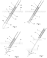
- Figure 4 the system is shown in the assembled state, and Figures 5-9 show the system of Fig. 4 during subsequent implantation steps.
- the distal implant part 1 and the proximal implant part 2 are both arranged inside a sleeve 28 that is guided inside a tube 40.
- the sleeve 28 and the tube 40 are shown transparent so that the elements inside are visible.
- the tube has an inner diameter of about 1.2 mm and an outer diameter of 1.5 mm.
- the sleeve 28 in addition to the distal and proximal implant parts also contains the chord 3 that runs from the distal implant part 1 through the openings 22, 23 and forms a loop proximally of the proximal implant part.
- the system comprises an anchor carrier 51.
- the anchor carrier reaches from proximally of the proximal implant part 2 to distally of the proximal implant part. It forms a seat for the proximal implant part, defines its orientation in the sleeve 28 and secures the proximal implant part against escaping to distal directions.
- it comprises a foot piece 55 forming a proximally-facing shoulder 57 (see Fig. 9 ) against which the distal end of the proximal implant part 2 rests.
- the foot piece comprises a channel 56 (see Fig. 9 ) for the chord, i.e. it is open towards one side to release the chord 3 when the proximal implant part is released.
- the anchor carrier forms a shaft portion 54 ( Fig. 9 ).
- the shaft portion is, in the assembled state, arranged next to the proximal implant part 2, i.e. the proximal implant part 2 and the shaft portion 54 together fit in the cross section of the sleeve 28 that fits into a cross section of the tube 40.
- the tube 40 in the depicted embodiment has a distal tip 41 and is thereby shaped as a cannulated needle.
- the system comprises a pushing mechanism for moving the anchor carrier and the implant parts relative to the sleeve and the tube at least into distal directions (this includes the possibility of retracting the sleeve and/or the tube into a proximal direction while holding the parts still with respect to the tissue).
- Such a pushing mechanism may comprise a pusher 52 that has some flexibility to bending movements but will be capable of transmitting axial forces.
- a pusher 52 may optionally be one-piece with the anchor carrier, i.e. the most distal portion of such a pusher may be the anchor carrier.
- the anchor carrier may be the appropriately shaped distal end of a flexible tube as described hereinbelow referring to Figure 13 .
- the pushing mechanism may alternatively be constituted by a separate piece proximally of the anchor carrier; then optionally the anchor carrier may be fastened to the pusher so that anchor carrier may be retracted into the tube by pulling the pusher after the proximal implant part has been released.
- the needle formed by the tube 40 pierces (if the tube is not piercing, then an separate means or the distal implant part may be used for piercing) the leaflet and then is advanced through the ventricle and then pierces the tissue of the papillary muscle where the distal anchor is to be anchored.
- the tube 40 may comprise a depth indicating marker that, depending on how surgery is carried out, may be supervised by imaging methods or by visual supervision.
- the tube is illustrated to be inserted so that the distal end reaches into muscle tissue 65, especially of the papillary muscle.
- the tube is retracted while the pushing mechanism holds the implant parts and the anchor carrier still.
- the sleeve 28 in this protects the implant parts and the chord from being damaged by the sharp edge of the needle ( Figure 5 ).
- the sleeve is also retracted until the distal implant part is released from the lumen formed by the sleeve.
- the distal implant part 1 is released, its legs 15 spread outwardly, thereby anchoring the distal implant part in the muscle tissue ( Figure 6 ).
- the tube 40 with the sleeve 28, the anchor carrier and the proximal implant part is further retracted ( Figure 7 ) until the distal end of the tube 40 is proximally of the leaflet 61. Because the chord has its end attached to the distal implant part 1 and is looped through the proximal implant part 2, it will by this be pulled out of the tube 40.
- the arms 25 Upon release of the proximal implant part 2 from the tube, the arms 25 will spread out and form, on the lower side (that prior to the release abuts against the shaft portion 54, a spread abutment surface. Relative movements of the muscle tissue and the leaflet tissue will cause one end of the proximal anchor 2 to come into engagement with leaflet tissue, and pulling forces on the chord 3 will cause the proximal implant part 2 to tilt to align the axis 29 with the leaflet tissue ( Figures 10 and 11 ).
- the hook features 27 ( Fig. 2 ) will prevent the proximal implant part from shifting relative to the tissue thereafter, and after some healing time there will be ingrowth of the proximal implant part.
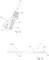
- the method of implanting the implant especially may comprise piercing the leaflet and advancing the tube through the pierced leaflet. If the implantation is carried out by a surgical operation of the open and drained heart, this may be achieved by the surgeon possibly using standard techniques. If alternatively the operation is carried out in a minimally invasive manner, the leaflet hast to be held still for the operation. This may for example be done by a releasable mechanism as illustrated in Figure 12 .
- the illustrated mechanism comprises, attached to an outer tube a main body 101, a swing-out arm 111 with a jaw 112, and a pressing member 80 slideable with respect to the main body 101.
- the leaflet is clamped between the pressing member 80 and the jaw 101.
- the tube 40 is slidable with respect to the pressing member, for example in a central lumen of the pressing member or in a groove defined by the pressing member.
- the jaw comprises a recess for the tube 40.
- Figure 13 yet shows an anchor carrier 51 one-piece with a flexible pusher tube 52.
- a hypotube 50 with a laser- manufactured cut or laser-manufactured cuts 59, for example a helical cut, towards its distal end is provided with a clearance for the proximal implant part.
- the remaining portion of the tube 50, 52 forms the shaft portion 54.
- To form the foot piece 55, at the distal end the tube 50, 52 is left intact except for a narrow axially-running recess that serves as the channel 56.
- hypotube instead of a hypotube of the described kind, also other kinds of suitable tubular elements could be used, for example of a suitable more flexible material (metal, plastic, etc.)
Landscapes
- Health & Medical Sciences (AREA)
- Cardiology (AREA)
- Life Sciences & Earth Sciences (AREA)
- Engineering & Computer Science (AREA)
- General Health & Medical Sciences (AREA)
- Biomedical Technology (AREA)
- Heart & Thoracic Surgery (AREA)
- Veterinary Medicine (AREA)
- Public Health (AREA)
- Animal Behavior & Ethology (AREA)
- Vascular Medicine (AREA)
- Oral & Maxillofacial Surgery (AREA)
- Transplantation (AREA)
- Surgery (AREA)
- Rheumatology (AREA)
- Nuclear Medicine, Radiotherapy & Molecular Imaging (AREA)
- Medical Informatics (AREA)
- Molecular Biology (AREA)
- Prostheses (AREA)
Applications Claiming Priority (2)
| Application Number | Priority Date | Filing Date | Title |
|---|---|---|---|
| CH15342015 | 2015-10-21 | ||
| PCT/CH2016/000137 WO2017066889A1 (en) | 2015-10-21 | 2016-10-19 | Medical apparatus and method for heart valve repair |
Publications (3)
| Publication Number | Publication Date |
|---|---|
| EP3364917A1 EP3364917A1 (en) | 2018-08-29 |
| EP3364917B1 true EP3364917B1 (en) | 2024-11-20 |
| EP3364917C0 EP3364917C0 (en) | 2024-11-20 |
Family
ID=57199848
Family Applications (1)
| Application Number | Title | Priority Date | Filing Date |
|---|---|---|---|
| EP16785326.6A Active EP3364917B1 (en) | 2015-10-21 | 2016-10-19 | Medical apparatus for heart valve repair |
Country Status (5)
| Country | Link |
|---|---|
| US (1) | US10966830B2 (https=) |
| EP (1) | EP3364917B1 (https=) |
| JP (1) | JP6798753B2 (https=) |
| CN (1) | CN108289736B (https=) |
| WO (1) | WO2017066889A1 (https=) |
Families Citing this family (77)
| Publication number | Priority date | Publication date | Assignee | Title |
|---|---|---|---|---|
| WO2006097931A2 (en) | 2005-03-17 | 2006-09-21 | Valtech Cardio, Ltd. | Mitral valve treatment techniques |
| US11259924B2 (en) | 2006-12-05 | 2022-03-01 | Valtech Cardio Ltd. | Implantation of repair devices in the heart |
| US9883943B2 (en) | 2006-12-05 | 2018-02-06 | Valtech Cardio, Ltd. | Implantation of repair devices in the heart |
| US11660190B2 (en) | 2007-03-13 | 2023-05-30 | Edwards Lifesciences Corporation | Tissue anchors, systems and methods, and devices |
| US8382829B1 (en) | 2008-03-10 | 2013-02-26 | Mitralign, Inc. | Method to reduce mitral regurgitation by cinching the commissure of the mitral valve |
| US8715342B2 (en) | 2009-05-07 | 2014-05-06 | Valtech Cardio, Ltd. | Annuloplasty ring with intra-ring anchoring |
| EP3848002A1 (en) | 2008-12-22 | 2021-07-14 | Valtech Cardio, Ltd. | Adjustable annuloplasty devices and adjustment mechanisms therefor |
| US8545553B2 (en) | 2009-05-04 | 2013-10-01 | Valtech Cardio, Ltd. | Over-wire rotation tool |
| US10517719B2 (en) | 2008-12-22 | 2019-12-31 | Valtech Cardio, Ltd. | Implantation of repair devices in the heart |
| US8241351B2 (en) | 2008-12-22 | 2012-08-14 | Valtech Cardio, Ltd. | Adjustable partial annuloplasty ring and mechanism therefor |
| US8353956B2 (en) | 2009-02-17 | 2013-01-15 | Valtech Cardio, Ltd. | Actively-engageable movement-restriction mechanism for use with an annuloplasty structure |
| US9968452B2 (en) | 2009-05-04 | 2018-05-15 | Valtech Cardio, Ltd. | Annuloplasty ring delivery cathethers |
| US12485010B2 (en) | 2009-05-07 | 2025-12-02 | Edwards Lifesciences Innovation (Israel) Ltd. | Multiple anchor delivery tool |
| US10098737B2 (en) | 2009-10-29 | 2018-10-16 | Valtech Cardio, Ltd. | Tissue anchor for annuloplasty device |
| US9180007B2 (en) | 2009-10-29 | 2015-11-10 | Valtech Cardio, Ltd. | Apparatus and method for guide-wire based advancement of an adjustable implant |
| US8734467B2 (en) | 2009-12-02 | 2014-05-27 | Valtech Cardio, Ltd. | Delivery tool for implantation of spool assembly coupled to a helical anchor |
| US10792152B2 (en) | 2011-06-23 | 2020-10-06 | Valtech Cardio, Ltd. | Closed band for percutaneous annuloplasty |
| EP2723274B1 (en) | 2011-06-23 | 2017-12-27 | Valtech Cardio, Ltd. | Closure element for use with annuloplasty structure |
| US8858623B2 (en) | 2011-11-04 | 2014-10-14 | Valtech Cardio, Ltd. | Implant having multiple rotational assemblies |
| EP3970627B1 (en) | 2011-11-08 | 2023-12-20 | Edwards Lifesciences Innovation (Israel) Ltd. | Controlled steering functionality for implant-delivery tool |
| CN104203157B (zh) | 2011-12-12 | 2016-02-03 | 戴维·阿隆 | 心脏瓣膜修补器械 |
| CA2885354A1 (en) | 2012-09-29 | 2014-04-03 | Mitralign, Inc. | Plication lock delivery system and method of use thereof |
| WO2014064694A2 (en) | 2012-10-23 | 2014-05-01 | Valtech Cardio, Ltd. | Controlled steering functionality for implant-delivery tool |
| US10376266B2 (en) | 2012-10-23 | 2019-08-13 | Valtech Cardio, Ltd. | Percutaneous tissue anchor techniques |
| WO2014087402A1 (en) | 2012-12-06 | 2014-06-12 | Valtech Cardio, Ltd. | Techniques for guide-wire based advancement of a tool |
| EP2961351B1 (en) | 2013-02-26 | 2018-11-28 | Mitralign, Inc. | Devices for percutaneous tricuspid valve repair |
| US10449333B2 (en) | 2013-03-14 | 2019-10-22 | Valtech Cardio, Ltd. | Guidewire feeder |
| WO2014152503A1 (en) | 2013-03-15 | 2014-09-25 | Mitralign, Inc. | Translation catheters, systems, and methods of use thereof |
| US10070857B2 (en) | 2013-08-31 | 2018-09-11 | Mitralign, Inc. | Devices and methods for locating and implanting tissue anchors at mitral valve commissure |
| US10299793B2 (en) | 2013-10-23 | 2019-05-28 | Valtech Cardio, Ltd. | Anchor magazine |
| US9610162B2 (en) | 2013-12-26 | 2017-04-04 | Valtech Cardio, Ltd. | Implantation of flexible implant |
| GB2536538B (en) | 2014-09-17 | 2018-07-18 | Cardiomech As | Anchor for implantation in body tissue |
| EP3206629B1 (en) | 2014-10-14 | 2021-07-14 | Valtech Cardio, Ltd. | Apparatus for heart valve leaflet restraining |
| US20160256269A1 (en) | 2015-03-05 | 2016-09-08 | Mitralign, Inc. | Devices for treating paravalvular leakage and methods use thereof |
| EP3288496B1 (en) | 2015-04-30 | 2024-05-29 | Edwards Lifesciences Innovation (Israel) Ltd. | Annuloplasty technologies |
| US20190000624A1 (en) * | 2015-11-02 | 2019-01-03 | Peter Wilson | Distal anchor apparatus and methods for mitral valve repair |
| CN121796784A (zh) | 2015-12-30 | 2026-04-07 | 管道医疗技术股份有限公司 | 二尖瓣瓣叶拴系 |
| WO2017117370A2 (en) | 2015-12-30 | 2017-07-06 | Mitralign, Inc. | System and method for reducing tricuspid regurgitation |
| CA3020407A1 (en) * | 2016-04-11 | 2017-10-19 | Biomet Sports Medicine, Llc | Repair device and method for deploying anchors |
| US10624743B2 (en) | 2016-04-22 | 2020-04-21 | Edwards Lifesciences Corporation | Beating-heart mitral valve chordae replacement |
| US10702274B2 (en) | 2016-05-26 | 2020-07-07 | Edwards Lifesciences Corporation | Method and system for closing left atrial appendage |
| GB201611910D0 (en) | 2016-07-08 | 2016-08-24 | Valtech Cardio Ltd | Adjustable annuloplasty device with alternating peaks and troughs |
| US10357361B2 (en) | 2016-09-15 | 2019-07-23 | Edwards Lifesciences Corporation | Heart valve pinch devices and delivery systems |
| US10925731B2 (en) | 2016-12-30 | 2021-02-23 | Pipeline Medical Technologies, Inc. | Method and apparatus for transvascular implantation of neo chordae tendinae |
| US11696828B2 (en) | 2016-12-30 | 2023-07-11 | Pipeline Medical Technologies, Inc. | Method and apparatus for mitral valve chord repair |
| US11083580B2 (en) | 2016-12-30 | 2021-08-10 | Pipeline Medical Technologies, Inc. | Method of securing a leaflet anchor to a mitral valve leaflet |
| US12472062B2 (en) | 2016-12-30 | 2025-11-18 | Pipeline Medical Technologies, Inc. | Method and apparatus for mitral valve chord repair |
| US9877833B1 (en) | 2016-12-30 | 2018-01-30 | Pipeline Medical Technologies, Inc. | Method and apparatus for transvascular implantation of neo chordae tendinae |
| US11045627B2 (en) | 2017-04-18 | 2021-06-29 | Edwards Lifesciences Corporation | Catheter system with linear actuation control mechanism |
| US10835221B2 (en) | 2017-11-02 | 2020-11-17 | Valtech Cardio, Ltd. | Implant-cinching devices and systems |
| US11135062B2 (en) | 2017-11-20 | 2021-10-05 | Valtech Cardio Ltd. | Cinching of dilated heart muscle |
| US11376127B2 (en) * | 2017-12-20 | 2022-07-05 | W. L. Gore & Associates, Inc. | Artificial chordae tendineae repair devices and delivery thereof |
| CN111655200B (zh) | 2018-01-24 | 2023-07-14 | 爱德华兹生命科学创新(以色列)有限公司 | 瓣环成形术结构的收缩 |
| WO2019145941A1 (en) | 2018-01-26 | 2019-08-01 | Valtech Cardio, Ltd. | Techniques for facilitating heart valve tethering and chord replacement |
| JP7387731B2 (ja) | 2018-07-12 | 2023-11-28 | エドワーズ ライフサイエンシーズ イノベーション (イスラエル) リミテッド | 弁輪形成システムおよびそのための係止ツール |
| US20220117734A1 (en) * | 2018-11-29 | 2022-04-21 | Cardiomech As | Device for Heart Repair |
| US20200188115A1 (en) * | 2018-12-13 | 2020-06-18 | Medtronic Vascular, Inc. | Heart valve repair tool and techniques |
| CN113543727B (zh) | 2019-02-12 | 2024-11-01 | 爱德华兹生命科学公司 | 受控的组织锚定件间隔 |
| WO2020187944A1 (en) | 2019-03-19 | 2020-09-24 | Coremedic Gmbh | Instrument for repairing an atrioventricular heart valve |
| AU2020284630A1 (en) | 2019-05-29 | 2021-11-18 | Edwards Lifesciences Innovation (Israel) Ltd. | Tissue anchor handling systems and methods |
| US12502167B2 (en) | 2019-07-16 | 2025-12-23 | Edwards Lifesciences Corporation | Tissue remodeling systems and methods |
| WO2021014440A2 (en) | 2019-07-23 | 2021-01-28 | Valtech Cardio, Ltd. | Contraction of an annuloplasty structure |
| US12364606B2 (en) | 2019-07-23 | 2025-07-22 | Edwards Lifesciences Innovation (Israel) Ltd. | Fluoroscopic visualization of heart valve anatomy |
| CN114258313A (zh) | 2019-08-28 | 2022-03-29 | 瓦尔泰克卡迪欧有限公司 | 低剖面可转向导管 |
| JP2022546160A (ja) | 2019-08-30 | 2022-11-04 | エドワーズ ライフサイエンシーズ イノベーション (イスラエル) リミテッド | アンカーチャネル先端 |
| KR20220066398A (ko) | 2019-09-25 | 2022-05-24 | 카디악 임플란츠 엘엘씨 | 심장 판막 고리 감소 시스템 |
| WO2021084407A1 (en) | 2019-10-29 | 2021-05-06 | Valtech Cardio, Ltd. | Annuloplasty and tissue anchor technologies |
| WO2021178635A1 (en) * | 2020-03-05 | 2021-09-10 | Apollo Endosurgery Us, Inc. | Surgical fastener deployment system |
| EP4096529B1 (en) | 2020-03-23 | 2025-05-07 | Edwards Lifesciences Innovation (Israel) Ltd. | Self-locking winch |
| CA3178711A1 (en) | 2020-04-22 | 2021-10-28 | Edwards Lifesciences Corporation | Controlled suture tensioning |
| WO2021236634A2 (en) | 2020-05-20 | 2021-11-25 | Cardiac Implants, Llc | Reducing the diameter of a cardiac valve annulus with independent control over each of the anchors that are launched into the annulus |
| JP7701390B2 (ja) | 2020-06-17 | 2025-07-01 | パイプライン メディカル テクノロジーズ, インコーポレイテッド | 僧帽弁腱索修復のための方法及び装置 |
| CA3182316A1 (en) | 2020-06-19 | 2021-12-23 | Edwards Lifesciences Innovation (Israel) Ltd. | Self-stopping tissue anchors |
| WO2022055923A1 (en) | 2020-09-10 | 2022-03-17 | Edwards Lifesciences Corporation | Closing tissue openings |
| US12458498B2 (en) | 2021-02-10 | 2025-11-04 | Edwards Lifesciences Corporation | Implanting grafts to valve leaflets for cardiac procedures |
| JP2025517689A (ja) * | 2022-05-12 | 2025-06-10 | エドワーズ ライフサイエンシーズ イノベーション (イスラエル) リミテッド | 弁の弁尖の治療技術 |
| US12502170B2 (en) | 2022-06-23 | 2025-12-23 | Edwards Lifesciences Corporation | Trigger-based tissue anchor deployment |
Family Cites Families (14)
| Publication number | Priority date | Publication date | Assignee | Title |
|---|---|---|---|---|
| AU5924099A (en) * | 1998-12-31 | 2000-07-24 | Jeffrey E. Yeung | Tissue fastening devices and delivery means |
| US7316706B2 (en) * | 2003-06-20 | 2008-01-08 | Medtronic Vascular, Inc. | Tensioning device, system, and method for treating mitral valve regurgitation |
| WO2011034973A2 (en) * | 2005-02-07 | 2011-03-24 | Abbott Vascular | Methods, systems and devices for cardiac valve repair |
| WO2009081396A2 (en) * | 2007-12-20 | 2009-07-02 | Mor Research Applications Ltd. | Methods and devices for treatment of a heart |
| WO2010070649A1 (en) * | 2008-12-21 | 2010-06-24 | Mor Research Applications Ltd. | Elongated body for deployment in a coronary sinus |
| US20110011917A1 (en) * | 2008-12-31 | 2011-01-20 | Hansen Medical, Inc. | Methods, devices, and kits for treating valve prolapse |
| US9180007B2 (en) * | 2009-10-29 | 2015-11-10 | Valtech Cardio, Ltd. | Apparatus and method for guide-wire based advancement of an adjustable implant |
| SE535140C2 (sv) * | 2010-03-25 | 2012-04-24 | Jan Otto Solem | En implanterbar anordning, kit och system för förbättring av hjärtfunktionen, innefattande medel för generering av longitudinell rörelse av mitralisklaffen |
| WO2012040865A1 (en) | 2010-10-01 | 2012-04-05 | Alberto Weber | Medical apparatus and method for heart valve repair |
| US8454656B2 (en) * | 2011-03-01 | 2013-06-04 | Medtronic Ventor Technologies Ltd. | Self-suturing anchors |
| US9232995B2 (en) * | 2013-01-08 | 2016-01-12 | Medtronic, Inc. | Valve prosthesis and method for delivery |
| US9848880B2 (en) | 2013-11-20 | 2017-12-26 | James E. Coleman | Adjustable heart valve implant |
| US20150250590A1 (en) * | 2014-03-10 | 2015-09-10 | St. Jude Medical, Cardiology Division, Inc. | Transapical mitral chordae replacement |
| GB2536538B (en) * | 2014-09-17 | 2018-07-18 | Cardiomech As | Anchor for implantation in body tissue |
-
2016
- 2016-10-19 WO PCT/CH2016/000137 patent/WO2017066889A1/en not_active Ceased
- 2016-10-19 CN CN201680061791.6A patent/CN108289736B/zh active Active
- 2016-10-19 JP JP2018518518A patent/JP6798753B2/ja active Active
- 2016-10-19 EP EP16785326.6A patent/EP3364917B1/en active Active
- 2016-10-19 US US15/768,884 patent/US10966830B2/en active Active
Also Published As
| Publication number | Publication date |
|---|---|
| EP3364917A1 (en) | 2018-08-29 |
| US10966830B2 (en) | 2021-04-06 |
| EP3364917C0 (en) | 2024-11-20 |
| CN108289736A (zh) | 2018-07-17 |
| US20190175346A1 (en) | 2019-06-13 |
| JP2018531093A (ja) | 2018-10-25 |
| WO2017066889A1 (en) | 2017-04-27 |
| JP6798753B2 (ja) | 2020-12-09 |
| CN108289736B (zh) | 2020-10-16 |
Similar Documents
| Publication | Publication Date | Title |
|---|---|---|
| EP3364917B1 (en) | Medical apparatus for heart valve repair | |
| US12213882B2 (en) | Medical implant and method for heart valve repair | |
| EP3364884B1 (en) | Medical instrument for heart valve repair | |
| JP2018531093A6 (ja) | 心臓弁修復用の医療器具および方法 | |
| JP2018531092A6 (ja) | 心臓弁の修復用の医療インプラントおよび方法 | |
| CN121129502A (zh) | 用于二尖瓣腱索修复的方法和装置 | |
| IL286409B1 (en) | Atrioventricular heart valve repair device | |
| JP2025507909A (ja) | 心臓修復のための軟組織アンカーシステム |
Legal Events
| Date | Code | Title | Description |
|---|---|---|---|
| STAA | Information on the status of an ep patent application or granted ep patent |
Free format text: STATUS: UNKNOWN |
|
| STAA | Information on the status of an ep patent application or granted ep patent |
Free format text: STATUS: THE INTERNATIONAL PUBLICATION HAS BEEN MADE |
|
| PUAI | Public reference made under article 153(3) epc to a published international application that has entered the european phase |
Free format text: ORIGINAL CODE: 0009012 |
|
| STAA | Information on the status of an ep patent application or granted ep patent |
Free format text: STATUS: REQUEST FOR EXAMINATION WAS MADE |
|
| 17P | Request for examination filed |
Effective date: 20180418 |
|
| AK | Designated contracting states |
Kind code of ref document: A1 Designated state(s): AL AT BE BG CH CY CZ DE DK EE ES FI FR GB GR HR HU IE IS IT LI LT LU LV MC MK MT NL NO PL PT RO RS SE SI SK SM TR |
|
| AX | Request for extension of the european patent |
Extension state: BA ME |
|
| DAV | Request for validation of the european patent (deleted) | ||
| DAX | Request for extension of the european patent (deleted) | ||
| RAP3 | Party data changed (applicant data changed or rights of an application transferred) |
Owner name: COREMEDIC AG |
|
| STAA | Information on the status of an ep patent application or granted ep patent |
Free format text: STATUS: EXAMINATION IS IN PROGRESS |
|
| 17Q | First examination report despatched |
Effective date: 20211028 |
|
| GRAP | Despatch of communication of intention to grant a patent |
Free format text: ORIGINAL CODE: EPIDOSNIGR1 |
|
| STAA | Information on the status of an ep patent application or granted ep patent |
Free format text: STATUS: GRANT OF PATENT IS INTENDED |
|
| INTG | Intention to grant announced |
Effective date: 20240621 |
|
| GRAS | Grant fee paid |
Free format text: ORIGINAL CODE: EPIDOSNIGR3 |
|
| GRAA | (expected) grant |
Free format text: ORIGINAL CODE: 0009210 |
|
| STAA | Information on the status of an ep patent application or granted ep patent |
Free format text: STATUS: THE PATENT HAS BEEN GRANTED |
|
| AK | Designated contracting states |
Kind code of ref document: B1 Designated state(s): AL AT BE BG CH CY CZ DE DK EE ES FI FR GB GR HR HU IE IS IT LI LT LU LV MC MK MT NL NO PL PT RO RS SE SI SK SM TR |
|
| REG | Reference to a national code |
Ref country code: GB Ref legal event code: FG4D |
|
| REG | Reference to a national code |
Ref country code: CH Ref legal event code: EP |
|
| REG | Reference to a national code |
Ref country code: DE Ref legal event code: R096 Ref document number: 602016090316 Country of ref document: DE |
|
| REG | Reference to a national code |
Ref country code: IE Ref legal event code: FG4D |
|
| U01 | Request for unitary effect filed |
Effective date: 20241218 |
|
| U07 | Unitary effect registered |
Designated state(s): AT BE BG DE DK EE FI FR IT LT LU LV MT NL PT RO SE SI Effective date: 20250107 |
|
| PG25 | Lapsed in a contracting state [announced via postgrant information from national office to epo] |
Ref country code: IS Free format text: LAPSE BECAUSE OF FAILURE TO SUBMIT A TRANSLATION OF THE DESCRIPTION OR TO PAY THE FEE WITHIN THE PRESCRIBED TIME-LIMIT Effective date: 20250320 Ref country code: HR Free format text: LAPSE BECAUSE OF FAILURE TO SUBMIT A TRANSLATION OF THE DESCRIPTION OR TO PAY THE FEE WITHIN THE PRESCRIBED TIME-LIMIT Effective date: 20241120 |
|
| PG25 | Lapsed in a contracting state [announced via postgrant information from national office to epo] |
Ref country code: ES Free format text: LAPSE BECAUSE OF FAILURE TO SUBMIT A TRANSLATION OF THE DESCRIPTION OR TO PAY THE FEE WITHIN THE PRESCRIBED TIME-LIMIT Effective date: 20241120 |
|
| PG25 | Lapsed in a contracting state [announced via postgrant information from national office to epo] |
Ref country code: NO Free format text: LAPSE BECAUSE OF FAILURE TO SUBMIT A TRANSLATION OF THE DESCRIPTION OR TO PAY THE FEE WITHIN THE PRESCRIBED TIME-LIMIT Effective date: 20250220 |
|
| PG25 | Lapsed in a contracting state [announced via postgrant information from national office to epo] |
Ref country code: GR Free format text: LAPSE BECAUSE OF FAILURE TO SUBMIT A TRANSLATION OF THE DESCRIPTION OR TO PAY THE FEE WITHIN THE PRESCRIBED TIME-LIMIT Effective date: 20250221 |
|
| PG25 | Lapsed in a contracting state [announced via postgrant information from national office to epo] |
Ref country code: PL Free format text: LAPSE BECAUSE OF FAILURE TO SUBMIT A TRANSLATION OF THE DESCRIPTION OR TO PAY THE FEE WITHIN THE PRESCRIBED TIME-LIMIT Effective date: 20241120 |
|
| PG25 | Lapsed in a contracting state [announced via postgrant information from national office to epo] |
Ref country code: RS Free format text: LAPSE BECAUSE OF FAILURE TO SUBMIT A TRANSLATION OF THE DESCRIPTION OR TO PAY THE FEE WITHIN THE PRESCRIBED TIME-LIMIT Effective date: 20250220 |
|
| PG25 | Lapsed in a contracting state [announced via postgrant information from national office to epo] |
Ref country code: SM Free format text: LAPSE BECAUSE OF FAILURE TO SUBMIT A TRANSLATION OF THE DESCRIPTION OR TO PAY THE FEE WITHIN THE PRESCRIBED TIME-LIMIT Effective date: 20241120 |
|
| PG25 | Lapsed in a contracting state [announced via postgrant information from national office to epo] |
Ref country code: SK Free format text: LAPSE BECAUSE OF FAILURE TO SUBMIT A TRANSLATION OF THE DESCRIPTION OR TO PAY THE FEE WITHIN THE PRESCRIBED TIME-LIMIT Effective date: 20241120 |
|
| PG25 | Lapsed in a contracting state [announced via postgrant information from national office to epo] |
Ref country code: CZ Free format text: LAPSE BECAUSE OF FAILURE TO SUBMIT A TRANSLATION OF THE DESCRIPTION OR TO PAY THE FEE WITHIN THE PRESCRIBED TIME-LIMIT Effective date: 20241120 |
|
| PLBE | No opposition filed within time limit |
Free format text: ORIGINAL CODE: 0009261 |
|
| STAA | Information on the status of an ep patent application or granted ep patent |
Free format text: STATUS: NO OPPOSITION FILED WITHIN TIME LIMIT |
|
| 26N | No opposition filed |
Effective date: 20250821 |
|
| REG | Reference to a national code |
Ref country code: CH Ref legal event code: U11 Free format text: ST27 STATUS EVENT CODE: U-0-0-U10-U11 (AS PROVIDED BY THE NATIONAL OFFICE) Effective date: 20251101 |
|
| U20 | Renewal fee for the european patent with unitary effect paid |
Year of fee payment: 10 Effective date: 20250930 |
|
| PGFP | Annual fee paid to national office [announced via postgrant information from national office to epo] |
Ref country code: GB Payment date: 20251022 Year of fee payment: 10 |
|
| PGFP | Annual fee paid to national office [announced via postgrant information from national office to epo] |
Ref country code: CH Payment date: 20251101 Year of fee payment: 10 |
|
| PGFP | Annual fee paid to national office [announced via postgrant information from national office to epo] |
Ref country code: IE Payment date: 20251024 Year of fee payment: 10 |