EP3364159B1 - Computer-implemented method for unitary synthesis and design of flow meters and of compound gauging structures - Google Patents
Computer-implemented method for unitary synthesis and design of flow meters and of compound gauging structures Download PDFInfo
- Publication number
- EP3364159B1 EP3364159B1 EP18020055.2A EP18020055A EP3364159B1 EP 3364159 B1 EP3364159 B1 EP 3364159B1 EP 18020055 A EP18020055 A EP 18020055A EP 3364159 B1 EP3364159 B1 EP 3364159B1
- Authority
- EP
- European Patent Office
- Prior art keywords
- gauging
- compound
- structural
- flowmeter
- design
- Prior art date
- Legal status (The legal status is an assumption and is not a legal conclusion. Google has not performed a legal analysis and makes no representation as to the accuracy of the status listed.)
- Active
Links
- 150000001875 compounds Chemical class 0.000 title claims description 104
- 238000013461 design Methods 0.000 title claims description 59
- 230000015572 biosynthetic process Effects 0.000 title claims description 30
- 238000003786 synthesis reaction Methods 0.000 title claims description 30
- 238000000034 method Methods 0.000 title claims description 29
- 239000000243 solution Substances 0.000 claims description 115
- 230000014509 gene expression Effects 0.000 claims description 32
- 230000000875 corresponding effect Effects 0.000 claims description 31
- 230000004044 response Effects 0.000 claims description 30
- 238000012545 processing Methods 0.000 claims description 12
- 239000012530 fluid Substances 0.000 claims description 7
- 238000010200 validation analysis Methods 0.000 claims description 7
- 238000012512 characterization method Methods 0.000 claims description 6
- 238000003780 insertion Methods 0.000 claims description 6
- 230000037431 insertion Effects 0.000 claims description 6
- 239000003637 basic solution Substances 0.000 claims description 5
- 230000005540 biological transmission Effects 0.000 claims description 5
- 230000002596 correlated effect Effects 0.000 claims description 5
- 238000011835 investigation Methods 0.000 claims description 5
- 230000001427 coherent effect Effects 0.000 claims description 4
- 238000004590 computer program Methods 0.000 claims description 3
- 230000008878 coupling Effects 0.000 claims description 3
- 238000010168 coupling process Methods 0.000 claims description 3
- 238000005859 coupling reaction Methods 0.000 claims description 3
- 230000002194 synthesizing effect Effects 0.000 claims description 3
- 230000003750 conditioning effect Effects 0.000 claims description 2
- 238000010586 diagram Methods 0.000 claims 3
- 239000007788 liquid Substances 0.000 description 11
- 238000006073 displacement reaction Methods 0.000 description 8
- 238000009877 rendering Methods 0.000 description 7
- 238000009795 derivation Methods 0.000 description 6
- 230000003068 static effect Effects 0.000 description 6
- 238000004458 analytical method Methods 0.000 description 5
- 238000011161 development Methods 0.000 description 5
- 230000018109 developmental process Effects 0.000 description 5
- 238000005259 measurement Methods 0.000 description 5
- 238000011144 upstream manufacturing Methods 0.000 description 5
- 238000013459 approach Methods 0.000 description 4
- 239000002585 base Substances 0.000 description 4
- 230000009897 systematic effect Effects 0.000 description 4
- 238000004422 calculation algorithm Methods 0.000 description 2
- 238000004364 calculation method Methods 0.000 description 2
- 230000001419 dependent effect Effects 0.000 description 2
- 239000011159 matrix material Substances 0.000 description 2
- 230000010355 oscillation Effects 0.000 description 2
- 230000008569 process Effects 0.000 description 2
- 239000000126 substance Substances 0.000 description 2
- 238000012795 verification Methods 0.000 description 2
- 230000001133 acceleration Effects 0.000 description 1
- 238000010276 construction Methods 0.000 description 1
- 231100001261 hazardous Toxicity 0.000 description 1
- 230000000977 initiatory effect Effects 0.000 description 1
- 230000005923 long-lasting effect Effects 0.000 description 1
- 238000012986 modification Methods 0.000 description 1
- 230000004048 modification Effects 0.000 description 1
- 230000003287 optical effect Effects 0.000 description 1
- 230000010363 phase shift Effects 0.000 description 1
- 230000000750 progressive effect Effects 0.000 description 1
- 238000012958 reprocessing Methods 0.000 description 1
- 238000000926 separation method Methods 0.000 description 1
- 238000004513 sizing Methods 0.000 description 1
- 238000012360 testing method Methods 0.000 description 1
- XLYOFNOQVPJJNP-UHFFFAOYSA-N water Substances O XLYOFNOQVPJJNP-UHFFFAOYSA-N 0.000 description 1
Images
Classifications
-
- G—PHYSICS
- G01—MEASURING; TESTING
- G01F—MEASURING VOLUME, VOLUME FLOW, MASS FLOW OR LIQUID LEVEL; METERING BY VOLUME
- G01F1/00—Measuring the volume flow or mass flow of fluid or fluent solid material wherein the fluid passes through a meter in a continuous flow
Definitions
- This invention relates to a computer implemented method for unitary synthesis and design of flowmeters and of the compound gauging structures, considered also as combinations of flowmeters, which can be used to design any type of flowmeter or of any compound gauging structures that can be logically imagined in the future to measure flow, based on any working principle known and applicable to any type of industrial environment.
- N. Manohar ('Flowmeter Selection and Sizing', 02/11/2013, www.slideshare.net ) and R. A. Furness (Flow Meas. Instrum., Vol 2 Oct 1991, pages 233-242 ) discusses the selection of a flowmeter for given specified criteria using a classification of flowmeters.
- H. M. Motit (Automatizari si Instrumentatie 5-6/2011 ) discusses the concept of unitary synthesis & classification that provides a systematic way to structure flow metering.
- the method according to this invention is based on the knowledge and the definition of unitary fundamental analytical and structural bases, specific to flow measurement, and initially ensures the storing, separately for flowmeters, and respectively for the compound gauging structures, of a specific "unitary reference logical network ", comprising the basic elements of their unitary bases, namely the basic structural schemes, the unique set of criteria expressed as synthesis logical questions to be followed, the sequence of their approach, the possible related responses, as well as logical restrictions imposed in the correlating of the response solutions, as elements already checked before developing the method, valid for all currently available flowmeters and compound gauging structures.
- the method After the introduction and validation of the set of initial data for configuration and design of the structure of a new type of flowmeter or compound gauging structures, the method provides, related to them, for the successive scrutiny of the set of synthesis criteria and the successive selection of response solutions related to them, the basic constructive configuration of the new type of flowmeter or compound gauging structures being achieved by successively connection, by corresponding correlations, of those responses that are logically compatible each other.
- the method is directly computer implementable and allows both making new types that respond both to the logical coherence of the synthesis of functional blocks of flowmeters, and to the analysis of any type of existing flowmeter or compound gauging structures.
- the structural scheme S1 of the conventional flowmeters consists of a primary element EP and a secondary element ES, the primary element composed in its turn by a reference block BR which functionally provides the constant of the reference parameter X R against variation of the measured flow rate Q, and a sensitive block BS detecting the variation of the parameter X V and thus the variation of the flow rate Q.
- the reference parameter X R is kept constant against the variation in the flow rate Q by the functioning way of the block BR itself, parameter X V being variable according to the variation of the flow rate Q, and the characteristic parameter-X C is the output of the EP element, and the input to the element ES whose output parameter Q R , the rendering parameter of the measured flow rate Q, expressed at the output of the secondary element ES.
- the structural scheme S2a relating to the mono insertion flowmeters is based on an monoinsertion system SI of the sensitive block BS, in addition to the structural scheme S1, and the element EP INSERTION represents the configuration of related primary element.
- Structural scheme S2b of the multipoint insertion flowmeters shown in Figure 3 puts in evidence an index i of the m annulus (rings) in which is imaginary divided the total area A of the measuring section, and also marks the structural blocks and related parameters for each annulus in part, respectively an index j of the n circular segments in which is imaginary divided, in its turn, each annulus (ring), this index marking also structural blocks and related parameters of each circular segment in part.
- EP 1,1 ... EP m, n represent some individual primary elements, each EP i,j having the same structure and same parameters corresponding to those indicated for element EP insert in the structural scheme S2a and corresponding to one of the circular segment of the total area A and a set of primary individual elements SEP.
- the flowmeters with auxiliary fluid comprise a set of primary elements SEP, made by a main primary element EP main , a supplementary primary element EP auxiliary , between the two elements being characteristic placed a variable fluidic resistance RFV.
- the flowmeter of this type reveals an auxiliary fluid flow q, a main characteristic parameter X Cp and an additional characteristic parameter X CS .
- the structure of the by pass type flowmeters(with closed derivation) with the generating (q) by a differential static pressure highlights a set of primary elements SEP made up by a main primary element EP and a supplementary primary element EP bypass .
- the structure of the by-pass flowmeters (with closed derivation), with generating (q) by a dynamic pressure according to structural scheme S6b of Figure 7 , highlights a set of primary elements SEP consisting of a main primary element EP main and an additional primary element EP bypass .
- the structure of the secondary element of flowmeter, scheme S-ES - of Figure 8 comprises a processing block of the output parameter of the primary part of flowmeter of BP-X C , respectively characteristic parameter X C and a transmission block BT - Q R of the parameter Q R , rendering the flow rate measured by the flowmeter, X T representing the parameter transmitted resulting after processing of the characteristic parameter X C of the block BP - X C .
- the structural scheme of the compound gauging structures CD 1 represented in Figure 9 comprises some individual flowmeters D 1 ... D n , components of the compound gauging structure and an Adder-a structural block, specific to any type of compound gauging structure, which provides the calculation of the parameter Q R , rendering the total measured flow rate Q and highlights some partial flows Q 1 .. Q n measured by flowmeters D 1 ... D n .
- the characteristic-parameter X Cj are the level of the free liquid surface upstream of the measuring section, flowmeters, which use modular range flow and respectively the values pair of free liquid surface levels, pair upstream / downstream of the Measuring section for flowmeters which use non-modular flow range.
- Structural scheme of the compound gauging structure type CD 2 shown in Figure 10 is composed of individual gauging structures D 1 ... D m components of the compound gauging structure that have a Sensitive block BS related to the compound gauging structure, common to all individual gauging structures D 1 .. D m of the compound gauging structure, and an Adder of measured partial flow rates Q 1 ...Q m , which ensures at its output the parameter Q R , respectively the rendering of the total measured flow rate Q.
- the Sensitive block BS detects the variation of the passing areas (A 1 ... A m ) of the liquid flow depending on the partial flow rates Q 1 ...
- the liquid level is measured upstream of the measuring sections achieved constructively by each structural reference block BR 1 ... BR m of the individual flowmeters D 1 ... D m in part, these blocks constructively achieving the measuring sections of the liquid flow rate, related to these individual gauging structures.
- the structural scheme of the compound gauging structure type CD 3 represented in Figure 11 is made up by a compound gauging structure type CD 1 and a compound gauging structure type CD 2 , connected in parallel, and an Adder which ensures the calculation of the total measured flow rate Q, and its rendering by the parameter Q R , by the summing up some parameters Q R1 ....Q Rn , by the summing up some parameters Q R1 ...Q Rn+m , which render some measured partial flows rates Q 1 ....Q n+m .
- some individual gauging structures D 1 ... D n are components of the structural scheme related to the compound gauging structure type CD 1
- D n+1 ... D n+m represent some individual gauging structures, components of the structural scheme related to the compound gauging structure type CD 2 .
- type CD 3 is only theoretically possible in principle, by proposing parallel coupling of a compound gauging structure of type CD 1 , with a compound gauging structure of type CD 2 under conditions in which gauging structures D 1 ... D n associated with the compound gauging structure type CD 1 are flowmeters for closed conduits.
- gauging structures D 1 ... D n associated with the compound gauging structure type CD 1 are flowmeters for closed conduits.
- practically it is difficult to make this variant because it is necessary to ensure the continuity of the total flow measuring range, which includes both the low values of the flow measuring ranges of flowmeters for closed conduits, and also the high values of the flow measuring ranges corresponding to flowmeters for open channels.
- the method provides the logical generation of appropriately coded response solutions for a set of 14 criteria for flowmeters, respectively 17 criteria, for compound gauging structures, grouped in 5 "criteria groups" of a constructive-functional nature that can define in a complete manner the construction and operation of any type of conventional or unconventional flowmeter, or any compound gauging structures.
- criteria groups are:
- the method of unitary synthesis and design of any type of flowmeter is based on the following of a procedural sequence of several processing stages, each stage assuming browsing of algorithm able steps which proves the essence of the computer program that implements the present method.
- the first stage envisages creating and storing of the unitary logical reference network, for configuring a new basic type of flowmeter, network made up of:
- Second defining stage of method involves entry and validation of the "set of initial configuration data" of a new basic type of flowmeter.
- the third stage involves establishing, for the flowmeter to be configured, the mode of analytical expression of the measuring flow rate and the structural group embodying its structural ensemble
- a first step it is checked whether can be validated the "set of input data" as usable for starting configuration and design of a new basic type of flowmeter, and in negative case being modified those input data which do not allow selection of logically consistent solutions among those indicated in Table 2, as possible in this respect, according to the criteria no. 1, 2, 3.
- the flowmeter has the overall structural scheme of a conventional type, it is used the "conventional structure" according to the solution related to the criterion no. 4 of Table no. 2, respectively structural scheme S1 shown in Figure 1 .
- the fourth stage is intended to configure the primary part of the flowmeter, for both conventional flowmeters and unconventional flowmeters.
- This stage provides in a first sub-stage the setting up of the structural type for configuration of the primary part of the flowmeter.
- the fourth stage then proceeds with the design of the primary part of the flowmeter, provided by a primary element EP (for flowmeters with “conventional structure”) respectively a set of primary elements SEP (for flowmeters with “unconventional structure”) set made by connections between two or more EP or between one or more EP with “conventional structure” from Figure 1 coupled with an auxiliary device (insertion system, fluidic resistance) according to the followed variant of "unconventional structure”.
- a primary element EP for flowmeters with "conventional structure
- SEP for flowmeters with "unconventional structure”
- Step 3-DC After modifying the constructive solution initially chosen for BR, and then reprocessing the steps 3-DC ... 10-DC.
- Step 5 If the result of the new verification is positive, proceed to Stage 5, and if it is negative, return to Step 7- DC, after modifying the constructive solution initially chosen for BS, and then reprocess steps 7- DC ... 10-DC.
- step 5 If in the end the test result is positive, go to Stage 5, and if negative go back to step 2-DN and reprocess steps 7-DC ....9-DC, then proceed to step 3-DN (if required by the specification from step 2-DN) and then with steps 4-DN and 5-DN, after changing the constructive solution initially chosen for BS to one or more EPs in the SEP. If the result of the check is finally positive, go to Stage 5, if not, go back to step 7-DC related to step 2-DN, repeating the same cycle, until an affirmative response is obtained, following the verification in step 5-DN.
- Stage 5 involves the configuration of the secondary part - the secondary element ES - of the flowmeter, which in turn has as a first sub- stage the configuration of overall structural scheme of ES, a second sub-stage the unitary constructive design of the processing block BP - and then a third sub- stage, the unitary constructive design of the transmission block BT-Qp.
- Step 3 takes place the achievement of BP- , according to that basic solution corresponding to criterion no.13 of Table 2, which corresponds to the analysis from the previous step, using a constructive variant correlated with the structural scheme of the flowmeter assembly shown in Table 6.
- step 4 of the stage it is constructively achieved the transmission block BT-Qp, by choosing a solution among those related to criterion no. 14 of Table 2.
- Stage 6 envisages the achievement of the structural assembly of the new type of flowmeter configured, by connecting the constructive solutions obtained in the previous steps, and involves firstly, the editing of the overall detailed constructive structural scheme finalized for the new basic type of the flowmeter configured, and finally setting the name of the new basic type of flowmeter, depending on the constructive solution used for the design of the primary part thereof.
- the method for unitary synthesis and design of compound gauging structures involves, in a similar manner with that used for individual flowmeters, conducting several procedural working stages, where each stage suppose proceeding of algorithm based procedural steps which constitutes the essence of the computer program which implements the said method.
- Said network is built up of:
- the first three groups of criteria mentioned above include, with reference to the flowmeters composing the compound gauging structure, the 14 criteria (questions) and the corresponding response solutions previously indicated, that ensure the unitary synthesis and design of the flowmeters.
- the second stage involves input and validation of the "set of initial configuration data" of a new basic type of compound gauging structure, whereby after, it is checked if the inputted "initial data for configuration and design", are the minimum needed, by responding to the provisions of criteria 1, 2, 3.1, 3.2 of Table 7, and in the negative case being necessary to complete the "set of initial configuration data", with the missing data, against the previsions of criteria 1,2, 3.1,3.2 of Table 7.
- the third stage provides the setting for the component gauging structures of the future compound gauging structure, of the analytical mode of expression of flow rate and of the type of the structure.
- a first sub-stage it is established, on the one hand the analytical mode of expression of the measured flow rate and on the other hand, the type of structural group as " conventional structure” or “unconventional structure”, chosen to be within the structural schemes of the component gauging structure of the compound gauging structure to be set up.
- the component gauging structures of the compound gauging structure must have the structural scheme of the conventional type and the selection of the component gauging structures is, among those which have a "conventional structure" according to the solution code 4.1 .1 related to criterion no. 4.1 of Table 7, respectively Schematic scheme S1 from Figure1 .
- the component gauging structures of the compound gauging structure must accordingly be "conventional flowmeters”.
- the component gauging structures of the compound gauging structure have a structural scheme of unconventional type, and the selection of the component gauging structures, is made among those having the structure in accordance with, those of variants of "unconventional structural scheme"S2a, S2b, S4, S5, or S6b corresponding to solution or solutions previously chosen for analytical expression of flow rate within the solution group code 3.1.2 of Table 7.
- the fifth stage consists in validating the novelty of the configured compound gauging structure, verifying that the configured compound gauging structure is among those achieved so far and shown in Table 8, and in the negative case it is proceeded to the editing of the detailed constructive scheme for the new basic type of set up compound gauging structure and the denomination of the new type of compound gauging structure.
- the component gauging structures found in existing combinations are replaced with other gauging structures, among those already pre-selected as appropriate, by browsing the previous stages. The cycle is repeated until it is not found the compound gauging structure as set up in Table 8.
Landscapes
- Physics & Mathematics (AREA)
- Fluid Mechanics (AREA)
- General Physics & Mathematics (AREA)
- Measuring Volume Flow (AREA)
Description
- This invention relates to a computer implemented method for unitary synthesis and design of flowmeters and of the compound gauging structures, considered also as combinations of flowmeters, which can be used to design any type of flowmeter or of any compound gauging structures that can be logically imagined in the future to measure flow, based on any working principle known and applicable to any type of industrial environment.
- Are known in practice methods of synthesizing and configuration of flowmeters and of the compound gauging structures, which are based on investigation of various areas of physics, and following a possible identification of the developments in physics, finalized by a new working principle or law, potentially usable for measuring one of the parameters which are involved in the analytical relationships of flow rate definition, and consequently in the flow measurement.
- In the case of a successful investigation, these methods are based on the possible achievement of a new type of flowmeter, that uses said identified physical principle, and thus being only an approaching mode and not a method.
- Disadvantage of this type of methods is that they have effectively a limited practical efficiency, due to the fact that they depend fully of the hazardous evolution of the development of physics, and thus they do not have their own, systematic, methodological basis for the synthesis of flowmeters and of the compound gauging structures. Under these circumstances, the state of the art essentially relies not on unitary methods of analysis and synthesis, but in fact only on approaching modes. Consequently, they are subject to random and intuitive criteria, and implicitly require a complex, laborious, long lasting and very costly effort of investigation and synthesis / configuration of the flowmeters, respectively of the compound gauging structures.
- On the other hand, these types of approaches are becoming more and more inefficient, due to the progressive increase of the necessary investigative effort, the growing demand for permanent diversification, by specialization, of the fields of physics and their accelerated development.
- N. Manohar ('Flowmeter Selection and Sizing', 02/11/2013, www.slideshare.net) and R. A. Furness (Flow Meas. Instrum., Vol 2 Oct 1991, pages 233-242) discusses the selection of a flowmeter for given specified criteria using a classification of flowmeters.
- H. M. Motit (Automatizari si Instrumentatie 5-6/2011) discusses the concept of unitary synthesis & classification that provides a systematic way to structure flow metering.
- The scope of the invention is defined by the claims.
- Technical problem solved by this invention lies in systematic, predictable and logical coherent use of the unitary fundamental analytical and structural bases, specific to flow measurement in the elaboration and the defining of a unitary method for synthesis and design of the flowmeter and of the compound gauging structures, allowing its computer based implementation. This method thus enables the unitary design of any basic type of flowmeter or of compound gauging structures logically achieveable in the future,making thus possible to replace the current approach on the configuration / synthesis of flowmeters and of the compound gauging structures, which is fully and permanently dependent of and awaiting the development of the various fields of physics that they are investigating based on intuitive and random criteria.
- The method according to this invention is based on the knowledge and the definition of unitary fundamental analytical and structural bases, specific to flow measurement, and initially ensures the storing, separately for flowmeters, and respectively for the compound gauging structures, of a specific "unitary reference logical network ", comprising the basic elements of their unitary bases, namely the basic structural schemes, the unique set of criteria expressed as synthesis logical questions to be followed, the sequence of their approach, the possible related responses, as well as logical restrictions imposed in the correlating of the response solutions, as elements already checked before developing the method, valid for all currently available flowmeters and compound gauging structures.
- After the introduction and validation of the set of initial data for configuration and design of the structure of a new type of flowmeter or compound gauging structures, the method provides, related to them, for the successive scrutiny of the set of synthesis criteria and the successive selection of response solutions related to them, the basic constructive configuration of the new type of flowmeter or compound gauging structures being achieved by successively connection, by corresponding correlations, of those responses that are logically compatible each other.
- The method is directly computer implementable and allows both making new types that respond both to the logical coherence of the synthesis of functional blocks of flowmeters, and to the analysis of any type of existing flowmeter or compound gauging structures.
- The computer implemented method for unitary synthesis and design of flowmeters and of compound gauging structures, according to the invention, offers the following advantages:
- can be unitary implemented, independently of the development of various fields of physics, for all flowmeters and compound gauging structures, by knowing and applying the unitary analytical and structural bases, identified to be common to all flowmeters.
- it ensures the unitary approach of the configuration and design of flowmeters and compound gauging structures, respectively;
- due to its direct computer based implementation, it drastically reduces the effort, the time and the cost of configuration and design of the flowmeters and the compound of gauging structures, respectively.
- it ensures, through its application, the acceleration of the imagining and the achievement, on predictable and systematic basis, of new types of flowmeters and flowmeter combinations, which have not been achieved so far.
- In the following, it is given an example on the implementation of the unitary method for synthesis and design of flowmeters and respectively of compound gauging structures, in relation with
Figures 1, 2, 3, 4 ,5, 6, 7, 8 ,9, 10 ,11 , wherein: -
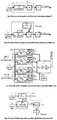
Fig.1 Structure of conventional flowmeters - structural scheme S1; -
Fig.2 Structure of monoinsertion flowmeters - structural scheme S2a; -
Fig.3 Structure of multinsertion flowmeters - structural scheme S2b; -
Fig.4 Structure of flowmeters with auxiliary fluid - structural scheme S4; -
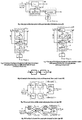
Fig.5 Structure of flowmeters with open derivation- structural scheme S5; -
Fig.6 Structure of by pass flowmeters (closed derivation) with generation (q) by a differential static pressures - structural scheme S6a; -
Fig.7 Structure of by pass flowmeters (closed derivation) with generation (q) by a dynamic pressure - structural scheme S6b; -
Fig. 8 Structure of the secondary element of flowmeter- scheme S-ES ; -
Fig.9 Structural scheme of compound gauging structures-type CD1; -
Fig.10 Structural scheme of compound gauging structures- type CD; -
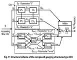
Fig.11 Structural scheme of compound gauging structures type CD3; - As shown in
Figure 1 , the structural scheme S1 of the conventional flowmeters, consists of a primary element EP and a secondary element ES, the primary element composed in its turn by a reference block BR which functionally provides the constant of the reference parameter XR against variation of the measured flow rate Q, and a sensitive block BS detecting the variation of the parameter XV and thus the variation of the flow rate Q. - The reference parameter XR is kept constant against the variation in the flow rate Q by the functioning way of the block BR itself, parameter XV being variable according to the variation of the flow rate Q, and the characteristic parameter-XC is the output of the EP element, and the input to the element ES whose output parameter QR, the rendering parameter of the measured flow rate Q, expressed at the output of the secondary element ES.
- As shown in
Figure 2 , the structural scheme S2a relating to the mono insertion flowmeters, is based on an monoinsertion system SI of the sensitive block BS, in addition to the structural scheme S1, and the element EP INSERTION represents the configuration of related primary element. - Structural scheme S2b of the multipoint insertion flowmeters shown in
Figure 3 , puts in evidence an index i of the m annulus (rings) in which is imaginary divided the total area A of the measuring section, and also marks the structural blocks and related parameters for each annulus in part, respectively an index j of the n circular segments in which is imaginary divided, in its turn, each annulus (ring), this index marking also structural blocks and related parameters of each circular segment in part. - EP1,1 ... EPm, n represent some individual primary elements, each EPi,j having the same structure and same parameters corresponding to those indicated for element EPinsert in the structural scheme S2a and corresponding to one of the circular segment of the total area A and a set of primary individual elements SEP.
- The flowmeters with auxiliary fluid according to the structural scheme S4, shown in
Figure 4 , comprise a set of primary elements SEP, made by a main primary element EPmain, a supplementary primary element EPauxiliary, between the two elements being characteristic placed a variable fluidic resistance RFV. - The flowmeter of this type reveals an auxiliary fluid flow q, a main characteristic parameter XCp and an additional characteristic parameter XCS.
- In the structure of the flowmeter with open derivation according to the structural scheme S5, shown in
Figure 5 , is a set of primary elements SEP consisting of a supplementary primary element EPopen derivation which communicates with an element EPmain by a variable fluidic resistance RFV. Within the, XCp = Δps (Q) represents a main characteristic parameter, being made by the differential static pressures Δps which depends on the flow Q. Formally Δps depends on (Q-q) but since Q is much larger than q, it is practically considered that Δps depends directly on Q. - The structure of the by pass type flowmeters(with closed derivation) with the generating (q) by a differential static pressure, according to the structural scheme S6a of
Figure 6 , highlights a set of primary elements SEP made up by a main primary element EP and a supplementary primary element EPbypass. The intervening parameters have the significance of XCp = Δps(Q) - a main characteristic parameter, achieved by the differential static pressure Δps which, for the same reasons as indicated in the structural scheme S5, depends directly on the flow Q and on an additional characteristic parameter XCs. - The structure of the by-pass flowmeters (with closed derivation), with generating (q) by a dynamic pressure according to structural scheme S6b of
Figure 7 , highlights a set of primary elements SEP consisting of a main primary element EPmain and an additional primary element EPbypass. The intervening parameters are, a main characteristic parameter XCp = pD (Q), achieved by a dynamic pressure pD which formally depends on the difference (Q-q) but since q is very small compared to Q, it is practically assumed that pD depends on Q, and respectively an additional characteristic parameter XCs, - The structure of the secondary element of flowmeter, scheme S-ES - of
Figure 8 , comprises a processing block of the output parameter of the primary part of flowmeter of BP-XC, respectively characteristic parameter XC and a transmission block BT - QR of the parameter QR, rendering the flow rate measured by the flowmeter, XT representing the parameter transmitted resulting after processing of the characteristic parameter XC of the block BP - XC. - The structural scheme of the compound gauging structures CD1 represented in
Figure 9 comprises some individual flowmeters D1 ... Dn, components of the compound gauging structure and an Adder-a structural block, specific to any type of compound gauging structure, which provides the calculation of the parameter QR, rendering the total measured flow rate Q and highlights some partial flows Q1 .. Qn measured by flowmeters D1 ... Dn. For the variants of compound gauging structures comprising flowmeters for open channels, the characteristic-parameter XCj are the level of the free liquid surface upstream of the measuring section, flowmeters, which use modular range flow and respectively the values pair of free liquid surface levels, pair upstream / downstream of the Measuring section for flowmeters which use non-modular flow range. - Structural scheme of the compound gauging structure type CD2 shown in
Figure 10 is composed of individual gauging structures D1 ... Dm components of the compound gauging structure that have a Sensitive block BS related to the compound gauging structure, common to all individual gauging structures D1 .. Dm of the compound gauging structure, and an Adder of measured partial flow rates Q1 ...Qm, which ensures at its output the parameter QR, respectively the rendering of the total measured flow rate Q. The Sensitive block BS detects the variation of the passing areas (A1 ... Am) of the liquid flow depending on the partial flow rates Q1 ... Qm, and converts them into variation of the level L of the free liquid surface in the upstream measuring section. The scheme highlights some partial flow rates Q1 ... Qm measured by flowmeters D1 ... Dm and respectively a unique characteristic parameter XC = L, structurally common to all individual gauging structures, belonging to the compound gauging structure, where L is the level of free surfaces of the measured liquid, common to all measuring sections of the partial flow rates Q1 ... Qm The liquid level is measured upstream of the measuring sections achieved constructively by each structural reference block BR1 ... BRm of the individual flowmeters D1 ... Dm in part, these blocks constructively achieving the measuring sections of the liquid flow rate, related to these individual gauging structures. - The structural scheme of the compound gauging structure type CD3 represented in
Figure 11 is made up by a compound gauging structure type CD1 and a compound gauging structure type CD2, connected in parallel, and an Adder which ensures the calculation of the total measured flow rate Q, and its rendering by the parameter QR, by the summing up some parameters QR1....QRn, by the summing up some parameters QR1...QRn+m, which render some measured partial flows rates Q1....Qn+m. Thus, some individual gauging structures D1 ... Dn are components of the structural scheme related to the compound gauging structure type CD1, and Dn+1 ... Dn+m represent some individual gauging structures, components of the structural scheme related to the compound gauging structure type CD2. - It should be noted that a combination of type CD3 is only theoretically possible in principle, by proposing parallel coupling of a compound gauging structure of type CD1, with a compound gauging structure of type CD2 under conditions in which gauging structures D1 ... Dn associated with the compound gauging structure type CD1 are flowmeters for closed conduits. However, practically it is difficult to make this variant because it is necessary to ensure the continuity of the total flow measuring range, which includes both the low values of the flow measuring ranges of flowmeters for closed conduits, and also the high values of the flow measuring ranges corresponding to flowmeters for open channels.
- The method provides the logical generation of appropriately coded response solutions for a set of 14 criteria for flowmeters, respectively 17 criteria, for compound gauging structures, grouped in 5 "criteria groups" of a constructive-functional nature that can define in a complete manner the construction and operation of any type of conventional or unconventional flowmeter, or any compound gauging structures. Thus, for flowmeters, the five groups of criteria are:
- I- use destination of flowmeters;
- II- basic analytical mode of expression of the measured flow rate;
- III- overall flowmeter structure;
- IV- configuration of the primary part of the flowmeter;
- V configuration of the secondary part of the flowmeter.
- As mentioned above, for flowmeters 14 analytical / synthesis criteria are defined as follows:
- 1. type of way that measured fluid flows;
- 2. type of the measured flow (Q);
- 3. basic analytical expression of the measured flow rate;
It is considered that all analytical relations of the "Conventional Expressing (Measuring) of Q Flow Rate" use the generic relationship: Q = XR · XV where:- XR = Reference parameter= Functionally constant, against to the variation in time of the measured flow rate (Q)
- XV = Variable parameter depending on Q;
- a) XR has the variants: Vconstant; mconstant; τ constant
- b) XV has, depending on its corresponding variant of XR, variants τ-1 variable; Vvariable; mvariable;
- a) XR has the variants: Aconstant; Vconstant
- b) XV has, depending on its corresponding variant XR, the variants: vvariable ; Avariable
- a) Depending on the "Variable parameter" (XV = speed/ local speeds measured in the SM section), with constant maintaining of the "Reference parameter" (XR = A=ASM = area-of the measuring section).
- b) Depending on the secondary flow, dependent on the main flow Q
- 4. Overall structural schemes of the flowmeter which solves (materializes) the "response solutions" related to Criterion no. 3 ;
- 5 Overall structural scheme of the primary part of flowmeter;
- 6.Configuring the BR block ;
- 7Functional position of (BR) related to flowmeter body ;
- 8 Relative functional position between parts of (BR) ;
- 9 Output parameter of (BR) = Variable parameter (XV) It is considered that for all structural variants of flowmeters:
XV = Output parameter of (BR) Ξ Input parameter in (BS), and the (XV) solutions have the variants depending on the type of (BR); - 10. Participation of (BR) in achieving of (BS) ;
- 11. Output parameter of (BS) = Characteristic parameter(XC) ;
It is taken into consideration that for all structural variants of flowmeters:
XC = Output of (BS) Ξ Output parameter of (EP)
The solutions for the characteristic parameter (XC) rendered by its usual physical expressions depend on the Variable parameter (XV) which, obtained at the output of (BR), depends in its turn on the type of (BR). The solutions of XC are the same for both "conventional flowmeters" and "unconventional flowmeters" - 12. Detailing criteria of the (BS) configuration ;
- 13. Configuration Module of BP - XC, on processing the input parameter in ES (referred to as "characteristic parameter XC") ;
- 14. Configuration module of the block BT - QR, on the expression of QR, the parameter of the rendering the measured flow rate.
- The method of unitary synthesis and design of any type of flowmeter is based on the following of a procedural sequence of several processing stages, each stage assuming browsing of algorithm able steps which proves the essence of the computer program that implements the present method.
- The first stage envisages creating and storing of the unitary logical reference network, for configuring a new basic type of flowmeter, network made up of:
-
Figures 1 ....7 - Variants of structural schemes of flowmeters -
Figure 8 - Basic structure of the secondary element of flowmeter (Scheme S-ES) - Table 1 - Correlation variants of the reference parameter solutions XR with the variable parameter solutions XV, for the configuration of the flowmeters
- Table 2 - Reference matrix of criteria and related solutions, necessary to be followed for the configuration of the flowmeters
- Table 2A - Usual solutions to achieve the characteristic parameter XC, related to criterion 11 of Table 2 (correlated with solutions for BR and XV)
- Table 3 - Logical incompatible sequences, which need to be avoided between certain solutions responding to Criteria no. 2.1 and 3 from Table 2
- Table 4 - Logically incompatible sequences that need to be avoided between certain solutions, responding to Criteria 2.1 and no. 6.2 from Table 2
- Table 5 - Logical incompatible sequences, to be avoided between certain synthesis solutions related to Criteria no. 6.2, 7, 8 from Table 2
- Table 6 - Necessary correlations between constructive solutions for configuration and the design of the secondary element ES, and the overall structural schemes of the flowmeters
- Second defining stage of method, involves entry and validation of the "set of initial configuration data" of a new basic type of flowmeter.
- Within it, it is entered the "set of initial configuration and structural design data" of a new basic type of flowmeter, checking if the configuration and design data initially entered are the minimum necessary, responding to the criteria no.1,2,3 of Table 2.
- In case of missing data, the "set of initial data" will be completed with missing data, according to the criteria no.1, 2, 3 of Table 2.
- The third stage involves establishing, for the flowmeter to be configured, the mode of analytical expression of the measuring flow rate and the structural group embodying its structural ensemble
- In a first step, it is checked whether can be validated the "set of input data" as usable for starting configuration and design of a new basic type of flowmeter, and in negative case being modified those input data which do not allow selection of logically consistent solutions among those indicated in Table 2, as possible in this respect, according to the criteria no. 1, 2, 3.
- With the view to establish the mode of analytical expression of the measuring flow rate, it is performed the sequential selection among the solutions related to criteria no. 1, 2, 3 of Table 2 and Table 3 of those which, using the "initial configuration and design data", perform the complete and coherent characterization of the mode of analytical expression of the measuring flow rate, which must be ensured by the configuration and design of the new basic type of flowmeter
- In the third stage, it proceeds to the setting up of the structural group in which will be embodied the overall structural scheme of the flowmeter.
- It is thus analyzed in which of the structural group it will be embodied the new flowmeter to be configured, according to the analytical expression of the flow rate, set out previously.
- If the flowmeter has the overall structural scheme of a conventional type, it is used the "conventional structure" according to the solution related to the criterion no. 4 of Table no. 2, respectively structural scheme S1 shown in
Figure 1 . - Otherwise, it is used a "unconventional structure" belonging to the group of structures related to criterion no. 4 of Table 2, selecting one of the structural schemes S2Aa, S2b, S4, S5, S6a, S6b shown in
Figures 2 ..7 . - The fourth stage is intended to configure the primary part of the flowmeter, for both conventional flowmeters and unconventional flowmeters.
- This stage provides in a first sub-stage the setting up of the structural type for configuration of the primary part of the flowmeter.
- The fourth stage then proceeds with the design of the primary part of the flowmeter, provided by a primary element EP (for flowmeters with "conventional structure") respectively a set of primary elements SEP (for flowmeters with "unconventional structure") set made by connections between two or more EP or between one or more EP with "conventional structure" from
Figure 1 coupled with an auxiliary device (insertion system, fluidic resistance) according to the followed variant of "unconventional structure". - Consequently, this stage is particularly complex and ensures solving of the same objectives, both for the configuration and design of "conventional structure" type flowmeters and those with "unconventional structure", by carrying out procedural steps which, due to the specificity of the two structural types indicated above are grouped as follows:
-
- Step 1- DC - Identification of the primary element EP as the structural mode of achieving of the primary part of the flowmeter, according to the solution corresponding to the sub-criterion no.5.1 of Table 2;
- Step 2-DC - Setting up the overall configuration of the primary element EP, composed by the reference block BR and the sensitive block BS, according to the solution related the sub-criterion no. 5.1 of Table 2 which corresponds to the structural scheme $1 of
Figure 1 ; - Step 3-DC- Setting the actual physical parameter for achievement of the reference parameter Xp among the variants indicated in Table 1 in accordance with the previously established response solutions corresponding to criteria no. 1 and 2 of Table 2;
- Step 4- DC- Setting up the basic solution embodying the reference block BR, from the variants indicated in Table 2, corresponding to criterion no. 6.2, by avoiding the logically incompatible sequences between the solutions, shown in Table 4;
- Step 5-DC - Constructive configuration of the reference block BR by sequentially choosing of the constructive solutions corresponding to criteria no. 7 and 8 of Table 2, and correlating them by avoiding the logically incompatible sequences between solutions, indicated in Table 5;
- Step 6-DC- Setting the actual physical parameter for the achievement of output parameter of the reference block BR (respectively the "variable parameter Xy") among the variants of the response to criterion no. 9 of Table 2, corresponding to the type of BR previously set, solution for Xy being necessary to correlate with the solution set above for Xp, so as to be within the correlating variants indicated in Table 1;
- Step 7 DC - Initiation of the design of BS by choosing of the constructive connecting solution of BR with BS, among the response solutions related Criterion no. 10 of Table 2;
- Step 8 - DC - Setting the actual physical parameter for the achievement of the output parameter from BS (i.e., the "characteristic parameter X,.") starting with the investigation of the response solutions indicated in Table 2A, solutions related to criterion no.11 of Table 2, according to the previously chosen solutions for the constructive type of the block BR and for variant of the parameter X,.
- Step 9 - DC - Define the configuration and design of BS by choosing the appropriate constructional configuration solutions among the responses related to criteria no.11 and 12 of Tables 2 and 2A;
- Step 10 - DC - Check the condition that the solution set for the Primary element EP of the "conventional flowmeter" is new and not be found at the existing flowmeters.
- If the result is positive, go to Stage 5.
- If the result is negative, return to Step 3-DC, after modifying the constructive solution initially chosen for BR, and then reprocessing the steps 3-DC ... 10-DC.
- If the result of the new verification is positive, proceed to Stage 5, and if it is negative, return to Step 7- DC, after modifying the constructive solution initially chosen for BS, and then reprocess steps 7- DC ... 10-DC.
- This cycle is repeated until, after the processing of
Step 10, get an affirmative response, when it is possible to move to Stage 5. -
- Step1-DN- Generic identification of the set of the primary elements SEP as structural mode of achieving the primary part of the flowmeter, namely the selection of its concrete structural configuration, among the variants of the response solutions corresponding to the sub-criterion no.5.2, indicated in Table 2, corresponding to the structural schemes $2a, S2b, $4, S5, S6a, S6b, shown successively in
Figures 2,3,4 ,5,6,7 . - Step 2-DN- Unitary design of each of the primary element EP component of the specific structure previously estab- lished for the set of the primary elements SEP of the unconventional flowmeter to be configured, by processing the same steps 2- DC .. 9- DC, corresponding to the conventional flowmeter configuration.
Then proceed to Step 3-DN (for SEP made in structural variants S2a, S2b, S4, S5, S6b) or directly to Step 4-DN (for SEP made in structural variant S6a). - Step 3-DN - Provides the design of afferent devices related to some of the structural variants of SEP, as follows : insertion system SI (for schemes S2a, S2b, S6b), respectively variable fluidic resistance RFV (for structural schemes $4, $5).
- Step 4-DN - Constructive and informational implementation of the connections between the primary elements EP components of the Set of Primary Elements SEP previously set, following its specific structural scheme, for respective unconventional flowmeter configured.
- Step 5- DN- Check whether the solution configured for the Set of Primary Elements (SEP) of the "unconventional flowmeter" is new and it is not found in the existing flowmeters;
If the result is positive, go to Stage 5. If the result is negative go back to step 2-DN and reprocess steps 3-DC ... 9- DC, then proceed to step 3-DN (if required processing with-by the specification from step 2-DN) and then with the steps 4-DN, 5-DN, after modifying the constructive solution chosen initially for BS, to one or more EP within the SEP. - If in the end the test result is positive, go to Stage 5, and if negative go back to step 2-DN and reprocess steps 7-DC ....9-DC, then proceed to step 3-DN (if required by the specification from step 2-DN) and then with steps 4-DN and 5-DN, after changing the constructive solution initially chosen for BS to one or more EPs in the SEP. If the result of the check is finally positive, go to Stage 5, if not, go back to step 7-DC related to step 2-DN, repeating the same cycle, until an affirmative response is obtained, following the verification in step 5-DN.
- Next, for both conventional flowmeters and unconventional flowmeters, the following stages are proceed suc- cessively:
Stage 5 involves the configuration of the secondary part - the secondary element ES - of the flowmeter, which in turn has as a first sub- stage the configuration of overall structural scheme of ES, a second sub-stage the unitary constructive design of the processing block BP -and then a third sub- stage, the unitary constructive design of the transmission block BT-Qp.
- According to this working stage, in a first step, the constructive configuration of ES is carried out, following the overall structural scheme S-ES shown in
Figure 8 . - In a later step takes place the analysis of, in terms of the configuration of the processing block BP-Xc, of the structural scheme indicated for ES, within the overall structural scheme chosen for the flowmeter at the beginning of its configuration.
- In Step 3 takes place the achievement of BP-, according to that basic solution corresponding to criterion no.13 of Table 2, which corresponds to the analysis from the previous step, using a constructive variant correlated with the structural scheme of the flowmeter assembly shown in Table 6.
- In step 4 of the stage, it is constructively achieved the transmission block BT-Qp, by choosing a solution among those related to criterion no. 14 of Table 2.
- Stage 6, envisages the achievement of the structural assembly of the new type of flowmeter configured, by connecting the constructive solutions obtained in the previous steps, and involves firstly, the editing of the overall detailed constructive structural scheme finalized for the new basic type of the flowmeter configured, and finally setting the name of the new basic type of flowmeter, depending on the constructive solution used for the design of the primary part thereof.
- The method for unitary synthesis and design of compound gauging structures involves, in a similar manner with that used for individual flowmeters, conducting several procedural working stages, where each stage suppose proceeding of algorithm based procedural steps which constitutes the essence of the computer program which implements the said method.
- In a first stage, it is created and stored the "reference unitary logical network", necessary to for configure a new compound gauging structure.
- Said network is built up of:
-
Figures 1 ...7 - Variants of basic structural schemes of flowmeters component of compound gauging structures -
Figures 9 ...11 - Variants of basic structural schemes of compound gauging structures - Table 7 - Reference Matrix of the criteria and of their related solutions required for configuring compound gauging structures
- Table 8 - Main compound gauging structures achieved till now
- For compound gauging structures, the groups of the logical criteria (queries) which sequential browsing ensures either the analysis of existing structures or the synthesis of new combinations, are as follows:
- I- use destination of the flowmeters;
- II- successive characterization of the basic analytical expression of the flow rate measured by the flowmeters, composing the compound gauging structure;
- III- configuration of overall structural schemes;
- IV- characterization of the constructive configuration of the flowmeters composing the compound gauging structure;
- V conditions regarding the constructive configuration of the flowmeters composing the compound gauging structure
- The first three groups of criteria mentioned above include, with reference to the flowmeters composing the compound gauging structure, the 14 criteria (questions) and the corresponding response solutions previously indicated, that ensure the unitary synthesis and design of the flowmeters.
- In addition to these, the specificity of the configuration and structural design of the compound gauging structures, with reference to Table 7, requires additional use of two sub-criteria no.3.2 and 4.2 and of three criteria no.15, 16, 17 as follows:
- Sub-criterion 3.2- Analytical mode of expression of the total flow rate measured by the ensemble of flowmeters composing the compound gauging structure.
- Sub-criterion 4.2- Types of structural schemes of compound gauging structures.
- Criterion 15.- Functional compatibility between flowmeters composing the compound gauging structure.
- Criterion 16.- Full measurement of the flow range required by the combination, within the limits and with the accuracy initially set
- Criterion -providing the rendering of the measured flow rate, according to the solution chosen for the sub-criterion no.3.2
- The second stage involves input and validation of the "set of initial configuration data" of a new basic type of compound gauging structure, whereby after, it is checked if the inputted "initial data for configuration and design", are the minimum needed, by responding to the provisions of
criteria 1, 2, 3.1, 3.2 of Table 7, and in the negative case being necessary to complete the "set of initial configuration data", with the missing data, against the previsions ofcriteria 1,2, 3.1,3.2 of Table 7. - Then it is checked whether one can validate the "set of input data" as used for starting the configuration of a new basic type of compound gauging structure, and in negative case being made modifications to those input data which do not allow selection of solutions logically consistent with data, indicated as possible in this respect in Table 7, according to criteria no. 1,2, 3,1, 3.2.
- The third stage, provides the setting for the component gauging structures of the future compound gauging structure, of the analytical mode of expression of flow rate and of the type of the structure.
- In a first sub-stage it is established, on the one hand the analytical mode of expression of the measured flow rate and on the other hand, the type of structural group as " conventional structure" or "unconventional structure", chosen to be within the structural schemes of the component gauging structure of the compound gauging structure to be set up. In this regard, it is provided the consecutive selection among the solutions related to
Criteria 1, 2, 3.1 of Table 7, of those consistent with the "initial design data" and ensures the complete and coherent characterization of the analytical expression of the flow rate measured in the manner required by these "data", which must be ensured by the gauging structures then chosen as components of the compound gauging structure, for its configuration. - If the solution chosen for the analytical expression of the flow rate is the conventional expression, the component gauging structures of the compound gauging structure, must have the structural scheme of the conventional type and the selection of the component gauging structures is, among those which have a "conventional structure" according to the solution code 4.1 .1 related to criterion no. 4.1 of Table 7, respectively Schematic scheme S1 from
Figure1 . The component gauging structures of the compound gauging structure must accordingly be "conventional flowmeters". In the event that the solution chosen for the analytical expression of the flow rate, is the "unconventional expression", the component gauging structures of the compound gauging structure have a structural scheme of unconventional type, and the selection of the component gauging structures, is made among those having the structure in accordance with, those of variants of "unconventional structural scheme"S2a, S2b, S4, S5, or S6b corresponding to solution or solutions previously chosen for analytical expression of flow rate within the solution group code 3.1.2 of Table 7. - Therefore the component gauging structures must have a structural scheme of unconventional type, being called "unconventional flowmeters"
- The fourth stage defined as Setting up the new compound gauging structure, abbreviated "CD", firstly involves choosing the type of structural scheme to follow in the setting up the compound gauging structure, among solutions CD1, CD2, or CD3 related to criterion no.4.2 of Table 7.
- It is then passed at establishing, among solutions related to sub-criterion no.4.2 of Table 7 of that type of constructive solution to be followed in achieving the compound gauging structure, to be configured which complies with the previous options regarding: the structural type of the component flowmeters (conventional or unconventional), respectively the type of transport line of the fluid to be measured. Then it is set up the compound gauging structure CD by choosing the component gauging structures among those pre-selected preliminary by following the previous stages and ending with their corresponding coupling.
- It is then finalized the setting up of the compound gauging structure by solving the conditionings provided by the criteria no. 15, 16, and 17 of Table 7, by using their related solutions.
- The fifth stage consists in validating the novelty of the configured compound gauging structure, verifying that the configured compound gauging structure is among those achieved so far and shown in Table 8, and in the negative case it is proceeded to the editing of the detailed constructive scheme for the new basic type of set up compound gauging structure and the denomination of the new type of compound gauging structure. In affirmative case, the component gauging structures found in existing combinations are replaced with other gauging structures, among those already pre-selected as appropriate, by browsing the previous stages. The cycle is repeated until it is not found the compound gauging structure as set up in Table 8.
| Mode of expression of the flow rate | Basic solutions for expressing the analytical flow rate | Variants usable for correlating the reference and variable values |
| Direct expression | QV = V/τ | XR = V; XV = τ |
| XR = τ; XV = V | ||
| Qm = m/τ | XR = m; XV = τ | |
| XR = τ; XV = m | ||
| Indirect expression | QV = A · v | XR = A; XV = v |
| XR = v; XV = A | ||
| Qm = A · V · ρ | XR = A; XV = v | |
| XR = v; XV = A |

| Type of BR | Parameter of XR | Usual solutions to achieve the characteristic parameter (XC) |
| Measuring chamber (CM) with discontinuous filling / discharge | τ-1 | Number of electrical pulses |
| V | Liquid level (level of the liquid-gas separation surface) | |
| Bell displacement | ||
| Piston displacement | ||
| m | Output signal of the balance | |
| Measuring chamber (CM) with continuous filling / discharge | τ-1 | Switching frequency of (CM) |
| Rotation frequency of (CM) | ||
| Linear displacement of deformable wall of (CM) | ||
| Linear displacement of no-deformable wall of (CM) - sealed | ||
| Wall oscillation frequency of (CM) | ||
| Wall / Walls rotation frequency of (CM) | ||
| Wall rotating sliding frequency of (CM) | ||
| A | Linear displacement of (SM) | |
| Static pressure drop on the mobile annular orifice plate | ||
| Linear displacement of the mobile component of (SM) | ||
| Angular movement of the mobile component of (SM) | ||
| Free liquid surface level (heat) | ||
| Concentration (injected substance) obtained following the mixing with the liquid which flow rate is measured | ||
| v | Rotation velocity of the mobile part of (SM) | |
| Oscillation frequency of the mobile part of (SM) | ||
| Differential static pressures (Δps) | ||
| Dynamic pressure (pD) | ||
| Force | ||
| Frequency of the swirled jet | ||
| Measuring section (MS) | Electromotive tension | |
| Ionization current | ||
| Concentration (injected substance), obtained after mixing with the liquid which flow is measured | ||
| Magneto-nuclear resonance (MNR) | ||
| Optical parameter | ||
| Ultrasonic parameter | ||
| Rotation Frequency of (SM) | ||
| Curvilinear displacement of (SM) | ||
| Transit time of (SM) | ||
| Angular displacement of rotor | ||
| Thermal parameter | ||
| Phase shift between signals (proportional to deformation of the measuring tube) |
| Note: The solutions suggested for the characteristic parameter XC are the usual ones and are not limitative and can be completed at any time |
| Synthetic criterion (code number) | Response solution with incompatible sequences | ||
| 2.1 | Qaverage | Qaverage | |
| 3 | 3.1 | Flow rate conventionally - indirect expressed | - |
| 3.2 | - | Flow rate unconventionally expressed | |
| Synthesis criteria (code number) | Response solution with incompatible sequences | |||
| 2.1 | Qaverage | Qaverage | Qinstantaneous | Qinstantaneous |
| 6.2 | Solution no.6.2.1.2 (Measuring chamber with quasi-continuous / continuous filling/discharge) | Solution no.6.2.2 (Measuring section) | Solution no. 6.2.1.1 (Measuring chamber with discontinuous filling / discharge) | Solution no.6.2.1.2 (Measuring chamber with quasi-continuous filling / discharge) |
| Synthesis criterion (code number) | Response solutions with Incompatible sequence | ||||
| 6.2 | Measuring chamber (CM) with filling /discharge | Measuring section (SM) | Measuring section (SM) | ||
| with discontinuous filling / discharge | with quasi-continuous filling / discharge | with continuous filling / discharge | |||
| 7 | Immobile (CM) | Mobile (CM) | Immobile (CM) | Immobile (SM) | Mobile (SM) |
| 8 | (CM) without moving parts | (CM) with moving parts | (CM) without moving parts | (SM) with sealed moving parts | (SM) with sealed moving parts |
| Structural code of flowmeter | Response solutions usable in the synthesis of the secondary element (ES) |
| S1 | • Block BP-X C : does not mathematically process the characteristic parameter XC |
| •Block BT-Q R : provides local indication of the flow rate (needle with dial) | |
| Note: The correlation of the above solutions for the two blocks that compose ES (according to | |
| S1, | • Block BP-X C : mathematically processes the characteristic parameter XC |
| S2a, | |
| S2b, | • Block BT-Q R : All solutions shown in Table 2 |
| S4, | |
| S5, | |
| S6a, | |
| S6b. |

| Type of the structural scheme of the CD | Type of way that measured fluid flows | Compound gauging structures (abbreviated "CD") |
| CD1 | Closed conduit | Compound gauging structures of two rotary vane/propeller flowmeters |
| Open channel | Compound gauging structure, operating in non-modular flow range, which comprise: | |
| - triangular - profile weirs | ||
| - flat - V weirs | ||
| Compound gauging structures which comprise underflow gates that use non-modular flow range | ||
| Compound gauging structures, operating in modular flow range: | ||
| 1. Which comprise the following weirs: | ||
| - thin - plate weirs | ||
| - triangular - profile weirs | ||
| - trapezoidal - profile weirs | ||
| - rectangular broad - crested weirs | ||
| - rounded - nose horizontal crested weirs | ||
| - flat - V weirs | ||
| - V - shaped broad - crested weirs | ||
| - streamlined - triangular profile weirs | ||
| 2. Which comprise the following flumes: | ||
| CD2 | Open channel | a. Parshall and SANIIRI |
| b. According to ISO 4359, with: | ||
| - rectangular transverse profile | ||
| - trapezoidal transverse profile | ||
| - "U" transverse profile | ||
| 3. Which comprise a combination between gauging structures specified above at no. 1 and no. 2 | ||
| 4. Which comprise gates | ||
| Note: These compound gauging structures operate only in a modular flow range, that allows a common measurement of the water level (with one single device - namely a sensitive block BS common to all component gauging structures), only upstream of the measuring areas of the component gauging structures, but not downstream of them. |
Claims (6)
- Computer implemented method for unitary synthesis and design of flowmeters and of compound gauging structures, characterized in that in order to achieve any basic type of flowmeter, conventional or unconventional, both among the existing ones, as well as among those logical imaginable and achievable, it comprises browsing the following stages :Stage 1 - Creating and memorizing the unitary reference logic network needed to configure a new type of flowmeter;Stage 2 - Input and validating "set of initial setting up data" of a new basic type of flowmeter;Stage 3 - Establishing, for the flowmeter to be synthesized, of analytical mode of expression of the measuring flow rate and of the structural group in which could be fitted the overall structural scheme of the flowmeter;Stage 4 - Configuration the primary part of the flowmeter, which involves the setting up of the structural type of the primary part of the flowmeter, provided by a primary element EP (for "conventional structure" made up by the reference block BR and the sensitive block BS), respectively, by a set of primary elements SEP, (for "unconventional flowmeters", set made up by the connection between several EP or by the connection between one or two EP and an auxiliary device) and continuing for " conventional flowmeters" with the unitary design of the primary element EP, the setting up of the overall structure of the primary element EP, the unitary constructive design of the Reference Block BR, the unitary constructive design of the Sensitive Block BS and validation of the novelty of the synthesized EP solution, and for "unconventional flowmeters", the setting up of the structural configuration of SEP, the design of the component primary elements EP, the design of the auxiliary devices (for some structural variants), the constructive and informational achievement of the connections between the primary elements EP composing the SEP followed by validating the novelty of the solution of the synthesized SEP;Stage 5 - Configuration of the secondary element ES of the flowmeter, which consists of setting up the overall structural diagram of ES, the unitary constructive design of the processing block BP - XC and respectively the unitary constructive design of the transmission block BT- QR ;Stage 6 - Achieving the structural assembly of the new type of configured flowmeter by connecting the constructive solutions obtained in the previous stages;wherein the implementation of stage 2 involves the following procedural steps:Step 1 - Input of the "set of initial structural configuration and design data" of a new basic type of flowmeter that meets criteria 1, 2, 3 of Table 2 and the provisions of Table 2A;Step 2 : Validate the "input data set" that can be used to start the configuration and the design of a new basic type of flowmeter by filling in the missing data and modifying those input data that do not allow the selection of logically consistent solutions from the other solutions shown in Table 2, as being possible in this respect, according to Criteria no.1, 2, 3;wherein the implementation of stage 3 involves following procedural steps:Step 1 - Consecutive selection among the solutions related to criteria no. 1, 2, 3 of Table 2 of those which, using the "initial configuration and design data", perform the complete and coherent characterization of the analytical mode of expression of the measuring flow rate, which must be ensured by the configuration and the design of the new basic type of flowmeter;Step 2- Setting up the structural group which fits the new flowmeter to be configured, according to the analytical mode of expression of the flow rate set out above, and then in the case of a conventional flowmeter, it is used the conventional structure according to the solution related to criterion no.4 of Table no. 2, respectively the structural scheme S1 shown in Figure 1, and in the case of an unconventional flowmeter it is used the " unconventional structure" belonging to the Group of structures related to criterion no.4 of Table 2, choosing one of the structural schemes S2a, S2b, S4, S5, S6a, S6b shown in Figures 2 ... 7;wherein the implementation of stage 4 involves following the next steps:A. For conventional flowmetersStep 1-DC Identifying the primary element EP as the structural mode of achieving the primary part of the flowmeter, according to the solution related to sub-criterion no.5.1 of Table 2, which corresponds to the structural diagram S1 of Figure 1;Step 2-DC Establishing the overall configuration the primary element EP, made by the reference block BR and the sensitive block BS according to the solution related to sub-criterion no. 5.1 of Table 2 corresponding to the structural diagram S1 of Figure 1;Step 3-DC- Establishing the actual physical parameter to be achieved by the reference parameter XR among the variants indicated in Table 1 in accordance with the previously established response solutions corresponding to criteria no.1 and 2 of Table 2;Step 4 - DC - Establishing the basic solution for achieving the reference block BR among the variants indicated in Table 2, corresponding to sub-criterion no. 6.2, by avoiding the logically incompatible sequences among the solutions shown in Table 4;Step 5-DC - Constructive design of the reference block BR by sequentially establishing the constructive solutions corresponding to criteria no.7 and 8 in Table 2, and correlating them by avoiding the logically incompatible sequences among the solutions shown in Table 5 ;Step 6-DC - Determining the actual physical parameter to be achieved at the output from the reference block BR (namely, the "variable parameter XV") among the response possibilities related to the criterion no.9 of Table 2, corresponding to the type of BR previously set, the solution for XV must be correlated with the solution stated above for XR, so as to be within the correlation variants indicated in Table 1;Step 7- DC- Starting the design of BS by choosing the constructive solution for connecting the BR with the BS, among the response variants related to the criterion 10 in Table 2;Step 8-DC- Setting the actual physical parameter for achieving the output parameter from BS (or the "characteristic parameter XC"), starting with the investigation of the response solutions shown in Table 2A, related to the criterion no.11 of Table 2,corresponding to the previously chosen solutions for the constructive type of block BR and for the variant of XV;Step 9 - DC - Finalizing the configuration and design of BS by choosing among the responses related to criteria no.11 and 12 of Tables 2 and 2A of the corresponding constructive configuration solutions;Step 10 - DC - Verifying that the solution set up for the Primary Element EP of the "conventional flowmeter" is new and does not match the existing flowmeters, and if the result is positive, go to stage 5 and if the result is negative returns to step 3-DC after modifying the constructive solution initially chosen for BR, and resolving steps 3-DC ....10-DC, checking the result, and if the result is positive proceed to stage 5, and if it is negative returns at step 7-DC, after changing the constructive solution initially chosen for BS, and the steps 7- DC ....10-DC, cycle, are proceeded again, the whole procedure is repeated until after the processing of step 10 has been reached an affirmative response, when it is possible to proceed to stage 5;B. For non-conventional flowmeters:Step 1-DN - Generic identification of the set of the primary elements SEP as the structural mode of achieving the primary part of the flowmeter, respectively the selection of its concrete structural configuration, among the variants of the response solutions corresponding to the sub-criterion 5.2, indicated in Table 2, which correspond to the structural schemes S2a, S2b, S4, S5, S6a, S6b shown successively in Figures 2,3,4,5,6,7;Step 2-DN- Unitary design of each of the primary element EP component of the specific structure previously set up for the set of primary elements SEP of the unconventional flowmeter to be configured, by browsing the same steps 2-DC... 9-DC corresponding to the configuration of conventional flowmeters, and is then go to step 3-DN, for SEP achieved in structural variants S2a, S2b, S4, S5, S6b, or directly to step 4-DN, for SEP achieved in structural variant S6a;Step 3-DN - Design of devices related to some of the structural variants of SEP, as follows: the insertion system SI for schemes S2a, S2b, S6b and the variable fluidic resistance RFV, for structural schemes S4, S5;Step 4-DN- Achieving the constructive and informational connections between the primary elements EP, the components of the set of primary elements SEP previously set up, by following its specific structural scheme, for that set up unconventional flowmeter;Step 5- DN- Check whether the solution configured for the set of primary elements SEP of the "unconventional flowmeter" is new and does not match the existing flowmeters, and if the result is positive go to stage 5, and if the result is negative returns to step 2-DN, and steps 3-DC ....9-DC are proceed again, then proceed to step 3-DN, if it is imposed by the prevision of step 2-DN, and then with steps 4-DN, 5-DN after modifying the constructive solution initially chosen for the block BR for the one or more EP of the SEP and check if the final outcome is positive, in which case it proceeds to stage 5, while if it is negative it returns to the step 2-DN, and proceed again steps 7-DC ...9-DC, and then with step 3-DN, if it is imposed by the prevision of step 2-DN, and then with steps 4-DN and 5-DN after modifying the constructive solution initially chosen for BS at one or more EP in the SEP, so that if the result is positive then passes to stage 5, and if not, return to step 7-DC related to step 2-DN, by repeating the same cycle until an affirmative response is obtained, following the condition in step 5-DN;wherein the implementation of stage 5 involves the constructive synthesis of the secondary part of the flowmeter, respectively of the secondary element ES, following the general structural scheme S-ES, shown in Figure 8, by achieving the processing block BP-XC, respectively the transmission block BT-QR, by the choosing of basic solutions among those related to the criteria no.13, 14 of Table 2, which are indicated in Table 6 to be correlated to the overall structural schema of the flowmeter, initially set.
- Computer implemented method for unitary synthesis and design of flowmeters and of compound gauging structures, according to claim 1, characterized in that the implementation of the stage 1 involves the creation and storing of the "unitary reference logic network" needed to achieve the unitary configuration and design of new basic types of flowmeters.
- Computer implemented method for unitary synthesis and design of flowmeters and of compound gauging structures according to claim 1, characterized in that the implementation of Stage 6 involves editing the detailed overall constructive structural scheme, completed for the new basic type of the configured flowmeter and naming of the new basic type of flowmeter, according to the constructive solution used for the unitary configuration and design of its primary part.
- Computer implemented method for unitary synthesis and design of flowmeters of compound gauging structures characterized in that, in order to achieve any compound gauging structure, it comprises browsing the following stages:Stage 1 - Creating and storing the unitary reference logical network, for synthesizing a new compound gauging structure;Stage 2 - Introduction and validation of the "set of initial configuration data "of a new basic type of compound gauging structure;Stage 3 - Establishing, for the gauging structures component of the future compound gauging structure, the analytical mode of expression of the flow rate and of the type of structure which involves, on the one hand, the establishing the analytical mode of expression of the flow rate to be measured and, on the other hand, the setting of the chosen structural type of the structural schemes of the gauging structures component of the compound gauging structure;Stage 4 -Configuration of the new compound gauging structure CD;Stage 5 - Validation of the novelty of the synthesized compound gauging structure;wherein with the purpose of implementing stage 2, it proceeds to the input of the set of initial data for configuration and structural design of a new basic type of compound gauging structure, which must meet criteria no.1, 2, 3 of Table 7, validation of the input data set that is usable for the unitary configuration and design of a new basic type of compound gauging structure, and if it is not validated, modifying those input data which do not allow selection of logically consistent with each other solutions indicated in Table 7, according to the criteria no.1,2,3; wherein with the purpose of implementing stage 3, it proceeds to the next procedural steps:Step 1. The consecutive selection among the solutions related to criteria no. 1, 2, 3.1 of Table 7, of those that fits the "initial configuration and design data" and performs the complete and consistent characterization of the analytical expression of the measured flow rate in the manner required by these " data", which must be ensured by the flowmeters which are then chosen as components of the compound gauging structure, in order to synthesize it;Step 2 - Verify the condition if corresponding to the solution chosen for the analytical expression of the flow rate, the gauging structures of the compound gauging structure have the conventional type of the structural scheme (structure);Step 3 For the case of a conventional type of the structural scheme, are selected the component gauging structures, among those having a "conventional structure" according to the solution corresponding to criterion no. 4 of Table 7, respectively structural scheme S1 of Figure 1, and in the case of a structural scheme of unconventional type, the component gauging structures are selected, among those having the structure according to the "variants of unconventional structural scheme" S2a, S2b, S4, S5, S6a or S6b, within the solution group code 3.1.2 of Table 7, corresponding to the solution previously selected for the analytical expression of flow rate;wherein with the purpose of implementing stage 4, it proceeds to the following procedural steps:Step 1 - Choosing the type of structural scheme to follow in synthesis of the compound gauging structure, among the solutions CD1, CD2, or CD3, related to criterion no.4.2 of Table 7;Step 2 - Establish the solutions related to criterion no. 4.2 of Table 7, of that type of constructive solution to be followed in achieving the CD to be the synthesized, which complies with previous options on: the structural type of the component gauging structures, conventional or unconventional, respectively the type of the way that measured fluid flows;Step 3 - Configuration of the compound gauging structure by choosing the component gauging structures among those preliminary selected, by proceeding the previous stages and finalizing with their corresponding coupling;Step 4 - Completion of the configuration of the compound gauging structures by solving the conditionings provided by criteria no. 15, 16, and 17 of Table 7, and using the indicated related solutions for them;wherein in the view of implementing stage 5, it is checked if the configured compound gauging structure is found within those achieved so far and indicated in Table 8, and if this is the case the component flowmeters which are found in existing compound gauging structures, are replaced with other gauging structures, among the already preliminary selected as being appropriate, through completion of the previous steps.
- Computer implemented method for unitary synthesis and design of flowmeters and of compound gauging structures according to claim 4, characterized in that with the purpose of implementing the stage 1, it proceeds at creating and storing the " Reference unitary logical network " necessary to unitary configuration and design of new basic types of compound gauging structures.
- Computer program product for implementing the unitary method for synthesis and design of the flowmeters according to claim 1 and of the compound gauging structures according to claim 4.
Applications Claiming Priority (1)
| Application Number | Priority Date | Filing Date | Title |
|---|---|---|---|
| ROA201700095A RO132778A2 (en) | 2017-02-20 | 2017-02-20 | Computer-implemented method for unitary configuration and design of flow-meters and flow-meter combinations |
Related Parent Applications (1)
| Application Number | Title | Priority Date | Filing Date |
|---|---|---|---|
| RO201700095 Previously-Filed-Application | 2017-02-20 |
Publications (3)
| Publication Number | Publication Date |
|---|---|
| EP3364159A2 EP3364159A2 (en) | 2018-08-22 |
| EP3364159A3 EP3364159A3 (en) | 2019-01-30 |
| EP3364159B1 true EP3364159B1 (en) | 2020-01-22 |
Family
ID=61557009
Family Applications (1)
| Application Number | Title | Priority Date | Filing Date |
|---|---|---|---|
| EP18020055.2A Active EP3364159B1 (en) | 2017-02-20 | 2018-02-12 | Computer-implemented method for unitary synthesis and design of flow meters and of compound gauging structures |
Country Status (2)
| Country | Link |
|---|---|
| EP (1) | EP3364159B1 (en) |
| RO (1) | RO132778A2 (en) |
Cited By (1)
| Publication number | Priority date | Publication date | Assignee | Title |
|---|---|---|---|---|
| EP4001856A1 (en) | 2020-11-24 | 2022-05-25 | Motit, Horia Mihai | Reaction flow meter without moving parts in individual, by-pass and respectively extended configuration, and a method of measuring the flow based on it |
Families Citing this family (2)
| Publication number | Priority date | Publication date | Assignee | Title |
|---|---|---|---|---|
| CN114739487B (en) * | 2022-02-23 | 2025-04-11 | 上海市燃气设备计量检测中心有限公司 | Anti-interference detection method and system for ultrasonic gas meter |
| EP4471385B1 (en) * | 2023-05-29 | 2025-09-03 | Motit, Horia Mihai | Functional method of linearizing the dependence of the force exerted on the reaction element of a flowmeter with the flow rate, and linear reaction flowmeter configured on the basis of that method |
-
2017
- 2017-02-20 RO ROA201700095A patent/RO132778A2/en unknown
-
2018
- 2018-02-12 EP EP18020055.2A patent/EP3364159B1/en active Active
Non-Patent Citations (1)
| Title |
|---|
| None * |
Cited By (1)
| Publication number | Priority date | Publication date | Assignee | Title |
|---|---|---|---|---|
| EP4001856A1 (en) | 2020-11-24 | 2022-05-25 | Motit, Horia Mihai | Reaction flow meter without moving parts in individual, by-pass and respectively extended configuration, and a method of measuring the flow based on it |
Also Published As
| Publication number | Publication date |
|---|---|
| EP3364159A2 (en) | 2018-08-22 |
| RO132778A2 (en) | 2018-08-30 |
| EP3364159A3 (en) | 2019-01-30 |
Similar Documents
| Publication | Publication Date | Title |
|---|---|---|
| EP3364159B1 (en) | Computer-implemented method for unitary synthesis and design of flow meters and of compound gauging structures | |
| USRE36597E (en) | Apparatus and method for measuring two- or three-phase fluid flow utilizing one or more momentum flow meters and a volumetric flow meter | |
| US3701280A (en) | Method and apparatus for determining the supercompressibility factor of natural gas | |
| US6681189B1 (en) | Method and system for determining flow rates and/or fluid density in single and multiple-phase flows utilizing discharge coefficient relationships | |
| EP2801797A1 (en) | Steam flow metering device and metering method therefor | |
| US3705979A (en) | Method of processing production well logging data | |
| CN107330218A (en) | Axial pin type sensor and its radial load demarcation and computational methods, device and system | |
| CN106225862A (en) | The simple and direct compensation method of gas flow | |
| CN105784707A (en) | Gas-liquid two-phase flow measurement method based on high-speed photography technology and device thereof | |
| CN112284471B (en) | Universal differential pressure gas mass flow measurement method and its transmitter and calculation system | |
| EP2843376A1 (en) | Gas flow meter program of constriction device and flow measurement method and flow measurement device using same | |
| CN109917152A (en) | A kind of mean velocity in vertical measurement method | |
| McKelvey et al. | Turbulent motion, mixing, and kinetics in a chemical reactor configuration | |
| US3232104A (en) | Mass flowmeter | |
| GB2638564A (en) | Virtual flow metering using acoustics | |
| US3266309A (en) | Mass flowmeter | |
| CN101187660A (en) | Double-groove orifice-type mixing metering device | |
| Raghavan | Some theoretical results useful in analyzing well performance under solution-gas drive | |
| Dayev | Theoretical modelling of natural gas unsteady flow rate measurement using variable differential pressure method | |
| Lari et al. | Error correction of a coriolis mass flow meter in two-phase flow measurment using Neuro-Fuzzy | |
| US9441995B2 (en) | System and method for monitoring a bi-phase fluid | |
| CN106323366A (en) | Ray attenuation technique-based gas-liquid two-phase flow measuring method and device | |
| Han et al. | Void fraction measurement method in gas/liquid two-phase stratified flow | |
| KR101522243B1 (en) | a gas mass flow meter program using turbine and the measuring device using thereof | |
| Haldun Ünalmis | Flow measurement optimization using surface measurements and downhole sound speed measurements from local or distributed acoustic sensors |
Legal Events
| Date | Code | Title | Description |
|---|---|---|---|
| PUAI | Public reference made under article 153(3) epc to a published international application that has entered the european phase |
Free format text: ORIGINAL CODE: 0009012 |
|
| STAA | Information on the status of an ep patent application or granted ep patent |
Free format text: STATUS: THE APPLICATION HAS BEEN PUBLISHED |
|
| AK | Designated contracting states |
Kind code of ref document: A2 Designated state(s): AL AT BE BG CH CY CZ DE DK EE ES FI FR GB GR HR HU IE IS IT LI LT LU LV MC MK MT NL NO PL PT RO RS SE SI SK SM TR |
|
| AX | Request for extension of the european patent |
Extension state: BA ME |
|
| PUAL | Search report despatched |
Free format text: ORIGINAL CODE: 0009013 |
|
| AK | Designated contracting states |
Kind code of ref document: A3 Designated state(s): AL AT BE BG CH CY CZ DE DK EE ES FI FR GB GR HR HU IE IS IT LI LT LU LV MC MK MT NL NO PL PT RO RS SE SI SK SM TR |
|
| AX | Request for extension of the european patent |
Extension state: BA ME |
|
| RIC1 | Information provided on ipc code assigned before grant |
Ipc: G01F 1/00 20060101AFI20181221BHEP |
|
| STAA | Information on the status of an ep patent application or granted ep patent |
Free format text: STATUS: REQUEST FOR EXAMINATION WAS MADE |
|
| 17P | Request for examination filed |
Effective date: 20190219 |
|
| RBV | Designated contracting states (corrected) |
Designated state(s): AL AT BE BG CH CY CZ DE DK EE ES FI FR GB GR HR HU IE IS IT LI LT LU LV MC MK MT NL NO PL PT RO RS SE SI SK SM TR |
|
| GRAP | Despatch of communication of intention to grant a patent |
Free format text: ORIGINAL CODE: EPIDOSNIGR1 |
|
| STAA | Information on the status of an ep patent application or granted ep patent |
Free format text: STATUS: GRANT OF PATENT IS INTENDED |
|
| INTG | Intention to grant announced |
Effective date: 20190711 |
|
| RIN1 | Information on inventor provided before grant (corrected) |
Inventor name: MOTIT HORIA MIHAI |
|
| GRAS | Grant fee paid |
Free format text: ORIGINAL CODE: EPIDOSNIGR3 |
|
| GRAJ | Information related to disapproval of communication of intention to grant by the applicant or resumption of examination proceedings by the epo deleted |
Free format text: ORIGINAL CODE: EPIDOSDIGR1 |
|
| GRAL | Information related to payment of fee for publishing/printing deleted |
Free format text: ORIGINAL CODE: EPIDOSDIGR3 |
|
| GRAJ | Information related to disapproval of communication of intention to grant by the applicant or resumption of examination proceedings by the epo deleted |
Free format text: ORIGINAL CODE: EPIDOSDIGR1 |
|
| GRAL | Information related to payment of fee for publishing/printing deleted |
Free format text: ORIGINAL CODE: EPIDOSDIGR3 |
|
| STAA | Information on the status of an ep patent application or granted ep patent |
Free format text: STATUS: REQUEST FOR EXAMINATION WAS MADE |
|
| INTG | Intention to grant announced |
Effective date: 20190711 |
|
| INTC | Intention to grant announced (deleted) | ||
| GRAP | Despatch of communication of intention to grant a patent |
Free format text: ORIGINAL CODE: EPIDOSNIGR1 |
|
| STAA | Information on the status of an ep patent application or granted ep patent |
Free format text: STATUS: GRANT OF PATENT IS INTENDED |
|
| INTG | Intention to grant announced |
Effective date: 20191108 |
|
| GRAA | (expected) grant |
Free format text: ORIGINAL CODE: 0009210 |
|
| STAA | Information on the status of an ep patent application or granted ep patent |
Free format text: STATUS: THE PATENT HAS BEEN GRANTED |
|
| AK | Designated contracting states |
Kind code of ref document: B1 Designated state(s): AL AT BE BG CH CY CZ DE DK EE ES FI FR GB GR HR HU IE IS IT LI LT LU LV MC MK MT NL NO PL PT RO RS SE SI SK SM TR |
|
| REG | Reference to a national code |
Ref country code: GB Ref legal event code: FG4D |
|
| REG | Reference to a national code |
Ref country code: CH Ref legal event code: EP |
|
| REG | Reference to a national code |
Ref country code: RO Ref legal event code: EPE |
|
| REG | Reference to a national code |
Ref country code: AT Ref legal event code: REF Ref document number: 1227194 Country of ref document: AT Kind code of ref document: T Effective date: 20200215 |
|
| REG | Reference to a national code |
Ref country code: IE Ref legal event code: FG4D |
|
| REG | Reference to a national code |
Ref country code: DE Ref legal event code: R096 Ref document number: 602018002035 Country of ref document: DE |
|
| PGFP | Annual fee paid to national office [announced via postgrant information from national office to epo] |
Ref country code: RO Payment date: 20200205 Year of fee payment: 3 |
|
| REG | Reference to a national code |
Ref country code: NL Ref legal event code: MP Effective date: 20200122 |
|
| REG | Reference to a national code |
Ref country code: LT Ref legal event code: MG4D |
|
| PG25 | Lapsed in a contracting state [announced via postgrant information from national office to epo] |
Ref country code: FI Free format text: LAPSE BECAUSE OF FAILURE TO SUBMIT A TRANSLATION OF THE DESCRIPTION OR TO PAY THE FEE WITHIN THE PRESCRIBED TIME-LIMIT Effective date: 20200122 Ref country code: NO Free format text: LAPSE BECAUSE OF FAILURE TO SUBMIT A TRANSLATION OF THE DESCRIPTION OR TO PAY THE FEE WITHIN THE PRESCRIBED TIME-LIMIT Effective date: 20200422 Ref country code: NL Free format text: LAPSE BECAUSE OF FAILURE TO SUBMIT A TRANSLATION OF THE DESCRIPTION OR TO PAY THE FEE WITHIN THE PRESCRIBED TIME-LIMIT Effective date: 20200122 Ref country code: RS Free format text: LAPSE BECAUSE OF FAILURE TO SUBMIT A TRANSLATION OF THE DESCRIPTION OR TO PAY THE FEE WITHIN THE PRESCRIBED TIME-LIMIT Effective date: 20200122 Ref country code: PT Free format text: LAPSE BECAUSE OF FAILURE TO SUBMIT A TRANSLATION OF THE DESCRIPTION OR TO PAY THE FEE WITHIN THE PRESCRIBED TIME-LIMIT Effective date: 20200614 |
|
| PG25 | Lapsed in a contracting state [announced via postgrant information from national office to epo] |
Ref country code: IS Free format text: LAPSE BECAUSE OF FAILURE TO SUBMIT A TRANSLATION OF THE DESCRIPTION OR TO PAY THE FEE WITHIN THE PRESCRIBED TIME-LIMIT Effective date: 20200522 Ref country code: BG Free format text: LAPSE BECAUSE OF FAILURE TO SUBMIT A TRANSLATION OF THE DESCRIPTION OR TO PAY THE FEE WITHIN THE PRESCRIBED TIME-LIMIT Effective date: 20200422 Ref country code: GR Free format text: LAPSE BECAUSE OF FAILURE TO SUBMIT A TRANSLATION OF THE DESCRIPTION OR TO PAY THE FEE WITHIN THE PRESCRIBED TIME-LIMIT Effective date: 20200423 Ref country code: HR Free format text: LAPSE BECAUSE OF FAILURE TO SUBMIT A TRANSLATION OF THE DESCRIPTION OR TO PAY THE FEE WITHIN THE PRESCRIBED TIME-LIMIT Effective date: 20200122 Ref country code: LV Free format text: LAPSE BECAUSE OF FAILURE TO SUBMIT A TRANSLATION OF THE DESCRIPTION OR TO PAY THE FEE WITHIN THE PRESCRIBED TIME-LIMIT Effective date: 20200122 Ref country code: SE Free format text: LAPSE BECAUSE OF FAILURE TO SUBMIT A TRANSLATION OF THE DESCRIPTION OR TO PAY THE FEE WITHIN THE PRESCRIBED TIME-LIMIT Effective date: 20200122 |
|
| REG | Reference to a national code |
Ref country code: DE Ref legal event code: R097 Ref document number: 602018002035 Country of ref document: DE |
|
| REG | Reference to a national code |
Ref country code: BE Ref legal event code: MM Effective date: 20200229 |
|
| PG25 | Lapsed in a contracting state [announced via postgrant information from national office to epo] |
Ref country code: MC Free format text: LAPSE BECAUSE OF FAILURE TO SUBMIT A TRANSLATION OF THE DESCRIPTION OR TO PAY THE FEE WITHIN THE PRESCRIBED TIME-LIMIT Effective date: 20200122 Ref country code: LT Free format text: LAPSE BECAUSE OF FAILURE TO SUBMIT A TRANSLATION OF THE DESCRIPTION OR TO PAY THE FEE WITHIN THE PRESCRIBED TIME-LIMIT Effective date: 20200122 Ref country code: LU Free format text: LAPSE BECAUSE OF NON-PAYMENT OF DUE FEES Effective date: 20200212 Ref country code: CZ Free format text: LAPSE BECAUSE OF FAILURE TO SUBMIT A TRANSLATION OF THE DESCRIPTION OR TO PAY THE FEE WITHIN THE PRESCRIBED TIME-LIMIT Effective date: 20200122 Ref country code: ES Free format text: LAPSE BECAUSE OF FAILURE TO SUBMIT A TRANSLATION OF THE DESCRIPTION OR TO PAY THE FEE WITHIN THE PRESCRIBED TIME-LIMIT Effective date: 20200122 Ref country code: SK Free format text: LAPSE BECAUSE OF FAILURE TO SUBMIT A TRANSLATION OF THE DESCRIPTION OR TO PAY THE FEE WITHIN THE PRESCRIBED TIME-LIMIT Effective date: 20200122 Ref country code: EE Free format text: LAPSE BECAUSE OF FAILURE TO SUBMIT A TRANSLATION OF THE DESCRIPTION OR TO PAY THE FEE WITHIN THE PRESCRIBED TIME-LIMIT Effective date: 20200122 Ref country code: SM Free format text: LAPSE BECAUSE OF FAILURE TO SUBMIT A TRANSLATION OF THE DESCRIPTION OR TO PAY THE FEE WITHIN THE PRESCRIBED TIME-LIMIT Effective date: 20200122 Ref country code: DK Free format text: LAPSE BECAUSE OF FAILURE TO SUBMIT A TRANSLATION OF THE DESCRIPTION OR TO PAY THE FEE WITHIN THE PRESCRIBED TIME-LIMIT Effective date: 20200122 |
|
| REG | Reference to a national code |
Ref country code: AT Ref legal event code: MK05 Ref document number: 1227194 Country of ref document: AT Kind code of ref document: T Effective date: 20200122 |
|
| PLBE | No opposition filed within time limit |
Free format text: ORIGINAL CODE: 0009261 |
|
| STAA | Information on the status of an ep patent application or granted ep patent |
Free format text: STATUS: NO OPPOSITION FILED WITHIN TIME LIMIT |
|
| 26N | No opposition filed |
Effective date: 20201023 |
|
| PG25 | Lapsed in a contracting state [announced via postgrant information from national office to epo] |
Ref country code: AT Free format text: LAPSE BECAUSE OF FAILURE TO SUBMIT A TRANSLATION OF THE DESCRIPTION OR TO PAY THE FEE WITHIN THE PRESCRIBED TIME-LIMIT Effective date: 20200122 Ref country code: IT Free format text: LAPSE BECAUSE OF FAILURE TO SUBMIT A TRANSLATION OF THE DESCRIPTION OR TO PAY THE FEE WITHIN THE PRESCRIBED TIME-LIMIT Effective date: 20200122 Ref country code: IE Free format text: LAPSE BECAUSE OF NON-PAYMENT OF DUE FEES Effective date: 20200212 Ref country code: FR Free format text: LAPSE BECAUSE OF NON-PAYMENT OF DUE FEES Effective date: 20200322 |
|
| PG25 | Lapsed in a contracting state [announced via postgrant information from national office to epo] |
Ref country code: BE Free format text: LAPSE BECAUSE OF NON-PAYMENT OF DUE FEES Effective date: 20200229 Ref country code: SI Free format text: LAPSE BECAUSE OF FAILURE TO SUBMIT A TRANSLATION OF THE DESCRIPTION OR TO PAY THE FEE WITHIN THE PRESCRIBED TIME-LIMIT Effective date: 20200122 Ref country code: PL Free format text: LAPSE BECAUSE OF FAILURE TO SUBMIT A TRANSLATION OF THE DESCRIPTION OR TO PAY THE FEE WITHIN THE PRESCRIBED TIME-LIMIT Effective date: 20200122 |
|
| PGFP | Annual fee paid to national office [announced via postgrant information from national office to epo] |
Ref country code: CH Payment date: 20210216 Year of fee payment: 4 |
|
| PGFP | Annual fee paid to national office [announced via postgrant information from national office to epo] |
Ref country code: DE Payment date: 20210212 Year of fee payment: 4 |
|
| PG25 | Lapsed in a contracting state [announced via postgrant information from national office to epo] |
Ref country code: RO Free format text: LAPSE BECAUSE OF NON-PAYMENT OF DUE FEES Effective date: 20210212 |
|
| PG25 | Lapsed in a contracting state [announced via postgrant information from national office to epo] |
Ref country code: TR Free format text: LAPSE BECAUSE OF FAILURE TO SUBMIT A TRANSLATION OF THE DESCRIPTION OR TO PAY THE FEE WITHIN THE PRESCRIBED TIME-LIMIT Effective date: 20200122 Ref country code: MT Free format text: LAPSE BECAUSE OF FAILURE TO SUBMIT A TRANSLATION OF THE DESCRIPTION OR TO PAY THE FEE WITHIN THE PRESCRIBED TIME-LIMIT Effective date: 20200122 Ref country code: CY Free format text: LAPSE BECAUSE OF FAILURE TO SUBMIT A TRANSLATION OF THE DESCRIPTION OR TO PAY THE FEE WITHIN THE PRESCRIBED TIME-LIMIT Effective date: 20200122 |
|
| PG25 | Lapsed in a contracting state [announced via postgrant information from national office to epo] |
Ref country code: MK Free format text: LAPSE BECAUSE OF FAILURE TO SUBMIT A TRANSLATION OF THE DESCRIPTION OR TO PAY THE FEE WITHIN THE PRESCRIBED TIME-LIMIT Effective date: 20200122 Ref country code: AL Free format text: LAPSE BECAUSE OF FAILURE TO SUBMIT A TRANSLATION OF THE DESCRIPTION OR TO PAY THE FEE WITHIN THE PRESCRIBED TIME-LIMIT Effective date: 20200122 |
|
| REG | Reference to a national code |
Ref country code: DE Ref legal event code: R119 Ref document number: 602018002035 Country of ref document: DE |
|
| REG | Reference to a national code |
Ref country code: CH Ref legal event code: PL |
|
| GBPC | Gb: european patent ceased through non-payment of renewal fee |
Effective date: 20220212 |
|
| PG25 | Lapsed in a contracting state [announced via postgrant information from national office to epo] |
Ref country code: LI Free format text: LAPSE BECAUSE OF NON-PAYMENT OF DUE FEES Effective date: 20220228 Ref country code: GB Free format text: LAPSE BECAUSE OF NON-PAYMENT OF DUE FEES Effective date: 20220212 Ref country code: DE Free format text: LAPSE BECAUSE OF NON-PAYMENT OF DUE FEES Effective date: 20220901 Ref country code: CH Free format text: LAPSE BECAUSE OF NON-PAYMENT OF DUE FEES Effective date: 20220228 |