EP3364159B1 - Computerimplementiertes verfahren zur einheitlichen synthese und zum entwurf von durchflussmessgeräten und von verbindungmessstrukturen - Google Patents
Computerimplementiertes verfahren zur einheitlichen synthese und zum entwurf von durchflussmessgeräten und von verbindungmessstrukturen Download PDFInfo
- Publication number
- EP3364159B1 EP3364159B1 EP18020055.2A EP18020055A EP3364159B1 EP 3364159 B1 EP3364159 B1 EP 3364159B1 EP 18020055 A EP18020055 A EP 18020055A EP 3364159 B1 EP3364159 B1 EP 3364159B1
- Authority
- EP
- European Patent Office
- Prior art keywords
- gauging
- compound
- structural
- flowmeter
- design
- Prior art date
- Legal status (The legal status is an assumption and is not a legal conclusion. Google has not performed a legal analysis and makes no representation as to the accuracy of the status listed.)
- Active
Links
- 150000001875 compounds Chemical class 0.000 title claims description 104
- 238000013461 design Methods 0.000 title claims description 59
- 230000015572 biosynthetic process Effects 0.000 title claims description 30
- 238000003786 synthesis reaction Methods 0.000 title claims description 30
- 238000000034 method Methods 0.000 title claims description 29
- 239000000243 solution Substances 0.000 claims description 115
- 230000014509 gene expression Effects 0.000 claims description 32
- 230000000875 corresponding effect Effects 0.000 claims description 31
- 230000004044 response Effects 0.000 claims description 30
- 238000012545 processing Methods 0.000 claims description 12
- 239000012530 fluid Substances 0.000 claims description 7
- 238000010200 validation analysis Methods 0.000 claims description 7
- 238000012512 characterization method Methods 0.000 claims description 6
- 238000003780 insertion Methods 0.000 claims description 6
- 230000037431 insertion Effects 0.000 claims description 6
- 239000003637 basic solution Substances 0.000 claims description 5
- 230000005540 biological transmission Effects 0.000 claims description 5
- 230000002596 correlated effect Effects 0.000 claims description 5
- 238000011835 investigation Methods 0.000 claims description 5
- 230000001427 coherent effect Effects 0.000 claims description 4
- 238000004590 computer program Methods 0.000 claims description 3
- 230000008878 coupling Effects 0.000 claims description 3
- 238000010168 coupling process Methods 0.000 claims description 3
- 238000005859 coupling reaction Methods 0.000 claims description 3
- 230000002194 synthesizing effect Effects 0.000 claims description 3
- 230000003750 conditioning effect Effects 0.000 claims description 2
- 238000010586 diagram Methods 0.000 claims 3
- 239000007788 liquid Substances 0.000 description 11
- 238000006073 displacement reaction Methods 0.000 description 8
- 238000009877 rendering Methods 0.000 description 7
- 238000009795 derivation Methods 0.000 description 6
- 230000003068 static effect Effects 0.000 description 6
- 238000004458 analytical method Methods 0.000 description 5
- 238000011161 development Methods 0.000 description 5
- 230000018109 developmental process Effects 0.000 description 5
- 238000005259 measurement Methods 0.000 description 5
- 238000011144 upstream manufacturing Methods 0.000 description 5
- 238000013459 approach Methods 0.000 description 4
- 239000002585 base Substances 0.000 description 4
- 230000009897 systematic effect Effects 0.000 description 4
- 238000004422 calculation algorithm Methods 0.000 description 2
- 238000004364 calculation method Methods 0.000 description 2
- 230000001419 dependent effect Effects 0.000 description 2
- 239000011159 matrix material Substances 0.000 description 2
- 230000010355 oscillation Effects 0.000 description 2
- 230000008569 process Effects 0.000 description 2
- 239000000126 substance Substances 0.000 description 2
- 238000012795 verification Methods 0.000 description 2
- 230000001133 acceleration Effects 0.000 description 1
- 238000010276 construction Methods 0.000 description 1
- 231100001261 hazardous Toxicity 0.000 description 1
- 230000000977 initiatory effect Effects 0.000 description 1
- 230000005923 long-lasting effect Effects 0.000 description 1
- 238000012986 modification Methods 0.000 description 1
- 230000004048 modification Effects 0.000 description 1
- 230000003287 optical effect Effects 0.000 description 1
- 230000010363 phase shift Effects 0.000 description 1
- 230000000750 progressive effect Effects 0.000 description 1
- 238000012958 reprocessing Methods 0.000 description 1
- 238000000926 separation method Methods 0.000 description 1
- 238000004513 sizing Methods 0.000 description 1
- 238000012360 testing method Methods 0.000 description 1
- XLYOFNOQVPJJNP-UHFFFAOYSA-N water Substances O XLYOFNOQVPJJNP-UHFFFAOYSA-N 0.000 description 1
Images
Classifications
-
- G—PHYSICS
- G01—MEASURING; TESTING
- G01F—MEASURING VOLUME, VOLUME FLOW, MASS FLOW OR LIQUID LEVEL; METERING BY VOLUME
- G01F1/00—Measuring the volume flow or mass flow of fluid or fluent solid material wherein the fluid passes through a meter in a continuous flow
Definitions
- This invention relates to a computer implemented method for unitary synthesis and design of flowmeters and of the compound gauging structures, considered also as combinations of flowmeters, which can be used to design any type of flowmeter or of any compound gauging structures that can be logically imagined in the future to measure flow, based on any working principle known and applicable to any type of industrial environment.
- N. Manohar ('Flowmeter Selection and Sizing', 02/11/2013, www.slideshare.net ) and R. A. Furness (Flow Meas. Instrum., Vol 2 Oct 1991, pages 233-242 ) discusses the selection of a flowmeter for given specified criteria using a classification of flowmeters.
- H. M. Motit (Automatizari si Instrumentatie 5-6/2011 ) discusses the concept of unitary synthesis & classification that provides a systematic way to structure flow metering.
- the method according to this invention is based on the knowledge and the definition of unitary fundamental analytical and structural bases, specific to flow measurement, and initially ensures the storing, separately for flowmeters, and respectively for the compound gauging structures, of a specific "unitary reference logical network ", comprising the basic elements of their unitary bases, namely the basic structural schemes, the unique set of criteria expressed as synthesis logical questions to be followed, the sequence of their approach, the possible related responses, as well as logical restrictions imposed in the correlating of the response solutions, as elements already checked before developing the method, valid for all currently available flowmeters and compound gauging structures.
- the method After the introduction and validation of the set of initial data for configuration and design of the structure of a new type of flowmeter or compound gauging structures, the method provides, related to them, for the successive scrutiny of the set of synthesis criteria and the successive selection of response solutions related to them, the basic constructive configuration of the new type of flowmeter or compound gauging structures being achieved by successively connection, by corresponding correlations, of those responses that are logically compatible each other.
- the method is directly computer implementable and allows both making new types that respond both to the logical coherence of the synthesis of functional blocks of flowmeters, and to the analysis of any type of existing flowmeter or compound gauging structures.
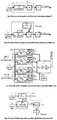
- the structural scheme S1 of the conventional flowmeters consists of a primary element EP and a secondary element ES, the primary element composed in its turn by a reference block BR which functionally provides the constant of the reference parameter X R against variation of the measured flow rate Q, and a sensitive block BS detecting the variation of the parameter X V and thus the variation of the flow rate Q.
- the reference parameter X R is kept constant against the variation in the flow rate Q by the functioning way of the block BR itself, parameter X V being variable according to the variation of the flow rate Q, and the characteristic parameter-X C is the output of the EP element, and the input to the element ES whose output parameter Q R , the rendering parameter of the measured flow rate Q, expressed at the output of the secondary element ES.
- the structural scheme S2a relating to the mono insertion flowmeters is based on an monoinsertion system SI of the sensitive block BS, in addition to the structural scheme S1, and the element EP INSERTION represents the configuration of related primary element.
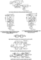
- Structural scheme S2b of the multipoint insertion flowmeters shown in Figure 3 puts in evidence an index i of the m annulus (rings) in which is imaginary divided the total area A of the measuring section, and also marks the structural blocks and related parameters for each annulus in part, respectively an index j of the n circular segments in which is imaginary divided, in its turn, each annulus (ring), this index marking also structural blocks and related parameters of each circular segment in part.
- EP 1,1 ... EP m, n represent some individual primary elements, each EP i,j having the same structure and same parameters corresponding to those indicated for element EP insert in the structural scheme S2a and corresponding to one of the circular segment of the total area A and a set of primary individual elements SEP.
- the flowmeters with auxiliary fluid comprise a set of primary elements SEP, made by a main primary element EP main , a supplementary primary element EP auxiliary , between the two elements being characteristic placed a variable fluidic resistance RFV.
- the flowmeter of this type reveals an auxiliary fluid flow q, a main characteristic parameter X Cp and an additional characteristic parameter X CS .
- the structure of the by pass type flowmeters(with closed derivation) with the generating (q) by a differential static pressure highlights a set of primary elements SEP made up by a main primary element EP and a supplementary primary element EP bypass .
- the structure of the by-pass flowmeters (with closed derivation), with generating (q) by a dynamic pressure according to structural scheme S6b of Figure 7 , highlights a set of primary elements SEP consisting of a main primary element EP main and an additional primary element EP bypass .
- the structure of the secondary element of flowmeter, scheme S-ES - of Figure 8 comprises a processing block of the output parameter of the primary part of flowmeter of BP-X C , respectively characteristic parameter X C and a transmission block BT - Q R of the parameter Q R , rendering the flow rate measured by the flowmeter, X T representing the parameter transmitted resulting after processing of the characteristic parameter X C of the block BP - X C .
- the structural scheme of the compound gauging structures CD 1 represented in Figure 9 comprises some individual flowmeters D 1 ... D n , components of the compound gauging structure and an Adder-a structural block, specific to any type of compound gauging structure, which provides the calculation of the parameter Q R , rendering the total measured flow rate Q and highlights some partial flows Q 1 .. Q n measured by flowmeters D 1 ... D n .
- the characteristic-parameter X Cj are the level of the free liquid surface upstream of the measuring section, flowmeters, which use modular range flow and respectively the values pair of free liquid surface levels, pair upstream / downstream of the Measuring section for flowmeters which use non-modular flow range.
- Structural scheme of the compound gauging structure type CD 2 shown in Figure 10 is composed of individual gauging structures D 1 ... D m components of the compound gauging structure that have a Sensitive block BS related to the compound gauging structure, common to all individual gauging structures D 1 .. D m of the compound gauging structure, and an Adder of measured partial flow rates Q 1 ...Q m , which ensures at its output the parameter Q R , respectively the rendering of the total measured flow rate Q.
- the Sensitive block BS detects the variation of the passing areas (A 1 ... A m ) of the liquid flow depending on the partial flow rates Q 1 ...
- the liquid level is measured upstream of the measuring sections achieved constructively by each structural reference block BR 1 ... BR m of the individual flowmeters D 1 ... D m in part, these blocks constructively achieving the measuring sections of the liquid flow rate, related to these individual gauging structures.
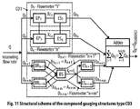
- the structural scheme of the compound gauging structure type CD 3 represented in Figure 11 is made up by a compound gauging structure type CD 1 and a compound gauging structure type CD 2 , connected in parallel, and an Adder which ensures the calculation of the total measured flow rate Q, and its rendering by the parameter Q R , by the summing up some parameters Q R1 ....Q Rn , by the summing up some parameters Q R1 ...Q Rn+m , which render some measured partial flows rates Q 1 ....Q n+m .
- some individual gauging structures D 1 ... D n are components of the structural scheme related to the compound gauging structure type CD 1
- D n+1 ... D n+m represent some individual gauging structures, components of the structural scheme related to the compound gauging structure type CD 2 .
- type CD 3 is only theoretically possible in principle, by proposing parallel coupling of a compound gauging structure of type CD 1 , with a compound gauging structure of type CD 2 under conditions in which gauging structures D 1 ... D n associated with the compound gauging structure type CD 1 are flowmeters for closed conduits.
- gauging structures D 1 ... D n associated with the compound gauging structure type CD 1 are flowmeters for closed conduits.
- practically it is difficult to make this variant because it is necessary to ensure the continuity of the total flow measuring range, which includes both the low values of the flow measuring ranges of flowmeters for closed conduits, and also the high values of the flow measuring ranges corresponding to flowmeters for open channels.
- the method provides the logical generation of appropriately coded response solutions for a set of 14 criteria for flowmeters, respectively 17 criteria, for compound gauging structures, grouped in 5 "criteria groups" of a constructive-functional nature that can define in a complete manner the construction and operation of any type of conventional or unconventional flowmeter, or any compound gauging structures.
- criteria groups are:
- the method of unitary synthesis and design of any type of flowmeter is based on the following of a procedural sequence of several processing stages, each stage assuming browsing of algorithm able steps which proves the essence of the computer program that implements the present method.
- the first stage envisages creating and storing of the unitary logical reference network, for configuring a new basic type of flowmeter, network made up of:
- Second defining stage of method involves entry and validation of the "set of initial configuration data" of a new basic type of flowmeter.
- the third stage involves establishing, for the flowmeter to be configured, the mode of analytical expression of the measuring flow rate and the structural group embodying its structural ensemble
- a first step it is checked whether can be validated the "set of input data" as usable for starting configuration and design of a new basic type of flowmeter, and in negative case being modified those input data which do not allow selection of logically consistent solutions among those indicated in Table 2, as possible in this respect, according to the criteria no. 1, 2, 3.
- the flowmeter has the overall structural scheme of a conventional type, it is used the "conventional structure" according to the solution related to the criterion no. 4 of Table no. 2, respectively structural scheme S1 shown in Figure 1 .
- the fourth stage is intended to configure the primary part of the flowmeter, for both conventional flowmeters and unconventional flowmeters.
- This stage provides in a first sub-stage the setting up of the structural type for configuration of the primary part of the flowmeter.
- the fourth stage then proceeds with the design of the primary part of the flowmeter, provided by a primary element EP (for flowmeters with “conventional structure”) respectively a set of primary elements SEP (for flowmeters with “unconventional structure”) set made by connections between two or more EP or between one or more EP with “conventional structure” from Figure 1 coupled with an auxiliary device (insertion system, fluidic resistance) according to the followed variant of "unconventional structure”.
- a primary element EP for flowmeters with "conventional structure
- SEP for flowmeters with "unconventional structure”
- Step 3-DC After modifying the constructive solution initially chosen for BR, and then reprocessing the steps 3-DC ... 10-DC.
- Step 5 If the result of the new verification is positive, proceed to Stage 5, and if it is negative, return to Step 7- DC, after modifying the constructive solution initially chosen for BS, and then reprocess steps 7- DC ... 10-DC.
- step 5 If in the end the test result is positive, go to Stage 5, and if negative go back to step 2-DN and reprocess steps 7-DC ....9-DC, then proceed to step 3-DN (if required by the specification from step 2-DN) and then with steps 4-DN and 5-DN, after changing the constructive solution initially chosen for BS to one or more EPs in the SEP. If the result of the check is finally positive, go to Stage 5, if not, go back to step 7-DC related to step 2-DN, repeating the same cycle, until an affirmative response is obtained, following the verification in step 5-DN.
- Stage 5 involves the configuration of the secondary part - the secondary element ES - of the flowmeter, which in turn has as a first sub- stage the configuration of overall structural scheme of ES, a second sub-stage the unitary constructive design of the processing block BP - and then a third sub- stage, the unitary constructive design of the transmission block BT-Qp.
- Step 3 takes place the achievement of BP- , according to that basic solution corresponding to criterion no.13 of Table 2, which corresponds to the analysis from the previous step, using a constructive variant correlated with the structural scheme of the flowmeter assembly shown in Table 6.
- step 4 of the stage it is constructively achieved the transmission block BT-Qp, by choosing a solution among those related to criterion no. 14 of Table 2.
- Stage 6 envisages the achievement of the structural assembly of the new type of flowmeter configured, by connecting the constructive solutions obtained in the previous steps, and involves firstly, the editing of the overall detailed constructive structural scheme finalized for the new basic type of the flowmeter configured, and finally setting the name of the new basic type of flowmeter, depending on the constructive solution used for the design of the primary part thereof.
- the method for unitary synthesis and design of compound gauging structures involves, in a similar manner with that used for individual flowmeters, conducting several procedural working stages, where each stage suppose proceeding of algorithm based procedural steps which constitutes the essence of the computer program which implements the said method.
- Said network is built up of:
- the first three groups of criteria mentioned above include, with reference to the flowmeters composing the compound gauging structure, the 14 criteria (questions) and the corresponding response solutions previously indicated, that ensure the unitary synthesis and design of the flowmeters.
- the second stage involves input and validation of the "set of initial configuration data" of a new basic type of compound gauging structure, whereby after, it is checked if the inputted "initial data for configuration and design", are the minimum needed, by responding to the provisions of criteria 1, 2, 3.1, 3.2 of Table 7, and in the negative case being necessary to complete the "set of initial configuration data", with the missing data, against the previsions of criteria 1,2, 3.1,3.2 of Table 7.
- the third stage provides the setting for the component gauging structures of the future compound gauging structure, of the analytical mode of expression of flow rate and of the type of the structure.
- a first sub-stage it is established, on the one hand the analytical mode of expression of the measured flow rate and on the other hand, the type of structural group as " conventional structure” or “unconventional structure”, chosen to be within the structural schemes of the component gauging structure of the compound gauging structure to be set up.
- the component gauging structures of the compound gauging structure must have the structural scheme of the conventional type and the selection of the component gauging structures is, among those which have a "conventional structure" according to the solution code 4.1 .1 related to criterion no. 4.1 of Table 7, respectively Schematic scheme S1 from Figure1 .
- the component gauging structures of the compound gauging structure must accordingly be "conventional flowmeters”.
- the component gauging structures of the compound gauging structure have a structural scheme of unconventional type, and the selection of the component gauging structures, is made among those having the structure in accordance with, those of variants of "unconventional structural scheme"S2a, S2b, S4, S5, or S6b corresponding to solution or solutions previously chosen for analytical expression of flow rate within the solution group code 3.1.2 of Table 7.
- the fifth stage consists in validating the novelty of the configured compound gauging structure, verifying that the configured compound gauging structure is among those achieved so far and shown in Table 8, and in the negative case it is proceeded to the editing of the detailed constructive scheme for the new basic type of set up compound gauging structure and the denomination of the new type of compound gauging structure.
- the component gauging structures found in existing combinations are replaced with other gauging structures, among those already pre-selected as appropriate, by browsing the previous stages. The cycle is repeated until it is not found the compound gauging structure as set up in Table 8.
Landscapes
- Physics & Mathematics (AREA)
- Fluid Mechanics (AREA)
- General Physics & Mathematics (AREA)
- Measuring Volume Flow (AREA)
Claims (6)
- Computerimplementiertes Verfahren zur einheitlichen Synthese und zum Entwurf von Durchflussmessgeräten und von Verbindungmessstrukturen, dadurch gekennzeichnet, dass die Erzielung eines beliebigen Grundtyps von Durchflussmessgeräte.n konventionelle oder unkonventionelle, sowohl unter den existierenden, als auch unter den logisch vorstellbaren und erreichbaren, umfasst die folgenden Stufen:Stufe 1 - Erstellen und Speichern des einheitlichen Referenzlogiknetzwerks, das zum Synthese eines neues Durchflussmessgerätetyps erforderlich ist;Stufe 2 - Eingabe und Validierung des "Satzes der anfänglichen Einrichtungsdaten" eines neuartigen Grundtyps von Durchflussmessgerätes;Stufe 3 - Festlegung, für den zu synthetisierenden Durchflussmessgerätes der analytischen Ausdrucksweise der gemessenen Durchflussmenge und der Baugruppe, in die das Gesamtstrukturschema des Durchflussmessgerätes eingepasst werden könnte;Stufe 4 - Aufbau des Primärteils des Durchflussmessgerätes, bei dem der Strukturtyp des Primärteils des Durchflussmessgerätes durch ein Primärelement EP festgelegt wird (für "konventionelle Struktur" aus dem Referenzblock BR und dem empfindlichen Block BS) jeweils durch einen Satz von Primärelementen SEP (für "unkonventionelle Durchflussmessgeräte", aufgebaut durch die Verbindung zwischen mehreren EP oder durch die Verbindung zwischen einem oder zwei EP und einer Hilfsvorrichtung) und weiter für "konventionelle Durchflussmessgeräte" "mit dem einheitlichen Aufbau des Primärelements EP, dem Aufbau der Gesamtstruktur des Primärelements EP, dem einheitlichen konstruktiven Aufbau des Referenzblocks BR, dem einheitlichen konstruktiven Aufbau des sensitiven Blocks BS und der Validierung der Neuheit des synthetisierte EP - Lösung, und für "unkonventionelle Durchflussmessgerätes" das Einrichten der Strukturkaufbau von SEP, das Entwerfen der Komponentenprimärelemente EP, das Aufbau der Hilfsvorrichtungen (zur einige strukturelle Varianten), das konstruktive und informative Erreichen der Verbindungen zwischen den die SEP bildenden Hauptelementen EP, gefolgt von der Validierung der Neuheit der Lösung der synthetisierten SEP;Stufe 5 - Aufbau des Sekundärelements ES des Durchflussmessgerätes bestehend aus dem Aufbau des Gesamtstrukturdiagramms von ES, dem einheitlichen konstruktiven Aufbau des Verarbeitungsblocks BP-XC und dem einheitlichen konstruktiven Aufbau des Übertragungsblocks BT-QR;Stufe 6 - Erzielung der Gesamtstrucktur des neuartigen aufgebauten Durchflussmessgerätes durch Verbindung der konstruktiven Lösungen, die in den vorherigen Stufen erhalten wurden;wobei- die Implementierung von Stufe 2, die folgenden Verfahrensschritte umfasst:Schritt 1 - Eingabe des "Satzes von anfänglichen Struktur- und Konstruktionsdaten" eines neuen Grundtyps eines Durchflussmessgerätes, der die Kriterien Nr. 1, 2, 3 von Tabelle 2 und die Bestimmungen von Tabelle 2A erfüllt;Schritt 2: Validierung der "Eingabedatensatz", der zum Starten der Kofigurieren und des Entwerfen eines neuen Grundtyps von Durchflussmessgeräten verwendet werden kann, indem Sie die fehlenden Daten ausfüllen und die Eingabedaten ändern, aus denen keine logisch konsistenten Lösungen ausgewählt werden können die anderen in Tabelle 2 gezeigten Lösungen sind diesbezüglich nach den Kriterien Nr. 1, 2, 3 möglich;- die Implementierung von Stufe 3, die folgenden Verfahrensschritte umfasst:Schritt 1 - Fortlaufende Auswahl unter den Lösungen in Bezug auf die Kriterien Nr. 1, 2, 3 der Tabelle 2 von denen, die unter Verwendung der "ErstAufbaus- und Konstruktionsdaten" die vollständige und kohärente Charakterisierung der analytischen Ausdrucksweise der Durchflussmenge durchführen, die durch die Aufbau und die Konstruktion sichergestellt werden muss vom neuen Grundtyp von Durchflussmesgeräten;Schritt 2 - Aufbau der Strukturgruppe, die zu dem neu zum synthetisierten Durchflussmesser passt, gemäß der oben angegebenen analytischen Ausdrucksweise der Durchflussmenge and danach, bei einem konventionellen Durchflussmessgeräten wird dann der konventionelle Entwerfen gemäß verwendet die Lösung bezog sich auf das Kriterium Nr. 4 in der Tabelle Nr. 2, jeweils die Strukturschema S1 gezeigt in Fig. 1 , und im Fall eines unkonventionellen Durchflussmessgerätes wird die "unkonventionelle Struktur" verwendet, die zu der Gruppe von Strukturen gehört, die sich auf das Kriterium Nr. 4 der Tabelle 2 beziehen, wobei eines der Strukturschema S2a, S2b, S4, S5, S6a, S6b ausgewählt wird, die in Fig. 2...7 gezeigt sind;- die Implementierung der Stufe 4 die folgenden Schritte umfasst:A. Für konventionelle DurchflussmessgeräteSchritt 1-DC -Identifizieren des Primärelements EP als das strukturelle Art des Erreichens des Primärteils des Durchflussmessgerätes gemäß der Lösung in Bezug auf das Unterkriterium Nr. 5.1 von Tabelle 2, das dem Strukturdiagramm S1 von Fig. 1 entspricht;Schritt 2-DC - Entwerfen der Gesamtaufbau des primären Elements EP, bestehend aus dem Referenzblock BR und dem sensitiven Block BS gemäß der zu Teilkriterium Nr. 5.1 der Tabelle 2 entsprechend dem Strukturdiagramm S1 der Figur 1;Schritt 3-DC- Festlegen des tatsächlichen physikalischen Parameters, der durch den Referenzparameter XR unter den in Tabelle 1 angegebenen Varianten gemäß den zuvor festgelegten Antwortlösungen entsprechend den Kriterien Nr. 1 und 2 von Tabelle 2 erreicht werden soll;Schritt 4 - DC - Entwerfen der Grundlösung zur Erreichung des Referenzblocks BR unter den in Tabelle 2 angegebenen Varianten, entsprechend dem Unterkriterium Nr. 6.2, durch Vermeiden der logisch inkompatiblen Sequenzen unter den in Tabelle 4 gezeigten Lösungen;Schritt 5-DC - Konstruktiver Entwerfen des Referenzblocks BR durch sequentielles Festlegen der konstruktiven Lösungen, die den Kriterien Nr. 7 und 8 in Tabelle 2 entsprechen, und Korrelieren dieser Lösungen durch Vermeiden der logisch inkompatiblen Folgen unter den in Tabelle 5 gezeigten Lösungen;Schritt 6-DC - Bestimmen des tatsächlichen physikalischen Parameters, der am Ausgang des Referenzblocks BR zu erreichen ist (nämlich der "variable Parameter XV"), unter den Antwortmöglichkeiten, die sich auf das Kriterium Nr. 9 der Tabelle 2 beziehen, entsprechend dem Typ von vorher eingestelltem BR muss die Lösung für XV mit der oben für XR angegebenen Lösung korreliert werden, um innerhalb der in Tabelle 1 angegebenen Korrelationsvarianten zu liegen;Schritt 7 - DC - Beginn des Entwurfs der BS durch Auswahl der konstruktiven Lösung zum Verbinden des BR mit der BS unter den Antwortvarianten, die sich auf das Kriterium 10 in Tabelle 2 beziehen;Schritt 8-DC- Einstellen des tatsächlichen physikalischen Parameters zum Erreichen des Ausgangsparameters von BS (oder des "charakteristischen Parameters XC"), beginnend mit der Untersuchung der in Tabelle 2A gezeigten Antwortlösungen, bezogen auf das Kriterium Nr. 11 von Tabelle 2 entsprechend den zuvor gewählten Lösungen für den konstruktiven Typ des Blocks BR und für die Variante von XV; Schritt 9 - DC - Fertigstellung der Aufbau und des Entwurfs von BS durch Auswahl der Antworten in Bezug auf die Kriterien Nr. 11 und 12 der Tabellen 2 und 2A der entsprechenden konstruktiven Aufbauslösungen;Schritt 10 - DC - Überprüfen, ob die für das Primärelement EP des "konventionellen Durchflussmessgerätes" eingerichtete Lösung neu ist und nicht mit den vorhandenen Durchflussmessgeräten übereinstimmt und wenn das Ergebnis positiv ist, fahren Sie mit Schritt 5 fort, und wenn das Ergebnis negativ ist, kehren Sie zurück Mit Schritt 3-DC fortfahren, nachdem die ursprünglich für BR gewählte konstruktive Lösung geändert und die Schritte 3-DC ... 10-DC gelöst wurden, das Ergebnis überprüfen und mit Schritt 5 fortfahren, wenn das Ergebnis positiv ist, und wenn es negativ ist, zurückkehren In Schritt 7-DC werden nach dem Ändern der konstruktiven Lösung, die ursprünglich für BS gewählt wurde, und dem Zyklus der Schritte 7-DC ... 10-DC erneut die gesamten Vorgänge wiederholt, bis die Verarbeitung von Schritt 10 abgeschlossen ist eine positive Antwort erhalten, wenn mit Schritt 5 fortgefahren werden kann;B. Für unkonventionelle Durchflussmessgeräten:Schritt 1-DN - Generische Identifizierung des Satzes der Primärelemente SEP als struktureller Modus zur Erzielung des Primärteils des Durchflussmessgerätes bzw. der Auswahl seiner konkreten strukturellen Aufbau unter den Varianten der Antwortlösungen, die dem in Tabelle 2 angegebenen Unterkriterium 5.2 entsprechen und den in den 2, 3, 4, 5, 6, 7 nacheinander gezeigten Strukturschemata S2a, S2b, S4, S5, S6a, S6b entsprechen;Schritt 2-DN - Einheitlicher Entwerfen jeder EP-Komponente des Primärelements der spezifischen Struktur, die zuvor für den Satz von Primärelementen SEP des zu konfigurierenden unkonventionellen Durchflussmessgerätes eingerichtet wurde, durch Durchsuchen derselben Schritte 2-DC ... 9-DC entspricht der Aufbau konventionellen Durchflussmessgeräten und geht dann zu Schritt 3-DN für SEP, das in den Strukturvarianten S2a, S2b, S4, S5, S6b erzielt wurde, oder direkt zu Schritt 4-DN für SEP, das in der Strukturvariante erzielt wurde S6a;Schritt 3-DN - Entwurf von Vorrichtungen, die sich auf einige der Strukturvarianten von SEP beziehen, wie folgt: das Einfügungssystem SI für die Strukturvarianten S2a, S2b, S6b und den variablen Fluidwiderstand RFV für die Strukturvarianten S4, S5;Schritt 4-DN - Erzielen der konstruktiven und informativen Verbindungen zwischen den Primärelementen EP, wobei die Komponenten des Satzes von Primärelementen SEP zuvor gemäß seinem spezifischen Strukturschema für diesen Satz einen unkonventionellen Durchflussmesser eingerichtet haben;Schritt 5- DN- Überprüfen, ob die für den Satz der Primärelemente SEP des "unkonventionellen Durchflussmessgerätes" konfigurierte Lösung neu ist und nicht mit den vorhandenen Durchflussmessgeräten übereinstimmt. Wenn das Ergebnis positiv ist, man fahrt mit Schritt 5 fort und wenn das Ergebnis negativ ist kehrt zu Schritt 2-DN zurück, und die Schritte 3-DC ... 9-DC werden erneut ausgeführt. Fahren Sie dann mit Schritt 3-DN fort, falls dies durch die Ausführung von Schritt 2-DN vorgeschrieben ist, und fahren Sie dann mit den Schritten 4 bis 4 fort. DN, 5-DN nach dem Modifizieren der konstruktiven Lösung, die ursprünglich für den Block BR für das eine oder die mehreren EP des SEP gewählt wurde, und Überprüfen, ob das Endergebnis positiv ist, in welchem Fall es zu Stufe 5 übergeht, während es, wenn es negativ ist, zurückkehrt Fahren Sie mit Schritt 2-DN fort, und fahren Sie mit Schritt 7-DC ... 9-DC fort. Fahren Sie dann mit Schritt 3-DN fort, falls dies durch die Ausführung von Schritt 2-DN erforderlich ist, und fahren Sie dann mit Schritt 4-DN und fort 5-DN nach dem Ändern der konstruktiven Lösung, die ursprünglich für BS bei einem oder mehreren EP in der SEP gewählt wurde, so dass, wenn das Ergebnis positiv ist, zu Stufe 5 übergegangen wird, und, falls nicht, zu Schritt 7-DC zurückgekehrt wird zu Schritt 2-DN, indem der gleiche Zyklus wiederholt wird, bis eine positive Antwort erhalten wird, die der Bedingung in Schritt 5-DN folgt;- die Implementierung der Stufe 5 die konstruktive Synthese des Sekundärteils des Durchflussmessgerätes bzw. des Sekundärelements ES im Anschluss an das Allgemeine umfasst Strukturschema S-ES, gezeigt in Fig. 8, durch Erreichen des Verarbeitungsblocks BP-XC bzw. des Übertragungsblocks BT-QR durch Auswahl von Grundlösungen unter denjenigen, die sich auf die Kriterien Nr. 13, 14 von Tabelle 2 beziehen, welche sind in Tabelle 6 angegeben und müssen mit dem anfänglich eingestellten Gesamtstrukturschema des Durchflussmessers korreliert werden.
- Computerimplementiertes Verfahren zur einheitlichen Synthese und zum Entwurf von Durchflussmessgeräten und von Verbindungmessstrukturen nach Anspruch 1, dadurch gekennzeichnet, dass die Implementierung der Stufe 1 die Erstellung und Speicherung des "einheitlichen Referenzlogiknetzwerks" umfasst, das zur Erzielung der einheitlichen Aufbau und zur Entwicklung neuer Grundtypen von Durchflussmessgeräten benötigt wird .
- Computerimplementiertes Verfahren zur einheitlichen Synthese und zum Entwurf von Durchflussmessgeräten und von Verbindungmessstrukturen nach Anspruch 1, dadurch gekennzeichnet, dass die Implementierung von Stufe 6 die Bearbeitung des detaillierten konstruktiven Gesamtstrukturschemas umfasst, das für den neuen Grundtyp des konfigurierten Durchflussmess gerätes fertiggestellt und benannt wird der neue Grundtyp des Durchflussmessgerätes, entsprechend der konstruktiven Lösung, die für die einheitliche Aufbau und Entwurf seines Primärteils verwendet wird.
- Computerimplementiertes Verfahren zur einheitlichen Synthese und zum Entwurf von Durchflussmessgeräten und von Verbindungmessstrukturen, dadurch gekennzeichnet, dass die Erreichung einer beliebigen Verbindungmessstruktur umfasst die folgenden Stufen:Stufe 1 - Erstellen und Speichern des einheitlichen logischen Referenznetzwerks zum Synthese einer neuen Verbindungmessstruktur;Stufe 2 - Einführung und Validierung des "Satzes von ErstAufbausdaten" eines neuen Grundtyps einer Verbindungmessstruktur;Stufe 3 - Festlegen, für die Messstrukturkomponente des zukünftiges Verbindungmessstruktur des analytischen Ausdrucksmodus der Durchflussmenge und des beteiligtes Strukturtyps , wobei zum einen Seite der analytische Ausdrucksmodus der messenden Durchflussmenge festgelegt wird und andererseits die Einstellung des gewählten Strukturtyps der Strukturschemata der Messstrukturkomponente der zusammengesetzten Verbindungmessstrukturenen ;Stufe 4 -Entwerfen vom neuen Verbindungmessstruktur CD;Stufe 5 - Validierung der Neuheit der synthetisierten Struktur des Verbindungmessstruktur;wobei- zum Zweck der Implementierung der Stufe 2, die Eingabe des Satzes von Anfangsdaten für die Aufbau und die strukturelle Konstruktion eines neuen Grundtyp des Verbindungmessstruktur, der die Kriterien Nr. 1, 2, 3 von Tabelle 7 erfüllen muss, durchgeführt wird, Validierung des Eingabedatensatzes, der für die einheitliche Aufbau und den Entwurf eines neuen Grundtyps des Verbindungmessstruktur verwendet werden kann, und falls vorhanden wird nicht validiert, indem die Eingabedaten geändert werden, die keine Auswahl logisch miteinander übereinstimmender Lösungen von Tabelle 7 gemäß den Kriterien 1, 2, 3 ermöglichen;- zum Zweck der Implementierung der Stufe 3, die nächsten Verfahrensschritten fortgefahren wird:Schritt 1 -Die aufeinanderfolgende Auswahl unter den Lösungen nach den Kriterien Nr. 1, 2, 3.1 derjenigen, die zu den "ErstAufbaus- und Auslegungsdaten" passen und die vollständige und konsistente Charakterisierung des analytischen Ausdrucks der gemessenen Durchflussmenge in der von diesen "Daten" geforderten Weise durchführen, die von den Durchflussmessern gewährleistet werden müssen, die werden dann als Komponenten des zusammengesetztes Verbindungmessstruktur ausgewählt, um sie zu synthetisieren;Schritt 2 - Überprüfen die Bedingung, falls sie der für die analytische Darstellung der Durchflussmenge gewählten Lösung entspricht, die Messstrukturen des zusammengesetztes verbindungmessstruktur haben den konventionellen Typ des Strukturschemas (Struktur);Schritt 3 -Für den Fall eines konventionellen Typs des Strukturschemas werden das Verbindungmessstruktur unter jenen mit einer "konventionellen Struktur" gemäß der Lösung ausgewählt, die dem Kriterium Nr. 4 von Tabelle 7, bzw. Strukturschema S1 von 1, und im Fall eines Strukturschemas von unkonventionellem Typ werden das Verbindungmessstruktur unter jenen mit der Struktur gemäß den "Varianten des unkonventionellen Strukturschemas" S2a, S2b ausgewählt, S4, S5, S6a oder S6b innerhalb des Lösungsgruppencodes 3.1.2 von Tabelle 7 entsprechend der zuvor für den analytischen Ausdruck der Durchflussrate ausgewählten Lösung;- zum Zweck der Implementierung der Stufe 4, die folgenden Verfahrensschritten fortgefahren wird:wobeiSchritt 1 - Auswahl der Art des Strukturschemas bis folgen in der Synthese der zusammengesetzten Verbindungmessstrukturen unter den Lösungen CD1, CD2 oder CD3, bezogen auf das Kriterium Nr. 4.2 von Tabelle 7;Schritt 2 - Bestimmung die Lösungen für das Kriterium Nr. 4.2 von Tabelle 7, der Art der konstruktiven Lösung, die bei der Erzielung der zu synthetisierenden CD zu befolgen ist, die mit den vorherigen Optionen übereinstimmt: die strukturelle Art der Verbindungmessstrukturen, konventionell oder unkonventionell, bzw. die Art der messende Flüssigkeit fließt;Schritt 3 - Aufbau des zusammengesetztes Verbindungmessstruktur durch Auswahl des komponentes Verbindungmessstruktur unter den vorab ausgewählten, indem die vorherigen Schritte ausgeführt und mit der entsprechenden Kopplung abgeschlossen werden;Schritt 4 - Fertigstellung der Aufbau der zusammengesetzten Verbindungmessstrukturen durch Lösen der Konditionierungen, die durch die Kriterien Nr. 15, 16 und 17 von Tabelle 7 und unter Verwendung der angegebenen verwandten Lösungen für sie;- zum Zweck der Implementierung der Stufe 5, wird ob das synthetisiertes Verbindungmessstruktur innerhalb der bisher erreichten und in angegebenen liegt Tabelle 8 geprüft, und wenn dies der Fall ist, werden die Komponentendurchflussmesser, die in vorhandenen zusammengesetzten Verbindungmessstrukturen zu finden sind, durch andere Verbindungmessstrukturen ersetzt, die unter den bereits vorab als angemessen ausgewählten ausgewählt wurden, bis die vorherigen Schritte abgeschlossen sind.
- Computerimplementiertes Verfahren zur einheitlichen Synthese und zum Entwurf von Durchflussmessgeräten und von Verbindungmessstrukturen nach Anspruch 4, dadurch gekennzeichnet, dass zum Zweck der Implementierung der Stufe 1, wird mit dem Erstellen und Speichern des Referenz-Einheits-Logiknetzwerks notwendigen zur einheitlichen Synthese und zum Entwurf neuer Grundtypen von Durchflussmesserkombinationen " fortgefahren.
- Computerprogrammprodukt zur Durchführung des Verfahrens zur einheitlichen Synthese und zum Entwurf von Durchflussmessgeräten nach Anspruch 1 und von Verbindungmessstrukturen nach Anspruch 4.
Applications Claiming Priority (1)
| Application Number | Priority Date | Filing Date | Title |
|---|---|---|---|
| ROA201700095A RO132778A2 (ro) | 2017-02-20 | 2017-02-20 | Metodă implementată cu ajutorul calculatorului, pentru configurarea şi proiectarea unitară a debitmetrelor şi a combinaţiilor de debitmetre |
Related Parent Applications (1)
| Application Number | Title | Priority Date | Filing Date |
|---|---|---|---|
| RO201700095 Previously-Filed-Application | 2017-02-20 |
Publications (3)
| Publication Number | Publication Date |
|---|---|
| EP3364159A2 EP3364159A2 (de) | 2018-08-22 |
| EP3364159A3 EP3364159A3 (de) | 2019-01-30 |
| EP3364159B1 true EP3364159B1 (de) | 2020-01-22 |
Family
ID=61557009
Family Applications (1)
| Application Number | Title | Priority Date | Filing Date |
|---|---|---|---|
| EP18020055.2A Active EP3364159B1 (de) | 2017-02-20 | 2018-02-12 | Computerimplementiertes verfahren zur einheitlichen synthese und zum entwurf von durchflussmessgeräten und von verbindungmessstrukturen |
Country Status (2)
| Country | Link |
|---|---|
| EP (1) | EP3364159B1 (de) |
| RO (1) | RO132778A2 (de) |
Cited By (1)
| Publication number | Priority date | Publication date | Assignee | Title |
|---|---|---|---|---|
| EP4001856A1 (de) | 2020-11-24 | 2022-05-25 | Motit, Horia Mihai | Reaktionsdurchflussmessgerät ohne bewegliche teile in einzel-, bypass- bzw. erweiterter konfiguration und darauf basiertes verfahren zur durchflussmessung |
Families Citing this family (2)
| Publication number | Priority date | Publication date | Assignee | Title |
|---|---|---|---|---|
| CN114739487B (zh) * | 2022-02-23 | 2025-04-11 | 上海市燃气设备计量检测中心有限公司 | 一种超声波燃气表的抗干扰检测方法及系统 |
| EP4471385B1 (de) * | 2023-05-29 | 2025-09-03 | Motit, Horia Mihai | Funktionsverfahren zur linearisierung der strömungskraftabhängigkeit auf das reaktionselement eines durchflussmessgeräts und damit gebildetes lineares reaktionsmessgerät |
-
2017
- 2017-02-20 RO ROA201700095A patent/RO132778A2/ro unknown
-
2018
- 2018-02-12 EP EP18020055.2A patent/EP3364159B1/de active Active
Non-Patent Citations (1)
| Title |
|---|
| None * |
Cited By (1)
| Publication number | Priority date | Publication date | Assignee | Title |
|---|---|---|---|---|
| EP4001856A1 (de) | 2020-11-24 | 2022-05-25 | Motit, Horia Mihai | Reaktionsdurchflussmessgerät ohne bewegliche teile in einzel-, bypass- bzw. erweiterter konfiguration und darauf basiertes verfahren zur durchflussmessung |
Also Published As
| Publication number | Publication date |
|---|---|
| EP3364159A2 (de) | 2018-08-22 |
| RO132778A2 (ro) | 2018-08-30 |
| EP3364159A3 (de) | 2019-01-30 |
Similar Documents
| Publication | Publication Date | Title |
|---|---|---|
| EP3364159B1 (de) | Computerimplementiertes verfahren zur einheitlichen synthese und zum entwurf von durchflussmessgeräten und von verbindungmessstrukturen | |
| USRE36597E (en) | Apparatus and method for measuring two- or three-phase fluid flow utilizing one or more momentum flow meters and a volumetric flow meter | |
| US3701280A (en) | Method and apparatus for determining the supercompressibility factor of natural gas | |
| US6681189B1 (en) | Method and system for determining flow rates and/or fluid density in single and multiple-phase flows utilizing discharge coefficient relationships | |
| EP2801797A1 (de) | Dampfströmungsmessvorrichtung und messverfahren dafür | |
| US3705979A (en) | Method of processing production well logging data | |
| CN107330218A (zh) | 轴销式传感器及其径向力标定与计算方法、装置和系统 | |
| CN106225862A (zh) | 气体流量简捷补偿方法 | |
| CN105784707A (zh) | 一种基于高速摄影技术的气液两相流测量方法和装置 | |
| CN112284471B (zh) | 通用差压式气体质量流量测量方法及其变送器、计算系统 | |
| EP2843376A1 (de) | Gasflussmesserprogramm einer verengungsvorrichtung und durchflussmessverfahren sowie durchflussmessvorrichtung damit | |
| CN109917152A (zh) | 一种垂线平均流速测量方法 | |
| McKelvey et al. | Turbulent motion, mixing, and kinetics in a chemical reactor configuration | |
| US3232104A (en) | Mass flowmeter | |
| GB2638564A (en) | Virtual flow metering using acoustics | |
| US3266309A (en) | Mass flowmeter | |
| CN101187660A (zh) | 双槽式孔板型混输计量装置 | |
| Raghavan | Some theoretical results useful in analyzing well performance under solution-gas drive | |
| Dayev | Theoretical modelling of natural gas unsteady flow rate measurement using variable differential pressure method | |
| Lari et al. | Error correction of a coriolis mass flow meter in two-phase flow measurment using Neuro-Fuzzy | |
| US9441995B2 (en) | System and method for monitoring a bi-phase fluid | |
| CN106323366A (zh) | 一种基于射线衰减技术的气液两相流测量方法和装置 | |
| Han et al. | Void fraction measurement method in gas/liquid two-phase stratified flow | |
| KR101522243B1 (ko) | 터빈을 이용한 질량유량측정 프로그램 및 이를 이용한 측정장치 | |
| Haldun Ünalmis | Flow measurement optimization using surface measurements and downhole sound speed measurements from local or distributed acoustic sensors |
Legal Events
| Date | Code | Title | Description |
|---|---|---|---|
| PUAI | Public reference made under article 153(3) epc to a published international application that has entered the european phase |
Free format text: ORIGINAL CODE: 0009012 |
|
| STAA | Information on the status of an ep patent application or granted ep patent |
Free format text: STATUS: THE APPLICATION HAS BEEN PUBLISHED |
|
| AK | Designated contracting states |
Kind code of ref document: A2 Designated state(s): AL AT BE BG CH CY CZ DE DK EE ES FI FR GB GR HR HU IE IS IT LI LT LU LV MC MK MT NL NO PL PT RO RS SE SI SK SM TR |
|
| AX | Request for extension of the european patent |
Extension state: BA ME |
|
| PUAL | Search report despatched |
Free format text: ORIGINAL CODE: 0009013 |
|
| AK | Designated contracting states |
Kind code of ref document: A3 Designated state(s): AL AT BE BG CH CY CZ DE DK EE ES FI FR GB GR HR HU IE IS IT LI LT LU LV MC MK MT NL NO PL PT RO RS SE SI SK SM TR |
|
| AX | Request for extension of the european patent |
Extension state: BA ME |
|
| RIC1 | Information provided on ipc code assigned before grant |
Ipc: G01F 1/00 20060101AFI20181221BHEP |
|
| STAA | Information on the status of an ep patent application or granted ep patent |
Free format text: STATUS: REQUEST FOR EXAMINATION WAS MADE |
|
| 17P | Request for examination filed |
Effective date: 20190219 |
|
| RBV | Designated contracting states (corrected) |
Designated state(s): AL AT BE BG CH CY CZ DE DK EE ES FI FR GB GR HR HU IE IS IT LI LT LU LV MC MK MT NL NO PL PT RO RS SE SI SK SM TR |
|
| GRAP | Despatch of communication of intention to grant a patent |
Free format text: ORIGINAL CODE: EPIDOSNIGR1 |
|
| STAA | Information on the status of an ep patent application or granted ep patent |
Free format text: STATUS: GRANT OF PATENT IS INTENDED |
|
| INTG | Intention to grant announced |
Effective date: 20190711 |
|
| RIN1 | Information on inventor provided before grant (corrected) |
Inventor name: MOTIT HORIA MIHAI |
|
| GRAS | Grant fee paid |
Free format text: ORIGINAL CODE: EPIDOSNIGR3 |
|
| GRAJ | Information related to disapproval of communication of intention to grant by the applicant or resumption of examination proceedings by the epo deleted |
Free format text: ORIGINAL CODE: EPIDOSDIGR1 |
|
| GRAL | Information related to payment of fee for publishing/printing deleted |
Free format text: ORIGINAL CODE: EPIDOSDIGR3 |
|
| GRAJ | Information related to disapproval of communication of intention to grant by the applicant or resumption of examination proceedings by the epo deleted |
Free format text: ORIGINAL CODE: EPIDOSDIGR1 |
|
| GRAL | Information related to payment of fee for publishing/printing deleted |
Free format text: ORIGINAL CODE: EPIDOSDIGR3 |
|
| STAA | Information on the status of an ep patent application or granted ep patent |
Free format text: STATUS: REQUEST FOR EXAMINATION WAS MADE |
|
| INTG | Intention to grant announced |
Effective date: 20190711 |
|
| INTC | Intention to grant announced (deleted) | ||
| GRAP | Despatch of communication of intention to grant a patent |
Free format text: ORIGINAL CODE: EPIDOSNIGR1 |
|
| STAA | Information on the status of an ep patent application or granted ep patent |
Free format text: STATUS: GRANT OF PATENT IS INTENDED |
|
| INTG | Intention to grant announced |
Effective date: 20191108 |
|
| GRAA | (expected) grant |
Free format text: ORIGINAL CODE: 0009210 |
|
| STAA | Information on the status of an ep patent application or granted ep patent |
Free format text: STATUS: THE PATENT HAS BEEN GRANTED |
|
| AK | Designated contracting states |
Kind code of ref document: B1 Designated state(s): AL AT BE BG CH CY CZ DE DK EE ES FI FR GB GR HR HU IE IS IT LI LT LU LV MC MK MT NL NO PL PT RO RS SE SI SK SM TR |
|
| REG | Reference to a national code |
Ref country code: GB Ref legal event code: FG4D |
|
| REG | Reference to a national code |
Ref country code: CH Ref legal event code: EP |
|
| REG | Reference to a national code |
Ref country code: RO Ref legal event code: EPE |
|
| REG | Reference to a national code |
Ref country code: AT Ref legal event code: REF Ref document number: 1227194 Country of ref document: AT Kind code of ref document: T Effective date: 20200215 |
|
| REG | Reference to a national code |
Ref country code: IE Ref legal event code: FG4D |
|
| REG | Reference to a national code |
Ref country code: DE Ref legal event code: R096 Ref document number: 602018002035 Country of ref document: DE |
|
| PGFP | Annual fee paid to national office [announced via postgrant information from national office to epo] |
Ref country code: RO Payment date: 20200205 Year of fee payment: 3 |
|
| REG | Reference to a national code |
Ref country code: NL Ref legal event code: MP Effective date: 20200122 |
|
| REG | Reference to a national code |
Ref country code: LT Ref legal event code: MG4D |
|
| PG25 | Lapsed in a contracting state [announced via postgrant information from national office to epo] |
Ref country code: FI Free format text: LAPSE BECAUSE OF FAILURE TO SUBMIT A TRANSLATION OF THE DESCRIPTION OR TO PAY THE FEE WITHIN THE PRESCRIBED TIME-LIMIT Effective date: 20200122 Ref country code: NO Free format text: LAPSE BECAUSE OF FAILURE TO SUBMIT A TRANSLATION OF THE DESCRIPTION OR TO PAY THE FEE WITHIN THE PRESCRIBED TIME-LIMIT Effective date: 20200422 Ref country code: NL Free format text: LAPSE BECAUSE OF FAILURE TO SUBMIT A TRANSLATION OF THE DESCRIPTION OR TO PAY THE FEE WITHIN THE PRESCRIBED TIME-LIMIT Effective date: 20200122 Ref country code: RS Free format text: LAPSE BECAUSE OF FAILURE TO SUBMIT A TRANSLATION OF THE DESCRIPTION OR TO PAY THE FEE WITHIN THE PRESCRIBED TIME-LIMIT Effective date: 20200122 Ref country code: PT Free format text: LAPSE BECAUSE OF FAILURE TO SUBMIT A TRANSLATION OF THE DESCRIPTION OR TO PAY THE FEE WITHIN THE PRESCRIBED TIME-LIMIT Effective date: 20200614 |
|
| PG25 | Lapsed in a contracting state [announced via postgrant information from national office to epo] |
Ref country code: IS Free format text: LAPSE BECAUSE OF FAILURE TO SUBMIT A TRANSLATION OF THE DESCRIPTION OR TO PAY THE FEE WITHIN THE PRESCRIBED TIME-LIMIT Effective date: 20200522 Ref country code: BG Free format text: LAPSE BECAUSE OF FAILURE TO SUBMIT A TRANSLATION OF THE DESCRIPTION OR TO PAY THE FEE WITHIN THE PRESCRIBED TIME-LIMIT Effective date: 20200422 Ref country code: GR Free format text: LAPSE BECAUSE OF FAILURE TO SUBMIT A TRANSLATION OF THE DESCRIPTION OR TO PAY THE FEE WITHIN THE PRESCRIBED TIME-LIMIT Effective date: 20200423 Ref country code: HR Free format text: LAPSE BECAUSE OF FAILURE TO SUBMIT A TRANSLATION OF THE DESCRIPTION OR TO PAY THE FEE WITHIN THE PRESCRIBED TIME-LIMIT Effective date: 20200122 Ref country code: LV Free format text: LAPSE BECAUSE OF FAILURE TO SUBMIT A TRANSLATION OF THE DESCRIPTION OR TO PAY THE FEE WITHIN THE PRESCRIBED TIME-LIMIT Effective date: 20200122 Ref country code: SE Free format text: LAPSE BECAUSE OF FAILURE TO SUBMIT A TRANSLATION OF THE DESCRIPTION OR TO PAY THE FEE WITHIN THE PRESCRIBED TIME-LIMIT Effective date: 20200122 |
|
| REG | Reference to a national code |
Ref country code: DE Ref legal event code: R097 Ref document number: 602018002035 Country of ref document: DE |
|
| REG | Reference to a national code |
Ref country code: BE Ref legal event code: MM Effective date: 20200229 |
|
| PG25 | Lapsed in a contracting state [announced via postgrant information from national office to epo] |
Ref country code: MC Free format text: LAPSE BECAUSE OF FAILURE TO SUBMIT A TRANSLATION OF THE DESCRIPTION OR TO PAY THE FEE WITHIN THE PRESCRIBED TIME-LIMIT Effective date: 20200122 Ref country code: LT Free format text: LAPSE BECAUSE OF FAILURE TO SUBMIT A TRANSLATION OF THE DESCRIPTION OR TO PAY THE FEE WITHIN THE PRESCRIBED TIME-LIMIT Effective date: 20200122 Ref country code: LU Free format text: LAPSE BECAUSE OF NON-PAYMENT OF DUE FEES Effective date: 20200212 Ref country code: CZ Free format text: LAPSE BECAUSE OF FAILURE TO SUBMIT A TRANSLATION OF THE DESCRIPTION OR TO PAY THE FEE WITHIN THE PRESCRIBED TIME-LIMIT Effective date: 20200122 Ref country code: ES Free format text: LAPSE BECAUSE OF FAILURE TO SUBMIT A TRANSLATION OF THE DESCRIPTION OR TO PAY THE FEE WITHIN THE PRESCRIBED TIME-LIMIT Effective date: 20200122 Ref country code: SK Free format text: LAPSE BECAUSE OF FAILURE TO SUBMIT A TRANSLATION OF THE DESCRIPTION OR TO PAY THE FEE WITHIN THE PRESCRIBED TIME-LIMIT Effective date: 20200122 Ref country code: EE Free format text: LAPSE BECAUSE OF FAILURE TO SUBMIT A TRANSLATION OF THE DESCRIPTION OR TO PAY THE FEE WITHIN THE PRESCRIBED TIME-LIMIT Effective date: 20200122 Ref country code: SM Free format text: LAPSE BECAUSE OF FAILURE TO SUBMIT A TRANSLATION OF THE DESCRIPTION OR TO PAY THE FEE WITHIN THE PRESCRIBED TIME-LIMIT Effective date: 20200122 Ref country code: DK Free format text: LAPSE BECAUSE OF FAILURE TO SUBMIT A TRANSLATION OF THE DESCRIPTION OR TO PAY THE FEE WITHIN THE PRESCRIBED TIME-LIMIT Effective date: 20200122 |
|
| REG | Reference to a national code |
Ref country code: AT Ref legal event code: MK05 Ref document number: 1227194 Country of ref document: AT Kind code of ref document: T Effective date: 20200122 |
|
| PLBE | No opposition filed within time limit |
Free format text: ORIGINAL CODE: 0009261 |
|
| STAA | Information on the status of an ep patent application or granted ep patent |
Free format text: STATUS: NO OPPOSITION FILED WITHIN TIME LIMIT |
|
| 26N | No opposition filed |
Effective date: 20201023 |
|
| PG25 | Lapsed in a contracting state [announced via postgrant information from national office to epo] |
Ref country code: AT Free format text: LAPSE BECAUSE OF FAILURE TO SUBMIT A TRANSLATION OF THE DESCRIPTION OR TO PAY THE FEE WITHIN THE PRESCRIBED TIME-LIMIT Effective date: 20200122 Ref country code: IT Free format text: LAPSE BECAUSE OF FAILURE TO SUBMIT A TRANSLATION OF THE DESCRIPTION OR TO PAY THE FEE WITHIN THE PRESCRIBED TIME-LIMIT Effective date: 20200122 Ref country code: IE Free format text: LAPSE BECAUSE OF NON-PAYMENT OF DUE FEES Effective date: 20200212 Ref country code: FR Free format text: LAPSE BECAUSE OF NON-PAYMENT OF DUE FEES Effective date: 20200322 |
|
| PG25 | Lapsed in a contracting state [announced via postgrant information from national office to epo] |
Ref country code: BE Free format text: LAPSE BECAUSE OF NON-PAYMENT OF DUE FEES Effective date: 20200229 Ref country code: SI Free format text: LAPSE BECAUSE OF FAILURE TO SUBMIT A TRANSLATION OF THE DESCRIPTION OR TO PAY THE FEE WITHIN THE PRESCRIBED TIME-LIMIT Effective date: 20200122 Ref country code: PL Free format text: LAPSE BECAUSE OF FAILURE TO SUBMIT A TRANSLATION OF THE DESCRIPTION OR TO PAY THE FEE WITHIN THE PRESCRIBED TIME-LIMIT Effective date: 20200122 |
|
| PGFP | Annual fee paid to national office [announced via postgrant information from national office to epo] |
Ref country code: CH Payment date: 20210216 Year of fee payment: 4 |
|
| PGFP | Annual fee paid to national office [announced via postgrant information from national office to epo] |
Ref country code: DE Payment date: 20210212 Year of fee payment: 4 |
|
| PG25 | Lapsed in a contracting state [announced via postgrant information from national office to epo] |
Ref country code: RO Free format text: LAPSE BECAUSE OF NON-PAYMENT OF DUE FEES Effective date: 20210212 |
|
| PG25 | Lapsed in a contracting state [announced via postgrant information from national office to epo] |
Ref country code: TR Free format text: LAPSE BECAUSE OF FAILURE TO SUBMIT A TRANSLATION OF THE DESCRIPTION OR TO PAY THE FEE WITHIN THE PRESCRIBED TIME-LIMIT Effective date: 20200122 Ref country code: MT Free format text: LAPSE BECAUSE OF FAILURE TO SUBMIT A TRANSLATION OF THE DESCRIPTION OR TO PAY THE FEE WITHIN THE PRESCRIBED TIME-LIMIT Effective date: 20200122 Ref country code: CY Free format text: LAPSE BECAUSE OF FAILURE TO SUBMIT A TRANSLATION OF THE DESCRIPTION OR TO PAY THE FEE WITHIN THE PRESCRIBED TIME-LIMIT Effective date: 20200122 |
|
| PG25 | Lapsed in a contracting state [announced via postgrant information from national office to epo] |
Ref country code: MK Free format text: LAPSE BECAUSE OF FAILURE TO SUBMIT A TRANSLATION OF THE DESCRIPTION OR TO PAY THE FEE WITHIN THE PRESCRIBED TIME-LIMIT Effective date: 20200122 Ref country code: AL Free format text: LAPSE BECAUSE OF FAILURE TO SUBMIT A TRANSLATION OF THE DESCRIPTION OR TO PAY THE FEE WITHIN THE PRESCRIBED TIME-LIMIT Effective date: 20200122 |
|
| REG | Reference to a national code |
Ref country code: DE Ref legal event code: R119 Ref document number: 602018002035 Country of ref document: DE |
|
| REG | Reference to a national code |
Ref country code: CH Ref legal event code: PL |
|
| GBPC | Gb: european patent ceased through non-payment of renewal fee |
Effective date: 20220212 |
|
| PG25 | Lapsed in a contracting state [announced via postgrant information from national office to epo] |
Ref country code: LI Free format text: LAPSE BECAUSE OF NON-PAYMENT OF DUE FEES Effective date: 20220228 Ref country code: GB Free format text: LAPSE BECAUSE OF NON-PAYMENT OF DUE FEES Effective date: 20220212 Ref country code: DE Free format text: LAPSE BECAUSE OF NON-PAYMENT OF DUE FEES Effective date: 20220901 Ref country code: CH Free format text: LAPSE BECAUSE OF NON-PAYMENT OF DUE FEES Effective date: 20220228 |