EP3364113A1 - Gargerät mit einer ausblasöffnung - Google Patents
Gargerät mit einer ausblasöffnung Download PDFInfo
- Publication number
- EP3364113A1 EP3364113A1 EP18151881.2A EP18151881A EP3364113A1 EP 3364113 A1 EP3364113 A1 EP 3364113A1 EP 18151881 A EP18151881 A EP 18151881A EP 3364113 A1 EP3364113 A1 EP 3364113A1
- Authority
- EP
- European Patent Office
- Prior art keywords
- cooking appliance
- appliance according
- baffle
- exhaust opening
- opening
- Prior art date
- Legal status (The legal status is an assumption and is not a legal conclusion. Google has not performed a legal analysis and makes no representation as to the accuracy of the status listed.)
- Granted
Links
Images


Classifications
-
- F—MECHANICAL ENGINEERING; LIGHTING; HEATING; WEAPONS; BLASTING
- F24—HEATING; RANGES; VENTILATING
- F24C—DOMESTIC STOVES OR RANGES ; DETAILS OF DOMESTIC STOVES OR RANGES, OF GENERAL APPLICATION
- F24C15/00—Details
- F24C15/32—Arrangements of ducts for hot gases, e.g. in or around baking ovens
- F24C15/322—Arrangements of ducts for hot gases, e.g. in or around baking ovens with forced circulation
- F24C15/325—Arrangements of ducts for hot gases, e.g. in or around baking ovens with forced circulation electrically-heated
-
- F—MECHANICAL ENGINEERING; LIGHTING; HEATING; WEAPONS; BLASTING
- F24—HEATING; RANGES; VENTILATING
- F24C—DOMESTIC STOVES OR RANGES ; DETAILS OF DOMESTIC STOVES OR RANGES, OF GENERAL APPLICATION
- F24C15/00—Details
- F24C15/32—Arrangements of ducts for hot gases, e.g. in or around baking ovens
- F24C15/322—Arrangements of ducts for hot gases, e.g. in or around baking ovens with forced circulation
Definitions
- the present invention relates to a cooking appliance with a closable cooking space in which a fan chamber is formed between a cooking chamber wall and a baffle in which an impeller is arranged and sucks air through at least one suction port of the baffle in the fan chamber and through at least one exhaust opening of the baffle the blower chamber blows out.
- Such cooking appliances are for example from the DE 2557867 A1
- the discharge opening in the two side areas of the baffle wall is formed in each case by two elongated vertical blow-out slots.
- the fan is surrounded by air baffles, which convey the substantially radially away from the fan air flowing horizontally to the exhaust slots.
- These elongated blow-out slots create a constant airflow through their longitudinally constant geometry.
- Object of the present invention is to provide a cooking appliance, which allows simple means a targeted flow of air to achieve a uniform heat distribution in the oven.
- the invention relates to a cooking appliance, in particular oven, with a closable cooking space in which between a cooking chamber wall and a baffle a blower chamber is formed, in which an impeller is arranged and sucks air through at least one suction port of the baffle in the fan chamber and by at least an exhaust opening of the baffle blows out of the fan chamber.
- a cooking chamber is to be understood in particular by the three side walls and floor and ceiling limited space that can be closed at the front with a door.
- the cooking space is divided into two areas.
- the user-facing area in which Gargutango, such as baking trays or grates, are inserted, serves as a treatment room for the food.
- the blower chamber which is delimited by a baffle and which is adapted to suck in air from the treatment space by means of an impeller through a central suction opening in the baffle and to blow it into the treatment space again through at least one blow-out opening in the baffle.
- the object is achieved in that at least one exhaust opening has a length (L) and a depth (T) and the depth (T) over the course of the length (L) has a varying degree.
- An exhaust opening is to be understood as meaning, in particular, a passage in the blower chamber which is suitable for guiding at least a subset of the intake air flow into the treatment space.
- Such a blow-out opening may be formed by a recess or punched out of the sheet of the baffle, said blow-off is preferably arranged in the edge region of the baffle and optionally has one or no remaining edge to the edge.
- the length (L) should be understood in particular the extension of the exhaust opening.
- the depth (T) should be understood as meaning the width of the discharge opening, preferably at right angles to the length (L).
- the varying degree of depth (T) should be understood in particular to mean that the geometry of the discharge opening changes over the course of the length (L) in such a way that the cross section of the discharge opening changes over the course of the length (L). If a point in the cooking chamber requires more air volume, more air flow through a larger cross-section is achieved at the associated point at the outlet opening, through a greater degree of depth (T). If a reduction of the air flow rate at a point in the cooking chamber is desired, the air flow rate is achieved at the associated point of the discharge opening by means of a smaller cross-section, by a smaller amount of the depth (T).
- a blowout opening according to the invention can thus have regular (straight) edges or irregular (eg stepped or wave-shaped) edges.
- the at least one exhaust opening to each, seen in the extension direction of the baffle wall, perpendicular or parallel line, in particular line of symmetry asymmetrical.
- An asymmetrical blow-out opening should in particular be understood to mean cross-sections which have a polygonal, stepped or wavy contour.
- An asymmetrical geometry of the exhaust opening can produce a particularly good air flow through its longitudinally non-uniform cross-section.
- the at least one exhaust opening has a triangular geometry.
- a triangular geometry is to be understood in particular as meaning a geometric figure having three corners.
- the vertices of the triangles can be designed as vertices or serve as geometric or theoretical vertices, wherein the physical formation of the exhaust opening at the apex is not angular.
- the triangular geometry refers to the essential contour of the traverse.
- the exhaust opening substantially has the geometry of a right triangle.
- a right-angled triangle is understood in particular to mean a triangle which has a 90 ° angle, that is to say a right-angled angle.
- the opposite side of the right angle is the longest side of the triangle and is called hypotenuse.
- An embodiment provides that the hypotenuse forms the edge of the baffle wall or of the air guide section or is arranged substantially parallel to it, so that an edge remains. Alternatively, the hypotenuse faces the suction opening of the baffle wall.
- the blow-out opening essentially has the geometry of an isosceles or equilateral triangle.
- An isosceles triangle is to be understood in particular as meaning a triangle in which at least two sides have the same length. These pages are called thighs, the third page means base of the isosceles triangle.
- An embodiment provides that the base forms the edge of the baffle wall or the air guide section or is arranged substantially parallel to it, so that an edge remains.
- the base of the suction opening faces the baffle wall.
- An equilateral triangle is to be understood as meaning, in particular, a triangle in which all three sides are of equal length.
- the exhaust opening has a composite geometric shape, comprising a rectangular base surface and a connection surface, wherein the dimension of the depth (T) over the course of the length (L) has a varying dimension.
- a rectangular base surface should be understood to mean, in particular, a rectangular cross section, which ensures a higher air flow rate of the exhaust opening. In the area of a corner or peak, e.g. in a triangle, where the air flow due to the small amount of the depth (T) tends to zero, the base surface is of particular advantage, since with this a minimum air flow is ensured.
- the geometry of the exhaust opening has a 3 or 4 + n angular base.
- all the triangular geometries described above should be understood as an exhaust opening with a 3-sided base.
- a blow-out opening with a 4 + n-square base all geometry is to be understood, which more than four, e.g. 5, 6, 7 ..., have corners.
- all blow-out openings with polygonal, polygonal cross-sections with 3 or 4 + n angular cross-sections can advantageously be imaged.
- the corners of the exhaust opening have a radius or a phase.
- a radius is to be understood, in particular, as meaning a part of a circumferential area which occupies an angle to the tip. This is particularly advantageous to avoid sharp corners and thus injuries or to ensure a sufficiently good enameling and to ensure a more homogeneous flow at the corners.
- the corner of the exhaust opening can also be defused via a bevel in the form of a chamfer. It should be noted that the radius or bevel at the corner or corners have no influence on the geometric shape of the blowout opening according to the invention.
- the length (L) is between 1 cm and 50 cm, preferably between 2 cm and 30 cm, in particular 2.5 cm, 21.5 cm or 24 cm.
- the maximum depth (T) is between 0.1 cm and 5 cm, preferably between 0.2 cm and 3 cm, in particular 1 cm.
- the baffle wall has between 1 and 8, preferably 2 to 6 and in particular 4 exhaust openings.
- opposing exhaust openings are arranged mirror-symmetrically or twisted, in particular arranged point-symmetrically to each other.
- This symmetrically arranged exhaust openings creates a particularly good distribution of hot air over all levels of the cooking appliance, which achieves a particularly good browning distribution.
- the baffle wall preferably has a substantially right-angled air guide section, which forms a frame-like edge of the baffle wall, and wherein the at least one blow-out opening is arranged on the air guide section.
- An air guiding section is to be understood in particular as a section which supplements the baffle wall and preferably surrounds the baffle wall in the manner of a frame.
- This air guide section forms from the substantially flat structure of the baffle wall a trough-shaped structure, wherein the opening of this fan chamber faces the fan wheel.
- the air guide element is integrally formed from the baffle, whereby a particularly simple production of the baffle with Beerleitabitesen, in particular by a deep-drawing process is possible.
- the air guide elements with exhaust openings of an independent component and together with the baffle wall form a common fan chamber.
- Fig. 1 is shown in a perspective view of a cooking chamber 1 of a cooking appliance according to the invention for preparing food, which is an oven in the embodiment.
- the cooking chamber 1 is bounded by the side walls 2, 3 of the oven.
- the cooking chamber 1 On the front side, the cooking chamber 1 has a loading opening, which can be closed by a door, not shown.
- the accessories 5, On the side walls 2, 3 are side rails 4, the accessories 5, such. As grates, baking trays or similar accessories on different insertion heights record.
- the cooking chamber 1 has a ceiling 6, on which a top heat radiator 7 is arranged.
- the cooking chamber 1 has a bottom 8, below which a bottom heat radiator 9 is arranged.
- a fan chamber 11 is arranged, in which an impeller 12, the heated by the upper or lower heat radiator 7, 9 air through at least one, in Fig. 1 recessed, suction port 13 of the baffle 14 sucks into the fan chamber 11 and blows through at least one exhaust port 15 of the baffle 14 from the fan chamber 11.
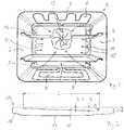
- Fig. 2 shows the top view of a baffle 14 of the cooking appliance 1 according to the invention in the installed position.
- the baffle 14 has a baffle 14 frame-shaped surrounding air duct 16 which projects at right angles from the plane of the baffle 14.
- the baffle 14 forms together with the Heilleitabrough 16 a trough-shaped structure, at the edges of the exhaust openings 15 are arranged.
- the exhaust openings 15 at the upper, horizontally extending air guide section 16.
- the exhaust opening 15 has a 3-sided geometry. This geometry defines the cross section and thus the air passage of the exhaust opening 15.
- the exhaust opening 15 has a length (L) and a depth (T).
- Fig. 3 shows the same baffle 14 in four different perspective views, respectively, to illustrate the shape and the arrangement of the exhaust openings 15.
- the exemplary embodiment are located on the baffle 14 in total four exhaust ports 15, wherein one of the two vertical edges of the Heilleitabitess 16 and one each at the upper and lower, horizontally extending portions of the Heilleitabitess 16 is arranged.
- the exact arrangement of the exhaust openings 14 depends on the circumstances of the cooking chamber 1, wherein the goal is to achieve within the cooking chamber 1, a best possible uniform heat distribution for optimum cooking result.
- the cross section of the outlet opening 15 becomes adapted, for example by a greater degree of depth (T), that the resistance is compensated.
- the blow-out openings 15 on the air-guiding section 16 are arranged mirror-symmetrically with respect to the horizontally and vertically extending center axes of the intake opening 13.
- Fig. 4 shows in an embodiment, the top view of a blow-out opening 15, which has the geometry of a right triangle.
- the length (L) and the depth (T) define the dimensions of the triangle.
- Fig. 5 shows in an embodiment, the top view of a blow-out opening 15, which has the geometry of a stepped recess.
- the length (L) and the depth (T) define the dimensions of the recess.
- Fig. 6 shows in an embodiment, the top view of a blow-out opening 15, which has a composite geometric shape. This is formed by a rectangular base surface 17 and a 3-cornered connection surface. The length (L) and the depth (T) define the dimensions of the recess.
- Fig. 7 shows in an embodiment, the top view of a blow-out opening 15 which has the geometry of a free-form, in which the edge is not linear. Accordingly, the edges of the exhaust opening 15 are not limited to straight edges.
- the length (L) and the depth (T) define the dimensions of the recess.
- Fig. 8 shows in one embodiment, the top view of a blow-out opening 15, with another geometry of a free form with a non-linear edge.
- the length (L) and the depth (T) define the dimensions of the recess.
Landscapes
- Engineering & Computer Science (AREA)
- Chemical & Material Sciences (AREA)
- Combustion & Propulsion (AREA)
- Mechanical Engineering (AREA)
- General Engineering & Computer Science (AREA)
- Baking, Grill, Roasting (AREA)
Abstract
Description
- Die vorliegende Erfindung betrifft ein Gargerät mit einem verschließbaren Garraum, in dem zwischen einer Garraumwand und einer Prallwand eine Gebläsekammer gebildet ist, in der ein Gebläserad angeordnet ist und Luft durch mindestens eine Ansaugöffnung der Prallwand in die Gebläsekammer saugt und durch zumindest eine Ausblasöffnung der Prallwand aus der Gebläsekammer ausbläst.
- Derartige Gargeräte sind beispielsweise aus der
DE 2557867 A1 bekannt, wobei die Ausblasöffnung in den beiden Seitenbereichen der Prallwand jeweils durch zwei langgestreckte vertikale Ausblasschlitze gebildet ist. Um eine Vergleichmäßigung der Luftströmung und der Wärmeverteilung im Garraum zu erzielen, ist das Gebläse von Luftleitblechen umgeben, die die im Wesentlichen radial vom Gebläse wegströmende Luft horizontal auf die Ausblasschlitze zuleiten. Diese langgestreckten Ausblasschlitze erzeugen durch ihre in Längsrichtung gleichbleibende Geometrie eine gleichbleibende Luftströmung. - Moderne Gargeräte, mit hohen Anforderungen an die Wärmeverteilung, erfordern eine individuelle, auf die Gegebenheiten des Garraums angepasste Luftströmung.
- Aufgabe der vorliegenden Erfindung ist es, ein Gargerät bereitzustellen, das mit einfachen Mitteln eine gezielte Luftströmung ermöglicht, um eine gleichmäßige Wärmeverteilung im Garraum zu erreichen.
- Die Erfindung geht aus von einem Gargerät, insbesondere Backofen, mit einem verschließbaren Garraum, in dem zwischen einer Garraumwand und einer Prallwand eine Gebläsekammer gebildet ist, in der ein Gebläserad angeordnet ist und Luft durch mindestens eine Ansaugöffnung der Prallwand in die Gebläsekammer saugt und durch zumindest eine Ausblasöffnung der Prallwand aus der Gebläsekammer ausbläst. Unter einem Garraum soll insbesondere der durch drei Seitenwände sowie Boden und Decke begrenzte Raum verstanden werden, der frontseitig mit einer Tür verschließbar ist. Dabei teilt sich der Garraum in zwei Bereiche auf. Der dem Nutzer zugewandte Bereich, in dem Gargutträger, wie z.B. Backbleche oder Roste, einschiebbar sind, dient als Behandlungsraum für das Gargut. Vorzugsweise im hinteren Bereich des Garraums befindet sich die, durch eine Prallwand abgegrenzte Gebläsekammer, welche dazu eingerichtet ist, durch eine zentrale Ansaugöffnung in der Prallwand Luft aus dem Behandlungsraum mittels eines Gebläserads anzusaugen und durch zumindest eine Ausblasöffnung in der Prallwand erneut in den Behandlungsraum einzublasen.
- Erfindungsgemäß wird die Aufgabe dadurch gelöst, dass zumindest eine Ausblasöffnung eine Länge (L) und eine Tiefe (T) aufweist und die Tiefe (T) über den Verlauf der Länge (L) ein variierendes Maß aufweist. Unter einer Ausblasöffnung soll insbesondere ein Durchlass in der Gebläsekammer verstanden werden, welche geeignet ist, zumindest eine Teilmenge des angesaugten Luftstroms in den Behandlungsraum zu leiten. Eine derartige Ausblasöffnung kann durch eine Aussparung oder Ausstanzung aus dem Blech der Prallwand gebildet sein, wobei diese Ausblasöffnung vorzugsweise im Randbereich der Prallwand angeordnet ist und wahlweise zum Rand einen oder keinen verbleibenden Steg aufweist. Unter der Länge (L) soll insbesondere die Erstreckung der Ausblasöffnung verstanden werden. Unter der Tiefe (T) soll insbesondere die Breite der Ausblasöffnung, vorzugsweise rechtwinklig gesehen zur Länge (L) verstanden werden. Unter dem variierenden Maß der Tiefe (T) soll insbesondere verstanden werden, dass die Geometrie der Ausblasöffnung über den Verlauf der Länge (L) sich derart verändert, dass sich der Querschnitt der Ausblasöffnung über den Verlauf der Länge (L) verändert. Bedarf eine Stelle im Garraum mehr Luftvolumen, so wird an der zugehörigen Stelle an der Ausblasöffnung mehr Luftdurchsatz mittels höherem Querschnitt, durch ein größeres Maß der Tiefe (T) erzielt. Ist eine Verringerung des Luftdurchsatzes an einer Stelle im Garraum gewünscht, wird an der zugehörigen Stelle der Ausblasöffnung der Luftdurchsatz mittels geringerem Querschnitt, durch ein kleineres Maß der Tiefe (T) erzielt. Befindet sich beispielsweise an der Seitenwand ein Gegenstand, z.B. eine den Garraum beleuchtende Garraumlampe, welche in die Luftströmung ragt und somit einen Widerstand für die Luftströmung bildet, so wird der Querschnitt der Ausblasöffnung derart angepasst, z.B. durch ein größeres Maß der Tiefe (T), dass der Widerstand ausgeglichen wird. Eine erfindungsgemäße Ausblasöffnung kann somit regelmäßige (gerade) Kanten oder unregelmäßige (z.B. stufen- oder wellenförmige) Kanten aufweisen. Durch diese individuelle Anpassung des Querschnitts der Ausblasöffnung lässt sich die Luftströmung individuelle auf die Gegebenheiten des Garraums anpassen, wodurch eine ideale Wärmeverteilung erzielt wird. Zudem kann auf zusätzliche Luftleitbleche verzichtet werden.
- Vorzugsweise ist die zumindest eine Ausblasöffnung zu jeder, in Erstreckungsrichtung der Prallwand gesehen, senkrechten- oder parallelen Linie, insbesondere Symmetrielinie asymmetrisch. Unter einer asymmetrischen Ausblasöffnung sollen insbesondere Querschnitte verstanden werden, welche eine eckige, stufenförmige oder wellenförmige Kontur aufweisen. Eine asymmetrische Geometrie der Ausblasöffnung kann durch ihren in Längsrichtung ungleichmäßigen Querschnitt eine besonders gute Luftströmung erzeugen.
- Vorzugsweise weist die zumindest eine Ausblasöffnung eine dreieckige Geometrie auf. Unter einer dreieckigen Geometrie soll insbesondere eine geometrische Figur verstanden werden, welche drei Ecken aufweist. Die Scheitel der Dreiecke können als Eckpunkte ausgeführt sein oder als geometrische bzw. theoretische Eckpunkte dienen, wobei die körperliche Ausbildung der Ausblasöffnung am Scheitelpunkt nicht eckig ist. In diesem Fall bezieht sich die dreieckige Geometrie auf die wesentliche Kontur des Polygonzugs. Durch eine dreieckige Geometrie ist eine gleichmäßige Anpassung der Luftströmung über den Querschnitt möglich, da der Querschnitt stetig bzw. linear zu- oder abnimmt. Dabei ist das Luftvolumen an Stellen mit einem kleinen Maß der Tiefe (T) geringer und an Stellen mit einem großen Maß der Tiefe (T) höher.
- Vorzugsweise weist die Ausblasöffnung im Wesentlichen die Geometrie eines rechtwinkligen Dreiecks auf. Unter einem rechtwinkligen Dreieck soll insbesondere ein Dreieck verstanden werden, das einen 90°-Winkel, also einen rechten Winkel aufweist. Die dem rechten Winkel gegenüberliegende Seite ist die längste Seite des Dreiecks und wird Hypotenuse genannt. Eine Ausbildung sieht vor, dass die Hypotenuse den Rand der Prallwand bzw. des Luftleitabschnitts bildet oder im Wesentlichen parallel zu diesem angeordnet ist, so dass ein Rand verbleibt. Alternativ ist die Hypotenuse der Ansaugöffnung der Prallwand zugewandt.
- Gemäß einer Variante weist die Ausblasöffnung im Wesentlichen die Geometrie eines gleichschenkligen oder gleichseitigen Dreiecks auf. Unter einem gleichschenkligen Dreieck soll insbesondere ein Dreieck verstanden werden, bei dem mindestens zwei Seiten gleich lang sind. Diese Seiten werden als Schenkel bezeichnet, die dritte Seite heißt Basis des gleichschenkligen Dreiecks. Eine Ausbildung sieht vor, dass die Basis den Rand der Prallwand bzw. des Luftleitabschnitts bildet oder im Wesentlichen parallel zu diesem angeordnet ist, so dass ein Rand verbleibt. Alternativ ist die Basis der Ansaugöffnung der Prallwand zugewandt. Unter einem gleichseitigen Dreieck soll insbesondere ein Dreieck verstanden werden, bei dem alle drei Seiten gleich lang sind.
- Gemäß einer weiteren Variante weist die Ausblasöffnung eine zusammengesetzte geometrische Form, umfassend eine rechteckige Basisfläche und eine Anschlussfläche auf, wobei das Maß der Tiefe (T) über den Verlauf der Länge (L) ein variierenden Maß aufweist. Unter einer rechteckigen Basisfläche soll insbesondere ein rechteckiger Querschnitt verstanden werden, der für einen höheren Luftdurchsatz der Ausblasöffnung sorgt. Im Bereich einer Ecke oder Spitze, z.B. bei einem Dreieck, an dem der Luftdurchsatz aufgrund des geringen Maßes der Tiefe (T) gegen Null strebt, ist die Basisfläche von besonderem Vorteil, da mit dieser ein Mindestluftdurchsatz sichergestellt ist.
- Vorzugsweise weist die Geometrie der Ausblasöffnung eine 3 oder 4+n eckige Grundfläche auf. Unter einer Ausblasöffnung mit einer 3-eckigen Grundfläche sollen insbesondere alle voran beschriebenen dreieckigen Geometrien verstanden werden. Unter einer Ausblasöffnung mit einer 4+n eckigen Grundfläche sollen alle Geometrie verstanden werden, welche mehr als vier, z.B. 5, 6, 7 ..., Ecken aufweisen. Somit lassen sich vorteilhafter Weise alle Ausblasöffnungen mit vieleckigen, polygonalen Querschnitten mit 3 oder 4+n eckigen Querschnitten abbilden.
- Vorzugsweise weisen die Ecken der Ausblasöffnung einen Radius oder eine Phase auf. Unter einem Radius soll insbesondere ein Teil einer Kreisumfangsfläche verstanden werden, welcher einem Winkel die Spitze nimmt. Dies ist besonders von Vorteil, um scharfkantige Ecken und somit Verletzungen zu vermeiden oder eine ausreichend gute Emaillierung sicher zu stellen und eine homogenere Strömung an den Ecken zu gewährleisten. Alternativ kann die Ecke der Ausblasöffnung auch über eine Abschrägung in Form einer Fase entschärft werden. Es wird darauf hingewiesen, dass der Radius oder die Fase an der oder den Ecken keinen Einfluss auf die geometrische Form der erfindungsgemäßen Ausblasöffnung haben.
- Vorzugsweise beträgt die Länge (L) zwischen 1 cm und 50 cm, vorzugsweise zwischen 2 cm und 30 cm, insbesondere 2,5 cm, 21,5 cm oder 24 cm.
- Bitte vorzugsweise beträgt die maximale Tiefe (T) zwischen 0,1 cm und 5 cm, vorzugsweise zwischen 0,2 cm und 3 cm, insbesondere 1 cm.
- Vorzugsweise weist die Prallwand zwischen 1 und 8, vorzugsweise 2 bis 6 und insbesondere 4 Ausblasöffnungen auf.
- Vorzugsweise sind gegenüberliegende Ausblasöffnungen spiegelsymmetrisch angeordnet oder verdreht, insbesondere Punktsymetrisch zueinander angeordnet. Durch diese symmetrisch angeordneten Ausblasöffnungen entsteht eine besonders gute Verteilung der Warmluft über alle Einschubebenen des Gargeräts, was eine besonders gute Bräunungsverteilung erzielt.
- Vorzugsweise weist die Prallwand einen im Wesentlichen rechtwinklig angeordneten Luftleitabschnitt auf, der einen rahmenartigen Rand der Prallwand bildet und wobei auf dem Luftleitabschnitt die zumindest eine Ausblasöffnung angeordnet ist. Unter einem Luftleitabschnitt soll insbesondere ein die Prallwand ergänzender Abschnitt verstanden werden, der die Prallwand vorzugsweise rahmenförmig umgibt. Dieser Luftleitabschnitt formt aus dem im Wesentlichen flachen Gebilde der Prallwand ein wannenförmiges Gebilde, wobei die Öffnung dieser Gebläsekammer dem Gebläserad zugewandt ist. Vorteilhaft an dieser Ausgestaltung ist, dass die auf den Luftleitabschnitten angeordneten Ausblasöffnungen den Luftstrom zunächst im Wesentlichen parallel zur Rückwand des Garraums aus der Gebläsekammer blasen, und die Seitenwände als einen den Luftstrom reflektierende Diffusor nutzen, um eine größtmögliche Verteilung der Wärme durch Verwirbelung zu erzeugen.
- Vorzugsweise ist das Luftleitelement einstückig aus der Prallwand gebildet, wodurch eine besonders einfache Herstellung der Prallwand mit Luftleitabschnitten, insbesondere durch ein Tiefziehverfahren möglich ist. Gemäß einer Alternative sind die Luftleitelemente mit Ausblasöffnungen aus einem eigenständigen Bauteil und bilden zusammen mit der Prallwand eine gemeinsame Gebläsekammer.
- Weitere Merkmale der Erfindung ergeben sich aus den Figuren und der Figurenbeschreibung. Die vorstehend in der Beschreibung genannten Merkmale und Merkmalsdefinitionen sowie die nachfolgend in der Figurenbeschreibung genannten und/oder in den Figuren alleine gezeigten Merkmale und Merkmalskombinationen sind nicht nur in der jeweils angegebenen Kombination, sondern auch in anderen Kombinationen oder in Alleinstellung verwendbar, ohne den Rahmen der Erfindung zu verlassen. Es sind auch Ausführungsbeispiele von der Erfindung als umfasst und offenbart anzusehen, die in den schematischen Figuren nicht explizit gezeigt und erläutert sind, jedoch durch separierte Merkmalskombinationen aus den erläuterten Ausführungen hervorgehen und erzeugbar sind. Dabei zeigt:
-
Fig. 1 eine schematische perspektivische Darstellung eines Garraums eines erfindungsgemäßen Gargeräts; -
Fig. 2 eine Draufsicht auf eine die Gebläsekammer bildende Prallwand; -
Fig. 3 vier perspektivische Ansichten auf eine die Gebläsekammer bildende Prallwand; und -
Fig. 4 - 8 Draufsichten auf mögliche Ausgestaltungen der Geometrien der Ausblasöffnungen. - Gleiche oder funktionsgleiche Elemente werden in den Figuren mit den gleichen Bezugszeichen versehen.
- In
Fig. 1 ist in einer perspektivischen Darstellung ein Garraum 1 eines erfindungsgemäßen Gargeräts zum Zubereiten von Lebensmitteln gezeigt, welches im Ausführungsbeispiel ein Backofen ist. Der Garraum 1 ist durch die Seitenwände 2, 3 des Backrohrs begrenzt. Frontseitig weist der Garraum 1 eine Beschickungsöffnung auf, die durch eine nicht dargestellte Tür verschließbar ist. An den Seitenwänden 2, 3 befinden sich Seitengitter 4, die das Zubehör 5, wie z. B. Roste, Backbleche oder ähnliches Zubehör auf unterschiedlichen Einschubhöhen aufnehmen. Der Garraum 1 weist eine Decke 6 auf, an der ein Oberhitze Heizkörper 7 angeordnet ist. Zudem weist der Garraum 1 einen Boden 8 auf, unter dem ein Unterhitze Heizkörper 9 angeordnet ist. An der Rückwand 10 des Garraums 1 ist eine Gebläsekammer 11 angeordnet, in der ein Gebläserad 12 die durch die Ober- bzw. Unterhitze Heizkörper 7, 9 aufgewärmte Luft durch mindestens eine, inFig. 1 ausgesparte, Ansaugöffnung 13 der Prallwand 14 in die Gebläsekammer 11 saugt und durch zumindest eine Ausblasöffnung 15 der Prallwand 14 aus der Gebläsekammer 11 ausbläst. -
Fig. 2 zeigt die Draufsicht auf eine Prallwand 14 des erfindungsgemäßen Gargeräts 1 in Einbaulage. Die Prallwand 14 weist einen die Prallwand 14 rahmenförmig umgebenden Luftleitabschnitt 16 auf, der rechtwinklig von der Ebene der Prallwand 14 absteht. Somit bildet die Prallwand 14 zusammen mit dem Luftleitabschnitt 16 ein wannenförmiges Gebilde, an dessen Rändern die Ausblasöffnungen 15 angeordnet sind. Im Ausführungsbeispiel nachFigur 2 sieht man die Ausblasöffnungen 15 am oberen, waagerecht verlaufenden Luftleitabschnitt 16. Die Ausblasöffnung 15 weist eine 3-eckige Geometrie auf. Diese Geometrie definiert den Querschnitt und somit den Luftdurchlass der Ausblasöffnung 15. Die Ausblasöffnung 15 weist eine Länge (L) und eine Tiefe (T) auf. Über die Länge (L) variiert das Maß der Tiefe (T) in der Art, dass im Ausführungsbeispiel bei einer 3-eckigen Geometrie der Ausblasöffnung 15 das Maß T1 größer ist als das Maß T2. Bei dem gezeigten Dreieck handelt es sich um ein rechtwinkliges Dreieck, dessen Ankathete am freien Ende bis Luftleitabschnitts 16 angeordnet ist und Länge (L) definiert. Die Gegenkathete stellt das maximale Maß der Tiefe (T) dar. Durch Radien R an den Spitzen des Dreiecks werden scharfkantige Ecken vermieden. -
Fig. 3 zeigt die gleiche Prallwand 14 in jeweils vier unterschiedlichen perspektivischen Ansichten, um die Form und die Anordnung der Ausblasöffnungen 15 zu verdeutlichen. Im Ausführungsbeispiel befinden sich an der Prallwand 14 in Summe vier Ausblasöffnungen 15, wobei jeweils eine an den beiden senkrechten Flanken des Luftleitabschnitts 16 sowie je eine an den oberen und unteren, waagerecht verlaufenden Bereichen des Luftleitabschnitts 16 angeordnet ist. Die genaue Anordnung der Ausblasöffnungen 14 richtet sich nach den Gegebenheiten des Garraums 1, wobei das Ziel ist, innerhalb des Garraums 1 eine bestmögliche, gleichmäßige Wärmeverteilung für ein optimales Garergebnis zu erzielen. Befindet sich beispielsweise an der Seitenwand 2, 3 ein Gegenstand, z.B. eine den Garraum 1 beleuchtende Garraumlampe, welche einen Widerstand für die Luftströmung darstellt, so wird der Querschnitt der Ausblasöffnung 15 derart angepasst, z.B. durch ein größeres Maß der Tiefe (T), dass der Widerstand ausgeglichen wird. Die Ausblasöffnungen 15 am Luftleitabschnitt 16 sind spiegelsymmetrisch zu den waagrecht und senkrecht verlaufenden Mittelpunktsachsen der Ansaugöffnung 13 angeordnet. -
Fig. 4 zeigt in einem Ausführungsbeispiel die Draufsicht auf eine Ausblasöffnung 15, welche die Geometrie eines rechtwinkligen Dreiecks aufweist. Die Länge (L) und die Tiefe (T) definieren die Abmaße des Dreiecks. -
Fig. 5 zeigt in einem Ausführungsbeispiel die Draufsicht auf eine Ausblasöffnung 15, welche die Geometrie einer stufenförmigen Aussparung aufweist. Die Länge (L) und die Tiefe (T) definieren die Abmaße der Aussparung. -
Fig. 6 zeigt in einem Ausführungsbeispiel die Draufsicht auf eine Ausblasöffnung 15, welche eine zusammengesetzte geometrische Form aufweist. Diese wird gebildet durch eine rechteckige Basisfläche 17 und eine 3-eckige Anschlussfläche. Die Länge (L) und die Tiefe (T) definieren die Abmaße der Aussparung. -
Fig. 7 zeigt in einem Ausführungsbeispiel die Draufsicht auf eine Ausblasöffnung 15, welche die Geometrie einer Freiform aufweist, bei der die Kante nicht linear ist. Demnach sind die Kanten der Ausblasöffnung 15 nicht auf gerade Kanten beschränkt. Die Länge (L) und die Tiefe (T) definieren die Abmaße der Aussparung. -
Fig. 8 zeigt in einem Ausführungsbeispiel die Draufsicht auf eine Ausblasöffnung 15, mit einer weiteren Geometrie einer Freiform mit einer nicht linearen Kante. Die Länge (L) und die Tiefe (T) definieren die Abmaße der Aussparung. - Für den Fachmann ist erkennbar, dass die Erfindung nicht auf die dargestellten Ausführungsbeispiele beschränkt ist, sondern dass eine Vielzahl von Varianten und Abwandlungen ebenfalls davon umfasst sind.
-
- 1
- Garraum
- 2
- erste Seitenwand
- 3
- zweite Seitenwand
- 4
- Seitengitter
- 5
- Zubehör
- 6
- Decke
- 7
- Unterhitze Heizkörper
- 8
- Boden
- 9
- Oberhitze Heizkörper
- 10
- Rückwand
- 11
- Gebläsekammer
- 12
- Gebläserad
- 13
- Ansaugöffnung
- 14
- Prallwand
- 15
- Ausblasöffnung
- 16
- Luftleitabschnitt
- 17
- Basisfläche
- R
- Radius
- L
- Länge der Ausblasöffnung
- T
- Tiefe der Ausblasöffnung
Claims (14)
- Gargerät, insbesondere Backofen, mit einem verschließbaren Garraum (1), in dem zwischen einer Garraumwand (2, 3) und einer Prallwand eine Gebläsekammer (11) gebildet ist, in der ein Gebläserad (12) angeordnet ist und Luft durch mindestens eine Ansaugöffnung (13) der Prallwand (14) in die Gebläsekammer (11) saugt und durch zumindest eine Ausblasöffnung (15) der Prallwand (14) aus der Gebläsekammer (11) ausbläst, dadurch gekennzeichnet, dass die zumindest eine Ausblasöffnung (15) eine Länge (L) und eine Tiefe (T) aufweist und die Tiefe (T) über den Verlauf der Länge (L) ein variierendes Maß aufweist.
- Gargerät nach Anspruch 1, dadurch gekennzeichnet, dass die zumindest eine Ausblasöffnung (15) asymmetrisch zu jeder, in Erstreckungsrichtung der Prallwand gesehen, senkrechten- oder parallelen Linie ist.
- Gargerät nach Anspruch 1 oder 2, dadurch gekennzeichnet, dass zumindest eine Ausblasöffnung (15) eine dreieckige Geometrie aufweist.
- Gargerät nach einem der vorangegangenen Ansprüche, dadurch gekennzeichnet, dass die Ausblasöffnung (15) im Wesentlichen die Geometrie eines rechtwinkligen Dreiecks aufweist.
- Gargerät nach Anspruch 1 oder 3, dadurch gekennzeichnet, dass die Ausblasöffnung (15) im Wesentlichen die Geometrie eines gleichschenkligen oder gleichseitigen Dreiecks aufweist.
- Gargerät nach einem der vorangegangenen Ansprüche, dadurch gekennzeichnet, dass die Ausblasöffnung (15) eine zusammengesetzte geometrische Form aufweist, umfassend eine rechteckige Basisfläche (17) und eine Anschlussfläche, die eine Tiefe (T) mit über den Verlauf der Länge (L) ein variierendem Maß aufweist.
- Gargerät nach einem der vorangegangenen Ansprüche, dadurch gekennzeichnet, dass die Geometrie der Ausblasöffnung (15) eine 3 oder 4+n eckige Grundfläche aufweist.
- Gargerät nach einem der vorangegangenen Ansprüche, dadurch gekennzeichnet, dass zumindest eine Ecke der Ausblasöffnung (15) einen Radius (R) oder eine Fase aufweist.
- Gargerät nach einem der vorangegangenen Ansprüche, dadurch gekennzeichnet, dass die Länge (L) zwischen 1cm und 50 cm, vorzugsweise zwischen 2 cm und 30 cm, insbesondere 2,5 cm, 21,5 cm oder 24 cm beträgt.
- Gargerät nach einem der vorangegangenen Ansprüche, dadurch gekennzeichnet, dass die maximale Tiefe (T) zwischen 0,1cm und 5 cm, vorzugsweise zwischen 0,2 cm und 3 cm, insbesondere 1 cm beträgt.
- Gargerät nach einem der vorangegangenen Ansprüche, dadurch gekennzeichnet, dass die Prallwand (14) zwischen 1 und 8, vorzugsweise 2 bis 6 und insbesondere 4 Ausblasöffnungen (15) aufweist.
- Gargerät nach einem der vorangegangenen Ansprüche, dadurch gekennzeichnet, dass gegenüberliegende Ausblasöffnungen (15) spiegelsymmetrisch oder verdreht, insbesondere Punktsymmetrisch zueinander angeordnet sind.
- Gargerät nach einem der vorangegangenen Ansprüche, dadurch gekennzeichnet, dass die Prallwand (14) einen im Wesentlichen rechtwinklig angeordneten Luftleitabschnitt (16) aufweist, der einen rahmenartigen Rand der Prallwand bildet und wobei auf dem Luftleitabschnitt (16) die zumindest eine Ausblasöffnung (15) angeordnet ist.
- Gargerät nach einem der vorangegangenen Ansprüche, dadurch gekennzeichnet, dass der Luftleitabschnitt (16) einstückig aus der Prallwand (14) gebildet ist oder aus einem separaten Bauteil gebildet ist.
Applications Claiming Priority (1)
| Application Number | Priority Date | Filing Date | Title |
|---|---|---|---|
| DE102017202733.9A DE102017202733A1 (de) | 2017-02-21 | 2017-02-21 | Gargerät mit einer Ausblasöffnung |
Publications (2)
| Publication Number | Publication Date |
|---|---|
| EP3364113A1 true EP3364113A1 (de) | 2018-08-22 |
| EP3364113B1 EP3364113B1 (de) | 2021-08-04 |
Family
ID=60997370
Family Applications (1)
| Application Number | Title | Priority Date | Filing Date |
|---|---|---|---|
| EP18151881.2A Active EP3364113B1 (de) | 2017-02-21 | 2018-01-16 | Gargerät mit einer ausblasöffnung |
Country Status (2)
| Country | Link |
|---|---|
| EP (1) | EP3364113B1 (de) |
| DE (1) | DE102017202733A1 (de) |
Cited By (2)
| Publication number | Priority date | Publication date | Assignee | Title |
|---|---|---|---|---|
| EP4248140A1 (de) * | 2020-11-20 | 2023-09-27 | BSH Hausgeräte GmbH | Gargerät mit heissluftsystem und spezifisch geformten garraumteiler im bereich einer frontwand des heissluftsystems |
| EP4403833A1 (de) * | 2023-01-20 | 2024-07-24 | MIWE Michael Wenz GmbH | Behandlungsgerät mit einer trennwand zur behandlung von lebensmitteln |
Citations (4)
| Publication number | Priority date | Publication date | Assignee | Title |
|---|---|---|---|---|
| DE2557867A1 (de) | 1975-12-22 | 1977-06-30 | Bosch Siemens Hausgeraete | Umluftofen |
| EP1467154A2 (de) * | 2003-04-10 | 2004-10-13 | Samsung Electronics Co., Ltd. | Gargerät |
| US20080017348A1 (en) * | 2005-01-25 | 2008-01-24 | Lance Criscuolo | Apparatus for thawing frozen food items |
| WO2016016780A1 (en) * | 2014-07-29 | 2016-02-04 | Ma.Ti.Ka. S.R.L. | Panel for ovens |
Family Cites Families (1)
| Publication number | Priority date | Publication date | Assignee | Title |
|---|---|---|---|---|
| KR101713402B1 (ko) * | 2015-03-06 | 2017-03-07 | 엘지전자 주식회사 | 조리기기 |
-
2017
- 2017-02-21 DE DE102017202733.9A patent/DE102017202733A1/de not_active Withdrawn
-
2018
- 2018-01-16 EP EP18151881.2A patent/EP3364113B1/de active Active
Patent Citations (4)
| Publication number | Priority date | Publication date | Assignee | Title |
|---|---|---|---|---|
| DE2557867A1 (de) | 1975-12-22 | 1977-06-30 | Bosch Siemens Hausgeraete | Umluftofen |
| EP1467154A2 (de) * | 2003-04-10 | 2004-10-13 | Samsung Electronics Co., Ltd. | Gargerät |
| US20080017348A1 (en) * | 2005-01-25 | 2008-01-24 | Lance Criscuolo | Apparatus for thawing frozen food items |
| WO2016016780A1 (en) * | 2014-07-29 | 2016-02-04 | Ma.Ti.Ka. S.R.L. | Panel for ovens |
Cited By (3)
| Publication number | Priority date | Publication date | Assignee | Title |
|---|---|---|---|---|
| EP4248140A1 (de) * | 2020-11-20 | 2023-09-27 | BSH Hausgeräte GmbH | Gargerät mit heissluftsystem und spezifisch geformten garraumteiler im bereich einer frontwand des heissluftsystems |
| EP4248140B1 (de) * | 2020-11-20 | 2026-01-07 | BSH Hausgeräte GmbH | Gargerät mit heissluftsystem und spezifisch geformten garraumteiler im bereich einer frontwand des heissluftsystems |
| EP4403833A1 (de) * | 2023-01-20 | 2024-07-24 | MIWE Michael Wenz GmbH | Behandlungsgerät mit einer trennwand zur behandlung von lebensmitteln |
Also Published As
| Publication number | Publication date |
|---|---|
| EP3364113B1 (de) | 2021-08-04 |
| DE102017202733A1 (de) | 2018-08-23 |
Similar Documents
| Publication | Publication Date | Title |
|---|---|---|
| DE69824826T2 (de) | Ansaugknie mit eingebauten Leitflügeln | |
| DE3306972C2 (de) | Gerät zur Wärmebehandlung von Lebensmitteln und Speisen | |
| DE102012003336A1 (de) | Diffusor, Ventilator mit einem solchen Diffusor sowie Gerät mit solchen Ventilatoren | |
| DE2557867A1 (de) | Umluftofen | |
| DE2830342A1 (de) | Eingebauter doppelbackofen | |
| EP0833110B1 (de) | Backofen mit Gebläse | |
| EP1970635A2 (de) | Heissluft-Backofen mit Umlenkblechen | |
| EP2333348A2 (de) | Radiallüftergehäuse | |
| EP3364113B1 (de) | Gargerät mit einer ausblasöffnung | |
| DE102010062147A1 (de) | Hausgerät mit einem Außengehäuse, welches eine Seitenwand aufweist und einen Luftführungskanal umfasst | |
| DE3633236C2 (de) | ||
| EP3869106A1 (de) | Kochfeld mit kochstelle und absaugvorrichtung für kochdünste | |
| DE212013000156U1 (de) | Vorrichtungen zum Beruhigen eines Luftstroms | |
| EP3035032B1 (de) | Simulationsschrank | |
| DE212013000201U1 (de) | Heißluft-Etagenofen | |
| EP2716990B1 (de) | Decken- oder Wandgerät zum Einbringen gekühlter oder erwärmter Luft in einen Raum | |
| EP2626644A1 (de) | Lüftungsbauteil, umfassend ein kanalförmiges Gehäuse mit umlaufend angeordneten Gehäusewandungen | |
| DE102010037557A1 (de) | Ablauf für einen Abgaskanal | |
| EP3285017A1 (de) | Heiz- und kühlsegel mit mindestens einem ventilator | |
| DE202008010063U1 (de) | Lufttechnische Einrichtung | |
| EP2072902A1 (de) | Heißluft- oder Umluftofen | |
| WO2008148675A2 (de) | Backofen | |
| DE19721334C2 (de) | Kühlbahn, insbesondere zum Kühlen von Glasgegenständen | |
| DE2125342A1 (de) | Gasbackofen | |
| DE102007027640A1 (de) | Gargerätegebläsevorrichtungseinheit |
Legal Events
| Date | Code | Title | Description |
|---|---|---|---|
| PUAI | Public reference made under article 153(3) epc to a published international application that has entered the european phase |
Free format text: ORIGINAL CODE: 0009012 |
|
| STAA | Information on the status of an ep patent application or granted ep patent |
Free format text: STATUS: THE APPLICATION HAS BEEN PUBLISHED |
|
| AK | Designated contracting states |
Kind code of ref document: A1 Designated state(s): AL AT BE BG CH CY CZ DE DK EE ES FI FR GB GR HR HU IE IS IT LI LT LU LV MC MK MT NL NO PL PT RO RS SE SI SK SM TR |
|
| AX | Request for extension of the european patent |
Extension state: BA ME |
|
| STAA | Information on the status of an ep patent application or granted ep patent |
Free format text: STATUS: REQUEST FOR EXAMINATION WAS MADE |
|
| 17P | Request for examination filed |
Effective date: 20190222 |
|
| RBV | Designated contracting states (corrected) |
Designated state(s): AL AT BE BG CH CY CZ DE DK EE ES FI FR GB GR HR HU IE IS IT LI LT LU LV MC MK MT NL NO PL PT RO RS SE SI SK SM TR |
|
| STAA | Information on the status of an ep patent application or granted ep patent |
Free format text: STATUS: EXAMINATION IS IN PROGRESS |
|
| 17Q | First examination report despatched |
Effective date: 20200714 |
|
| GRAP | Despatch of communication of intention to grant a patent |
Free format text: ORIGINAL CODE: EPIDOSNIGR1 |
|
| STAA | Information on the status of an ep patent application or granted ep patent |
Free format text: STATUS: GRANT OF PATENT IS INTENDED |
|
| INTG | Intention to grant announced |
Effective date: 20210329 |
|
| GRAS | Grant fee paid |
Free format text: ORIGINAL CODE: EPIDOSNIGR3 |
|
| GRAA | (expected) grant |
Free format text: ORIGINAL CODE: 0009210 |
|
| STAA | Information on the status of an ep patent application or granted ep patent |
Free format text: STATUS: THE PATENT HAS BEEN GRANTED |
|
| AK | Designated contracting states |
Kind code of ref document: B1 Designated state(s): AL AT BE BG CH CY CZ DE DK EE ES FI FR GB GR HR HU IE IS IT LI LT LU LV MC MK MT NL NO PL PT RO RS SE SI SK SM TR |
|
| REG | Reference to a national code |
Ref country code: GB Ref legal event code: FG4D Free format text: NOT ENGLISH |
|
| REG | Reference to a national code |
Ref country code: AT Ref legal event code: REF Ref document number: 1417356 Country of ref document: AT Kind code of ref document: T Effective date: 20210815 |
|
| REG | Reference to a national code |
Ref country code: CH Ref legal event code: EP |
|
| REG | Reference to a national code |
Ref country code: DE Ref legal event code: R096 Ref document number: 502018006381 Country of ref document: DE |
|
| REG | Reference to a national code |
Ref country code: IE Ref legal event code: FG4D Free format text: LANGUAGE OF EP DOCUMENT: GERMAN |
|
| REG | Reference to a national code |
Ref country code: LT Ref legal event code: MG9D |
|
| REG | Reference to a national code |
Ref country code: NL Ref legal event code: MP Effective date: 20210804 |
|
| PG25 | Lapsed in a contracting state [announced via postgrant information from national office to epo] |
Ref country code: BG Free format text: LAPSE BECAUSE OF FAILURE TO SUBMIT A TRANSLATION OF THE DESCRIPTION OR TO PAY THE FEE WITHIN THE PRESCRIBED TIME-LIMIT Effective date: 20211104 Ref country code: LT Free format text: LAPSE BECAUSE OF FAILURE TO SUBMIT A TRANSLATION OF THE DESCRIPTION OR TO PAY THE FEE WITHIN THE PRESCRIBED TIME-LIMIT Effective date: 20210804 Ref country code: NO Free format text: LAPSE BECAUSE OF FAILURE TO SUBMIT A TRANSLATION OF THE DESCRIPTION OR TO PAY THE FEE WITHIN THE PRESCRIBED TIME-LIMIT Effective date: 20211104 Ref country code: PT Free format text: LAPSE BECAUSE OF FAILURE TO SUBMIT A TRANSLATION OF THE DESCRIPTION OR TO PAY THE FEE WITHIN THE PRESCRIBED TIME-LIMIT Effective date: 20211206 Ref country code: RS Free format text: LAPSE BECAUSE OF FAILURE TO SUBMIT A TRANSLATION OF THE DESCRIPTION OR TO PAY THE FEE WITHIN THE PRESCRIBED TIME-LIMIT Effective date: 20210804 Ref country code: SE Free format text: LAPSE BECAUSE OF FAILURE TO SUBMIT A TRANSLATION OF THE DESCRIPTION OR TO PAY THE FEE WITHIN THE PRESCRIBED TIME-LIMIT Effective date: 20210804 Ref country code: ES Free format text: LAPSE BECAUSE OF FAILURE TO SUBMIT A TRANSLATION OF THE DESCRIPTION OR TO PAY THE FEE WITHIN THE PRESCRIBED TIME-LIMIT Effective date: 20210804 Ref country code: FI Free format text: LAPSE BECAUSE OF FAILURE TO SUBMIT A TRANSLATION OF THE DESCRIPTION OR TO PAY THE FEE WITHIN THE PRESCRIBED TIME-LIMIT Effective date: 20210804 Ref country code: HR Free format text: LAPSE BECAUSE OF FAILURE TO SUBMIT A TRANSLATION OF THE DESCRIPTION OR TO PAY THE FEE WITHIN THE PRESCRIBED TIME-LIMIT Effective date: 20210804 |
|
| PG25 | Lapsed in a contracting state [announced via postgrant information from national office to epo] |
Ref country code: PL Free format text: LAPSE BECAUSE OF FAILURE TO SUBMIT A TRANSLATION OF THE DESCRIPTION OR TO PAY THE FEE WITHIN THE PRESCRIBED TIME-LIMIT Effective date: 20210804 Ref country code: LV Free format text: LAPSE BECAUSE OF FAILURE TO SUBMIT A TRANSLATION OF THE DESCRIPTION OR TO PAY THE FEE WITHIN THE PRESCRIBED TIME-LIMIT Effective date: 20210804 Ref country code: GR Free format text: LAPSE BECAUSE OF FAILURE TO SUBMIT A TRANSLATION OF THE DESCRIPTION OR TO PAY THE FEE WITHIN THE PRESCRIBED TIME-LIMIT Effective date: 20211105 |
|
| PG25 | Lapsed in a contracting state [announced via postgrant information from national office to epo] |
Ref country code: NL Free format text: LAPSE BECAUSE OF FAILURE TO SUBMIT A TRANSLATION OF THE DESCRIPTION OR TO PAY THE FEE WITHIN THE PRESCRIBED TIME-LIMIT Effective date: 20210804 |
|
| PG25 | Lapsed in a contracting state [announced via postgrant information from national office to epo] |
Ref country code: DK Free format text: LAPSE BECAUSE OF FAILURE TO SUBMIT A TRANSLATION OF THE DESCRIPTION OR TO PAY THE FEE WITHIN THE PRESCRIBED TIME-LIMIT Effective date: 20210804 |
|
| REG | Reference to a national code |
Ref country code: DE Ref legal event code: R097 Ref document number: 502018006381 Country of ref document: DE |
|
| PG25 | Lapsed in a contracting state [announced via postgrant information from national office to epo] |
Ref country code: SM Free format text: LAPSE BECAUSE OF FAILURE TO SUBMIT A TRANSLATION OF THE DESCRIPTION OR TO PAY THE FEE WITHIN THE PRESCRIBED TIME-LIMIT Effective date: 20210804 Ref country code: SK Free format text: LAPSE BECAUSE OF FAILURE TO SUBMIT A TRANSLATION OF THE DESCRIPTION OR TO PAY THE FEE WITHIN THE PRESCRIBED TIME-LIMIT Effective date: 20210804 Ref country code: RO Free format text: LAPSE BECAUSE OF FAILURE TO SUBMIT A TRANSLATION OF THE DESCRIPTION OR TO PAY THE FEE WITHIN THE PRESCRIBED TIME-LIMIT Effective date: 20210804 Ref country code: EE Free format text: LAPSE BECAUSE OF FAILURE TO SUBMIT A TRANSLATION OF THE DESCRIPTION OR TO PAY THE FEE WITHIN THE PRESCRIBED TIME-LIMIT Effective date: 20210804 Ref country code: CZ Free format text: LAPSE BECAUSE OF FAILURE TO SUBMIT A TRANSLATION OF THE DESCRIPTION OR TO PAY THE FEE WITHIN THE PRESCRIBED TIME-LIMIT Effective date: 20210804 Ref country code: AL Free format text: LAPSE BECAUSE OF FAILURE TO SUBMIT A TRANSLATION OF THE DESCRIPTION OR TO PAY THE FEE WITHIN THE PRESCRIBED TIME-LIMIT Effective date: 20210804 |
|
| PLBE | No opposition filed within time limit |
Free format text: ORIGINAL CODE: 0009261 |
|
| STAA | Information on the status of an ep patent application or granted ep patent |
Free format text: STATUS: NO OPPOSITION FILED WITHIN TIME LIMIT |
|
| 26N | No opposition filed |
Effective date: 20220506 |
|
| PG25 | Lapsed in a contracting state [announced via postgrant information from national office to epo] |
Ref country code: IT Free format text: LAPSE BECAUSE OF FAILURE TO SUBMIT A TRANSLATION OF THE DESCRIPTION OR TO PAY THE FEE WITHIN THE PRESCRIBED TIME-LIMIT Effective date: 20210804 |
|
| PG25 | Lapsed in a contracting state [announced via postgrant information from national office to epo] |
Ref country code: SI Free format text: LAPSE BECAUSE OF FAILURE TO SUBMIT A TRANSLATION OF THE DESCRIPTION OR TO PAY THE FEE WITHIN THE PRESCRIBED TIME-LIMIT Effective date: 20210804 Ref country code: MC Free format text: LAPSE BECAUSE OF FAILURE TO SUBMIT A TRANSLATION OF THE DESCRIPTION OR TO PAY THE FEE WITHIN THE PRESCRIBED TIME-LIMIT Effective date: 20210804 |
|
| REG | Reference to a national code |
Ref country code: CH Ref legal event code: PL |
|
| REG | Reference to a national code |
Ref country code: BE Ref legal event code: MM Effective date: 20220131 |
|
| PG25 | Lapsed in a contracting state [announced via postgrant information from national office to epo] |
Ref country code: LU Free format text: LAPSE BECAUSE OF NON-PAYMENT OF DUE FEES Effective date: 20220116 |
|
| PG25 | Lapsed in a contracting state [announced via postgrant information from national office to epo] |
Ref country code: BE Free format text: LAPSE BECAUSE OF NON-PAYMENT OF DUE FEES Effective date: 20220131 |
|
| PG25 | Lapsed in a contracting state [announced via postgrant information from national office to epo] |
Ref country code: LI Free format text: LAPSE BECAUSE OF NON-PAYMENT OF DUE FEES Effective date: 20220131 Ref country code: CH Free format text: LAPSE BECAUSE OF NON-PAYMENT OF DUE FEES Effective date: 20220131 |
|
| PG25 | Lapsed in a contracting state [announced via postgrant information from national office to epo] |
Ref country code: IE Free format text: LAPSE BECAUSE OF NON-PAYMENT OF DUE FEES Effective date: 20220116 |
|
| REG | Reference to a national code |
Ref country code: AT Ref legal event code: MM01 Ref document number: 1417356 Country of ref document: AT Kind code of ref document: T Effective date: 20230116 |
|
| PG25 | Lapsed in a contracting state [announced via postgrant information from national office to epo] |
Ref country code: HU Free format text: LAPSE BECAUSE OF FAILURE TO SUBMIT A TRANSLATION OF THE DESCRIPTION OR TO PAY THE FEE WITHIN THE PRESCRIBED TIME-LIMIT; INVALID AB INITIO Effective date: 20180116 |
|
| PG25 | Lapsed in a contracting state [announced via postgrant information from national office to epo] |
Ref country code: AT Free format text: LAPSE BECAUSE OF NON-PAYMENT OF DUE FEES Effective date: 20230116 |
|
| PG25 | Lapsed in a contracting state [announced via postgrant information from national office to epo] |
Ref country code: MK Free format text: LAPSE BECAUSE OF FAILURE TO SUBMIT A TRANSLATION OF THE DESCRIPTION OR TO PAY THE FEE WITHIN THE PRESCRIBED TIME-LIMIT Effective date: 20210804 Ref country code: CY Free format text: LAPSE BECAUSE OF FAILURE TO SUBMIT A TRANSLATION OF THE DESCRIPTION OR TO PAY THE FEE WITHIN THE PRESCRIBED TIME-LIMIT Effective date: 20210804 Ref country code: AT Free format text: LAPSE BECAUSE OF NON-PAYMENT OF DUE FEES Effective date: 20230116 |
|
| PG25 | Lapsed in a contracting state [announced via postgrant information from national office to epo] |
Ref country code: MT Free format text: LAPSE BECAUSE OF FAILURE TO SUBMIT A TRANSLATION OF THE DESCRIPTION OR TO PAY THE FEE WITHIN THE PRESCRIBED TIME-LIMIT Effective date: 20210804 |
|
| PG25 | Lapsed in a contracting state [announced via postgrant information from national office to epo] |
Ref country code: TR Free format text: LAPSE BECAUSE OF FAILURE TO SUBMIT A TRANSLATION OF THE DESCRIPTION OR TO PAY THE FEE WITHIN THE PRESCRIBED TIME-LIMIT Effective date: 20210804 |
|
| PGFP | Annual fee paid to national office [announced via postgrant information from national office to epo] |
Ref country code: GB Payment date: 20260122 Year of fee payment: 9 |
|
| PGFP | Annual fee paid to national office [announced via postgrant information from national office to epo] |
Ref country code: DE Payment date: 20260131 Year of fee payment: 9 |
|
| PGFP | Annual fee paid to national office [announced via postgrant information from national office to epo] |
Ref country code: AT Payment date: 20260410 Year of fee payment: 5 |
|
| PGFP | Annual fee paid to national office [announced via postgrant information from national office to epo] |
Ref country code: FR Payment date: 20260128 Year of fee payment: 9 |