EP3363983B1 - Unité de vitrage isolée sous vide - Google Patents
Unité de vitrage isolée sous vide Download PDFInfo
- Publication number
- EP3363983B1 EP3363983B1 EP18156478.2A EP18156478A EP3363983B1 EP 3363983 B1 EP3363983 B1 EP 3363983B1 EP 18156478 A EP18156478 A EP 18156478A EP 3363983 B1 EP3363983 B1 EP 3363983B1
- Authority
- EP
- European Patent Office
- Prior art keywords
- evacuation
- cavity
- temperature
- heating
- housing wall
- Prior art date
- Legal status (The legal status is an assumption and is not a legal conclusion. Google has not performed a legal analysis and makes no representation as to the accuracy of the status listed.)
- Active
Links
- 238000010438 heat treatment Methods 0.000 claims description 130
- 239000011521 glass Substances 0.000 claims description 58
- 239000000463 material Substances 0.000 claims description 55
- 238000005476 soldering Methods 0.000 claims description 54
- 239000011800 void material Substances 0.000 claims description 41
- 238000000034 method Methods 0.000 claims description 16
- 239000012530 fluid Substances 0.000 claims description 10
- 238000004891 communication Methods 0.000 claims description 9
- 238000005086 pumping Methods 0.000 claims 1
- 230000005855 radiation Effects 0.000 description 10
- 238000007789 sealing Methods 0.000 description 5
- 238000005520 cutting process Methods 0.000 description 4
- 239000000919 ceramic Substances 0.000 description 3
- 230000000694 effects Effects 0.000 description 3
- 238000002844 melting Methods 0.000 description 3
- 229910000679 solder Inorganic materials 0.000 description 3
- 239000000356 contaminant Substances 0.000 description 2
- 230000008018 melting Effects 0.000 description 2
- 229910052751 metal Inorganic materials 0.000 description 2
- 239000002184 metal Substances 0.000 description 2
- 238000002360 preparation method Methods 0.000 description 2
- 239000003566 sealing material Substances 0.000 description 2
- 230000002123 temporal effect Effects 0.000 description 2
- WFKWXMTUELFFGS-UHFFFAOYSA-N tungsten Chemical compound [W] WFKWXMTUELFFGS-UHFFFAOYSA-N 0.000 description 2
- 229910052721 tungsten Inorganic materials 0.000 description 2
- 239000010937 tungsten Substances 0.000 description 2
- 229910017083 AlN Inorganic materials 0.000 description 1
- PIGFYZPCRLYGLF-UHFFFAOYSA-N Aluminum nitride Chemical compound [Al]#N PIGFYZPCRLYGLF-UHFFFAOYSA-N 0.000 description 1
- 229910052581 Si3N4 Inorganic materials 0.000 description 1
- 230000015572 biosynthetic process Effects 0.000 description 1
- 230000008859 change Effects 0.000 description 1
- 238000004140 cleaning Methods 0.000 description 1
- 239000004020 conductor Substances 0.000 description 1
- 238000011109 contamination Methods 0.000 description 1
- 238000001816 cooling Methods 0.000 description 1
- 238000002425 crystallisation Methods 0.000 description 1
- 230000008025 crystallization Effects 0.000 description 1
- 230000005670 electromagnetic radiation Effects 0.000 description 1
- 230000001678 irradiating effect Effects 0.000 description 1
- 238000004519 manufacturing process Methods 0.000 description 1
- 238000010943 off-gassing Methods 0.000 description 1
- 230000037361 pathway Effects 0.000 description 1
- 230000008569 process Effects 0.000 description 1
- 230000009467 reduction Effects 0.000 description 1
- 238000000926 separation method Methods 0.000 description 1
- HQVNEWCFYHHQES-UHFFFAOYSA-N silicon nitride Chemical compound N12[Si]34N5[Si]62N3[Si]51N64 HQVNEWCFYHHQES-UHFFFAOYSA-N 0.000 description 1
- 229910001220 stainless steel Inorganic materials 0.000 description 1
- 239000010935 stainless steel Substances 0.000 description 1
- 238000005496 tempering Methods 0.000 description 1
- 239000005341 toughened glass Substances 0.000 description 1
Images


Classifications
-
- E—FIXED CONSTRUCTIONS
- E06—DOORS, WINDOWS, SHUTTERS, OR ROLLER BLINDS IN GENERAL; LADDERS
- E06B—FIXED OR MOVABLE CLOSURES FOR OPENINGS IN BUILDINGS, VEHICLES, FENCES OR LIKE ENCLOSURES IN GENERAL, e.g. DOORS, WINDOWS, BLINDS, GATES
- E06B3/00—Window sashes, door leaves, or like elements for closing wall or like openings; Layout of fixed or moving closures, e.g. windows in wall or like openings; Features of rigidly-mounted outer frames relating to the mounting of wing frames
- E06B3/66—Units comprising two or more parallel glass or like panes permanently secured together
- E06B3/6612—Evacuated glazing units
-
- E—FIXED CONSTRUCTIONS
- E06—DOORS, WINDOWS, SHUTTERS, OR ROLLER BLINDS IN GENERAL; LADDERS
- E06B—FIXED OR MOVABLE CLOSURES FOR OPENINGS IN BUILDINGS, VEHICLES, FENCES OR LIKE ENCLOSURES IN GENERAL, e.g. DOORS, WINDOWS, BLINDS, GATES
- E06B3/00—Window sashes, door leaves, or like elements for closing wall or like openings; Layout of fixed or moving closures, e.g. windows in wall or like openings; Features of rigidly-mounted outer frames relating to the mounting of wing frames
- E06B3/66—Units comprising two or more parallel glass or like panes permanently secured together
- E06B3/673—Assembling the units
- E06B3/67326—Assembling spacer elements with the panes
- E06B3/67334—Assembling spacer elements with the panes by soldering; Preparing the panes therefor
-
- E—FIXED CONSTRUCTIONS
- E06—DOORS, WINDOWS, SHUTTERS, OR ROLLER BLINDS IN GENERAL; LADDERS
- E06B—FIXED OR MOVABLE CLOSURES FOR OPENINGS IN BUILDINGS, VEHICLES, FENCES OR LIKE ENCLOSURES IN GENERAL, e.g. DOORS, WINDOWS, BLINDS, GATES
- E06B3/00—Window sashes, door leaves, or like elements for closing wall or like openings; Layout of fixed or moving closures, e.g. windows in wall or like openings; Features of rigidly-mounted outer frames relating to the mounting of wing frames
- E06B3/66—Units comprising two or more parallel glass or like panes permanently secured together
- E06B3/673—Assembling the units
- E06B3/67339—Working the edges of already assembled units
- E06B3/6736—Heat treatment
-
- E—FIXED CONSTRUCTIONS
- E06—DOORS, WINDOWS, SHUTTERS, OR ROLLER BLINDS IN GENERAL; LADDERS
- E06B—FIXED OR MOVABLE CLOSURES FOR OPENINGS IN BUILDINGS, VEHICLES, FENCES OR LIKE ENCLOSURES IN GENERAL, e.g. DOORS, WINDOWS, BLINDS, GATES
- E06B3/00—Window sashes, door leaves, or like elements for closing wall or like openings; Layout of fixed or moving closures, e.g. windows in wall or like openings; Features of rigidly-mounted outer frames relating to the mounting of wing frames
- E06B3/66—Units comprising two or more parallel glass or like panes permanently secured together
- E06B3/677—Evacuating or filling the gap between the panes ; Equilibration of inside and outside pressure; Preventing condensation in the gap between the panes; Cleaning the gap between the panes
- E06B3/6775—Evacuating or filling the gap during assembly
-
- Y—GENERAL TAGGING OF NEW TECHNOLOGICAL DEVELOPMENTS; GENERAL TAGGING OF CROSS-SECTIONAL TECHNOLOGIES SPANNING OVER SEVERAL SECTIONS OF THE IPC; TECHNICAL SUBJECTS COVERED BY FORMER USPC CROSS-REFERENCE ART COLLECTIONS [XRACs] AND DIGESTS
- Y02—TECHNOLOGIES OR APPLICATIONS FOR MITIGATION OR ADAPTATION AGAINST CLIMATE CHANGE
- Y02A—TECHNOLOGIES FOR ADAPTATION TO CLIMATE CHANGE
- Y02A30/00—Adapting or protecting infrastructure or their operation
- Y02A30/24—Structural elements or technologies for improving thermal insulation
- Y02A30/249—Glazing, e.g. vacuum glazing
-
- Y—GENERAL TAGGING OF NEW TECHNOLOGICAL DEVELOPMENTS; GENERAL TAGGING OF CROSS-SECTIONAL TECHNOLOGIES SPANNING OVER SEVERAL SECTIONS OF THE IPC; TECHNICAL SUBJECTS COVERED BY FORMER USPC CROSS-REFERENCE ART COLLECTIONS [XRACs] AND DIGESTS
- Y02—TECHNOLOGIES OR APPLICATIONS FOR MITIGATION OR ADAPTATION AGAINST CLIMATE CHANGE
- Y02B—CLIMATE CHANGE MITIGATION TECHNOLOGIES RELATED TO BUILDINGS, e.g. HOUSING, HOUSE APPLIANCES OR RELATED END-USER APPLICATIONS
- Y02B80/00—Architectural or constructional elements improving the thermal performance of buildings
- Y02B80/22—Glazing, e.g. vaccum glazing
Definitions
- the present invention relates to an arrangement for producing vacuum insulated glazing (VIG) unit and an evacuation cup suitable for such use as well as a method therefore.
- VIP vacuum insulated glazing
- VIG vacuum insulated glazing
- WO 00/29703 it is disclosed to situate a glass tube in the evacuation hole and provide a seal between the tube and the edge of the evacuation hole by means of a soldering material which is softened in a general heating of the VIG unit to provide a gas tight seal around the tube. Afterwards, an evacuation cup is placed over the tube and the void is evacuated. A metal coil inside the evacuation cup and enclosing the tip of the glass tube is electrically heated to melt the tip of the tube and thereby provide a sealing of the void.
- An evacuation cup for evacuating of a VIG unit is disclosed in US 2015/047394 , wherein a heating element is arranged movably inside the evacuation cup so that a sealing sheet can be fixed to the glass pane of the VIG unit by means of heating a solder material between the sealing sheet and the glass pane and thus sealing off the evacuation hole.
- the present inventors have found that it is advantageous to provide a more uniform or homogeneous heating of the part of the glass pane containing the evacuation hole and possibly a soldering material arranged around the evacuation hole, in particular for the reason of preventing larger temperature gradients in the glass pane between the part covered by the evacuation cup and the remaining part and for avoiding excessive locale temperatures of the glass pane under the evacuation cup, which may be harmful the durability of the glass pane, in particular when the glass pane is made from tempered glass, where the tempering of the glass may be influenced by excessive temperatures.
- the use of evacuation cups with heating sources distributed along the perimeter of the inner cavity of the evacuation cup has turned out to be advantageous for these reasons and have further advantages, which will be apparent from the following.
- a vacuum insulated glazing (VIG) unit In a first aspect of the present invention, it relates to an evacuation cup according to claim 1 for providing a vacuum to a vacuum insulated glazing (VIG) unit.
- VOG vacuum insulated glazing
- the heat source of the first heating arrangement is not a single point source of heat, such as a single electrical resistance heater placed inside the housing wall of the evacuation cup at one point, but comprises one or more heat sources distributed along the perimeter of the first cavity, so that a more uniform or homogeneous heating is sought to be achieved.
- a heating arrangement can be said to be arranged distributedly if any plane being perpendicular to the plane of the first opening of the first cavity and containing a centreline of the evacuation cup would split the cup in two parts each being heated by the heating arrangement.
- the first heating arrangement By arranging the first heating arrangement to heat the housing wall distributedly along the perimeter of the first cavity there may obtained an infrared heating of a soldering material, such as a soldering material containing a low-temperature melting glass frit, surrounding the evacuation hole, which heating is substantially homogeneous about an axis extending outward from the evacuation hole.
- a soldering material such as a soldering material containing a low-temperature melting glass frit
- Such heating of a soldering material may be performed prior to the actual evacuation of the void of the VIG unit for reaching a vacuum in order to form a gas tight seal around an evacuation tube extending from the evacuation hole or after the evacuation to reach a vacuum in the void so as to seal off the evacuation hole by means of a soldering material.
- the plane first land defines the edge of the housing wall that in contact with the outer surface of the first glass pane of the VIG unit, either directly or with a seal or gasket in between, will form a substantially hermetic connection that will allow a vacuum to be created in the void of the VIG unit by evacuating the first cavity of the evacuation cup.
- the arrangement may further comprising a control arrangement for controlling the operation of the first heating arrangement, in particular so as to heat the housing wall of the evacuation cup to a second temperature by means of the first heating arrangement, the second temperature being at least 5° C, preferably at least 8° C higher, such as at least 12° C higher, than the temperature of the air surrounding the outside of the evacuation cup, i.e. the temperature of the air inside e.g. a furnace the arrangement is situated within.
- the first heating arrangement may compensate for the temporal lacking of the temperature inside the evacuation cup and thus of the part of the first glass pane covered by the evacuation cup with respect to the air temperature of a furnace which the arrangement is situated within during preparation of the VIG unit.
- Such control of the second temperature being higher than the first temperature may in particular be employed during softening of a soldering material surrounding an evacuation tube extending from the evacuation hole to a flowing state in order to form an air tight seal.
- the first opening if the first cavity is preferably substantially circular in shape, so that the first plane land encloses a substantially circular first opening.
- Each evacuation cup may in a particular preferred example further comprise a second plane land enclosing the first plane land and defining a second cavity within the housing wall with a second opening situated between the first plane land and the second plane land, and a second conduit connecting the second cavity and the outside of the housing wall.
- an evacuation pump is connected to the second conduit so as to lower the pressure inside the second cavity, which reduces the possible leakage from the exterior into the first cavity of the evacuation cup during evacuation of the void.
- the first plane land and the second plane land are of concentric annular shape.
- the largest width of the evacuation cups in the plane of the first plane land is 50 millimetres or less, preferably 45 millimetres or less.
- the arrangement further comprises a second heating arrangement for heating a distal tip of a tube extending from the evacuation hole so as to seal it off.
- the tube typically made from glass, is melted at the distal tip by means of the second heating arrangement after evacuation of the void of the VIG unit so as to seal it off and maintain the vacuum inside the void.
- the second heating arrangement comprises preferably a second heating element placed inside the first cavity of each evacuation cup, such as a ceramic heating element, preferably a silicon nitride and/or aluminium nitride ceramic heater or alternatively a heating coil made from tungsten.
- a ceramic heating element preferably a silicon nitride and/or aluminium nitride ceramic heater or alternatively a heating coil made from tungsten.
- the second heating arrangement may
- the control arrangement may furthermore is arranged to control the operation of the second heating arrangement.
- the arrangement may furthermore comprise at least one temperature sensor arranged in each evacuation cup for measuring a temperature and providing an output accordingly to the control arrangement.
- the sensor or sensors may be arranged to measuring the temperature of the housing wall, of the air inside the cavity of the evacuation cup or of the first pane of the VIG unit.
- the present invention relates to a method according to claim 8 for providing a vacuum to a vacuum insulated glazing (VIG) unit.
- VOG vacuum insulated glazing
- the present invention relates to a method for providing a vacuum to a vacuum insulated glazing (VIG) unit comprising a void enclosed between two glass panes, wherein an evacuation hole is provided through a first of the glass panes (2a), the method comprising the steps of
- the first heating arrangement may compensate for the temporal lacking of the temperature inside the evacuation cup and thus of the part of the first glass pane covered by the evacuation cup with respect to the air temperature of a furnace which the arrangement is situated within during preparation of the VIG unit.
- Such control of the second temperature being higher than the first temperature may in particular be employed during softening of a soldering material surrounding an evacuation tube extending from the evacuation hole to a flowing state in order to form an air tight seal.
- the method may also comprising the heating of the housing wall of the evacuation cup prior to the temperature of the air inside the furnace reaching its goal temperature, i.e. the first temperature.
- the method may further comprise the step of maintaining the air temperature of the furnace at said first temperature while the housing wall is maintained at said second temperature for at least for 5 minutes, preferably at least for 10 minutes, so as to heat a soldering material surrounding the evacuation hole.
- the soldering material is preferably heated to a condition where it flows so that an air tight seal is formed.
- the formation of the seal may be conducted prior to the evacuation of the void to a vacuum, in which case a tube is provided extending from the evacuation opening and the seal is formed between the outer surface of the tube and the outer surface of the first glass pane so that the only gas passage between the void and the first cavity of the evacuation cup is through the tube.
- the soldering material is heated after the evacuation of the void is conducted so as to seal off the evacuation hole.
- the evacuation of the void is preferably carried out when the soldering material surrounding the evacuation hole is in a non-flowing condition.
- the soldering material may in specific examples be heated to a higher temperature than necessary to reach the flowing condition of the soldering material so as to perform a heat treatment of the soldering material, such as a partial crystallization of the soldering material.
- the temperature may e.g. be temperature 20-50° C higher than the temperature to reach the flowing condition, where the soldering material will flow out and bond with the surface of the first pane.
- the temperature of the soldering material will in such case typically be in the range of 400 to 440° C.
- the soldering material comprises preferably a low-melting temperature glass solder frit, more preferred a lead-free glass solder frit.
- the housing wall of the evacuation cup is heated so that the temperature of the first glass pane covered by the first cavity of the evacuation cup is substantially the same as the temperature of the first glass pane that is not covered by the evacuation cup, i.e. preferably with a deviation between the temperatures within 5° C, preferably within 3° C.
- This step is preferably performed when the air temperature of the furnace has reached T1.
- the method may further comprise the step of heating a distal tip of a tube extending from the evacuation hole by means of a second heating arrangement so as to seal it off.
- each VIG unit 1 comprises a void 3 enclosed between two glass panes 2a, 2b and an evacuation hole 4 is provided through one of the glass panes 2a.
- a number of pillars 5 may be arranged between the glass panes 2a, 2b in order to maintain the separation of the glass panes 2a, 2b at a suitable distance providing optimum insulating effects, such as about 0.2 millimetres.
- a side seal 6 is arranged peripherally between the two glass panes 2a, 2b and enclosing the void 3 and a soldering frit material 7 is placed around the evacuation hole 4.
- Fig. 1-3 shows cross-sections of an arrangement according to examples of the invention.
- the arrangement is placed in connection with a VIG unit 1 and the arrangement comprises an evacuation cup 8 comprising a housing wall 8' and a first cavity 9a within the housing wall 8' arranged to be in fluid communication with the evacuation hole 4 of the VIG unit 1 by means of a first opening 10a.
- the evacuation cup 8 further comprises a first plane land 11a enclosing the first opening 10a, and a first conduit 12a through the housing wall 8' and in fluid communication with the first cavity 9a.
- the arrangement also comprises for each evacuation cup 8 a separate first heating arrangement 13 placed outside of the first cavity 9a of the evacuation cup 8 and the first heating arrangement 13 is being arranged for heating the housing wall 8' distributedly along the perimeter of the first cavity 9a.
- a soldering frit material 7 placed around the evacuation hole 4 may be heated substantially uniformly by means of the first heating arrangement 13 via a substantially uniform heating of the housing wall 8'.
- the heating element(s) may be distributed symmetrically such that the axis of symmetry is an axis extending outward from the evacuation hole 4, and preferably perpendicular to the first opening 10a and/or the first plane land 11a. Additionally or alternatively the heating element(s) may be arranged symmetrically having one or more axis of symmetry in a plane parallel to first opening 10a and/or the first plane land 11a.
- the thermal energy can be transferred by conduction, convection or radiation. Heat transfer by convection will be predominant when the first heating arrangement 13 is operated to heat the housing wall 8' prior to evacuation of the void 3 by heating up the air inside the first cavity 9a. Heat transfer by means of radiation will also occur as the hot housing wall 8' will become a source of radiation for irradiating the soldering frit material 7 preferably evenly from all sides of the evacuation cup 8 in a plane perpendicular to the first plane land 11a. This will in turn provide a dense and uniform frit seal.
- the housing wall 8' is made of metal durable at high temperatures and a good conductor of heat for the present invention, such as stainless steel.
- the evacuation cup 8 is of circular shape in a cross-section in a plane parallel to the glass panes 2a, 2b and enclosing an evacuation hole 4, which preferably is also of a circular shape.
- the diameter of the evacuation cup 8 measured parallel to the first plane land 11a is preferably no larger than 50 mm, such as 45 mm and provides a temperature change in a small region of the VIG unit 1, minimizing any possible reduction in overall strength of the glazing unit due to a temperature difference between first cavity 9a and the outside of the evacuation cup 8.
- the soldering frit material 7 may comprise an evacuation opening for evacuating the void 3 of the VIG unit 1 through the first conduit 12a via the first cavity 9a and the evacuation opening.
- the soldering frit material 7 surrounds a glass tube 14 which provides a pathway for the gas between the void 3 and the first cavity 9a. After evacuation of the void 3 the evacuation hole 4 is closed.
- the first heating arrangement 13 is configured to be operated to provide the necessary heat for the soldering frit material 7 to enter a flowing state and close off the evacuation hole 4 at pressures from atmospheric to vacuum pressures.
- a temperature sensor 15 is placed in the housing wall 8' as indicated in Fig. 1-3 .
- This sensor 15 measures the temperature of the housing wall 8' and is configured to send an output accordingly to a control arrangement 16 and/or the user of the system, which controls the temperature of the housing wall 8' based on the output by controlling the operation of the first heating arrangement 13.
- the sensor output may be used as an indirect measure of the temperature of the air inside the first cavity 9a and of the soldering frit material 7.
- the first heating arrangement 13 may be controlled through a proportional-integral-derivative (PID) controller system comprised in the control arrangement 16.
- the evacuation cup 8 may be provided with one or more temperature sensors for measuring the temperature of the air inside the first cavity 9a and/or the outer surface temperature of the first glass pane 2a inside the first cavity 9a and provide output accordingly to the control arrangement 16.
- Fig. 1a illustrates a cross-sectional view of an arrangement according to an example of the invention, where the arrangement comprises a first heating arrangement 13 having a number of electrical heating rods 13a, such as four heating rods, placed substantially inside the housing wall 8' of the evacuation cup 8.
- the heating rods 13a are positioned such that they extend substantially perpendicular to the first plane land 11a.
- the heating rods 13a are distributed along the perimeter of the first cavity 9a such that the first cavity 9a is heated from several portions of the housing wall 8', and substantially provides a uniform heating of the interior of the first cavity 9a.
- the heating rods 13a are placed outside the first cavity 9a and they are not directly exposed to the interior of the first cavity 9a.
- Possible outgassing from the present first heat arrangement 13 during heating thereof is thereby prevented from reaching the first cavity 9a and through that the void 3, which reduces the risk of contamination of the void 3.
- Heating of soldering frit material 7 placed around the evacuation hole 4 can be obtained using the first heating arrangement 13 which provides substantially uniform heating about an axis extending outward from the evacuation hole 4.
- the evacuation cup 8 may comprise more than one cavity.
- a second cavity 9b is shown in the housing wall 8'.
- the evacuation cup 8 comprises a first plane land 11a enclosing the first opening 10a of the first cavity 9a and a second plane 11b land enclosing the first plane land 11a and the second opening 10b of the second cavity 9b, additionally the first plane land 11a and second plane land 11b are arranged in a concentric configuration.
- the evacuation cup 8 is arranged on a VIG unit 1 such that the first plane land 11a and the second plane land 11b are in abutment with the outer surface of the first glass pane 2a.
- a sealing material may be provided between the plane lands 11a, 11b and the glass surface in order to promote a hermetic connection.
- a second cavity 9b with a second opening 10b is defined between the first plane land 11a and second plane land 11b .
- a second conduit 12b is in connection with the second cavity 9b for fluid communication between the second cavity 9b and the outside of the housing wall 8'.
- the second cavity 9b may have two purposes, a first purpose is to limit the leak from the outside of the housing wall 8' to the first cavity 9a during evacuation of the void 3 and a second purpose is to aid in maintaining the evacuation cup 8 in connection with the VIG unit 1 by creating a low pressure in the second cavity 9b prior to the evacuation of the first cavity 9a. Contaminants etc.
- first cavity 9a and the second cavity 9b are connected to separate pumps 18.
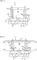
- FIG. 2a An example of an arrangement according to an example of the invention is shown in Fig. 2a .
- the arrangement comprises electrical heating rods 13a, a temperature sensor 15 and a first conduit 12a and a second conduit 12b in fluid connection with a first cavity 9a and a second cavity 9b.
- the second cavity 9b is preferably an annular cavity as illustrated in the cross section of evacuation cup 8 shown in Fig. 2b ; the cross-section is generated from the A-A cutting plane indicated in Fig. 2a .
- four electrical heating rods 13a are arranged symmetrically about an axis extending outward from the evacuation hole 4.
- the evacuation cup 8 comprises heat transfer capabilities sufficient for distributing the heat generated from the electrical heating rods 13a in the housing wall 8' such that temperature of the housing wall 8' becomes more uniform around the perimeter of the first cavity 9a.
- Fig. 2c shows a cross section of evacuation cup 8 shown in Fig. 2b , the cross-section is generated from the B-B cutting plane indicated in Fig. 2a .
- the cross-section illustrates the circular shape of the evacuation cup 8.
- the housing wall 8' is shown extending across the first cavity 9a and second cavity 9b and enclosing these.
- the evacuation cup 8 may comprise the first heating arrangement 13 and also a second heating arrangement 19.
- the arrangement comprises a first heating arrangement 13 and a second heating arrangement 19 and the VIG unit 1 is arranged with a glass tube 14 placed in the evacuation hole 4, through which tube 14 the void 3 can be evacuated.
- the frit soldering material 7 is arranged around the tube 14 and is heat-treated using the first heating arrangement 13 in order to create a hermetic seal between the tube 14 and the first glass pane 2a.
- the seal is preferably obtained prior to evacuation of the void 3 such that gas is evacuated through the tube 14 only.
- the tube 14 is sealed by heating the tip of the tube 14, thereby fully enclosing the void 3.
- the tube 14 is in the present examples sealed by heat provided by the second heating arrangement 19.
- the soldering frit material 7 is heated using electrical heating rods 13a embedded in the housing wall 8' and the tip of the tube 14 is heated using a second heating arrangement 19 comprising a radiation source 19a providing thermal radiation to the tube 14.
- the tube 14 is irradiated by suitable electromagnetic radiation, such as laser, microwave or IR radiation for a sufficient amount of time for melting the tip of the tube 14 and seal it such that no gas can transfer between the void 3 and the outside of the VIG unit 1.
- the radiation source is located outside the evacuation cup 8, and may not be in connection with the evacuation cup 8.
- a window 21 is provided in the housing wall 8' of the evacuation cup 8, which allows the radiation to be transmitted to the tip of the tube 14.
- Fig. 3b shows an arrangement having a second heating arrangement 19 comprising a heating element 19b positioned inside the first cavity 9a.
- the second heating arrangement 19 is placed in connection with housing wall 8' at a position above the tip of the tube 14.
- the second heating arrangement 19 may comprise a heat element 19b suitable for heating the tip of the tube 14 to approximately 900-1200 degrees Celsius, such as a tungsten coil or a ceramic heating element.
- the second heating arrangement 19 is configured to provide sufficient heating for the tip of the tube 14 at pressures from atmospheric to vacuum pressure.
- the first heating arrangement 13 is configured to heat the housing wall 8' to a second temperature (T2) which is higher than a first temperature (T1) of the air surrounding the outside the evacuation cup 8.
- the housing wall 8' is configured such that an increase in temperature of the housing wall 8' provides an increase in temperature of the elements enclosed by the housing wall 8', such as the air inside the first cavity 9a, the soldering frit material 7 and the part of the first glass pane 2a covered by the evacuation cup 8.
- One purpose of the heating of the elements enclosed by the housing wall 8' is to compensate for the shielding effect of the housing wall 8' which causes the temperature of the elements inside the housing wall 8' to be heated with a time delay as compared to the air in the furnace and outside the housing wall 8'.
- the soldering frit material 7 and the first pane 2a inside the first cavity 9a are in one preferred embodiment heated to substantially the same temperature as the remaining part of the first glass pane 2a by heating the air inside the first cavity 9a to substantially the same temperature as the air surrounding the outside of the housing wall 8' of the evacuation cup 8 such that the soldering frit material 7 forms a hermetic seal, which is in a substantially non-flowing state when the evacuation of the void 3 to a vacuum state is to be initiated.
- the VIG unit 1 may be produced inside a furnace 20.
- the air surrounding the outside of the evacuation cup 8 may be heated to the first temperature (T1) by a furnace 20 and the first temperature (T1) may be utilized to soften soldering frit material between and around the periphery of the glass panes such that a side seal 6 is formed.
- the first temperature (T1) provided by the furnace 20 is preferably high enough, e.g. least 275 degrees Celsius, in order to efficiently vaporize any contaminants and to provide an optimal thermal cleaning process of the VIG unit 1 during the evacuation of the void 3.
- each VIG unit 1 is arranged with an arrangement according to one or more examples of the invention.
- the arrangements are in fluid connection with one or more evacuation pumps 18.
- the arrangements, and especially the first heating arrangement 13 and possible second heating arrangement 19 and additionally the temperature sensor 15 within the housing wall 8' are in communication with one or more control arrangements 16.
- the control arrangement 16 may be configured to adjust the temperature of the housing wall 8', such that the temperature of the air within first cavity 9a is the same or different from the air surrounding the evacuation cup 8.
- the temperature sensor 15 is configured to register the temperature in the evacuation cup 8 and to send an output accordingly to the control arrangement 16.
- the control arrangement 16 is configured to control the first heating arrangement 13 based on the output received from the temperature sensor 15.
- This feedback system such as a PID controller system, may be comprised in the control arrangement 16 for automatically controlling the temperatures of the housing wall 8' and indirectly also the first cavity 9a and the soldering frit material 7 according to predetermined temperature profiles for the VIG unit production, such as a predetermined temperature profile for producing a hermetic seal from the soldering frit material 7 provided around the evacuation hole 4.
- the control arrangement 16 may also configured to control the furnace 20 and the pumps 18.
- the evacuation cup 8 is placed on the first glass pane 2a such that the first plane land 11a is in connection with the first glass pane 2a, such that they are in abutment, preferably with a sealing material or gasket provided. If the evacuation cup 8 has a second plane lane 11b, this is also in abutment with the first glass pane 2a, or in connection with the first glass pane 2a via a seal or gasket.
- the second temperature (T2) is measured using a temperature sensor 15 which sends an output accordingly to the control arrangement 16 which in turn controls the first heating arrangement 13 based on the output received from the temperature sensor 15.
- the control of the first heating arrangement 16 may be done automatically based on the output.
- the control arrangement 16 may be configured to control the first heating arrangement 13 such that it follows a predetermined temperature profile.
- the first heating arrangement 13 may be set to heat the soldering frit material 7 to 350 degrees Celsius for 30 minutes and then thereafter heat to 390 degrees Celsius for 40 minutes.
- the soldering frit material 7 may be heated to a temperature which is 20-50 degrees Celsius higher than the temperature at which the soldering frit material 7 will flow. This higher temperature may be a temperature about 420 degrees Celsius.
- the soldering frit material 7 around the evacuation hole 4 is heat-treated separately from the side seal 6.
- the heat generated can be focused on the soldering frit material 7, such that e.g. the first glass pane 2a covered by the first cavity 9a of the evacuation cup 8 is only minimally affected by heated housing wall 8'.
- the soldering frit material 7 After heating the soldering frit material 7 to a flowing state and cooling it subsequently, the soldering frit material 7 is in a non-flowing state at which time it is safe to initiate the evacuation of the void 3 without compromising the efficiency of the seal provided by the soldering frit material 7. If the evacuation is initiated too soon, the soldering frit material 7 may become detached from the surfaces.
- the void 3 is evacuated by a pump 18, via the first conduit 12a and the first cavity 9a.
- the pressure to be reached inside the void 3 is preferably at least 10 -3 mbar.
- a tube 14 is provided in the evacuation hole 4, with the soldering frit material 7 placed between the outside of the tube 14 and the first glass pane 2a such that the void 3 may be evacuated via the tube 14.
- the evacuation hole 4 is closed by either heating the soldering frit material 7 such that it extends across the evacuation hole 4 or by sealing the tube 14.
- the second heating arrangement 19 may be moved towards the tube tip to provide a local heating of the tip of the tube 14.
Landscapes
- Engineering & Computer Science (AREA)
- Civil Engineering (AREA)
- Structural Engineering (AREA)
- Physics & Mathematics (AREA)
- Thermal Sciences (AREA)
- Joining Of Glass To Other Materials (AREA)
Claims (12)
- Coupelle d'évacuation (8) pour fournir un vide à une unité de vitrage isolant sous vide comprenant un vide (3) enfermé entre deux vitres (2a, 2b), dans laquelle un trou d'évacuation (4) est prévu à travers l'une des vitres (2a, 2b), la coupelle d'évacuation (8) comprenant- une paroi de boîtier (8'),- une première cavité (9a) à l'intérieur de la paroi de boîtier (8') agencée pour être en communication fluidique avec le trou d'évacuation (4) de l'unité de vitrage isolant sous vide (1) au moyen d'une première ouverture (10a) de la première cavité (9a),- une première plage plane (11a) enfermant la première ouverture (10a),- un premier conduit (12a) à travers la paroi de boîtier (8') et en communication fluidique avec la première cavité (9a), et- un premier dispositif de chauffage (13) placé à l'extérieur de la première cavité (9a) de la coupelle d'évacuation (8), le premier dispositif de chauffage (13) étant agencé pour chauffer la paroi de boîtier (8') de manière répartie le long du périmètre de la première cavité (9a), le premier dispositif de chauffage (13) comprenant au moins deux tiges de chauffage électrique (13a) s'étendant essentiellement perpendiculairement au plan de la première ouverture (10a), de préférence au moins trois de telles tiges de chauffage (13a), et les tiges de chauffage électrique (13a) étant agencées pour chauffer la paroi de boîtier (8') à des positions réparties essentiellement uniformément le long du périmètre de la première cavité (9a),caractérisée en ce que les tiges de chauffage électrique (13a) du premier dispositif de chauffage (13) sont situées essentiellement à l'intérieur de la paroi de boîtier (8') avec une partie de celle-ci faisant saillie à l'extérieur de la paroi de boîtier (8').
- Coupelle d'évacuation (8) selon la revendication 1, comprenant en outre un dispositif de commande (16) pour commander le fonctionnement du premier dispositif de chauffage (13) de manière à chauffer la paroi de boîtier (8') de la coupelle d'évacuation (8) à une deuxième température (T2) au moyen du premier dispositif de chauffage (13), la deuxième température étant supérieure d'au moins 5°C, de préférence supérieure d'au moins 8°C, telle qu'au moins 12°C supérieure à la température de l'air entourant l'extérieur de la coupelle d'évacuation (8).
- Coupelle d'évacuation (8) selon l'une quelconque des revendications 1 et 2, comprenant en outre une deuxième plage plane (11b) enfermant la première plage plane (11a) et définissant une deuxième cavité (9b) à l'intérieur de la paroi de boîtier (8') avec un deuxième ouverture (10b) située entre la première plage plane (11a) et la deuxième plage plane (11b), un deuxième conduit (12b) reliant la deuxième cavité (9b) et l'extérieur de la paroi de boîtier (8'), dans laquelle la première plage plane (11a) et la deuxième plage plane (11b) ont de préférence une forme annulaire concentrique.
- Coupelle d'évacuation (8) selon l'une quelconque des revendications 1 à 3, dans laquelle le dispositif comprend en outre un deuxième élément chauffant (19b) placé à l'intérieur de la première cavité (9a) pour chauffer une pointe distale d'un tube (14) s'étendant depuis le trou (4) de manière à l'obturer.
- Coupelle d'évacuation (8) selon les revendications 2 et 4, dans laquelle le dispositif de commande (16) est en outre agencé pour commander le fonctionnement du deuxième dispositif de chauffage (19).
- Coupelle d'évacuation (8) selon l'une quelconque des revendications 2 à 5, comprenant un capteur de température (15) disposé dans chaque coupelle d'évacuation (8) pour mesurer une température et fournir une sortie en fonction du dispositif de commande (16).
- Coupelle d'évacuation (8) selon l'une quelconque des revendications 1 à 6, dans laquelle le diamètre de la coupelle d'évacuation (8) mesurée parallèlement à la première surface plane (11a) n'est pas supérieur à 50 mm, tel que 45 mm.
- Procédé pour fournir un vide à une unité de vitrage isolant sous vide (1) comprenant un vide (3) enfermé entre deux vitres (2a, 2b), dans lequel un trou d'évacuation (4) est prévu à travers une première vitre des vitres (2a), le procédé comprenant les étapes consistant à- disposer une coupelle d'évacuation (8) selon l'une quelconque des revendications 1 à 7 sur la première vitre (2a) de sorte que le trou d'évacuation (4) soit en communication fluidique avec une première cavité (9a) ménagée dans une paroi de boîtier (8') de la coupelle d'évacuation (8) au moyen d'une première ouverture (10a) de la première cavité (9a),- placer l'unité de vitrage isolant sous vide (1) dans un four (20),- chauffer l'air de l'intérieur du four (20) avec l'unité de vitrage isolant sous vide (1) à une première température (T1),- chauffer la paroi de boîtier (8') de la coupelle d'évacuation (8) à une deuxième température (T2) au moyen du premier dispositif de chauffage (13) tandis que la température d'air du four (20) est à ladite première température (T1), la deuxième température (T2) étant supérieure ou égale à 5°C, de préférence d'au moins 8°C, telle qu'au moins 12°C supérieure à la première température (T1), et- évacuer le vide (3) en pompant la première cavité (9a) de la coupelle d'évacuation (8) à travers un premier conduit (12a) traversant la paroi de boîtier (8') et en communication fluidique avec la première cavité (9a).
- Procédé selon la revendication 8, comprenant en outre l'étape de maintien de la température de l'air du four (20) à ladite première température (T1) tandis que la paroi de boîtier (8') est maintenue à ladite deuxième température (T2) pendant au moins 5 minutes, de préférence au moins pendant 10 minutes, de manière à chauffer un matériau de soudure (7) entourant le trou d'évacuation (4).
- Procédé selon la revendication 9, dans lequel le matériau de soudure (7) est chauffé jusqu'à un état où il s'écoule et / ou dans lequel le matériau de soudure (7) est chauffé après que l'évacuation du vide (3) est réalisée de manière à sceller le trou d'évacuation (4).
- Procédé selon l'une quelconque des revendications 8 à 10, dans lequel la paroi de boîtier (8') de la coupelle d'évacuation (8) est chauffée si bien que la température de la première vitre (2a) recouverte par la première cavité (9a) de la coupelle (8) est essentiellement la même que la température de la première vitre (2a) qui n'est pas recouverte par la coupelle d'évacuation (8).
- Procédé selon l'une quelconque des revendications 8 à 11, dans lequel le procédé comprend l'étape consistant à chauffer une pointe distale d'un tube (14) s'étendant depuis le trou d'évacuation (4) au moyen d'un deuxième dispositif de chauffage (19) de manière à le sceller, dans lequel la coupelle d'évacuation (8) comprend en outre de préférence un deuxième élément chauffant (19b) placé à l'intérieur de la première cavité (9a).
Priority Applications (2)
| Application Number | Priority Date | Filing Date | Title |
|---|---|---|---|
| PL18156478T PL3363983T3 (pl) | 2017-02-17 | 2018-02-13 | Izolowana próżniowo szyba zespolona |
| US15/899,830 US10633913B2 (en) | 2017-02-17 | 2018-02-20 | Vacuum insulated glazing unit |
Applications Claiming Priority (1)
| Application Number | Priority Date | Filing Date | Title |
|---|---|---|---|
| DKPA201770111 | 2017-02-17 |
Publications (2)
| Publication Number | Publication Date |
|---|---|
| EP3363983A1 EP3363983A1 (fr) | 2018-08-22 |
| EP3363983B1 true EP3363983B1 (fr) | 2021-10-27 |
Family
ID=61198765
Family Applications (1)
| Application Number | Title | Priority Date | Filing Date |
|---|---|---|---|
| EP18156478.2A Active EP3363983B1 (fr) | 2017-02-17 | 2018-02-13 | Unité de vitrage isolée sous vide |
Country Status (3)
| Country | Link |
|---|---|
| US (1) | US10633913B2 (fr) |
| EP (1) | EP3363983B1 (fr) |
| PL (1) | PL3363983T3 (fr) |
Families Citing this family (2)
| Publication number | Priority date | Publication date | Assignee | Title |
|---|---|---|---|---|
| WO2019224358A1 (fr) * | 2018-05-24 | 2019-11-28 | Vkr Holding A/S | Feuilletage d'unités vig |
| CN110439436B (zh) * | 2019-08-27 | 2020-05-12 | 海门市贝斯特钢化玻璃有限公司 | 一种中空玻璃惰性气体充气机 |
Citations (1)
| Publication number | Priority date | Publication date | Assignee | Title |
|---|---|---|---|---|
| JP2002128544A (ja) * | 2000-10-19 | 2002-05-09 | Nippon Sheet Glass Co Ltd | 真空複層パネルの製造方法 |
Family Cites Families (14)
| Publication number | Priority date | Publication date | Assignee | Title |
|---|---|---|---|---|
| DE69429699T2 (de) | 1993-09-27 | 2002-08-14 | Saint Gobain | Isolierverglasung und Vakuumerzeugungsverfahren dafür |
| JPH11240739A (ja) | 1998-02-26 | 1999-09-07 | Asahi Glass Co Ltd | 複層ガラスの製造方法およびその装置 |
| AUPP712198A0 (en) | 1998-11-13 | 1998-12-10 | University Of Sydney, The | Method of and apparatus for evacuating a glass chamber |
| JP2000195426A (ja) * | 1998-12-28 | 2000-07-14 | Canon Inc | 封止方法及び密封容器と画像表示装置及び真空排気装置 |
| CN1209545C (zh) | 2002-08-14 | 2005-07-06 | 青岛亨达海特机械有限公司 | 一种制造真空玻璃的新工艺 |
| JP2004265775A (ja) | 2003-03-03 | 2004-09-24 | Nippon Sheet Glass Co Ltd | 減圧処理装置 |
| US8500933B2 (en) * | 2007-12-14 | 2013-08-06 | Guardian Industries Corp. | Localized heating of edge seals for a vacuum insulating glass unit, and/or unitized oven for accomplishing the same |
| US8137494B2 (en) * | 2007-12-14 | 2012-03-20 | Guardian Industries Corp. | Vacuum insulating glass unit with large pump-out port, and/or method of making the same |
| US8866237B2 (en) * | 2012-02-27 | 2014-10-21 | Texas Instruments Incorporated | Methods for embedding controlled-cavity MEMS package in integration board |
| CN108178526A (zh) * | 2012-05-18 | 2018-06-19 | 松下知识产权经营株式会社 | 多层玻璃的制备方法 |
| CN103570229B (zh) | 2012-08-10 | 2015-11-25 | 北京新立基真空玻璃技术有限公司 | 真空抽取装置、真空玻璃制作系统以及相关方法 |
| US10465436B2 (en) * | 2015-08-20 | 2019-11-05 | Vkr Holding A/S | Evacuation head with ceramic heater for VIG unit manufacture |
| PL3337942T3 (pl) * | 2015-08-20 | 2020-06-29 | Vkr Holding A/S | Sposób wytwarzania próżniowo izolowanego zespołu okiennego o ulepszonym profilu temperaturowym |
| EP3337943B1 (fr) * | 2015-08-20 | 2020-10-14 | VKR Holding A/S | Tête d'évacuation de petit diamètre pour fabrication d'unité de vig |
-
2018
- 2018-02-13 EP EP18156478.2A patent/EP3363983B1/fr active Active
- 2018-02-13 PL PL18156478T patent/PL3363983T3/pl unknown
- 2018-02-20 US US15/899,830 patent/US10633913B2/en active Active
Patent Citations (1)
| Publication number | Priority date | Publication date | Assignee | Title |
|---|---|---|---|---|
| JP2002128544A (ja) * | 2000-10-19 | 2002-05-09 | Nippon Sheet Glass Co Ltd | 真空複層パネルの製造方法 |
Also Published As
| Publication number | Publication date |
|---|---|
| PL3363983T3 (pl) | 2022-02-21 |
| US20180238104A1 (en) | 2018-08-23 |
| EP3363983A1 (fr) | 2018-08-22 |
| US10633913B2 (en) | 2020-04-28 |
Similar Documents
| Publication | Publication Date | Title |
|---|---|---|
| EP1216971A1 (fr) | Procede de fabrication de vitrage sous vide et systeme mecanique d'application | |
| RU2470129C2 (ru) | Локальное нагревание краевых уплотнений для вакуумного изоляционного стеклопакета и/или унифицированная печь для осуществления данного стеклопакета | |
| EP3392214B1 (fr) | Procédé de fabrication de verre sous vide trempé et ligne de production associée | |
| US8460493B2 (en) | Evacuation and port sealing techniques for vacuum insulating glass units, and/or vacuum oven for accomplishing the same | |
| EP3363983B1 (fr) | Unité de vitrage isolée sous vide | |
| EP3438402B1 (fr) | Procédé de fabrication d'ensemble panneau de verre, procédé de fabrication de raccord de fixation, dispositif de fabrication d'ensemble panneau de verre, et ensemble panneau de verre | |
| US11130706B2 (en) | Methods for manufacturing tempered vacuum glass and production lines therefor | |
| KR20150016570A (ko) | 감소된 봉지 높이의 편차를 갖는 진공 단열 유리(vig) 윈도우 유닛 및 그 제조방법 | |
| US10465436B2 (en) | Evacuation head with ceramic heater for VIG unit manufacture | |
| CN104466034A (zh) | 一种激光烧结设备及烧结方法 | |
| CN108138534B (zh) | 具有改善的温度曲线的用于生产vig装置的方法 | |
| EP3363982B1 (fr) | Unité de vitrage isolé sous vide | |
| CN105502968A (zh) | 一种真空玻璃的金属封接方法 | |
| EP3337943B1 (fr) | Tête d'évacuation de petit diamètre pour fabrication d'unité de vig | |
| US20200040645A1 (en) | Vacuum Insulated Glazing Unit | |
| JP2022537955A (ja) | 真空絶縁ガラス(vig)ユニットの真空引き及び密封封止のためのフランジ付きチューブ、フランジ付きチューブを含むvigユニット、及び関連する方法 | |
| KR20190024313A (ko) | 진공 유리 패널 및 그 제조 방법 | |
| US20210388667A1 (en) | Glass unit | |
| US20220074260A1 (en) | Vig unit with temporary evacuation gap in perimeter seal | |
| JP6873655B2 (ja) | Rf周波数ウィンドウ | |
| US20220235601A1 (en) | Manufacturing of vacuum insulated glazing unit | |
| KR20210110632A (ko) | 진공 단열 유리(vig) 유닛의 배기 및 기밀 밀봉을 위한 통합형 튜브, 통합형 튜브를 포함하는 vig 유닛, 및 연관된 방법 |
Legal Events
| Date | Code | Title | Description |
|---|---|---|---|
| PUAI | Public reference made under article 153(3) epc to a published international application that has entered the european phase |
Free format text: ORIGINAL CODE: 0009012 |
|
| STAA | Information on the status of an ep patent application or granted ep patent |
Free format text: STATUS: THE APPLICATION HAS BEEN PUBLISHED |
|
| AK | Designated contracting states |
Kind code of ref document: A1 Designated state(s): AL AT BE BG CH CY CZ DE DK EE ES FI FR GB GR HR HU IE IS IT LI LT LU LV MC MK MT NL NO PL PT RO RS SE SI SK SM TR |
|
| AX | Request for extension of the european patent |
Extension state: BA ME |
|
| STAA | Information on the status of an ep patent application or granted ep patent |
Free format text: STATUS: REQUEST FOR EXAMINATION WAS MADE |
|
| STAA | Information on the status of an ep patent application or granted ep patent |
Free format text: STATUS: EXAMINATION IS IN PROGRESS |
|
| 17P | Request for examination filed |
Effective date: 20180830 |
|
| RBV | Designated contracting states (corrected) |
Designated state(s): AL AT BE BG CH CY CZ DE DK EE ES FI FR GB GR HR HU IE IS IT LI LT LU LV MC MK MT NL NO PL PT RO RS SE SI SK SM TR |
|
| 17Q | First examination report despatched |
Effective date: 20180924 |
|
| STAA | Information on the status of an ep patent application or granted ep patent |
Free format text: STATUS: EXAMINATION IS IN PROGRESS |
|
| RIN1 | Information on inventor provided before grant (corrected) |
Inventor name: KRISKO, ANNETTE JOHNCOCK Inventor name: SOENDERKAER, PETER Inventor name: MIKKELSEN, THOMAS VILLIAM SEJER |
|
| GRAP | Despatch of communication of intention to grant a patent |
Free format text: ORIGINAL CODE: EPIDOSNIGR1 |
|
| STAA | Information on the status of an ep patent application or granted ep patent |
Free format text: STATUS: GRANT OF PATENT IS INTENDED |
|
| GRAS | Grant fee paid |
Free format text: ORIGINAL CODE: EPIDOSNIGR3 |
|
| INTG | Intention to grant announced |
Effective date: 20210826 |
|
| GRAA | (expected) grant |
Free format text: ORIGINAL CODE: 0009210 |
|
| STAA | Information on the status of an ep patent application or granted ep patent |
Free format text: STATUS: THE PATENT HAS BEEN GRANTED |
|
| AK | Designated contracting states |
Kind code of ref document: B1 Designated state(s): AL AT BE BG CH CY CZ DE DK EE ES FI FR GB GR HR HU IE IS IT LI LT LU LV MC MK MT NL NO PL PT RO RS SE SI SK SM TR |
|
| REG | Reference to a national code |
Ref country code: GB Ref legal event code: FG4D |
|
| REG | Reference to a national code |
Ref country code: CH Ref legal event code: EP |
|
| REG | Reference to a national code |
Ref country code: AT Ref legal event code: REF Ref document number: 1441940 Country of ref document: AT Kind code of ref document: T Effective date: 20211115 |
|
| REG | Reference to a national code |
Ref country code: DE Ref legal event code: R096 Ref document number: 602018025521 Country of ref document: DE |
|
| REG | Reference to a national code |
Ref country code: IE Ref legal event code: FG4D |
|
| REG | Reference to a national code |
Ref country code: LT Ref legal event code: MG9D |
|
| REG | Reference to a national code |
Ref country code: NL Ref legal event code: MP Effective date: 20211027 |
|
| REG | Reference to a national code |
Ref country code: AT Ref legal event code: MK05 Ref document number: 1441940 Country of ref document: AT Kind code of ref document: T Effective date: 20211027 |
|
| PG25 | Lapsed in a contracting state [announced via postgrant information from national office to epo] |
Ref country code: RS Free format text: LAPSE BECAUSE OF FAILURE TO SUBMIT A TRANSLATION OF THE DESCRIPTION OR TO PAY THE FEE WITHIN THE PRESCRIBED TIME-LIMIT Effective date: 20211027 Ref country code: LT Free format text: LAPSE BECAUSE OF FAILURE TO SUBMIT A TRANSLATION OF THE DESCRIPTION OR TO PAY THE FEE WITHIN THE PRESCRIBED TIME-LIMIT Effective date: 20211027 Ref country code: FI Free format text: LAPSE BECAUSE OF FAILURE TO SUBMIT A TRANSLATION OF THE DESCRIPTION OR TO PAY THE FEE WITHIN THE PRESCRIBED TIME-LIMIT Effective date: 20211027 Ref country code: BG Free format text: LAPSE BECAUSE OF FAILURE TO SUBMIT A TRANSLATION OF THE DESCRIPTION OR TO PAY THE FEE WITHIN THE PRESCRIBED TIME-LIMIT Effective date: 20220127 Ref country code: AT Free format text: LAPSE BECAUSE OF FAILURE TO SUBMIT A TRANSLATION OF THE DESCRIPTION OR TO PAY THE FEE WITHIN THE PRESCRIBED TIME-LIMIT Effective date: 20211027 |
|
| PG25 | Lapsed in a contracting state [announced via postgrant information from national office to epo] |
Ref country code: IS Free format text: LAPSE BECAUSE OF FAILURE TO SUBMIT A TRANSLATION OF THE DESCRIPTION OR TO PAY THE FEE WITHIN THE PRESCRIBED TIME-LIMIT Effective date: 20220227 Ref country code: SE Free format text: LAPSE BECAUSE OF FAILURE TO SUBMIT A TRANSLATION OF THE DESCRIPTION OR TO PAY THE FEE WITHIN THE PRESCRIBED TIME-LIMIT Effective date: 20211027 Ref country code: PT Free format text: LAPSE BECAUSE OF FAILURE TO SUBMIT A TRANSLATION OF THE DESCRIPTION OR TO PAY THE FEE WITHIN THE PRESCRIBED TIME-LIMIT Effective date: 20220228 Ref country code: NO Free format text: LAPSE BECAUSE OF FAILURE TO SUBMIT A TRANSLATION OF THE DESCRIPTION OR TO PAY THE FEE WITHIN THE PRESCRIBED TIME-LIMIT Effective date: 20220127 Ref country code: NL Free format text: LAPSE BECAUSE OF FAILURE TO SUBMIT A TRANSLATION OF THE DESCRIPTION OR TO PAY THE FEE WITHIN THE PRESCRIBED TIME-LIMIT Effective date: 20211027 Ref country code: LV Free format text: LAPSE BECAUSE OF FAILURE TO SUBMIT A TRANSLATION OF THE DESCRIPTION OR TO PAY THE FEE WITHIN THE PRESCRIBED TIME-LIMIT Effective date: 20211027 Ref country code: HR Free format text: LAPSE BECAUSE OF FAILURE TO SUBMIT A TRANSLATION OF THE DESCRIPTION OR TO PAY THE FEE WITHIN THE PRESCRIBED TIME-LIMIT Effective date: 20211027 Ref country code: GR Free format text: LAPSE BECAUSE OF FAILURE TO SUBMIT A TRANSLATION OF THE DESCRIPTION OR TO PAY THE FEE WITHIN THE PRESCRIBED TIME-LIMIT Effective date: 20220128 Ref country code: ES Free format text: LAPSE BECAUSE OF FAILURE TO SUBMIT A TRANSLATION OF THE DESCRIPTION OR TO PAY THE FEE WITHIN THE PRESCRIBED TIME-LIMIT Effective date: 20211027 |
|
| REG | Reference to a national code |
Ref country code: DE Ref legal event code: R097 Ref document number: 602018025521 Country of ref document: DE |
|
| PG25 | Lapsed in a contracting state [announced via postgrant information from national office to epo] |
Ref country code: SM Free format text: LAPSE BECAUSE OF FAILURE TO SUBMIT A TRANSLATION OF THE DESCRIPTION OR TO PAY THE FEE WITHIN THE PRESCRIBED TIME-LIMIT Effective date: 20211027 Ref country code: SK Free format text: LAPSE BECAUSE OF FAILURE TO SUBMIT A TRANSLATION OF THE DESCRIPTION OR TO PAY THE FEE WITHIN THE PRESCRIBED TIME-LIMIT Effective date: 20211027 Ref country code: RO Free format text: LAPSE BECAUSE OF FAILURE TO SUBMIT A TRANSLATION OF THE DESCRIPTION OR TO PAY THE FEE WITHIN THE PRESCRIBED TIME-LIMIT Effective date: 20211027 Ref country code: EE Free format text: LAPSE BECAUSE OF FAILURE TO SUBMIT A TRANSLATION OF THE DESCRIPTION OR TO PAY THE FEE WITHIN THE PRESCRIBED TIME-LIMIT Effective date: 20211027 Ref country code: DK Free format text: LAPSE BECAUSE OF FAILURE TO SUBMIT A TRANSLATION OF THE DESCRIPTION OR TO PAY THE FEE WITHIN THE PRESCRIBED TIME-LIMIT Effective date: 20211027 Ref country code: CZ Free format text: LAPSE BECAUSE OF FAILURE TO SUBMIT A TRANSLATION OF THE DESCRIPTION OR TO PAY THE FEE WITHIN THE PRESCRIBED TIME-LIMIT Effective date: 20211027 |
|
| PLBE | No opposition filed within time limit |
Free format text: ORIGINAL CODE: 0009261 |
|
| STAA | Information on the status of an ep patent application or granted ep patent |
Free format text: STATUS: NO OPPOSITION FILED WITHIN TIME LIMIT |
|
| PG25 | Lapsed in a contracting state [announced via postgrant information from national office to epo] |
Ref country code: MC Free format text: LAPSE BECAUSE OF FAILURE TO SUBMIT A TRANSLATION OF THE DESCRIPTION OR TO PAY THE FEE WITHIN THE PRESCRIBED TIME-LIMIT Effective date: 20211027 |
|
| 26N | No opposition filed |
Effective date: 20220728 |
|
| REG | Reference to a national code |
Ref country code: CH Ref legal event code: PL |
|
| REG | Reference to a national code |
Ref country code: BE Ref legal event code: MM Effective date: 20220228 |
|
| PG25 | Lapsed in a contracting state [announced via postgrant information from national office to epo] |
Ref country code: LU Free format text: LAPSE BECAUSE OF NON-PAYMENT OF DUE FEES Effective date: 20220213 Ref country code: AL Free format text: LAPSE BECAUSE OF FAILURE TO SUBMIT A TRANSLATION OF THE DESCRIPTION OR TO PAY THE FEE WITHIN THE PRESCRIBED TIME-LIMIT Effective date: 20211027 |
|
| PG25 | Lapsed in a contracting state [announced via postgrant information from national office to epo] |
Ref country code: SI Free format text: LAPSE BECAUSE OF FAILURE TO SUBMIT A TRANSLATION OF THE DESCRIPTION OR TO PAY THE FEE WITHIN THE PRESCRIBED TIME-LIMIT Effective date: 20211027 |
|
| PG25 | Lapsed in a contracting state [announced via postgrant information from national office to epo] |
Ref country code: LI Free format text: LAPSE BECAUSE OF NON-PAYMENT OF DUE FEES Effective date: 20220228 Ref country code: IE Free format text: LAPSE BECAUSE OF NON-PAYMENT OF DUE FEES Effective date: 20220213 Ref country code: CH Free format text: LAPSE BECAUSE OF NON-PAYMENT OF DUE FEES Effective date: 20220228 |
|
| PG25 | Lapsed in a contracting state [announced via postgrant information from national office to epo] |
Ref country code: BE Free format text: LAPSE BECAUSE OF NON-PAYMENT OF DUE FEES Effective date: 20220228 |
|
| PGFP | Annual fee paid to national office [announced via postgrant information from national office to epo] |
Ref country code: FR Payment date: 20230123 Year of fee payment: 6 |
|
| PG25 | Lapsed in a contracting state [announced via postgrant information from national office to epo] |
Ref country code: IT Free format text: LAPSE BECAUSE OF FAILURE TO SUBMIT A TRANSLATION OF THE DESCRIPTION OR TO PAY THE FEE WITHIN THE PRESCRIBED TIME-LIMIT Effective date: 20211027 |
|
| PGFP | Annual fee paid to national office [announced via postgrant information from national office to epo] |
Ref country code: PL Payment date: 20230113 Year of fee payment: 6 |
|
| PG25 | Lapsed in a contracting state [announced via postgrant information from national office to epo] |
Ref country code: HU Free format text: LAPSE BECAUSE OF FAILURE TO SUBMIT A TRANSLATION OF THE DESCRIPTION OR TO PAY THE FEE WITHIN THE PRESCRIBED TIME-LIMIT; INVALID AB INITIO Effective date: 20180213 |
|
| PG25 | Lapsed in a contracting state [announced via postgrant information from national office to epo] |
Ref country code: MK Free format text: LAPSE BECAUSE OF FAILURE TO SUBMIT A TRANSLATION OF THE DESCRIPTION OR TO PAY THE FEE WITHIN THE PRESCRIBED TIME-LIMIT Effective date: 20211027 Ref country code: CY Free format text: LAPSE BECAUSE OF FAILURE TO SUBMIT A TRANSLATION OF THE DESCRIPTION OR TO PAY THE FEE WITHIN THE PRESCRIBED TIME-LIMIT Effective date: 20211027 |
|
| PGFP | Annual fee paid to national office [announced via postgrant information from national office to epo] |
Ref country code: DE Payment date: 20240116 Year of fee payment: 7 Ref country code: GB Payment date: 20240104 Year of fee payment: 7 |