EP3363976A1 - Opening by rotation limiting arrangement for a window or a door for limiting the rotation of a leaf of a window or a door - Google Patents
Opening by rotation limiting arrangement for a window or a door for limiting the rotation of a leaf of a window or a door Download PDFInfo
- Publication number
- EP3363976A1 EP3363976A1 EP18156674.6A EP18156674A EP3363976A1 EP 3363976 A1 EP3363976 A1 EP 3363976A1 EP 18156674 A EP18156674 A EP 18156674A EP 3363976 A1 EP3363976 A1 EP 3363976A1
- Authority
- EP
- European Patent Office
- Prior art keywords
- window
- wing
- door
- rotation limiting
- drehöffnungsbegrenzungsanordnung
- Prior art date
- Legal status (The legal status is an assumption and is not a legal conclusion. Google has not performed a legal analysis and makes no representation as to the accuracy of the status listed.)
- Granted
Links
- 230000000903 blocking effect Effects 0.000 claims abstract description 45
- 230000033001 locomotion Effects 0.000 claims abstract description 36
- 230000008878 coupling Effects 0.000 claims description 19
- 238000010168 coupling process Methods 0.000 claims description 19
- 238000005859 coupling reaction Methods 0.000 claims description 19
- 229910001220 stainless steel Inorganic materials 0.000 description 2
- 239000010935 stainless steel Substances 0.000 description 2
- XAGFODPZIPBFFR-UHFFFAOYSA-N aluminium Chemical compound [Al] XAGFODPZIPBFFR-UHFFFAOYSA-N 0.000 description 1
- 229910052782 aluminium Inorganic materials 0.000 description 1
- 230000005540 biological transmission Effects 0.000 description 1
- 238000006073 displacement reaction Methods 0.000 description 1
- 230000007257 malfunction Effects 0.000 description 1
- 238000009423 ventilation Methods 0.000 description 1
Images
Classifications
-
- E—FIXED CONSTRUCTIONS
- E05—LOCKS; KEYS; WINDOW OR DOOR FITTINGS; SAFES
- E05C—BOLTS OR FASTENING DEVICES FOR WINGS, SPECIALLY FOR DOORS OR WINDOWS
- E05C17/00—Devices for holding wings open; Devices for limiting opening of wings or for holding wings open by a movable member extending between frame and wing; Braking devices, stops or buffers, combined therewith
- E05C17/02—Devices for holding wings open; Devices for limiting opening of wings or for holding wings open by a movable member extending between frame and wing; Braking devices, stops or buffers, combined therewith by mechanical means
- E05C17/04—Devices for holding wings open; Devices for limiting opening of wings or for holding wings open by a movable member extending between frame and wing; Braking devices, stops or buffers, combined therewith by mechanical means with a movable bar or equivalent member extending between frame and wing
- E05C17/12—Devices for holding wings open; Devices for limiting opening of wings or for holding wings open by a movable member extending between frame and wing; Braking devices, stops or buffers, combined therewith by mechanical means with a movable bar or equivalent member extending between frame and wing consisting of a single rod
- E05C17/24—Devices for holding wings open; Devices for limiting opening of wings or for holding wings open by a movable member extending between frame and wing; Braking devices, stops or buffers, combined therewith by mechanical means with a movable bar or equivalent member extending between frame and wing consisting of a single rod pivoted at one end, and with the other end running along a guide member
- E05C17/28—Devices for holding wings open; Devices for limiting opening of wings or for holding wings open by a movable member extending between frame and wing; Braking devices, stops or buffers, combined therewith by mechanical means with a movable bar or equivalent member extending between frame and wing consisting of a single rod pivoted at one end, and with the other end running along a guide member with braking, clamping or securing means at the connection to the guide member
-
- E—FIXED CONSTRUCTIONS
- E05—LOCKS; KEYS; WINDOW OR DOOR FITTINGS; SAFES
- E05C—BOLTS OR FASTENING DEVICES FOR WINGS, SPECIALLY FOR DOORS OR WINDOWS
- E05C9/00—Arrangements of simultaneously actuated bolts or other securing devices at well-separated positions on the same wing
Definitions
- the invention relates to a Drehö Stammsbegrenzungsan extract for a window or a door for limiting the rotational opening movement of a wing of a window or a door.
- Object of the present invention is therefore to provide a Wheelö Stammsbegrenzean eleven, with a wing in a limited rotational opening position, for example, with an opening width of about 100 mm, can be reliably set so that the rotational opening position is maintained even at high wind loads.
- rotation limiting element Under a fixed frame-side rotation limiting element is understood here an element which is at least indirectly attached to the fixed frame.
- the rotation limiting element may be a bolt or a pin. It is also conceivable that the rotation limiting element is formed mushroom-head-shaped.
- the fixed frame-side rotation limiting element can be performed on Drehschulsbegrenzer when turning open the wing until it enters a stop position corresponding to a limited rotational opening position of the wing.
- the rotation limiting element can interact with the blocking element, so that the rotation limiting element is fixed on the rotary movement limiter.
- the wing is set in the limited rotational opening position.
- the blocking element prevents the rotation limiting element from moving in the opposite direction along the rotation limiting element guide.
- the blocking element may for example be made of stainless steel, so that it is designed to be particularly stable and reliable locking is ensured even at high wind loads.
- the Drehzisbesky may be formed, for example, of aluminum.
- the blocking element is driven by a drive rod.
- the drive rod which can be initiated by an actuating handle, the blocking element to be moved, in particular to be moved from a release position to a blocking position in which it locks the rotation limiting element.
- a locked rotational opening position can be adjusted.
- the blocking element can be moved from a release position into a blocking position and back when the blocking element is rotatable, in particular rotatable about a vertical axis of rotation, in or on the rotational movement limiter. If the blocking element is rotated into a blocking position, it can block the rotation limiting element with a portion, so that it can no longer be moved linearly relative to the rotational movement limiter.
- the locking element may comprise a pin which cooperates with a drive rod side guide.
- the pin can be arranged eccentrically on the blocking element. He can also protrude downwards in the direction of drive rod from the blocking element.
- the pin may be hardened to be formed particularly stable.
- the pin is arranged on a side facing away from the transmission of a drive rod fitting side of the locking element. This can prevent jamming and blockage.
- the drive rod side guide can be designed as a backdrop.
- the backdrop may have two substantially parallel sections, which are connected by a connecting portion.
- the blocking element has a in an unlocked position for Drehbegrenzungselement Entry open and a stop for the rotation limiting element performing recording.
- the rotation limiting element can be moved along the rotation limiting element guide until it reaches the receptacle of the blocking element.
- the inclusion of the locking element is a stop, so that the rotation opening movement is limited.
- the wing is now in a limited rotational opening position.
- the locking element can now be displaced, in particular rotated, in order to fix the rotation limiting element in its position.
- the wing is set in its limited rotational opening position.
- the blocking element has a rear grip for engaging behind the rotation limiting element.
- the rear grip may be formed as an undercut groove.
- an undercut groove can hold the rotation limiting element in position.
- the blocking element has a height stop for fixing the position of the blocking element in the rotary movement limiter.
- the height stop may be formed as an annular groove.
- the locking element can be inserted from below into the Drehtownsbegrenzer. The height stop prevents the locking element, the rotary motion limiter on the leaves the opposite side, and ensures that the blocking element is arranged at the correct height on the rotary movement limiter.
- the Drehbegrenzungselement entry is slit-like and preferably extends in Falz prevalentsraum.
- the Drehbegrenzungselement entry may be formed as an undercut groove and thus the Drehbegrenzungselement, especially if this is mushroom-shaped, partially overlap, so that the rotation limiting element is securely held in the Drehbegrenzungselement entry and this particular can not leave upwards. As a result, the reliability of the Drehö Stammsbegrenzungsan ever is increased.
- a Drehbe dictionary be provided on which the rotation limiting element is arranged and which is pivotally mounted on a fixed frame.
- the Drehbe dictionary may for example be part of a so-called second pair of scissors.
- the rotation limiting element may in particular be arranged at the free end of the Drehbe dictionaryrarms.
- a wing-side coupling element which can be mounted in particular on a drive rod, is provided which, for a rotational opening limiting function, couples the rotation limiting element on the wing side and releases the rotation limiting element for a complete rotational opening.
- the rotation limiting element can be held on the wing. In this case, the wing can only be opened to a limited extent.
- the coupling element may have a locking portion and a release portion. With the locking section, the rotation limiting element can be held on the wing. If, however, the coupling element is displaced, in particular displaced in the circumferential direction of the wing, then a release section can release the rotation limiting element, so that a decoupling takes place.
- the rotational movement limiter may have a receptacle for the coupling element.
- the coupling element may be connected to the drive rod and thus be movable relative to the rotary motion limiter. If the coupling element can enter into the rotational movement limiter, the coupling element does not prevent that the drive rod can be displaced for a blocking position and thus the blocking element can be rotated.
- the scope of the invention also includes a window or a door having a rotary opening limiting arrangement according to the invention.
- a window or door having a rotary opening limiting arrangement according to the invention.
- Such a window or door withstands particularly high wind loads.
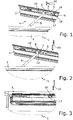
- the Fig. 1 shows a window 1 with a fixed frame 2 and a wing 3 in a view from above, wherein the wing 3 is a bit wide open.
- the open position of the wing 3 is limited by a Drehö Stammsbegrenzungsan eleven 4.
- the rotary opening limiting arrangement 4 comprises a rotary movement limiter 5, which is mounted on the wing 3 above a drive rod 6.
- the Drehterrorismsbeskyr 5 comprises a Drehbegrenzungselement Entry 7, which is designed like a slot and in which a rotation limiting element 8, the free end of a Drehbebankrarms 9 is arranged, is guided.
- the rotation limiting element 8 When opening the wing 3, the rotation limiting element 8 is moved in the guide 7 from right to left, wherein the Drehbegrenzeram 9 pivots relative to the fixed frame 2 in the position shown.
- the Drehbeskyram 9 is therefore arranged pivotably or rotatably on the fixed frame 2.
- the rotation limiting element 8 strikes against a stop, which will be shown later in detail, so that the wing 3 can not be opened further.
- An actuating handle 10, which is shown here only symbolically, is in a position which allows a rotational opening of the wing to a limited rotational opening position.
- the Fig. 2 essentially corresponds to the Fig. 1 ,
- the wing 3 is shown in a limited rotational opening position.
- the actuating handle 10 has been brought into a closed position. This means that the drive rod 6 has been moved. This had the consequence that a blocking element 12 was rotated in Drehschulsbegrenzer 5 so that it now locks the rotation limiting element 8, so that it can not be moved to the right.
- the rotation limiting element 8 is fixed with respect to the rotational movement limiter 5 in the position shown.
- the wing 3 can not be closed accordingly. In particular, the wing 3 can not be closed due to a gust of wind.
- the actuating handle 10 In order to close the wing 3 again, the actuating handle 10 must be made of in the Fig. 2 shown position again in the in the Fig. 1 rotated position shown so that the locking element 12 releases the rotation limiting element 8, so that the rotation limiting element 8 can be moved to the right along the Drehbegrenzungselement Insert 7 to close the wing
- the drive rod movement leads to a displacement of a drive rod-side guide 15, whereby the blocking element 12 is rotated. This will be explained in detail below.
- the Fig. 3 shows the window 1, wherein the wing 3 is closed.
- the actuating handle 10 has been brought into a third switching position, whereby a coupling element 16 which is attached to the drive rod 6, has been displaced to the right, so that a release portion 17 has come into coincidence with the rotation limiting element 8.
- the Drehbeskyram 9 is not pivoted and the wing 3 can be fully opened in rotation.
- the coupling element 16 moves to the right.
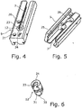
- the Fig. 4 shows a perspective top view of the Drehterrorismsbe dictionary 5.
- the Drehterrorismsbe dictionary 5 can be set, for example via grub screws 20, 21 on the wing 3.
- the blocking element 12 is arranged, which is rotatable relative to the Drehterrorismsbe dictionary 5.
- the rotation limiting element guide 7 opens into a receptacle 23 which is open towards the rotation limiting element guide 7.
- the blocking element 12 has an unlocking position or release position. If the blocking element 12 is rotated by a drive rod, the receptacle 23 no longer opens into the rotation limiting element guide 7, so that the rotation limiting element 8 can not be displaced into the rotation limiting element guide 7.
- the Figure 5 shows the Drehschisbe dictionary 5 in a perspective view from below.
- the rotation limiting element guide 7 as undercut groove is formed.
- the rotational movement limiter 5 has a receptacle 25 for the coupling element 16, so that it can be displaced into the region of the rotational movement limiter 5.
- a receptacle 26 for the blocking element 12 can be seen, wherein the blocking element 12 preferably from below, ie from the in the Fig. 5 shown side, is inserted in the mounting 26 in the mounting.
- the Fig. 6 shows the blocking element 12 in a perspective view.
- the blocking element 12 is substantially cylindrical. It shows the receptacle 23 with stop 24.
- the receptacle 23 is also formed as an undercut groove.
- the locking element 12 has a pin 30 which cooperates with a drive rod side guide, in particular the link 15.
- the pin 30 is arranged eccentrically on the blocking element 12.
- the blocking element 12 has an annular groove 31, by which the blocking element 12 is held in the rotary movement limiter 5 in the correct position, in particular height.
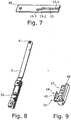
- the Fig. 7 shows an attachment 40, which is fastened to the drive rod 6.
- the attachment 40 has a trained as a gate 15 guide for the pin 30. If the drive rod 6 and thus the gate 15 is displaced relative to the pin 30, the pin passes from the straight gate section 15.1 via the gate section 15.2 in the straight gate section 15.3, which is arranged substantially parallel to the gate section 15.1. Due to the fact that the pin 30 comes from the gate section 15.1 to the gate section 15.3, the blocking element 12 is rotated and passes from a release position into a blocking position in which it defines the rotation limiting element 8 in its position on the rotary movement limiter 5. In an opposite espagnolette movement, the locking element 12 is rotated back, so that a release position is taken. The movement of the blocking element 12 takes place thus completely driven by a drive rod. In particular, no spring-loaded provision of the blocking element 12 is provided, since this could lead to malfunction.
- the Fig. 8 shows the Drehbe dictionary 9 in a view from below.
- the Drehbeskyram 9 is fixed via a frame attachment member 50 on the fixed frame 2 and is pivotable relative to the frame attachment member 50 and thus to the fixed frame 2.
- the rotation limiting element 8 is designed as a mushroom-shaped pin. The widening of the rotation limiting element 8 is, in particular, wider or has a larger diameter than the clear width of the rotation limiting element guide 7 and also the clear width of the receptacle 23, so that the rotation limiting element 8 is not mounted upward when the rotational movement limiter 5 is mounted on top of the window 1, or down, when the Drehierisbegrenzer 5 is mounted at the bottom of the window, can escape.
- the Fig. 9 shows the coupling element 16 with its release portion 17 and its locking portion 18.
- the coupling element 16 has over its length two opposite walls 41, 42, wherein the walls 41, 42 constitute a guide for the rotation limiting element 8.
- the wall 41 locks the rotation limiting element 8 when the wing 3 is not to be completely opened in rotation.
- a wall 42 opposite the wall is missing, so that the rotation limiting element 8 can be decoupled and thus the wing can be completely opened in rotation.
- the wall 41 is shorter than the wall 42.
Abstract
Bei einer Drehöffnungsbegrenzungsanordnung (4) für ein Fenster (1) oder eine Tür zur Begrenzung der Drehöffnungsbewegung eines Flügels (3) eines Fensters (1) oder einer Tür weist ein an einem Flügel (3) der Tür oder des Fensters (1) montierbarer Drehbewegungsbegrenzer (5) eine Drehbegrenzungselementführung (7) für ein festrahmenseitiges Drehbegrenzungselement (8) und ein Sperrelement (12) zur Festlegung des Drehbegrenzungselements (8) in einer begrenzten Drehöffnungsstellung auf.A rotary opening limiting arrangement (4) for a window (1) or a door for limiting the rotational opening movement of a wing (3) of a window (1) or a door has a rotary movement limiter mountable on a wing (3) of the door or window (1) (5) a rotation limiting element guide (7) for a fixed frame side rotation limiting element (8) and a blocking element (12) for fixing the rotation limiting element (8) in a limited rotary opening position.
Description
Die Erfindung betrifft eine Drehöffnungsbegrenzungsanordnung für ein Fenster oder eine Tür zur Begrenzung der Drehöffnungsbewegung eines Flügels eines Fensters oder einer Tür.The invention relates to a Drehöffnungsbegrenzungsanordnung for a window or a door for limiting the rotational opening movement of a wing of a window or a door.
Vielfach besteht die Anforderung, einen Flügel eines Fensters oder einer Tür nur ein Stück weit zu öffnen, um eine Lüftung realisieren zu können. Dabei soll verhindert werden, dass der Flügel vollständig drehöffnet. Andererseits sollte sichergestellt werden, dass der Flügel nicht zuschlägt. Der Flügel soll also in einer begrenzten Drehöffnungsstellung festgelegt werden können. Insbesondere, wenn Fenster in Hochhäusern eingebaut werden, sind bekannte Drehöffnungsbegrenzer nicht stabil genug, um auch bei hohen Windlasten das Zuschlagen eines Flügels, der sich in einer begrenzten Drehöffnungsstellung befindet, zu verhindern.Often there is the requirement to open a wing of a window or a door only a little way to realize a ventilation can. It should be prevented that the wing completely opened. On the other hand, it should be ensured that the wing does not strike. The wing should therefore be able to be set in a limited rotational opening position. In particular, when windows are installed in high-rise buildings, known Drehöffnungsbegrenzer are not stable enough to prevent the slamming of a wing, which is located in a limited rotational opening position, even at high wind loads.
Aufgabe der vorliegenden Erfindung ist es daher, eine Drehöffnungsbegrenzungsanordnung bereitzustellen, mit der ein Flügel in einer begrenzten Drehöffnungsstellung, beispielsweise bei einer Öffnungsweite von etwa 100 mm, zuverlässig festgelegt werden kann, sodass die Drehöffnungsstellung auch bei hohen Windlasten beibehalten wird.Object of the present invention is therefore to provide a Drehöffnungsbegrenzeanordnung, with a wing in a limited rotational opening position, for example, with an opening width of about 100 mm, can be reliably set so that the rotational opening position is maintained even at high wind loads.
Gelöst wird diese Aufgabe erfindungsgemäß durch eine Drehöffnungsbegrenzungsanordnung für ein Fenster oder eine Tür zur Begrenzung der Drehöffnungsbewegung eines Flügels eines Fensters oder einer Tür mit einem an einem Flügel der Tür oder des Fensters montierbaren Drehbewegungsbegrenzer, der eine Drehbegrenzungselementführung für ein festrahmenseitiges Drehbegrenzungselement und ein Sperrelement zur Festlegung des Drehbegrenzungselements in einer begrenzten Drehöffnungsstellung aufweist.This object is achieved according to the invention by a Drehöffnungsbegrenzungsanordnung for a window or a door for limiting the rotational opening movement of a wing of a window or door with a mountable on a wing of the door or window Drehbewegungsbegrenzer, a Drehbegrenzungselementführung for a fixed frame side rotation limiting element and a locking element for fixing having the rotation limiting element in a limited rotational opening position.
Unter einem festrahmenseitigen Drehbegrenzungselement wird hierbei ein Element verstanden, welches zumindest mittelbar am festen Rahmen befestigt ist. Beispielsweise kann es sich bei dem Drehbegrenzungselement um einen Bolzen oder einen Zapfen handeln. Auch ist es denkbar, dass das Drehbegrenzungselement pilzkopfförmig ausgebildet ist.Under a fixed frame-side rotation limiting element is understood here an element which is at least indirectly attached to the fixed frame. For example, the rotation limiting element may be a bolt or a pin. It is also conceivable that the rotation limiting element is formed mushroom-head-shaped.
Durch die Drehbegrenzungselementführung kann beim Drehöffnen des Flügels das festrahmenseitige Drehbegrenzungselement am Drehbewegungsbegrenzer geführt werden, bis es in eine Anschlagstellung gelangt, die einer begrenzten Drehöffnungsstellung des Flügels entspricht. An dieser Stelle kann das Drehbegrenzungselement mit dem Sperrelement zusammenwirken, sodass das Drehbegrenzungselement am Drehbewegungsbegrenzer festgelegt wird. Somit wird auch der Flügel in der begrenzten Drehöffnungsstellung festgelegt. Das Sperrelement verhindert, dass sich das Drehbegrenzungselement in entgegengesetzter Richtung entlang der Drehbegrenzungselementführung bewegt.By Drehbegrenzungselementführung the fixed frame-side rotation limiting element can be performed on Drehbewegungsbegrenzer when turning open the wing until it enters a stop position corresponding to a limited rotational opening position of the wing. At this point, the rotation limiting element can interact with the blocking element, so that the rotation limiting element is fixed on the rotary movement limiter. Thus, the wing is set in the limited rotational opening position. The blocking element prevents the rotation limiting element from moving in the opposite direction along the rotation limiting element guide.
Dabei kann das Sperrelement beispielsweise aus Edelstahl ausgebildet sein, sodass dieses besonders stabil ausgebildet ist und ein zuverlässiges Sperren auch bei hohen Windlasten sichergestellt ist. Der Drehbewegungsbegrenzer kann beispielsweise aus Aluminium ausgebildet sein.In this case, the blocking element may for example be made of stainless steel, so that it is designed to be particularly stable and reliable locking is ensured even at high wind loads. The Drehbewegungsbegrenzer may be formed, for example, of aluminum.
Besondere Vorteile ergeben sich, wenn das Sperrelement treibstangengesteuert ist. Somit kann durch eine Bewegung der Treibstange, die durch eine Betätigungshandhabe eingeleitet werden kann, das Sperrelement bewegt werden, insbesondere von einer Freigabestellung in eine Sperrstellung bewegt werden, in der es das Drehbegrenzungselement sperrt. Somit kann durch einen Benutzer gesteuert eine gesperrte Drehöffnungsstellung eingestellt werden.Particular advantages arise when the blocking element is driven by a drive rod. Thus, by a movement of the drive rod, which can be initiated by an actuating handle, the blocking element to be moved, in particular to be moved from a release position to a blocking position in which it locks the rotation limiting element. Thus, controlled by a user, a locked rotational opening position can be adjusted.
Auf besonders einfache Art und Weise kann das Sperrelement von einer Freigabestellung in eine Sperrstellung und zurück bewegt werden, wenn das Sperrelement drehbar, insbesondere um eine vertikale Drehachse drehbar, im oder am Drehbewegungsbegrenzer angeordnet ist. Wenn das Sperrelement in eine Sperrstellung verdreht wird, kann es mit einem Abschnitt das Drehbegrenzungselement sperren, sodass dieses nicht mehr linear relativ zum Drehbewegungsbegrenzer bewegt werden kann.In a particularly simple manner, the blocking element can be moved from a release position into a blocking position and back when the blocking element is rotatable, in particular rotatable about a vertical axis of rotation, in or on the rotational movement limiter. If the blocking element is rotated into a blocking position, it can block the rotation limiting element with a portion, so that it can no longer be moved linearly relative to the rotational movement limiter.
Das Sperrelement kann einen Zapfen aufweisen, der mit einer treibstangenseitigen Führung zusammenwirkt. Der Zapfen kann dabei exzentrisch am Sperrelement angeordnet sein. Er kann auch nach unten in Richtung Treibstange vom Sperrelement abstehen. Der Zapfen kann gehärtet sein, um dadurch besonders stabil ausgebildet zu sein. Vorzugsweise ist der Zapfen an einer vom Getriebe eines Treibstangenbeschlags abgewandten Seite des Sperrelements angeordnet. Dadurch kann ein Verklemmen und eine Blockade verhindert werden.The locking element may comprise a pin which cooperates with a drive rod side guide. The pin can be arranged eccentrically on the blocking element. He can also protrude downwards in the direction of drive rod from the blocking element. The pin may be hardened to be formed particularly stable. Preferably, the pin is arranged on a side facing away from the transmission of a drive rod fitting side of the locking element. This can prevent jamming and blockage.
Die treibstangenseitige Führung kann als Kulisse ausgebildet sein. Dabei kann die Kulisse zwei im Wesentlichen parallele Abschnitte aufweisen, die durch einen Verbindungsabschnitt verbunden sind. Wenn der Zapfen des Sperrelements die Kulisse durchläuft, kann aufgrund dieser Ausgestaltung eine Drehbewegung in das Sperrelement eingeleitet werden, wenn die treibstangenseitige Führung in Flügelumfangsrichtung bewegt wird, insbesondere wenn eine Bewegung in die Treibstange eingeleitet wird. Die treibstangenseitige Führung kann dabei Teil der Treibstange sein oder ein separates Teil sein, das an der Treibstange eines Beschlags des Fensters oder der Tür befestigt ist. Die treibstangenseitige Führung kann dabei aus Edelstahl ausgebildet sein.The drive rod side guide can be designed as a backdrop. In this case, the backdrop may have two substantially parallel sections, which are connected by a connecting portion. When the pin of the locking element passes through the gate, due to this configuration, a rotational movement in the locking element can be initiated when the drive rod side guide is moved in the wing circumferential direction, in particular when a movement in the Driving rod is initiated. The drive rod side guide can be part of the drive rod or be a separate part which is attached to the drive rod of a fitting of the window or the door. The drive rod-side guide can be made of stainless steel.
Gemäß einer Ausgestaltung der Erfindung kann vorgesehen sein, dass das Sperrelement eine in einer Entsperrstellung zur Drehbegrenzungselementführung hin offene und einen Anschlag für das Drehbegrenzungselement darstellende Aufnahme aufweist. Somit kann beim Drehöffnen des Flügels das Drehbegrenzungselement entlang der Drehbegrenzungselementführung bewegt werden, bis es in die Aufnahme des Sperrelements gelangt. Die Aufnahme des Sperrelements stellt einen Anschlag dar, sodass die Drehöffnungsbewegung begrenzt wird. Der Flügel befindet sich nun in einer begrenzten Drehöffnungsstellung. Um den Flügel in dieser Stellung festzulegen, kann nun das Sperrelement verlagert, insbesondere verdreht, werden, um das Drehbegrenzungselement in seiner Position festzulegen. Somit wird auch der Flügel in seiner begrenzten Drehöffnungsstellung festgelegt.According to one embodiment of the invention can be provided that the blocking element has a in an unlocked position for Drehbegrenzungselementführung open and a stop for the rotation limiting element performing recording. Thus, upon rotation of the wing, the rotation limiting element can be moved along the rotation limiting element guide until it reaches the receptacle of the blocking element. The inclusion of the locking element is a stop, so that the rotation opening movement is limited. The wing is now in a limited rotational opening position. In order to fix the wing in this position, the locking element can now be displaced, in particular rotated, in order to fix the rotation limiting element in its position. Thus, the wing is set in its limited rotational opening position.
In diesem Zusammenhang ist es vorteilhaft, wenn das Sperrelement einen Hintergriff zum Hintergreifen des Drehbegrenzungselements aufweist. Dadurch wird sichergestellt, dass sich das Drehbegrenzungselement nicht selbsttätig aus dem Sperrelement löst. Beispielsweise kann der Hintergriff als hinterschnittene Nut ausgebildet sein. Insbesondere, wenn das Drehbegrenzungselement pilzkopfförmig ausgebildet ist, kann eine hinterschnittene Nut das Drehbegrenzungselement in Position halten.In this context, it is advantageous if the blocking element has a rear grip for engaging behind the rotation limiting element. This ensures that the rotation limiting element does not automatically release from the blocking element. For example, the rear grip may be formed as an undercut groove. In particular, when the rotation limiting element is formed mushroom-shaped, an undercut groove can hold the rotation limiting element in position.
Weitere Vorteile ergeben sich, wenn das Sperrelement einen Höhenanschlag aufweist zur Festlegung der Position des Sperrelements in dem Drehbewegungsbegrenzer. Insbesondere kann der Höhenanschlag als Ringnut ausgebildet sein. Das Sperrelement kann von unten in den Drehbewegungsbegrenzer eingeführt werden. Der Höhenanschlag verhindert, dass das Sperrelement den Drehbewegungsbegrenzer auf der gegenüberliegenden Seite verlässt, und stellt sicher, dass das Sperrelement in der richtigen Höhe am Drehbewegungsbegrenzer angeordnet ist.Further advantages result if the blocking element has a height stop for fixing the position of the blocking element in the rotary movement limiter. In particular, the height stop may be formed as an annular groove. The locking element can be inserted from below into the Drehbewegungsbegrenzer. The height stop prevents the locking element, the rotary motion limiter on the leaves the opposite side, and ensures that the blocking element is arranged at the correct height on the rotary movement limiter.
Vorteile ergeben sich, wenn die Drehbegrenzungselementführung schlitzartig ausgebildet ist und sich vorzugsweise in Falzumfangsrichtung erstreckt. Auch die Drehbegrenzungselementführung kann als hinterschnittene Nut ausgebildet sein und somit das Drehbegrenzungselement, insbesondere, wenn dieses pilzkopfartig ausgebildet ist, teilweise übergreifen, sodass das Drehbegrenzungselement sicher in der Drehbegrenzungselementführung gehalten ist und diese insbesondere nicht nach oben verlassen kann. Dadurch wird die Funktionssicherheit der Drehöffnungsbegrenzungsanordnung erhöht.Benefits arise when the Drehbegrenzungselementführung is slit-like and preferably extends in Falzumfangsrichtung. The Drehbegrenzungselementführung may be formed as an undercut groove and thus the Drehbegrenzungselement, especially if this is mushroom-shaped, partially overlap, so that the rotation limiting element is securely held in the Drehbegrenzungselementführung and this particular can not leave upwards. As a result, the reliability of the Drehöffnungsbegrenzungsanordnung is increased.
Weiterhin kann ein Drehbegrenzerarm vorgesehen sein, an dem das Drehbegrenzungselement angeordnet ist und der schwenkbar an einem festen Rahmen montierbar ist. Der Drehbegrenzerarm kann beispielsweise Bestandteil einer so genannten Zweitschere sein. Durch den Drehbegrenzerarm kann festgelegt werden, wie weit der Flügel für eine begrenzte Drehöffnungsstellung geöffnet werden kann. Das Drehbegrenzungselement kann insbesondere am freien Ende des Drehbegrenzerarms angeordnet sein.Furthermore, a Drehbegrenzerarm be provided on which the rotation limiting element is arranged and which is pivotally mounted on a fixed frame. The Drehbegrenzerarm may for example be part of a so-called second pair of scissors. By Drehbegrenzerarm can be determined how far the wing can be opened for a limited rotational opening position. The rotation limiting element may in particular be arranged at the free end of the Drehbegrenzerarms.
Um sicherzustellen, dass ein Flügel auch vollständig drehgeöffnet werden kann, ist es vorteilhaft, wenn ein, insbesondere an einer Treibstange montierbares, flügelseitiges Koppelelement vorgesehen ist, das für eine Drehöffnungsbegrenzungsfunktion das Drehbegrenzungselement flügelseitig koppelt und das Drehbegrenzungselement für eine vollständige Drehöffnung freigibt. Somit kann für eine Drehöffnungsbegrenzungsfunktion durch das Koppelelement das Drehbegrenzungselement am Flügel gehalten werden. In diesem Fall kann der Flügel nur begrenzt drehgeöffnet werden. Wird dagegen das Drehbegrenzungselement vom Flügel entkoppelt, indem das Koppelelement eine vorgegebene Stellung einnimmt, so kann der Flügel vollständig drehgeöffnet werden, da die Drehöffnungsbewegung nicht mehr durch die Drehöffnungsbegrenzungsanordnung begrenzt wird.In order to ensure that a leaf can also be completely opened in rotation, it is advantageous if a wing-side coupling element, which can be mounted in particular on a drive rod, is provided which, for a rotational opening limiting function, couples the rotation limiting element on the wing side and releases the rotation limiting element for a complete rotational opening. Thus, for a Drehöffnungsbegrenzungsfunktion by the coupling element, the rotation limiting element can be held on the wing. In this case, the wing can only be opened to a limited extent. If, however, the rotation limiting element is decoupled from the wing by the coupling element assumes a predetermined position, so the wing can be completely opened in rotation, since the rotational opening movement is no longer limited by the Drehöffnungsbegrenzungsanordnung.
Das Koppelelement kann einen Sperrabschnitt und einen Freigabeabschnitt aufweisen. Mit dem Sperrabschnitt kann das Drehbegrenzungselement am Flügel gehalten werden. Wird das Koppelelement jedoch verlagert, insbesondere in Flügelumfangsrichtung verschoben, so kann ein Freigabeabschnitt das Drehbegrenzungselement freigeben, sodass eine Entkoppelung stattfindet.The coupling element may have a locking portion and a release portion. With the locking section, the rotation limiting element can be held on the wing. If, however, the coupling element is displaced, in particular displaced in the circumferential direction of the wing, then a release section can release the rotation limiting element, so that a decoupling takes place.
Der Drehbewegungsbegrenzer kann eine Aufnahme für das Koppelelement aufweisen. Das Koppelelement kann mit der Treibstange verbunden sein und somit relativ zum Drehbewegungsbegrenzer bewegbar sein. Wenn das Koppelelement in den Drehbewegungsbegrenzer einfahren kann, verhindert das Koppelelement nicht, dass für eine Sperrstellung die Treibstange verlagert werden kann und somit das Sperrelement verdreht werden kann.The rotational movement limiter may have a receptacle for the coupling element. The coupling element may be connected to the drive rod and thus be movable relative to the rotary motion limiter. If the coupling element can enter into the rotational movement limiter, the coupling element does not prevent that the drive rod can be displaced for a blocking position and thus the blocking element can be rotated.
In den Rahmen der Erfindung fällt außerdem ein Fenster oder eine Tür mit einer erfindungsgemäßen Drehöffnungsbegrenzungsanordnung. Ein solches Fenster oder eine solche Tür hält besonders hohen Windlasten stand.The scope of the invention also includes a window or a door having a rotary opening limiting arrangement according to the invention. Such a window or door withstands particularly high wind loads.
Die Stabilität hinsichtlich auftretender Windlasten kann noch zusätzlich dadurch erhöht werden, dass sowohl oben als auch unten am Fester oder an der Tür eine Drehöffnungsbegrenzungsanordnung vorgesehen ist.The stability with regard to occurring wind loads can be further increased by the fact that both top and bottom of the fixed or on the door a Drehöffnungsbegrenzungsanordnung is provided.
Weitere Merkmale und Vorteile der Erfindung ergeben sich aus der nachfolgenden detaillierten Beschreibung von Ausführungsbeispielen der Erfindung, anhand der Figuren der Zeichnung, die erfindungswesentliche Einzelheiten zeigt, sowie aus den Ansprüchen. Die dort gezeigten Merkmale sind nicht notwendig maßstäblich zu verstehen und derart dargestellt, dass die erfindungsgemäßen Besonderheiten deutlich sichtbar gemacht werden können. Die verschiedenen Merkmale können je einzeln für sich oder zu mehreren in beliebigen Kombinationen bei Varianten der Erfindung verwirklicht sein.Further features and advantages of the invention will become apparent from the following detailed description of embodiments of the invention, with reference to the figures of the drawing, which shows essential to the invention, and from the claims. The features shown there are not necessarily to scale and presented in such a way that the features of the invention can be made clearly visible. The various features may be implemented individually for themselves or for a plurality of combinations in variants of the invention.
In der schematischen Zeichnung sind Ausführungsbeispiele der Erfindung in verschiedenen Stadien der Benutzung dargestellt und in der nachfolgenden Beschreibung näher erläutert.In the schematic drawing embodiments of the invention are shown in various stages of use and explained in more detail in the following description.
Es zeigen:
- Fig. 1
- eine Draufsicht auf einen Teil eines Fensters in einer begrenzten Drehöffnungsstellung;
- Fig. 2
- eine der
Fig. 1 entsprechende Darstellung, wobei die begrenzte Drehöffnungsstellung festgelegt ist; - Fig. 3
- eine Draufsicht auf einen Teil eines geschlossenen Fensters, wobei eine Beschlagstellung vorliegt, die ein vollständiges Drehöffnen des Flügels des Fensters ermöglicht;
- Fig. 4
- eine perspektivische Ansicht eines Drehbewegungsbegrenzers;
- Fig. 5
- eine perspektivische Ansicht von unten des Drehbewegungsbegrenzers der
Fig. 4 ; - Fig. 6
- eine perspektivische Darstellung eines Sperrelements;
- Fig. 7
- eine Darstellung eines auf eine Treibstange aufsetzbaren Teils einer Kulisse;
- Fig. 8
- eine perspektivische Ansicht eines Drehbegrenzerarms;
- Fig. 9
- eine Ansicht eines Koppelelements.
- Fig. 1
- a plan view of a portion of a window in a limited rotational opening position;
- Fig. 2
- one of the
Fig. 1 corresponding representation, wherein the limited rotational opening position is fixed; - Fig. 3
- a plan view of a part of a closed window, wherein there is a fitting position, which allows a complete rotation opening of the sash of the window;
- Fig. 4
- a perspective view of a Drehbewegungsbegrenzers;
- Fig. 5
- a bottom perspective view of the Drehbewegungsbegrenzers of
Fig. 4 ; - Fig. 6
- a perspective view of a locking element;
- Fig. 7
- an illustration of a mountable on a drive rod part of a backdrop;
- Fig. 8
- a perspective view of a Drehbegrenzerarms;
- Fig. 9
- a view of a coupling element.
Die
Die
Die Treibstangenbewegung führt zu einer Verlagerung einer treibstangenseitigen Führung 15, wodurch das Sperrelement 12 verdreht wird. Dies wird weiter unten im Detail erläutert werden.The drive rod movement leads to a displacement of a drive rod-
Die
Die
Die
Die
Die
Die
Die
Claims (15)
Priority Applications (1)
| Application Number | Priority Date | Filing Date | Title |
|---|---|---|---|
| PL18156674T PL3363976T3 (en) | 2017-02-21 | 2018-02-14 | Opening by rotation limiting arrangement for a window or a door for limiting the rotation of a leaf of a window or a door |
Applications Claiming Priority (1)
| Application Number | Priority Date | Filing Date | Title |
|---|---|---|---|
| DE102017202797.5A DE102017202797A1 (en) | 2017-02-21 | 2017-02-21 | Rotary opening limiting arrangement for a window or a door for limiting the rotational opening movement of a wing of a window or a door |
Publications (2)
| Publication Number | Publication Date |
|---|---|
| EP3363976A1 true EP3363976A1 (en) | 2018-08-22 |
| EP3363976B1 EP3363976B1 (en) | 2019-10-23 |
Family
ID=61223815
Family Applications (1)
| Application Number | Title | Priority Date | Filing Date |
|---|---|---|---|
| EP18156674.6A Active EP3363976B1 (en) | 2017-02-21 | 2018-02-14 | Opening by rotation limiting arrangement for a window or a door for limiting the rotation of a leaf of a window or a door |
Country Status (4)
| Country | Link |
|---|---|
| EP (1) | EP3363976B1 (en) |
| DE (1) | DE102017202797A1 (en) |
| ES (1) | ES2755351T3 (en) |
| PL (1) | PL3363976T3 (en) |
Cited By (5)
| Publication number | Priority date | Publication date | Assignee | Title |
|---|---|---|---|---|
| EP3985216A1 (en) | 2020-10-15 | 2022-04-20 | Gretsch-Unitas GmbH Baubeschläge | Wing assembly |
| EP4006277A1 (en) | 2020-11-25 | 2022-06-01 | Giesse S.P.A. | Device for constraining the opening of doors or windows |
| EP4174264A1 (en) | 2021-10-26 | 2023-05-03 | Gretsch-Unitas GmbH Baubeschläge | Wing assembly |
| EP4174266A1 (en) | 2021-10-26 | 2023-05-03 | Gretsch-Unitas GmbH Baubeschläge | Wing assembly |
| EP4174265A1 (en) | 2021-10-26 | 2023-05-03 | Gretsch-Unitas GmbH Baubeschläge | Wing assembly |
Families Citing this family (1)
| Publication number | Priority date | Publication date | Assignee | Title |
|---|---|---|---|---|
| RU207655U1 (en) * | 2021-02-07 | 2021-11-09 | Андрей Владимирович Усенко | WINDOW OPENING LIMITER |
Citations (3)
| Publication number | Priority date | Publication date | Assignee | Title |
|---|---|---|---|---|
| DE9411278U1 (en) * | 1994-07-13 | 1994-09-29 | Roto Frank Ag | Skylight with a locking device |
| DE20112136U1 (en) * | 2001-07-21 | 2002-06-06 | Cedos Engineering Gmbh | Device for fixing window or door sashes equipped with a turn / tilt fitting |
| DE102008049319A1 (en) * | 2008-09-29 | 2010-04-15 | Carl Fuhr Gmbh & Co. Kg | Fitting for e.g. skylight window, has deflection coupling converting linear movement of one of three connecting rods into rotation movement of locking bar, where deflection coupling is held in guide rail |
Family Cites Families (3)
| Publication number | Priority date | Publication date | Assignee | Title |
|---|---|---|---|---|
| FR2456199A1 (en) | 1979-05-11 | 1980-12-05 | Ferco Int Usine Ferrures | Outward hanging window opening mechanism bolting device - has stop fastened to guide piece barring extension, for hooking out |
| DE29621424U1 (en) | 1996-12-10 | 1998-04-16 | Winkhaus Fa August | Anti-rotation device |
| DE202015006474U1 (en) | 2015-09-18 | 2015-10-08 | Siegenia-Aubi Kg | Espagnolette |
-
2017
- 2017-02-21 DE DE102017202797.5A patent/DE102017202797A1/en not_active Ceased
-
2018
- 2018-02-14 ES ES18156674T patent/ES2755351T3/en active Active
- 2018-02-14 EP EP18156674.6A patent/EP3363976B1/en active Active
- 2018-02-14 PL PL18156674T patent/PL3363976T3/en unknown
Patent Citations (3)
| Publication number | Priority date | Publication date | Assignee | Title |
|---|---|---|---|---|
| DE9411278U1 (en) * | 1994-07-13 | 1994-09-29 | Roto Frank Ag | Skylight with a locking device |
| DE20112136U1 (en) * | 2001-07-21 | 2002-06-06 | Cedos Engineering Gmbh | Device for fixing window or door sashes equipped with a turn / tilt fitting |
| DE102008049319A1 (en) * | 2008-09-29 | 2010-04-15 | Carl Fuhr Gmbh & Co. Kg | Fitting for e.g. skylight window, has deflection coupling converting linear movement of one of three connecting rods into rotation movement of locking bar, where deflection coupling is held in guide rail |
Cited By (6)
| Publication number | Priority date | Publication date | Assignee | Title |
|---|---|---|---|---|
| EP3985216A1 (en) | 2020-10-15 | 2022-04-20 | Gretsch-Unitas GmbH Baubeschläge | Wing assembly |
| EP4006277A1 (en) | 2020-11-25 | 2022-06-01 | Giesse S.P.A. | Device for constraining the opening of doors or windows |
| US11866966B2 (en) | 2020-11-25 | 2024-01-09 | Giesse S.P.A. | Device for constraining the opening of doors or windows |
| EP4174264A1 (en) | 2021-10-26 | 2023-05-03 | Gretsch-Unitas GmbH Baubeschläge | Wing assembly |
| EP4174266A1 (en) | 2021-10-26 | 2023-05-03 | Gretsch-Unitas GmbH Baubeschläge | Wing assembly |
| EP4174265A1 (en) | 2021-10-26 | 2023-05-03 | Gretsch-Unitas GmbH Baubeschläge | Wing assembly |
Also Published As
| Publication number | Publication date |
|---|---|
| EP3363976B1 (en) | 2019-10-23 |
| DE102017202797A1 (en) | 2018-08-23 |
| PL3363976T3 (en) | 2020-04-30 |
| ES2755351T3 (en) | 2020-04-22 |
Similar Documents
| Publication | Publication Date | Title |
|---|---|---|
| EP3363976B1 (en) | Opening by rotation limiting arrangement for a window or a door for limiting the rotation of a leaf of a window or a door | |
| WO2013007331A1 (en) | Linkage arm of a swivel-door-leaf actuator | |
| EP2107199A2 (en) | Fitting for an at least tiltable and/or parallel placeable wing of a window, door or similar | |
| DE102007017453B4 (en) | Rotary opening limiting device for a wing of a window or the like | |
| EP1373668A1 (en) | Securing device | |
| EP1614844A2 (en) | Pivot device | |
| EP2772604B1 (en) | Opening restrictor | |
| EP3752700A1 (en) | Lowerable intruder protection | |
| DE10013697A1 (en) | Door window check uses latching system composed of odd-sized teeth on support rod end co-operating with latches during casement movement. | |
| WO2017140573A1 (en) | Fitting assembly for the connection of a tilt and slide leaf | |
| EP2453086B1 (en) | Connecting rod for the fixed leaf of double-leafed windows or doors without mullion | |
| DE102021115490B4 (en) | Locking device for doors hinged on both sides | |
| DE19906071C2 (en) | Turn limiter for turn-slide windows | |
| DE1964842A1 (en) | Fitting for windows, doors and the like. | |
| DE60201616T2 (en) | Lock for door, window, etc. with rod-like fitting | |
| EP3350394B1 (en) | Operating bar fitting | |
| DE7313820U (en) | EDGE GEAR WITH GEAR ROD AND LOCKING BOLT ATTACHED TO IT | |
| DE8624314U1 (en) | Display device for the at least rotatable sash of a window, door or the like. | |
| DE1559736A1 (en) | Pressure and pressure device for the wing of tilt-swivel windows, doors or the like. | |
| EP1757762B2 (en) | Hinge joint, in particular for windows, doors or the like | |
| DE3336573A1 (en) | Window or door having a turn-and-tilt fitting | |
| EP3205803B1 (en) | Device for damping and limiting an opening movement | |
| EP1498563A1 (en) | Device for providing a ventilation gap | |
| DE4236431A1 (en) | ||
| EP1630330B1 (en) | Checking device of a wing, particularly for windows or ventilation devices |
Legal Events
| Date | Code | Title | Description |
|---|---|---|---|
| PUAI | Public reference made under article 153(3) epc to a published international application that has entered the european phase |
Free format text: ORIGINAL CODE: 0009012 |
|
| STAA | Information on the status of an ep patent application or granted ep patent |
Free format text: STATUS: THE APPLICATION HAS BEEN PUBLISHED |
|
| AK | Designated contracting states |
Kind code of ref document: A1 Designated state(s): AL AT BE BG CH CY CZ DE DK EE ES FI FR GB GR HR HU IE IS IT LI LT LU LV MC MK MT NL NO PL PT RO RS SE SI SK SM TR |
|
| AX | Request for extension of the european patent |
Extension state: BA ME |
|
| STAA | Information on the status of an ep patent application or granted ep patent |
Free format text: STATUS: REQUEST FOR EXAMINATION WAS MADE |
|
| 17P | Request for examination filed |
Effective date: 20190122 |
|
| RBV | Designated contracting states (corrected) |
Designated state(s): AL AT BE BG CH CY CZ DE DK EE ES FI FR GB GR HR HU IE IS IT LI LT LU LV MC MK MT NL NO PL PT RO RS SE SI SK SM TR |
|
| GRAP | Despatch of communication of intention to grant a patent |
Free format text: ORIGINAL CODE: EPIDOSNIGR1 |
|
| STAA | Information on the status of an ep patent application or granted ep patent |
Free format text: STATUS: GRANT OF PATENT IS INTENDED |
|
| INTG | Intention to grant announced |
Effective date: 20190524 |
|
| RAP1 | Party data changed (applicant data changed or rights of an application transferred) |
Owner name: ROTO FRANK FENSTER- UND TUERTECHNOLOGIE GMBH |
|
| GRAS | Grant fee paid |
Free format text: ORIGINAL CODE: EPIDOSNIGR3 |
|
| GRAA | (expected) grant |
Free format text: ORIGINAL CODE: 0009210 |
|
| STAA | Information on the status of an ep patent application or granted ep patent |
Free format text: STATUS: THE PATENT HAS BEEN GRANTED |
|
| REG | Reference to a national code |
Ref country code: DE Ref legal event code: R082 Ref document number: 502018000299 Country of ref document: DE Representative=s name: KOHLER SCHMID MOEBUS PATENTANWAELTE PARTNERSCH, DE |
|
| AK | Designated contracting states |
Kind code of ref document: B1 Designated state(s): AL AT BE BG CH CY CZ DE DK EE ES FI FR GB GR HR HU IE IS IT LI LT LU LV MC MK MT NL NO PL PT RO RS SE SI SK SM TR |
|
| REG | Reference to a national code |
Ref country code: GB Ref legal event code: FG4D Free format text: NOT ENGLISH |
|
| REG | Reference to a national code |
Ref country code: CH Ref legal event code: EP |
|
| REG | Reference to a national code |
Ref country code: IE Ref legal event code: FG4D Free format text: LANGUAGE OF EP DOCUMENT: GERMAN |
|
| REG | Reference to a national code |
Ref country code: DE Ref legal event code: R096 Ref document number: 502018000299 Country of ref document: DE |
|
| REG | Reference to a national code |
Ref country code: AT Ref legal event code: REF Ref document number: 1193806 Country of ref document: AT Kind code of ref document: T Effective date: 20191115 |
|
| REG | Reference to a national code |
Ref country code: NL Ref legal event code: MP Effective date: 20191023 |
|
| REG | Reference to a national code |
Ref country code: LT Ref legal event code: MG4D |
|
| REG | Reference to a national code |
Ref country code: ES Ref legal event code: FG2A Ref document number: 2755351 Country of ref document: ES Kind code of ref document: T3 Effective date: 20200422 |
|
| PG25 | Lapsed in a contracting state [announced via postgrant information from national office to epo] |
Ref country code: FI Free format text: LAPSE BECAUSE OF FAILURE TO SUBMIT A TRANSLATION OF THE DESCRIPTION OR TO PAY THE FEE WITHIN THE PRESCRIBED TIME-LIMIT Effective date: 20191023 Ref country code: PT Free format text: LAPSE BECAUSE OF FAILURE TO SUBMIT A TRANSLATION OF THE DESCRIPTION OR TO PAY THE FEE WITHIN THE PRESCRIBED TIME-LIMIT Effective date: 20200224 Ref country code: NL Free format text: LAPSE BECAUSE OF FAILURE TO SUBMIT A TRANSLATION OF THE DESCRIPTION OR TO PAY THE FEE WITHIN THE PRESCRIBED TIME-LIMIT Effective date: 20191023 Ref country code: SE Free format text: LAPSE BECAUSE OF FAILURE TO SUBMIT A TRANSLATION OF THE DESCRIPTION OR TO PAY THE FEE WITHIN THE PRESCRIBED TIME-LIMIT Effective date: 20191023 Ref country code: LT Free format text: LAPSE BECAUSE OF FAILURE TO SUBMIT A TRANSLATION OF THE DESCRIPTION OR TO PAY THE FEE WITHIN THE PRESCRIBED TIME-LIMIT Effective date: 20191023 Ref country code: BG Free format text: LAPSE BECAUSE OF FAILURE TO SUBMIT A TRANSLATION OF THE DESCRIPTION OR TO PAY THE FEE WITHIN THE PRESCRIBED TIME-LIMIT Effective date: 20200123 Ref country code: GR Free format text: LAPSE BECAUSE OF FAILURE TO SUBMIT A TRANSLATION OF THE DESCRIPTION OR TO PAY THE FEE WITHIN THE PRESCRIBED TIME-LIMIT Effective date: 20200124 Ref country code: LV Free format text: LAPSE BECAUSE OF FAILURE TO SUBMIT A TRANSLATION OF THE DESCRIPTION OR TO PAY THE FEE WITHIN THE PRESCRIBED TIME-LIMIT Effective date: 20191023 Ref country code: NO Free format text: LAPSE BECAUSE OF FAILURE TO SUBMIT A TRANSLATION OF THE DESCRIPTION OR TO PAY THE FEE WITHIN THE PRESCRIBED TIME-LIMIT Effective date: 20200123 |
|
| PG25 | Lapsed in a contracting state [announced via postgrant information from national office to epo] |
Ref country code: IS Free format text: LAPSE BECAUSE OF FAILURE TO SUBMIT A TRANSLATION OF THE DESCRIPTION OR TO PAY THE FEE WITHIN THE PRESCRIBED TIME-LIMIT Effective date: 20200224 Ref country code: RS Free format text: LAPSE BECAUSE OF FAILURE TO SUBMIT A TRANSLATION OF THE DESCRIPTION OR TO PAY THE FEE WITHIN THE PRESCRIBED TIME-LIMIT Effective date: 20191023 Ref country code: HR Free format text: LAPSE BECAUSE OF FAILURE TO SUBMIT A TRANSLATION OF THE DESCRIPTION OR TO PAY THE FEE WITHIN THE PRESCRIBED TIME-LIMIT Effective date: 20191023 |
|
| PG25 | Lapsed in a contracting state [announced via postgrant information from national office to epo] |
Ref country code: AL Free format text: LAPSE BECAUSE OF FAILURE TO SUBMIT A TRANSLATION OF THE DESCRIPTION OR TO PAY THE FEE WITHIN THE PRESCRIBED TIME-LIMIT Effective date: 20191023 |
|
| REG | Reference to a national code |
Ref country code: DE Ref legal event code: R097 Ref document number: 502018000299 Country of ref document: DE |
|
| PG2D | Information on lapse in contracting state deleted |
Ref country code: IS |
|
| PG25 | Lapsed in a contracting state [announced via postgrant information from national office to epo] |
Ref country code: EE Free format text: LAPSE BECAUSE OF FAILURE TO SUBMIT A TRANSLATION OF THE DESCRIPTION OR TO PAY THE FEE WITHIN THE PRESCRIBED TIME-LIMIT Effective date: 20191023 Ref country code: CZ Free format text: LAPSE BECAUSE OF FAILURE TO SUBMIT A TRANSLATION OF THE DESCRIPTION OR TO PAY THE FEE WITHIN THE PRESCRIBED TIME-LIMIT Effective date: 20191023 Ref country code: RO Free format text: LAPSE BECAUSE OF FAILURE TO SUBMIT A TRANSLATION OF THE DESCRIPTION OR TO PAY THE FEE WITHIN THE PRESCRIBED TIME-LIMIT Effective date: 20191023 Ref country code: DK Free format text: LAPSE BECAUSE OF FAILURE TO SUBMIT A TRANSLATION OF THE DESCRIPTION OR TO PAY THE FEE WITHIN THE PRESCRIBED TIME-LIMIT Effective date: 20191023 Ref country code: IS Free format text: LAPSE BECAUSE OF FAILURE TO SUBMIT A TRANSLATION OF THE DESCRIPTION OR TO PAY THE FEE WITHIN THE PRESCRIBED TIME-LIMIT Effective date: 20200223 |
|
| PLBE | No opposition filed within time limit |
Free format text: ORIGINAL CODE: 0009261 |
|
| STAA | Information on the status of an ep patent application or granted ep patent |
Free format text: STATUS: NO OPPOSITION FILED WITHIN TIME LIMIT |
|
| PG25 | Lapsed in a contracting state [announced via postgrant information from national office to epo] |
Ref country code: SK Free format text: LAPSE BECAUSE OF FAILURE TO SUBMIT A TRANSLATION OF THE DESCRIPTION OR TO PAY THE FEE WITHIN THE PRESCRIBED TIME-LIMIT Effective date: 20191023 Ref country code: SM Free format text: LAPSE BECAUSE OF FAILURE TO SUBMIT A TRANSLATION OF THE DESCRIPTION OR TO PAY THE FEE WITHIN THE PRESCRIBED TIME-LIMIT Effective date: 20191023 |
|
| 26N | No opposition filed |
Effective date: 20200724 |
|
| PG25 | Lapsed in a contracting state [announced via postgrant information from national office to epo] |
Ref country code: MC Free format text: LAPSE BECAUSE OF FAILURE TO SUBMIT A TRANSLATION OF THE DESCRIPTION OR TO PAY THE FEE WITHIN THE PRESCRIBED TIME-LIMIT Effective date: 20191023 Ref country code: LU Free format text: LAPSE BECAUSE OF NON-PAYMENT OF DUE FEES Effective date: 20200214 |
|
| PG25 | Lapsed in a contracting state [announced via postgrant information from national office to epo] |
Ref country code: SI Free format text: LAPSE BECAUSE OF FAILURE TO SUBMIT A TRANSLATION OF THE DESCRIPTION OR TO PAY THE FEE WITHIN THE PRESCRIBED TIME-LIMIT Effective date: 20191023 |
|
| PG25 | Lapsed in a contracting state [announced via postgrant information from national office to epo] |
Ref country code: IE Free format text: LAPSE BECAUSE OF NON-PAYMENT OF DUE FEES Effective date: 20200214 |
|
| PGFP | Annual fee paid to national office [announced via postgrant information from national office to epo] |
Ref country code: CH Payment date: 20220221 Year of fee payment: 5 |
|
| PG25 | Lapsed in a contracting state [announced via postgrant information from national office to epo] |
Ref country code: MT Free format text: LAPSE BECAUSE OF FAILURE TO SUBMIT A TRANSLATION OF THE DESCRIPTION OR TO PAY THE FEE WITHIN THE PRESCRIBED TIME-LIMIT Effective date: 20191023 Ref country code: CY Free format text: LAPSE BECAUSE OF FAILURE TO SUBMIT A TRANSLATION OF THE DESCRIPTION OR TO PAY THE FEE WITHIN THE PRESCRIBED TIME-LIMIT Effective date: 20191023 |
|
| PG25 | Lapsed in a contracting state [announced via postgrant information from national office to epo] |
Ref country code: MK Free format text: LAPSE BECAUSE OF FAILURE TO SUBMIT A TRANSLATION OF THE DESCRIPTION OR TO PAY THE FEE WITHIN THE PRESCRIBED TIME-LIMIT Effective date: 20191023 |
|
| PGFP | Annual fee paid to national office [announced via postgrant information from national office to epo] |
Ref country code: FR Payment date: 20230217 Year of fee payment: 6 Ref country code: ES Payment date: 20230317 Year of fee payment: 6 Ref country code: AT Payment date: 20230215 Year of fee payment: 6 |
|
| PGFP | Annual fee paid to national office [announced via postgrant information from national office to epo] |
Ref country code: TR Payment date: 20230209 Year of fee payment: 6 Ref country code: PL Payment date: 20230203 Year of fee payment: 6 Ref country code: IT Payment date: 20230228 Year of fee payment: 6 Ref country code: GB Payment date: 20230221 Year of fee payment: 6 Ref country code: DE Payment date: 20230216 Year of fee payment: 6 Ref country code: BE Payment date: 20230220 Year of fee payment: 6 |
|
| REG | Reference to a national code |
Ref country code: CH Ref legal event code: PL |
|
| PG25 | Lapsed in a contracting state [announced via postgrant information from national office to epo] |
Ref country code: LI Free format text: LAPSE BECAUSE OF NON-PAYMENT OF DUE FEES Effective date: 20230228 Ref country code: CH Free format text: LAPSE BECAUSE OF NON-PAYMENT OF DUE FEES Effective date: 20230228 |
|
| PGFP | Annual fee paid to national office [announced via postgrant information from national office to epo] |
Ref country code: ES Payment date: 20240319 Year of fee payment: 7 |