EP3363755B1 - Dynamische leistungs- und aktive dämpfungsverfahren in bahnwicklungsspannungsregelungssystemen - Google Patents
Dynamische leistungs- und aktive dämpfungsverfahren in bahnwicklungsspannungsregelungssystemen Download PDFInfo
- Publication number
- EP3363755B1 EP3363755B1 EP18156194.5A EP18156194A EP3363755B1 EP 3363755 B1 EP3363755 B1 EP 3363755B1 EP 18156194 A EP18156194 A EP 18156194A EP 3363755 B1 EP3363755 B1 EP 3363755B1
- Authority
- EP
- European Patent Office
- Prior art keywords
- tension
- loop
- speed
- winder
- web
- Prior art date
- Legal status (The legal status is an assumption and is not a legal conclusion. Google has not performed a legal analysis and makes no representation as to the accuracy of the status listed.)
- Active
Links
Images


Classifications
-
- B—PERFORMING OPERATIONS; TRANSPORTING
- B65—CONVEYING; PACKING; STORING; HANDLING THIN OR FILAMENTARY MATERIAL
- B65H—HANDLING THIN OR FILAMENTARY MATERIAL, e.g. SHEETS, WEBS, CABLES
- B65H23/00—Registering, tensioning, smoothing or guiding webs
- B65H23/04—Registering, tensioning, smoothing or guiding webs longitudinally
- B65H23/044—Sensing web tension
-
- B—PERFORMING OPERATIONS; TRANSPORTING
- B65—CONVEYING; PACKING; STORING; HANDLING THIN OR FILAMENTARY MATERIAL
- B65H—HANDLING THIN OR FILAMENTARY MATERIAL, e.g. SHEETS, WEBS, CABLES
- B65H23/00—Registering, tensioning, smoothing or guiding webs
- B65H23/04—Registering, tensioning, smoothing or guiding webs longitudinally
- B65H23/06—Registering, tensioning, smoothing or guiding webs longitudinally by retarding devices, e.g. acting on web-roll spindle
- B65H23/063—Registering, tensioning, smoothing or guiding webs longitudinally by retarding devices, e.g. acting on web-roll spindle and controlling web tension
-
- B—PERFORMING OPERATIONS; TRANSPORTING
- B65—CONVEYING; PACKING; STORING; HANDLING THIN OR FILAMENTARY MATERIAL
- B65H—HANDLING THIN OR FILAMENTARY MATERIAL, e.g. SHEETS, WEBS, CABLES
- B65H23/00—Registering, tensioning, smoothing or guiding webs
- B65H23/04—Registering, tensioning, smoothing or guiding webs longitudinally
- B65H23/18—Registering, tensioning, smoothing or guiding webs longitudinally by controlling or regulating the web-advancing mechanism, e.g. mechanism acting on the running web
- B65H23/1806—Registering, tensioning, smoothing or guiding webs longitudinally by controlling or regulating the web-advancing mechanism, e.g. mechanism acting on the running web in reel-to-reel type web winding and unwinding mechanism, e.g. mechanism acting on web-roll spindle
-
- B—PERFORMING OPERATIONS; TRANSPORTING
- B65—CONVEYING; PACKING; STORING; HANDLING THIN OR FILAMENTARY MATERIAL
- B65H—HANDLING THIN OR FILAMENTARY MATERIAL, e.g. SHEETS, WEBS, CABLES
- B65H23/00—Registering, tensioning, smoothing or guiding webs
- B65H23/04—Registering, tensioning, smoothing or guiding webs longitudinally
- B65H23/18—Registering, tensioning, smoothing or guiding webs longitudinally by controlling or regulating the web-advancing mechanism, e.g. mechanism acting on the running web
- B65H23/195—Registering, tensioning, smoothing or guiding webs longitudinally by controlling or regulating the web-advancing mechanism, e.g. mechanism acting on the running web in winding mechanisms or in connection with winding operations
-
- B—PERFORMING OPERATIONS; TRANSPORTING
- B65—CONVEYING; PACKING; STORING; HANDLING THIN OR FILAMENTARY MATERIAL
- B65H—HANDLING THIN OR FILAMENTARY MATERIAL, e.g. SHEETS, WEBS, CABLES
- B65H23/00—Registering, tensioning, smoothing or guiding webs
- B65H23/04—Registering, tensioning, smoothing or guiding webs longitudinally
- B65H23/06—Registering, tensioning, smoothing or guiding webs longitudinally by retarding devices, e.g. acting on web-roll spindle
- B65H23/10—Registering, tensioning, smoothing or guiding webs longitudinally by retarding devices, e.g. acting on web-roll spindle acting on running web
- B65H23/105—Registering, tensioning, smoothing or guiding webs longitudinally by retarding devices, e.g. acting on web-roll spindle acting on running web and controlling web tension
-
- B—PERFORMING OPERATIONS; TRANSPORTING
- B65—CONVEYING; PACKING; STORING; HANDLING THIN OR FILAMENTARY MATERIAL
- B65H—HANDLING THIN OR FILAMENTARY MATERIAL, e.g. SHEETS, WEBS, CABLES
- B65H2301/00—Handling processes for sheets or webs
- B65H2301/40—Type of handling process
- B65H2301/41—Winding, unwinding
- B65H2301/414—Winding
- B65H2301/4146—Winding involving particular drive arrangement
- B65H2301/41466—Winding involving particular drive arrangement combinations of drives
-
- B—PERFORMING OPERATIONS; TRANSPORTING
- B65—CONVEYING; PACKING; STORING; HANDLING THIN OR FILAMENTARY MATERIAL
- B65H—HANDLING THIN OR FILAMENTARY MATERIAL, e.g. SHEETS, WEBS, CABLES
- B65H2515/00—Physical entities not provided for in groups B65H2511/00 or B65H2513/00
- B65H2515/30—Forces; Stresses
- B65H2515/32—Torque e.g. braking torque
-
- B—PERFORMING OPERATIONS; TRANSPORTING
- B65—CONVEYING; PACKING; STORING; HANDLING THIN OR FILAMENTARY MATERIAL
- B65H—HANDLING THIN OR FILAMENTARY MATERIAL, e.g. SHEETS, WEBS, CABLES
- B65H2557/00—Means for control not provided for in groups B65H2551/00 - B65H2555/00
- B65H2557/20—Calculating means; Controlling methods
- B65H2557/264—Calculating means; Controlling methods with key characteristics based on closed loop control
Definitions
- the present invention relates generally to controlling tension in a continuous material web and, more particularly, to a system and method for controlling tension in a continuous material web in which the system damping is improved and thus better tension responses are achieved.
- Document KR 2014-0119851 discloses a servomotor multi control device controlling tension of a web in a roll to roll unit. This document discloses velocity and torque control of servomotors within a master-slave architecture.
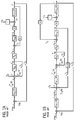
- FIGS. 1A and 1B illustrate such torque regulated (1A) and speed regulated (IB) tension controls, respectively.
- the toque regulated tension control technique consists of a torque current loop and a tension loop, while the speed regulated tension control technique not only has a torque current loop and a tension control loop, but also has an intermediate speed loop cascaded into the tension loop. From FIG.
- F * is the given tension
- F is the actual tension
- ⁇ m ′ is the actual speed of the main motor
- ⁇ m is the actual speed of the winder
- G PI_F ( z ) is the PID of the tension loop
- i sq is the torque producing current
- K a is the proportionality coefficient between electromagnetic torque and torque current
- K F is the tension constant in kN ⁇ s/m
- T m is the motor torque
- G ⁇ m T is the transfer function between speed and torque
- R is the real-time diameter of the winder
- T L is the load torque
- G F ⁇ v is the dynamic transfer function of tension
- ⁇ n is the natural frequency
- J is the rotational inertia of the winding block
- r is the radius of the main motor
- ⁇ v is a velocity difference between a speed near the main motor and a speed near the secondary motor.
- F * is the given tension
- F is the actual tension
- ⁇ m ⁇ is the given speed of the winder
- ⁇ m is the actual speed of the winder
- G PI_F ( z ) is the PID of the tension loop
- ⁇ m ′ is the actual speed of the main motor
- ⁇ m ( k ) is the sampling speed of the winder
- G PI_ ⁇ ( z ) is the PID of speed loop
- i sq is the torque producing current
- K a is the proportionality coefficient between electromagnetic torque and torque current
- K F is the tension constant in kN ⁇ s/m
- T m is the motor torque
- G ⁇ m T is the transfer function between speed and torque
- J is the rotational inertia of the winding block
- R is the real-time diameter of the winder
- T L is the load torque
- G F ⁇ v is the dynamic transfer function of tension
- G d is the delay of speed sampling
- r is the
- a system and a method as set forth in claims 1 and 11 are provided. Further embodiments are inter alia disclosed in the dependent claims.
- a control system for controlling operation of a main drive unit and a secondary drive unit in a web winder system to provide tension control of a continuous material web as it is translated between an unwinder and winder of the web winder system is provided.
- the control system includes a processor programmed to cause the main drive unit to operate in a velocity mode to set a linear velocity of the continuous material web, receive inputs from tension and speed detectors in the web winder system that detect a tension in and a speed of the continuous material web, and cause the secondary drive unit to operate in a modified torque regulated closed-loop tension control mode so as to control a tension in the web material.
- the processor is further programmed to cause the secondary drive unit to operate according to a torque regulated closed-loop tension control mode, based on inputs from the tension detectors and integrate a speed feedback loop into the torque regulated closed-loop tension control mode, via inputs from the speed detectors, so as to introduce active damping into the tension control.
- a web handling system for controlling tension in a web material includes a winder and unwinder between which a web material is transferred and a main drive unit comprising a first electric motor and first adjustable speed drive, the first electric motor and first adjustable speed drive rotationally driving guide rollers to translate the web material from the unwinder to the winder.
- the web handling system also includes a secondary drive unit comprising a second electric motor and second adjustable speed drive, the second electric motor and second adjustable speed drive rotationally driving the winder to roll the web material onto the winder.
- the web handling system further includes tension and speed detectors to detect a tension in and a speed of the web material between the unwinder and the winder and a control device to control operation of the main drive unit and the secondary drive unit to rotationally drive the guide rollers and the winder, respectively, at desired rotational speeds
- the control device is configured to cause the main drive unit to operate in a velocity mode to set a linear velocity of the web material cause the secondary drive unit to operate in a torque regulated closed-loop tension control mode, via inputs from the tension detectors, so as to control a tension in the web material, and integrate a speed feedback loop into the torque regulated closed-loop tension control mode, via inputs from the speed detectors, so as to introduce active damping into the tension control.
- a method of controlling tension control in a continuous material web translated between an unwinder and a winder in a web winder is defined according to the claim 11.
- Embodiments of the invention relate to a system and method for controlling tension in a continuous material web and, more particularly, to a system and method for controlling tension in a continuous material web in which the system damping is improved and thus better tension responses are achieved.
- Main and secondary drive units in the web winding system are operated in a velocity mode and a modified torque regulated closed-loop tension control mode, respectively, with a speed feedback loop being integrated into the torque regulated closed-loop tension control mode to improve system damping and achieve faster response time in controlling the tension in the continuous material web.
- FIG. 2 is a diagram showing a system 10 for winding and unwinding a product film or web material, i.e., a "web winder system,” with such winding and unwinding being performed in a tightness-controlled manner to ensure integrity of the web material 12.
- the system of FIG. 2 may be, for example, a post-processing apparatus for paper, such as a calendar/presser, printer, or any other processing apparatus for a continuous material web, wherein the material 12 is unwound from one roll and wound onto one or more other rolls during such post-processing.
- FIG. 2 shows an unwinder 14, in which a machine reel or roll 16 of web material 12 is placed, with the web material being unwound from the roll 16 and provided to a machine reel or roll 18 on a winder 20 (i.e., "rewinder") in the system 10.
- each of the unwinder 14 and winder 20 includes a respective drive unit 22, 24 comprised of an electric motor 26, 28 (e.g., AC induction motor) that is controlled by a motor drive 30, 32, such as an adjustable speed drive (ASD.
- the motor drives 30, 32 allow for dynamic control of the motors 26, 28 to control movement of the web material 12 between the unwinder 14 and winder 20.
- a main drive unit 34 is also included in system 10 that is positioned between unwinder 14 and winder 20.
- the main drive unit 34 includes an electric motor 36 (e.g., AC induction motor) that is controlled by a motor drive 38, such as an ASD.
- the main drive unit 34 operates to rotationally drive two nip rolls or rollers 40 that apply a force therebetween to generate a frictional tension along the web material 12 proportional to the force and the coefficient of friction between the material and the nip surface.
- FIG. 2 also shows a control system or device 42 that is operably connected to each of the drive units 22, 24, 34 (i.e., to the motor drives 30, 32, 38) and also to speed and tension sensors 44 positioned at various points along web material 12.
- the control system 42 provides control information to the motor drives 30, 32, 38, which control the respective motors 26, 28, 36 on the basis of the control information to provide a desired web speed and web tightness, for instance.
- the control system 42 may be provided as a PI controller or PID controller, according to embodiments of the invention, that includes a processor 46 therein for executing commands to implement the desired control.
- the control system 42 implements a torque regulated tension control scheme with active damping to control tension in the web material 12.
- the torque regulated tension control with the added active damping provides for a higher crossover frequency of the PI tension controller loop as compared to previously used torque regulated tension control techniques, so as to provide improved/faster tension responses in the system 10 and thereby further improve the dynamic performance of the system.
- K F is the tension constant in kN ⁇ s/m
- v 1 represents the linear velocity at which the primary volume core axis winds the coiled material
- v 2 represents the linear velocity at which the transport wheel sends out the coiled material
- ⁇ 1 represents the real-time angular velocity of the primary volume
- R 10 represents the radius of the primary volume core axis
- R 1 represents the real-time radius of the winding
- F 1 represents the tension that applies to the primary volume core axis and the coiled material
- J is the rotational inertia of the winding block
- M 1 is the equivalent drive torque which applies to the winding block
- M F 1 is the mechanical friction torque which applies to the wingding block.
- the control system 42 operates to set the linear velocity of the web process application via controlling of the main drive unit 34 working in a velocity mode, with the main drive unit 34 acting as a master drive in the system 10.
- the winder 20 and its associated secondary drive unit 22 acts as a slave drive operating in the torque closed-loop tension control mode.
- F * is the given tension
- F is the actual tension
- ⁇ m is the actual speed of the winder
- G PI_F ( s ) is the PID of the tension loop
- i sq is the torque producing current
- K a is the proportionality coefficient between electromagnetic torque and torque current
- K F is the tension coefficient
- K i_F and K z are tension PI coefficients
- T m is the motor torque
- G ⁇ m T is the transfer function between speed and torque
- R is the real-time diameter of the winder
- J is the rotational inertia of the winding block
- T L is the load torque
- G F ⁇ v is the dynamic transfer function of tension
- ⁇ n is the natural frequency
- ⁇ is the damping factor
- r is the radius of the main motor
- ⁇ v is a velocity difference between a speed near the main motor and a speed near the secondary motor.
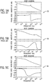
- FIGS. 5A-5C illustrate Bode diagrams 52, 54, 56 for a prior art torque regulated tension control technique ( FIG. 5A ), a prior art speed regulated tension control technique ( FIG. 5B ), and an exemplary torque regulated tension control technique with active damping ( FIG. 5C ).
- the crossover frequency of the proposed tension loop defined in FIG. 5C is larger than those provided in FIGS. 5A and 5B , with a much improved dynamic performance being achieved.
- FIGS. 6A-6C tension step response diagrams 58, 60, 62 are illustrated for a prior art torque regulated tension control technique ( FIG. 6A ), a prior art speed regulated tension control technique ( FIG. 6B ), and an exemplary torque regulated tension control technique with active damping ( FIG. 6C ).
- FIG. 6A the step response of the torque regulated tension control
- FIG. 6C the tension system step response time is significantly faster than those in FIG. 6A and FIG. 6B .
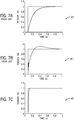
- the main/master drive unit 34 is in the velocity mode and the secondary/slave drive unit 22 is in closed tension loop, applying different tension control methods - i.e., a prior art torque regulated tension control technique, a prior art speed regulated tension control technique, and an exemplary torque regulated tension control technique with active damping.
- tension control method i.e., a prior art torque regulated tension control technique, a prior art speed regulated tension control technique, and an exemplary torque regulated tension control technique with active damping.
- FIGS. 7A-7C The corresponding simulation results are depicted in FIGS. 7A-7C , with tension control step responses 64, 66, 68 being illustrated for the prior art torque regulated tension control technique ( FIG. 7A ), the prior art speed regulated tension control technique ( FIG. 7B ), and the exemplary torque regulated tension control technique with active damping ( FIG. 7C ). It can be seen in FIGS. 7A-7C that the proposed torque mode of closed loop tension control with active damping has the best dynamic performance with superior
- FIGS. 8A-8C illustrate the disturbance rejection capability of each of the different tension control methods, with tension control step responses 70, 72, 74 being illustrated for the prior art torque regulated tension control technique ( FIG. 8A ), the prior art speed regulated tension control technique ( FIG. 8B ), and the exemplary torque regulated tension control technique with active damping ( FIG. 8C ). It can be seen in FIGS. 8A-8C that the proposed torque mode of closed loop tension control with active damping eliminates the tension system oscillation completely when a velocity disturbance is introduced onto the web material.
- embodiments of the invention thus provide a torque regulated tension control with active damping that is accomplished by introducing an additional speed feedback loop to a torque regulated tension control.
- Introduction of the speed feedback loop enables the web winding system to achieve large system natural frequency and damping, thereby increasing system responsiveness in controlling tension in the web material in a dynamic fashion.
- a technical contribution of embodiments of the present invention is that a computer implemented technique is provided for torque regulated tension control with active damping.
- a control system for controlling operation of a main drive unit and a secondary drive unit in a web winder system to provide tension control of a continuous material web as it is translated between an unwinder and winder of the web winder system.
- the control system includes a processor programmed to cause the main drive unit to operate in a velocity mode to set a linear velocity of the continuous material web, receive inputs from tension and speed detectors in the web winder system that detect a tension in and a speed of the continuous material web, and cause the secondary drive unit to operate in a modified torque regulated closed-loop tension control mode so as to control a tension in the web material.
- the processor is further programmed to cause the secondary drive unit to operate according to a torque regulated closed-loop tension control mode, based on inputs from the tension detectors and integrate a speed feedback loop into the torque regulated closed-loop tension control mode, via inputs from the speed detectors, so as to introduce active damping into the tension control.
- web handling system for controlling tension in a web material includes a winder and unwinder between which a web material is transferred and a main drive unit comprising a first electric motor and first adjustable speed drive, the first electric motor and first adjustable speed drive rotationally driving guide rollers to translate the web material from the unwinder to the winder.
- the web handling system also includes a secondary drive unit comprising a second electric motor and second adjustable speed drive, the second electric motor and second adjustable speed drive rotationally driving the winder to roll the web material onto the winder.
- the web handling system further includes tension and speed detectors to detect a tension in and a speed of the web material between the unwinder and the winder and a control device to control operation of the main drive unit and the secondary drive unit to rotationally drive the guide rollers and the winder, respectively, at desired rotational speeds, wherein, in controlling operation of the main drive unit and the secondary drive unit to rotationally drive the guide rollers and the winder at desired rotational speeds, the control device is configured to cause the main drive unit to operate in a velocity mode to set a linear velocity of the web material cause the secondary drive unit to operate in a modified torque regulated closed-loop tension control mode, via inputs from the tension detectors, so as to control a tension in the web material, and integrate a speed feedback loop into the torque regulated closed-loop tension control mode, via inputs from the speed detectors, so as to introduce active damping into the tension control.
Landscapes
- Controlling Rewinding, Feeding, Winding, Or Abnormalities Of Webs (AREA)
Claims (13)
- Steuersystem (42) zum Steuern des Betriebs einer Hauptantriebseinheit (34) und einer Sekundärantriebseinheit (22) in einem Bahnwickelsystem (10) zum Vorsehen einer Steuerung der Spannung einer kontinuierlichen Materialbahn (12), wenn sie zwischen einem Abwicklungsgerät (14) und einem Aufwicklungsgerät (20) des Bahnwickelsystems (10) übertragen wird, wobei das Steuersystem einen Prozessor (46) hat, der programmiert ist zum:Veranlassen, dass die Hauptantriebseinheit (34) in einem Geschwindigkeitsmodus arbeitet, um eine Lineargeschwindigkeit der kontinuierlichen Materialbahn (12) einzustellen;Empfangen von Impulsen von Spannungs- und Geschwindigkeitsdetektoren (44) in dem Bahnwickelsystem (10), die eine Spannung undeine Geschwindigkeit der kontinuierlichen Materialbahn (12) detektieren; undVeranlassen, dass die sekundäre Antriebseinheit (22) in einem modifizierten drehmomentgeregelten Spannungsregelungsmodus arbeitet, um eine Spannung in der kontinuierlichen Materialbahn (12) zu steuern, wobei das Arbeiten in dem modifizierten drehmomentgeregelten Spannungsregelungsmodus Folgendes aufweist:Veranlassen der Sekundärantriebseinheit (22), dass diese gemäß einem drehmomentgeregelten Spannungsregelungsmodus arbeitet, und zwar basierend auf Eingangsgrößen von den Spannungsdetektoren (46); undIntegrieren einer Geschwindigkeitsrückkoppelungsschleife in den drehmomentgeregelten Spannungsregelungsmodus über Eingangsgrößen von den Geschwindigkeitsdetektoren (44), um eine aktive Dämpfung in die Steuerung der Spannung einzuführen.
- Steuersystem (42) nach Anspruch 1, wobei der Prozessor (46) so programmiert ist, dass er bewirkt, dass die sekundäre Antriebseinheit (22) in einem modifizierten drehmomentgeregelten Spannungsregelungsmodus gemäß einer Closed-Loop- bzw. Regelungstransferfunktion arbeitet, die, wie folgt, definiert ist:

wobei Ft die tatsächliche Spannung ist, wobei ωm die tatsächliche Drehzahl bzw. Geschwindigkeit des Aufwicklungsgerätes (20) ist, wobei Ka der Proportionalitätskoeffizient zwischen dem elektromagnetischen Drehmoment und dem Drehmomentstrom ist, wobei KF der Spannungskoeffizient ist, wobei Gωm T die Transferfunktion zwischen Geschwindigkeit und Drehmoment ist, wobei G FΔv die dynamische Transferfunktion der Spannung ist, wobei R der Echtzeitdurchmesser des Aufwicklungsgerätes (20) ist, wobei J die Drehträgheit bzw. das Trägheitsmoment des Wicklungsblocks ist, wobei s ein Drehzahl- bzw. Geschwindigkeitsausdruck erster Ordnung ist. - Steuersystem (42) nach Anspruch 1, wobei der Prozessor (46) programmiert ist, die zweite Antriebseinheit (22) zu veranlassen in einem modifizierten drehmomentgeregelten Spannungsregelungsmodus gemäß einer Open-Loop- bzw. Steuerungstransferfunktion zu arbeiten, die, wie folgt, definiert ist:

- Steuersystem (42) nach Anspruch 3, wobei ein Paar von dominanten Polen in der Open-Loop- bzw. Steuerungstransferfunktion eine Lage hat, die, wie folgt, definiert ist:

- Steuersystem (42) nach Anspruch 1, wobei der Prozessor (46) so programmiert ist, dass er eine Crossover- bzw. Übergangsfrequenz des drehmomentgeregelten Spannungsregelungsmodus basierend auf der Integration der Geschwindigkeitsrückkoppelungsschleife erhöht.
- Steuersystem (42) nach Anspruch 1, wobei der Prozessor (46) so programmiert ist, dass er eine Spannungsoszillation während einer Geschwindigkeitsstörung der kontinuierlichen Materialbahn (12) basierend auf der Integration der Geschwindigkeitsrückkoppelungsschleife in den drehmomentgeregelten Spannungsregelungsmodus eliminiert.
- Steuersystem (42) nach Anspruch 1, wobei der Prozessor (46) programmiert ist, um zu bewirken, dass die Hauptantriebseinheit (34) als eine Master-Antriebseinheit arbeitet und die sekundäre Antriebseinheit (22) als eine Slave-Antriebseinheit arbeitet.
- Steuersystem (42) nach Anspruch 1, wobei das Steuersystem (42) in einem Bahnwickelsystem (10) implementiert ist, welches Folgendes aufweist:ein Aufwicklungsgerät (20) und ein Abwicklungsgerät (14) zwischen denen eine kontinuierliche Materialbahn (12) übertragen wird;eine Hauptantriebseinheit (34), welche einen ersten Elektromotor (36) undeinen ersten Antrieb (38) mit einstellbarer Drehzahl aufweist, wobei der erste Elektromotor (36) und der erste Antrieb (38) mit einstellbarer Drehzahl Führungsrollen (40) zur Drehung antreiben, um die kontinuierliche Materialbahn (12) von dem Abwicklungsgerät (14) zu dem Aufwicklungsgerät (20) zu übertragen;eine sekundäre Antriebseinheit (22), welche einen zweiten Elektromotor (26) und einen zweiten Antrieb (30) mit einstellbarer Drehzahl aufweist, wobei der zweite Elektromotor (26) und der zweite Antrieb (30) mit einstellbarer Drehzahl das Aufwicklungsgerät (20) zur Drehung antreiben, um die kontinuierliche Materialbahn (12) auf das Aufwicklungsgerät (20) zu rollen; undSpannungs- und Geschwindigkeitsdetektoren (44) zum Detektieren einer Spannung und einer Geschwindigkeit der kontinuierlichen Materialbahn (12) zwischen dem Abwicklungsgerät (14) und dem Aufwicklungsgerät (20).
- Steuersystem (42) nach Anspruch 8, wobei das Bahnwickelsystem (10) weiter eine zusätzliche Antriebseinheit aufweist, die einen dritten Elektromotor (28) und einen dritten Antrieb (32) mit einstellbarer Drehzahl aufweist, wobei der dritte Elektromotor (28) und der dritte Antrieb (32) mit einstellbarer Drehzahl das Abwicklungsgerät (14) zur Drehung antreiben, um das Bahnmaterial (12) abzuwickeln.
- Steuersystem (42) nach Anspruch 1, wobei der Prozessor (46) in eine Proportional-Integral- bzw. PI-Steuervorrichtung integriert ist.
- Verfahren zum Steuern einer Spannungsregelung in einer kontinuierlichen Materialbahn (12), die zwischen einem Abwicklungsgerät (14) und einem Aufwicklungsgerät (20) in einem Bahnwickelsystem (10) übertragen wird, wobei das Verfahren Folgendes aufweist:Steuern einer Hauptantriebseinheit (34) des Bahnwickelsystems (10), so dass diese in einem Geschwindigkeitsmodus arbeitet, um eine Lineargeschwindigkeit der kontinuierlichen Materialbahn (12) einzustellen; undSteuern einer sekundären Antriebseinheit (22) des Bahnwickelsystems (10), so dass diese in einem modifizierten drehmomentgeregelten Spannungsregelungsmodus arbeitet, um eine Spannung in dem Bahnmaterial (12) zu steuern;wobei bei der Steuerung der sekundären Antriebseinheit (22) der modifizierte drehmomentgeregelte Spannungsregelungsmodus eine Drehmomentstromschleife, eine Spannungsschleife und eine Drehzahl- bzw. Geschwindigkeitsrückkoppelungsschleife aufweist, um die Spannung in dem Bahnmaterial (12) zu steuern; undwobei das Steuern der sekundären Antriebseinheit (22) des Bahnwickelsystems (10), so dass dieses in dem modifizierten drehmomentgeregelten Spannungsregelungsmodus arbeitet, weiter Folgendes aufweist:Empfangen von Eingangsgrößen von Spannungs- und Geschwindigkeitsdetektoren (44) in dem Bahnwickelsystem (10), die eine Spannung und eine Geschwindigkeit der kontinuierlichen Materialbahn (12) detektieren;Veranlassen der sekundären Antriebseinheit (22), dass diese in einem drehmomentgeregelten Spannungsregelungsmodus arbeitet, der die Drehmomentstromschleife und die Spannungsschleife aufweist, über Eingangsgrößen von den Spannungsdetektoren (44), um eine Spannung in dem Bahnmaterial (12) zu steuern, undIntegrieren der Geschwindigkeitsrückkoppelungsschleife in den drehmomentgeregelten Spannungsregelungsmodus über Eingangsgrößen von den Geschwindigkeitsdetektoren (44), um eine aktive Dämpfung in die Spannungssteuerung einzuführen.
- Verfahren nach Anspruch 11, wobei der modifizierte drehmomentgeregelten Spannungsregelungsmodus als eine Closed-Loop- bzw. Regelungstransferfunktion gemäß Forlgendem definiert ist:

m T die Transferfunktion zwischen Geschwindigkeit und Drehmoment ist, wobei G FΔ v die dynamische Transferfunktion der Spannung ist, wobei R der Echtzeitdurchmesser des Aufwicklungsgerätes (20) ist, wobei J die Drehträgheit bzw. das Trägheitsmoment des Wicklungsblocks ist, wobei s ein Drehzahl- bzw. Geschwindigkeitsausdruck erster Ordnung ist. - Verfahren nach Anspruch 11, wobei der modifizierte drehmomentgeregelten Spannungsregelungsmodus als eine Open-Loop- bzw. Steuerungstransferfunktion gemäß Folgendem definiert ist:

Applications Claiming Priority (1)
| Application Number | Priority Date | Filing Date | Title |
|---|---|---|---|
| US15/435,549 US10377598B2 (en) | 2017-02-17 | 2017-02-17 | Dynamic performance and active damping methods in web winder tension control systems |
Publications (2)
| Publication Number | Publication Date |
|---|---|
| EP3363755A1 EP3363755A1 (de) | 2018-08-22 |
| EP3363755B1 true EP3363755B1 (de) | 2020-06-03 |
Family
ID=61198705
Family Applications (1)
| Application Number | Title | Priority Date | Filing Date |
|---|---|---|---|
| EP18156194.5A Active EP3363755B1 (de) | 2017-02-17 | 2018-02-09 | Dynamische leistungs- und aktive dämpfungsverfahren in bahnwicklungsspannungsregelungssystemen |
Country Status (2)
| Country | Link |
|---|---|
| US (1) | US10377598B2 (de) |
| EP (1) | EP3363755B1 (de) |
Families Citing this family (8)
| Publication number | Priority date | Publication date | Assignee | Title |
|---|---|---|---|---|
| WO2020026620A1 (ja) * | 2018-08-02 | 2020-02-06 | トタニ技研工業株式会社 | 間欠搬送装置 |
| CN109739292A (zh) * | 2019-01-23 | 2019-05-10 | 济南大学 | 光伏系统mppt模糊自抗扰控制方法、控制器及系统 |
| CN113183440B (zh) * | 2021-04-28 | 2023-01-24 | 重庆科技学院 | 一种丁基胶减振阻尼带生产线及张力控制方法 |
| CN116534644A (zh) * | 2023-04-23 | 2023-08-04 | 山西太钢不锈钢精密带钢有限公司 | 基于模糊pid的超薄不锈精密带钢卷取张力控制方法 |
| CN116618448B (zh) * | 2023-06-27 | 2026-02-06 | 鞍钢集团北京研究院有限公司 | 一种单机架可逆轧机卷取张力自适应控制方法及系统 |
| CN116902657B (zh) * | 2023-09-13 | 2023-11-21 | 深圳市阿尔斯自动化科技有限公司 | 一种模切分条机的电气控制系统及控制方法 |
| TWI876721B (zh) * | 2023-11-30 | 2025-03-11 | 財團法人金屬工業研究發展中心 | 串級控制捲繞系統 |
| CN120841281B (zh) * | 2025-09-22 | 2026-01-06 | 福州印团网印刷有限公司 | 高速输纸机构纸张张力动态平衡控制方法及系统 |
Family Cites Families (17)
| Publication number | Priority date | Publication date | Assignee | Title |
|---|---|---|---|---|
| US3829745A (en) * | 1973-02-02 | 1974-08-13 | Xerox Corp | Techniques for maintaining substantially constant tension in web |
| US4151594A (en) * | 1976-02-26 | 1979-04-24 | Bobst-Champlain, Inc. | Web tension control for high-speed web handling equipment |
| US4448366A (en) * | 1982-07-08 | 1984-05-15 | Westinghouse Electric Corp. | Coil diameter tracking system and tension regulation system using such tracking system |
| JP2774768B2 (ja) | 1994-03-14 | 1998-07-09 | 三菱電機株式会社 | ルーパの張力制御装置 |
| EP0745890A1 (de) * | 1995-05-30 | 1996-12-04 | Eastman Kodak Company | Bewegungssteuerungssystem für Filmband |
| US6047275A (en) | 1997-10-14 | 2000-04-04 | Allen-Bradley Company, Llc | Fuzzy logic winder analyzer |
| US6314333B1 (en) * | 1998-07-03 | 2001-11-06 | Kimberly-Clark Worldwide, Inc. | Method and apparatus for controlling web tension by actively controlling velocity and acceleration of a dancer roll |
| DE19923204B4 (de) * | 1999-05-20 | 2004-04-29 | Man Roland Druckmaschinen Ag | Drehzahl-Regelanordnung für eine Abwickeleinrichtung |
| US6845282B2 (en) * | 2002-09-04 | 2005-01-18 | The Procter & Gamble Company | Method of controlling tension in a web |
| DE102004006232B3 (de) * | 2004-02-09 | 2005-07-21 | Koenig & Bauer Ag | Verfahren und Vorrichtung zum Einziehen einer Materialbahn |
| US7092781B2 (en) * | 2004-12-10 | 2006-08-15 | The Procter & Gamble Company | Method of controlling tension in a web |
| JP5481795B2 (ja) | 2008-03-26 | 2014-04-23 | Jfeスチール株式会社 | ルーパー設備 |
| KR101512175B1 (ko) | 2013-03-27 | 2015-04-23 | (주)프로템 | 서보모터 멀티 제어 장치 |
| JP6165332B2 (ja) * | 2014-05-23 | 2017-07-19 | 三菱電機株式会社 | ロール間搬送制御装置 |
| US10315876B2 (en) * | 2014-11-27 | 2019-06-11 | Mitsubishi Electric Corporation | Roller-to-roller conveyance control apparatus |
| US9925807B2 (en) * | 2015-09-30 | 2018-03-27 | Brother Kogyo Kabushiki Kaisha | Conveyance system, sheet processing system, and controller |
| JP6913488B2 (ja) * | 2017-03-21 | 2021-08-04 | 株式会社Screenホールディングス | 搬送制御方法及び搬送装置並びに印刷装置 |
-
2017
- 2017-02-17 US US15/435,549 patent/US10377598B2/en active Active
-
2018
- 2018-02-09 EP EP18156194.5A patent/EP3363755B1/de active Active
Non-Patent Citations (1)
| Title |
|---|
| None * |
Also Published As
| Publication number | Publication date |
|---|---|
| EP3363755A1 (de) | 2018-08-22 |
| US20180237249A1 (en) | 2018-08-23 |
| US10377598B2 (en) | 2019-08-13 |
Similar Documents
| Publication | Publication Date | Title |
|---|---|---|
| EP3363755B1 (de) | Dynamische leistungs- und aktive dämpfungsverfahren in bahnwicklungsspannungsregelungssystemen | |
| US10858215B2 (en) | Method for coiling a coiled product, control installation, computer software product, and coiling machine | |
| US4704171A (en) | Laminating device with paper tension control | |
| EP3988485B1 (de) | Parametrierung eines zugkraftreglers | |
| Raul et al. | Design and implementation of adaptive PI control schemes for web tension control in roll-to-roll (R2R) manufacturing | |
| CN116281334B (zh) | 一种卷材张力控制系统及控制方法 | |
| US20110246127A1 (en) | Method for Determining at Least One Controller Parameter of a Dancer Position Control Element | |
| JP2005506257A (ja) | フェスツーンの速度及び付勢力の能動制御によるウェブ張力の制御及びウェブの滞留 | |
| JPS58183554A (ja) | 材料の巻上げを制御する方法 | |
| CN110502043B (zh) | 幅材卷绕机张力控制系统中的动态性能和主动阻尼方法 | |
| Dwivedula et al. | Effect of backlash on web tension in roll-to-roll manufacturing systems: Mathematical model, mitigation method and experimental evaluation | |
| JP2604334B2 (ja) | ウエブ加工機 | |
| EP3378808B1 (de) | Verfahren zur steuerung des betriebs eines wicklers für eine faserbahn | |
| Allaoua et al. | Multi-drive paper system control based on multi-input multi-output PID controller | |
| EP1761447A1 (de) | Verfahren zur steuerung des windens einer rolle von bahnmaterial | |
| CN113518752A (zh) | 卷切割机的驱动 | |
| Seshadri et al. | Modeling and control of a rotating turret winder used in roll-to-roll manufacturing | |
| JP2000103556A (ja) | シート巻き戻し張力制御方法 | |
| JPS60262766A (ja) | スリツタの巻取駆動装置 | |
| Pagilla et al. | Robust controllers for large-scale interconnected systems: applications to web processing machines | |
| Kępski et al. | Tension Control: Open-Loop Torque Control in Material Unwinding Process | |
| JP2874736B2 (ja) | シート状物用スリッタの耳部巻取張力制御装置 | |
| KR101000826B1 (ko) | 고속 롤투롤 시스템의 펜듈럼 덴서를 사용한 장력제어 방법 | |
| Raul et al. | Web tension regulation with partially known periodic disturbances in roll-to-roll manufacturing systems | |
| JPH04280766A (ja) | シート状物用巻取機の巻取張力制御装置 |
Legal Events
| Date | Code | Title | Description |
|---|---|---|---|
| PUAI | Public reference made under article 153(3) epc to a published international application that has entered the european phase |
Free format text: ORIGINAL CODE: 0009012 |
|
| STAA | Information on the status of an ep patent application or granted ep patent |
Free format text: STATUS: REQUEST FOR EXAMINATION WAS MADE |
|
| 17P | Request for examination filed |
Effective date: 20180209 |
|
| AK | Designated contracting states |
Kind code of ref document: A1 Designated state(s): AL AT BE BG CH CY CZ DE DK EE ES FI FR GB GR HR HU IE IS IT LI LT LU LV MC MK MT NL NO PL PT RO RS SE SI SK SM TR |
|
| AX | Request for extension of the european patent |
Extension state: BA ME |
|
| RIN1 | Information on inventor provided before grant (corrected) |
Inventor name: YAO, WENXI Inventor name: LU, ZHENGYU Inventor name: CHEN, FAYI Inventor name: LI, HUAQIANG |
|
| RIC1 | Information provided on ipc code assigned before grant |
Ipc: B65H 23/18 20060101ALI20191212BHEP Ipc: B65H 23/195 20060101ALI20191212BHEP Ipc: B65H 23/10 20060101ALI20191212BHEP Ipc: B65H 23/04 20060101ALI20191212BHEP Ipc: B65H 23/06 20060101AFI20191212BHEP |
|
| GRAP | Despatch of communication of intention to grant a patent |
Free format text: ORIGINAL CODE: EPIDOSNIGR1 |
|
| STAA | Information on the status of an ep patent application or granted ep patent |
Free format text: STATUS: GRANT OF PATENT IS INTENDED |
|
| INTG | Intention to grant announced |
Effective date: 20200210 |
|
| GRAS | Grant fee paid |
Free format text: ORIGINAL CODE: EPIDOSNIGR3 |
|
| GRAA | (expected) grant |
Free format text: ORIGINAL CODE: 0009210 |
|
| STAA | Information on the status of an ep patent application or granted ep patent |
Free format text: STATUS: THE PATENT HAS BEEN GRANTED |
|
| AK | Designated contracting states |
Kind code of ref document: B1 Designated state(s): AL AT BE BG CH CY CZ DE DK EE ES FI FR GB GR HR HU IE IS IT LI LT LU LV MC MK MT NL NO PL PT RO RS SE SI SK SM TR |
|
| REG | Reference to a national code |
Ref country code: GB Ref legal event code: FG4D |
|
| REG | Reference to a national code |
Ref country code: AT Ref legal event code: REF Ref document number: 1276806 Country of ref document: AT Kind code of ref document: T Effective date: 20200615 Ref country code: CH Ref legal event code: EP |
|
| REG | Reference to a national code |
Ref country code: DE Ref legal event code: R096 Ref document number: 602018004958 Country of ref document: DE |
|
| REG | Reference to a national code |
Ref country code: LT Ref legal event code: MG4D |
|
| PG25 | Lapsed in a contracting state [announced via postgrant information from national office to epo] |
Ref country code: LT Free format text: LAPSE BECAUSE OF FAILURE TO SUBMIT A TRANSLATION OF THE DESCRIPTION OR TO PAY THE FEE WITHIN THE PRESCRIBED TIME-LIMIT Effective date: 20200603 Ref country code: GR Free format text: LAPSE BECAUSE OF FAILURE TO SUBMIT A TRANSLATION OF THE DESCRIPTION OR TO PAY THE FEE WITHIN THE PRESCRIBED TIME-LIMIT Effective date: 20200904 Ref country code: SE Free format text: LAPSE BECAUSE OF FAILURE TO SUBMIT A TRANSLATION OF THE DESCRIPTION OR TO PAY THE FEE WITHIN THE PRESCRIBED TIME-LIMIT Effective date: 20200603 Ref country code: NO Free format text: LAPSE BECAUSE OF FAILURE TO SUBMIT A TRANSLATION OF THE DESCRIPTION OR TO PAY THE FEE WITHIN THE PRESCRIBED TIME-LIMIT Effective date: 20200903 Ref country code: FI Free format text: LAPSE BECAUSE OF FAILURE TO SUBMIT A TRANSLATION OF THE DESCRIPTION OR TO PAY THE FEE WITHIN THE PRESCRIBED TIME-LIMIT Effective date: 20200603 |
|
| REG | Reference to a national code |
Ref country code: NL Ref legal event code: MP Effective date: 20200603 |
|
| PG25 | Lapsed in a contracting state [announced via postgrant information from national office to epo] |
Ref country code: RS Free format text: LAPSE BECAUSE OF FAILURE TO SUBMIT A TRANSLATION OF THE DESCRIPTION OR TO PAY THE FEE WITHIN THE PRESCRIBED TIME-LIMIT Effective date: 20200603 Ref country code: LV Free format text: LAPSE BECAUSE OF FAILURE TO SUBMIT A TRANSLATION OF THE DESCRIPTION OR TO PAY THE FEE WITHIN THE PRESCRIBED TIME-LIMIT Effective date: 20200603 Ref country code: HR Free format text: LAPSE BECAUSE OF FAILURE TO SUBMIT A TRANSLATION OF THE DESCRIPTION OR TO PAY THE FEE WITHIN THE PRESCRIBED TIME-LIMIT Effective date: 20200603 Ref country code: BG Free format text: LAPSE BECAUSE OF FAILURE TO SUBMIT A TRANSLATION OF THE DESCRIPTION OR TO PAY THE FEE WITHIN THE PRESCRIBED TIME-LIMIT Effective date: 20200903 |
|
| REG | Reference to a national code |
Ref country code: AT Ref legal event code: MK05 Ref document number: 1276806 Country of ref document: AT Kind code of ref document: T Effective date: 20200603 |
|
| PG25 | Lapsed in a contracting state [announced via postgrant information from national office to epo] |
Ref country code: NL Free format text: LAPSE BECAUSE OF FAILURE TO SUBMIT A TRANSLATION OF THE DESCRIPTION OR TO PAY THE FEE WITHIN THE PRESCRIBED TIME-LIMIT Effective date: 20200603 Ref country code: AL Free format text: LAPSE BECAUSE OF FAILURE TO SUBMIT A TRANSLATION OF THE DESCRIPTION OR TO PAY THE FEE WITHIN THE PRESCRIBED TIME-LIMIT Effective date: 20200603 |
|
| PG25 | Lapsed in a contracting state [announced via postgrant information from national office to epo] |
Ref country code: RO Free format text: LAPSE BECAUSE OF FAILURE TO SUBMIT A TRANSLATION OF THE DESCRIPTION OR TO PAY THE FEE WITHIN THE PRESCRIBED TIME-LIMIT Effective date: 20200603 Ref country code: ES Free format text: LAPSE BECAUSE OF FAILURE TO SUBMIT A TRANSLATION OF THE DESCRIPTION OR TO PAY THE FEE WITHIN THE PRESCRIBED TIME-LIMIT Effective date: 20200603 Ref country code: IT Free format text: LAPSE BECAUSE OF FAILURE TO SUBMIT A TRANSLATION OF THE DESCRIPTION OR TO PAY THE FEE WITHIN THE PRESCRIBED TIME-LIMIT Effective date: 20200603 Ref country code: CZ Free format text: LAPSE BECAUSE OF FAILURE TO SUBMIT A TRANSLATION OF THE DESCRIPTION OR TO PAY THE FEE WITHIN THE PRESCRIBED TIME-LIMIT Effective date: 20200603 Ref country code: PT Free format text: LAPSE BECAUSE OF FAILURE TO SUBMIT A TRANSLATION OF THE DESCRIPTION OR TO PAY THE FEE WITHIN THE PRESCRIBED TIME-LIMIT Effective date: 20201006 Ref country code: SM Free format text: LAPSE BECAUSE OF FAILURE TO SUBMIT A TRANSLATION OF THE DESCRIPTION OR TO PAY THE FEE WITHIN THE PRESCRIBED TIME-LIMIT Effective date: 20200603 Ref country code: AT Free format text: LAPSE BECAUSE OF FAILURE TO SUBMIT A TRANSLATION OF THE DESCRIPTION OR TO PAY THE FEE WITHIN THE PRESCRIBED TIME-LIMIT Effective date: 20200603 Ref country code: EE Free format text: LAPSE BECAUSE OF FAILURE TO SUBMIT A TRANSLATION OF THE DESCRIPTION OR TO PAY THE FEE WITHIN THE PRESCRIBED TIME-LIMIT Effective date: 20200603 |
|
| PG25 | Lapsed in a contracting state [announced via postgrant information from national office to epo] |
Ref country code: IS Free format text: LAPSE BECAUSE OF FAILURE TO SUBMIT A TRANSLATION OF THE DESCRIPTION OR TO PAY THE FEE WITHIN THE PRESCRIBED TIME-LIMIT Effective date: 20201003 Ref country code: SK Free format text: LAPSE BECAUSE OF FAILURE TO SUBMIT A TRANSLATION OF THE DESCRIPTION OR TO PAY THE FEE WITHIN THE PRESCRIBED TIME-LIMIT Effective date: 20200603 Ref country code: PL Free format text: LAPSE BECAUSE OF FAILURE TO SUBMIT A TRANSLATION OF THE DESCRIPTION OR TO PAY THE FEE WITHIN THE PRESCRIBED TIME-LIMIT Effective date: 20200603 |
|
| REG | Reference to a national code |
Ref country code: DE Ref legal event code: R097 Ref document number: 602018004958 Country of ref document: DE |
|
| PLBE | No opposition filed within time limit |
Free format text: ORIGINAL CODE: 0009261 |
|
| STAA | Information on the status of an ep patent application or granted ep patent |
Free format text: STATUS: NO OPPOSITION FILED WITHIN TIME LIMIT |
|
| PG25 | Lapsed in a contracting state [announced via postgrant information from national office to epo] |
Ref country code: DK Free format text: LAPSE BECAUSE OF FAILURE TO SUBMIT A TRANSLATION OF THE DESCRIPTION OR TO PAY THE FEE WITHIN THE PRESCRIBED TIME-LIMIT Effective date: 20200603 |
|
| 26N | No opposition filed |
Effective date: 20210304 |
|
| PG25 | Lapsed in a contracting state [announced via postgrant information from national office to epo] |
Ref country code: SI Free format text: LAPSE BECAUSE OF FAILURE TO SUBMIT A TRANSLATION OF THE DESCRIPTION OR TO PAY THE FEE WITHIN THE PRESCRIBED TIME-LIMIT Effective date: 20200603 |
|
| PG25 | Lapsed in a contracting state [announced via postgrant information from national office to epo] |
Ref country code: MC Free format text: LAPSE BECAUSE OF FAILURE TO SUBMIT A TRANSLATION OF THE DESCRIPTION OR TO PAY THE FEE WITHIN THE PRESCRIBED TIME-LIMIT Effective date: 20200603 |
|
| REG | Reference to a national code |
Ref country code: BE Ref legal event code: MM Effective date: 20210228 |
|
| PG25 | Lapsed in a contracting state [announced via postgrant information from national office to epo] |
Ref country code: LU Free format text: LAPSE BECAUSE OF NON-PAYMENT OF DUE FEES Effective date: 20210209 Ref country code: LI Free format text: LAPSE BECAUSE OF NON-PAYMENT OF DUE FEES Effective date: 20210228 Ref country code: CH Free format text: LAPSE BECAUSE OF NON-PAYMENT OF DUE FEES Effective date: 20210228 |
|
| PG25 | Lapsed in a contracting state [announced via postgrant information from national office to epo] |
Ref country code: FR Free format text: LAPSE BECAUSE OF NON-PAYMENT OF DUE FEES Effective date: 20210228 Ref country code: IE Free format text: LAPSE BECAUSE OF NON-PAYMENT OF DUE FEES Effective date: 20210209 |
|
| PG25 | Lapsed in a contracting state [announced via postgrant information from national office to epo] |
Ref country code: BE Free format text: LAPSE BECAUSE OF NON-PAYMENT OF DUE FEES Effective date: 20210228 |
|
| GBPC | Gb: european patent ceased through non-payment of renewal fee |
Effective date: 20220209 |
|
| PG25 | Lapsed in a contracting state [announced via postgrant information from national office to epo] |
Ref country code: GB Free format text: LAPSE BECAUSE OF NON-PAYMENT OF DUE FEES Effective date: 20220209 |
|
| P01 | Opt-out of the competence of the unified patent court (upc) registered |
Effective date: 20230521 |
|
| PG25 | Lapsed in a contracting state [announced via postgrant information from national office to epo] |
Ref country code: CY Free format text: LAPSE BECAUSE OF FAILURE TO SUBMIT A TRANSLATION OF THE DESCRIPTION OR TO PAY THE FEE WITHIN THE PRESCRIBED TIME-LIMIT Effective date: 20200603 |
|
| PG25 | Lapsed in a contracting state [announced via postgrant information from national office to epo] |
Ref country code: HU Free format text: LAPSE BECAUSE OF FAILURE TO SUBMIT A TRANSLATION OF THE DESCRIPTION OR TO PAY THE FEE WITHIN THE PRESCRIBED TIME-LIMIT; INVALID AB INITIO Effective date: 20180209 |
|
| PG25 | Lapsed in a contracting state [announced via postgrant information from national office to epo] |
Ref country code: MK Free format text: LAPSE BECAUSE OF FAILURE TO SUBMIT A TRANSLATION OF THE DESCRIPTION OR TO PAY THE FEE WITHIN THE PRESCRIBED TIME-LIMIT Effective date: 20200603 |
|
| PG25 | Lapsed in a contracting state [announced via postgrant information from national office to epo] |
Ref country code: MT Free format text: LAPSE BECAUSE OF FAILURE TO SUBMIT A TRANSLATION OF THE DESCRIPTION OR TO PAY THE FEE WITHIN THE PRESCRIBED TIME-LIMIT Effective date: 20200603 |
|
| PGFP | Annual fee paid to national office [announced via postgrant information from national office to epo] |
Ref country code: DE Payment date: 20250122 Year of fee payment: 8 |
|
| PG25 | Lapsed in a contracting state [announced via postgrant information from national office to epo] |
Ref country code: TR Free format text: LAPSE BECAUSE OF FAILURE TO SUBMIT A TRANSLATION OF THE DESCRIPTION OR TO PAY THE FEE WITHIN THE PRESCRIBED TIME-LIMIT Effective date: 20200603 |