EP3363618A1 - Stationary hot-stamping head, stamping unit with stationary hot-stamping head and method for applying a cover material onto an object - Google Patents
Stationary hot-stamping head, stamping unit with stationary hot-stamping head and method for applying a cover material onto an object Download PDFInfo
- Publication number
- EP3363618A1 EP3363618A1 EP17157240.7A EP17157240A EP3363618A1 EP 3363618 A1 EP3363618 A1 EP 3363618A1 EP 17157240 A EP17157240 A EP 17157240A EP 3363618 A1 EP3363618 A1 EP 3363618A1
- Authority
- EP
- European Patent Office
- Prior art keywords
- covering material
- application head
- unit
- application
- roller element
- Prior art date
- Legal status (The legal status is an assumption and is not a legal conclusion. Google has not performed a legal analysis and makes no representation as to the accuracy of the status listed.)
- Granted
Links
Images


Classifications
-
- B—PERFORMING OPERATIONS; TRANSPORTING
- B44—DECORATIVE ARTS
- B44C—PRODUCING DECORATIVE EFFECTS; MOSAICS; TARSIA WORK; PAPERHANGING
- B44C1/00—Processes, not specifically provided for elsewhere, for producing decorative surface effects
- B44C1/16—Processes, not specifically provided for elsewhere, for producing decorative surface effects for applying transfer pictures or the like
- B44C1/165—Processes, not specifically provided for elsewhere, for producing decorative surface effects for applying transfer pictures or the like for decalcomanias; sheet material therefor
- B44C1/17—Dry transfer
- B44C1/1712—Decalcomanias applied under heat and pressure, e.g. provided with a heat activable adhesive
- B44C1/1729—Hot stamping techniques
-
- B—PERFORMING OPERATIONS; TRANSPORTING
- B29—WORKING OF PLASTICS; WORKING OF SUBSTANCES IN A PLASTIC STATE IN GENERAL
- B29C—SHAPING OR JOINING OF PLASTICS; SHAPING OF MATERIAL IN A PLASTIC STATE, NOT OTHERWISE PROVIDED FOR; AFTER-TREATMENT OF THE SHAPED PRODUCTS, e.g. REPAIRING
- B29C63/00—Lining or sheathing, i.e. applying preformed layers or sheathings of plastics; Apparatus therefor
- B29C63/0095—Lining or sheathing, i.e. applying preformed layers or sheathings of plastics; Apparatus therefor using a provisional carrier
-
- B—PERFORMING OPERATIONS; TRANSPORTING
- B29—WORKING OF PLASTICS; WORKING OF SUBSTANCES IN A PLASTIC STATE IN GENERAL
- B29C—SHAPING OR JOINING OF PLASTICS; SHAPING OF MATERIAL IN A PLASTIC STATE, NOT OTHERWISE PROVIDED FOR; AFTER-TREATMENT OF THE SHAPED PRODUCTS, e.g. REPAIRING
- B29C63/00—Lining or sheathing, i.e. applying preformed layers or sheathings of plastics; Apparatus therefor
- B29C63/02—Lining or sheathing, i.e. applying preformed layers or sheathings of plastics; Apparatus therefor using sheet or web-like material
-
- B—PERFORMING OPERATIONS; TRANSPORTING
- B29—WORKING OF PLASTICS; WORKING OF SUBSTANCES IN A PLASTIC STATE IN GENERAL
- B29L—INDEXING SCHEME ASSOCIATED WITH SUBCLASS B29C, RELATING TO PARTICULAR ARTICLES
- B29L2012/00—Frames
Definitions
- the present invention refers according to claim 1 to an application head for the application of a covering material onto an object, according to claim 10 to an application unit for applying covering material to objects and according to claim 12 to a method for applicating, in particular stamping, of cover material to an object,
- Document DE102013102984B4 discloses a film-embossing apparatus with a hot-embossing device, which has a heated embossing stamp. With the formation of a contact pressure a transfer layer, arranged on a carrier film, of a hot-embossing film is transferred to a surface of a workpiece.
- the hot-embossing device has control inputs and outputs.
- the film-embossing apparatus has an industrial robot with control inputs and outputs. The control inputs and outputs of the hot-embossing device and of the industrial robot are connected to a control unit.
- the industrial robot is formed such that it guides the workpiece to the hot-embossing device, positions the workpiece on the embossing stamp, guides the workpiece past the embossing stamp, and guides the embossed workpiece away from the hot-embossing device. It can also be provided that the industrial robot positions the hot-embossing device on the workpiece.
- DE102013102984B4 is problematic since foil tension tends to go down and making coating respectively covering material to trace as well.
- hot stamping is a process, according to which a heat transferable foil with cosmetic appearance is applied with a hot roller silicon cylinder on plastic injected parts (ABS, PC, ABC). It's a very sensitive process. Process parameters are speed of movement and foil feeding balance, hot roller silicone heat, pressure of hot silicon. Foil feeding and releasing balance must be regulated, heat of silicon head must be regulated, turn of cylinder must be controlled and speed of processing must be controlled near zero tolerances. Most of the applications are linear and applied plastic parts are stand without movement. Head is moved along a part in a linear manner. Linear means roller cylinder head moves and transfer cosmetic foil onto a plastic substrate with straight line. Because of this application method it's just applicable on flat plastic parts. It cannot be applied at rounded edges. That makes this process stick to one application. It is possible e.g. to use three linear heads on three sides to perform said application process. This cost three times than one head.
- an application head an application unit and a method for applying, in particular stamping, covering material onto an object.
- the before mentioned object is solved by an application head for the application of a covering material, in particular hot stamping, onto an object according to claim 1.
- the inventive application head comprises preferably at least a base unit and a movable unit, wherein the movable unit is movable with respect to the base unit, a roller element for applicating said covering material onto the object, wherein the roller element is preferably movable by an actuator means, wherein the actuator means preferably connects a roller element head holding the roller element and the base unit, at least one tensioning element for tensioning the covering material, wherein the tensioning element is preferably attached to the movable unit and deflectable with respect to the movable unit, and at least one balancing element for pressure adjustment between application head, in particular moveable element and/or tensioning element and/or the roller element, and the object, wherein said balancing element is coupled with the movable unit and the base unit.
- the covering material preferably comprises or consist of polymer and/or elastomer material.
- the tension is preferably above a first threshold and below a second threshold, wherein the first threshold preferably defines a minimum tension, wherein below the first threshold an application of cover material fails with a higher probability due to undefined cover material orientation in during feeding.
- the second threshold preferably defines maximum tension, wherein above the second threshold damaging, in particular breaking, of the cover material is highly probable.
- a tension level between the first threshold and the second threshold is highly beneficial.
- a second tensioning element is attached to the movable unit according to a further preferred embodiment of the present invention.
- the first tensioning element is arranged in supply direction of the covering material on a first side of roller element and the second tensioning element is arranged in supply direction of the covering material on a second side of roller element.
- This embodiment is beneficial since the cover material is guided from one tensioning element to the other tensioning element and thereby passing the roller element.
- the cover material is tensioned by the first and second tensioning elements in such a manner that a desired tension is set up where the roller element contacts the cover material or where the roller element can be brought in contact with the cover element.
- the roller element is preferably movable, in particular in longitudinal direction, between a none contacting state and a contacting state, wherein the roller element contacts the cover material in the contacting state and does not contact the cover material in the none contacting state.
- a second balancing element is attached to the base unit and coupled with the movable unit according to a further preferred embodiment of the present invention.
- the first balancing element is hereby preferably arranged in supply direction of the covering material on the first side of roller element and the second balancing element is preferably arranged in supply direction of the covering material on the second side of roller element.
- first roller element is preferably arranged above first tensioning element and second roller element is preferably arranged above second tensioning element.
- Each balancing element is according to a further preferred embodiment of the present invention spring loaded by a pneumatic element and/or each tensioning element is spring loaded by a mechanical spring. It is alternatively possible that each balancing element is spring loaded by a mechanical spring and/or each tensioning element is spring loaded by a pneumatic element. It is further possible that all tensioning and balancing elements are spring loaded by pneumatic, hydraulic or mechanical springs.
- the spring load is preferably adjustable, in particular in dependency of pressure values measured by a pressure sensor arranged at application head and/or arranged at robot arm and/or in dependency of movement data of said robot arm.
- a novel control of foil tension and feeding with tension and balance rods is provided.
- This helps to provide a moving system with preferably homogenous pressure /tension level.
- plastic part and foil are pressed on each other with preferably at least 5KN/sqm or at least 10 KN/sqm or at least or exactly 15 KN/sqm or up to 50 KN/sqm. So, the tension level changes. If balance and tension rods are not controlled foil break off and vice versa foil makes coat trace. Pressure level among flat surface and side are not same. At the edges robot arm pushes with less pressure but this pressure preferably put more tension on foil. Tension rods decrease pressure level; they move upward to achieve application tension level. This also works backwards if the robot pressure decreases. Furthermore, due to robot arm usage novel processing angles and movements for 3D object application are possible.
- At least one pressure sensor unit or element is provided according to a further preferred embodiment of the present invention for detecting pressure applied to roller element and/or to movable unit and/or a sensor unit for detecting temperature, in particular of roller element or covering material, and/or supply speed of covering material or rotating speed of roller element and/or presence of covering material is provided, wherein the sensor unit is arranged on or beside the roller element.
- This embodiment is beneficial since operation parameters can be adjusted due to detected values and thus breaking of cover material or damaging of the object can be avoided respectively reduced.
- Beside preferably means spaced apart from the roller element but arranged in such a manner that the sensed parameters are detectable in the area of roller element, in particular in a radius of less than 20cm or of less than 10cm or of less than 5cm around the roller element.
- a heating unit for heating the roller element and/or for heating the covering material, wherein the heating unit is arranged on movable unit or on roller element head.
- the roller element and/or the covering material is preferably heated to a temperature above 20°C, in particular above 50°C or above 100°C.
- the average operation temperature of roller element is hereby preferably below 1000°C, in particular below 500°C.
- the heating unit preferably comprises an IR light source, wherein the IR light source is highly preferably frequency controlled. This solution is beneficial since heating can be carried out very precise and fast.
- the frequency controlled IR heater/s enable an easy process control and energy savings. With this control system heater operated when its needed with respect effects to heat on surface. These effects are preferably robot movement speed, pressure level and tension parameters. This helps system to save energy.
- Each tensioning element comprises according to a further preferred embodiment of the present invention a contact element for contacting said covering material, wherein said contact elements are arranged (in particular in a no-usage state) in a plane which is aligned with respect to a horizontal plane in an angle of less than 45° or less than 30°or less than 15°, in particular 0°.
- This embodiment is beneficial since application head is preferably arranged horizontal respectively in a horizontal manner.
- Usage of a stable horizontal located hot stamping head is beneficial since it reduces interference with air, gravity or tension on foil in particular by usage of a synchronized 3D movable six axes robotic process. Due to the robot are the object is moved with high process efficiency. Otherwise, if head moves air circulation due to movement affects temperature level of hot roller silicon this is a process parameter. Also, air circulation due to movement effect thin foil tension. Robot moves under the application head so it preferably never interfaces with foil and preferably never effects any air movement or similar effect. Additional to this robot arm movement and heat transfer from IR heater to roller element, in particular made of silicon, must be regulated. If robot moves faster than IR heater must transfer more heat to silicon vice versa if robot moves low speed as its on edge turns IR heater must transfer less heat. Air circulation effect for foil will be preferably eliminated by programmed path of robot in a reverse turn.
- coupling means are provided, wherein said base unit can be coupled by means of said coupling means in a stationary manner to a holding element.
- Said coupling means are preferably suitable to mount the application head to a wall or a holding unit.
- Stationary manner preferably means an arrangement respectively positioning in a defined position with respect to underground and/or earth and/or walls of facility.
- the roller element is according to a further preferred embodiment of the present invention preferably coupled with an actuator means.
- Said actuator means preferably comprises a motor for moving the roller element between a first position and a second position, in particular in longitudinal direction. Multiple further positions between the first and second position can be set up.
- Said motor is preferably a servo controlled motor.
- an application unit for applying, in particular hot stamping, covering material to objects.
- Said application unit preferably comprises at least an application head, in particular an application head according to claims 1 to 9, for the application of a covering material onto an object, wherein the application head is arranged in a defined and fix position in space and a robot arm, in particular having six degrees of freedom, wherein objects are moveable by said robot arm to the application head for the application of said covering material.
- This unit preferably further comprises a feeding means for providing the covering material.
- a control unit is provided according to a further preferred embodiment of the present invention.
- the operation of the robot arm and application head is hereby preferably synchronized by said control unit, wherein at least the heating unit and/or feeding unit and/or roller element is operated in dependency of robot arm movements.
- Tension parameters of covering material are preferably maintained during application, in particular by control means, preferably in a predefined range due to control of tensioning elements and/or balancing elements. This range is preferably set up in such a manner that the cover material does not get damaged.
- the before mentioned object is also solved by a method for applicating, in particular stamping, of cover material onto an object.
- This method preferably comprises at least the steps: Providing a longitudinal continuous covering material, in particular a foil, providing an application head, wherein the covering material is transferred through said application head in a horizontal direction or in an angle of less than 30°, in particular less than 15° or less than 5°, with respect to a horizontal plane and/or wherein said application head is preferably arranged stationary, providing a robot arm for moving objects to be covered with the covering material, applying covering material to an object, wherein said object is moved along a roller element of the application head, wherein said roller element is heated by a heating unit of the application head and wherein the roller element presses the covering material onto the object.
- This method is beneficial since production can be carried out fast and reliable.
- Object and roller element are according to a further preferred embodiment of the present invention pressed against each other with a pressure between 5KN/m2 and 50KN/m2, in particular with a pressure between 10KN/m2 and 40KN/m2, in particular with a pressure between15KN/m2 and 30KN/m2, and/or heating unit comprises an IR heating element, wherein the IR heating element is operated frequency controlled and/or robot arm moves the object at least during application of covering material with a speed between 0,2m/s and 2m/s, in particular with a speed between 0,5m/s and 1,5m/s, in particular with a speed between 0,7m/s and 1m/s, in particular with a speed of 1 m/s.
- the control unit preferably receives sensor values of sensor units for analyzing one or at least one, two or at least two or all of these parameters.
- the application head is according to a further preferred embodiment an application head according to any of claims 1 to 9, wherein at least one tensioning element and at least one balancing element are causing effects with respect to tension of the covering material during application of the covering material onto the object at the same time, in particular causing a predefined tension profile.
- the objects are highly preferably TV frames or display frames or automotive parts or mobile devices or white goods or house hold items.
- Fig. 1 shows an illustration of an application unit according to the present invention, wherein said application unit comprises a robot arm 1, in particular a multi-axis robot, in particular a 6-axis robot arm, and an application head 4.
- the present invention has one special designed application head 4, in particular hot stamping application head assembly, and one external robotic arm 1, which works synchronized.
- Application head 4 and robot arm 1 are preferably physically spaced apart from each other.
- Robot arm 1 preferably holds and moves a jig 3, wherein jig 3 enables carrying of objects 2, in particular screen frames like TV frames, in particularly made of plastic.
- Fig. 2 shows an examples of an application head 4. Due to an innovative design, there is preferably a special servo controlled movement.
- An actuator means 12 preferably comprises a servo controlled silicon cylinder turning motor, which is preferably frequency controlled. Said actuator means 12 preferably causes timing in between head 4, cover material 13 respectively cosmetic foil and robot 1.
- cover material 13 Due to the special designed horizontal head cover material 13, in particular hot stamping foil, is released with preferably two balancing elements 5, in particular balance rods, and preferably two tensioning elements 6, 10, in particular two tension rods.
- This very thin cover material 13, in particular foil must be tightened enough for hot cylinder press, releasing of at least or exactly one carrier layer, for separating tape-carrier, and for fixing the tape to an object 13, in particular TV frame.
- the cover material 13 is preferably thinner than 0,5mm or 0,1 mm or 0,05mm or 0,01 mm.
- a heating unit 7 for heating the hot cylinder silicone is preferably frequency controlled and covered for any air blowing interference.
- Roller element 8, in particular hot roller silicone is preferably moved on a reverse turn to part movement during stand by.
- roller element 8 helps frequency controlled heating unit 7, in particular IR heater, to distribute heat on roller element 8, preferably continuously, to keep it at the same temperature level.
- hot silicon roller respectively roller element 8 stops and turns with stamped plastic part.
- Pressure of the hot silicon roller must be at least 5N/ sqm or at least 25N/sqm or 50 N/square meter or 100N/sqm or up to 5N/ sqm or at least 25N/sqm or 50 N/square meter or 100N/sqm or up to 200N/ sqm or at least 500N/sqm or 1000 N/square meter or 10000N/sqm or 100000N/sqm.
- Roller element 8 is preferably held by roller element head 9.
- Roller element head 9 can comprise a motor for turning roller element 8.
- Roller element head 9 is preferably coupled with actuator means 12.
- Actuator means 12 causes a movement of roller element head 9, in particular in longitudinal direction respectively up and down.
- Actuator means 12 is preferably operated in dependency of pressure applied to application head and
- Balancing elements 5, 11 are preferably pneumatic controlled balance rods and are optimizing pressure by a motor to provide a first movement of cover material 13, in particular foil.
- Tensioning elements 6, 12 respectively tension rods are providing respectively causing exact distance between cover material 13 respectively foil and object 2 respectively plastic part.
- Tensioning elements are comprising springs, in particular mechanical springs, respectively are assembled with preferably at least one spring to move down and up. All this controlled tension and balance regulating process helps to rewind a carrier layer, in particular a foil carrier, as well.
- Application head 4 is highly preferably not moving. This design solves problems appearing during heating of roller element 8 and resulting from air turbulence while head 4 is moving (state of the art). Also, cover material 13, in particular foil, balance can be controlled better with this way.
- Applied plastic part respectively object 2 preferably touches the cover material 13 in an angle between 20° and 80°, in particular in an angle between 40° and 70° or in an angle between 55° and 65°, in particular in an angle of 60°, on its edge.
- Movement of object 2 respectively part is preferably caused at at least 0,2 m/s or 4m/s or 0,6m/s or 0, 8 m/s or 1 m/s or 1,5m/s or up to 2m/s or 3m/s or 4m/s until the edge is finished.
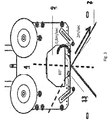
- Fig. 3 shows schematically a state during usage.
- robot arm 1 After turning the object 2, robot arm 1 causes continuing with linear line speed, wherein said linear line speed preferably increases up to 0,2m/s or 0,6m/s or 0,8m/s or 1 m/s or 1,2 m/s or 1, 5m/s or 1,8m/s or 3m/s, in particular to prevent burr resulting from heat increase and in particular during application of cover material 13 onto the object 2.
- cover material 13 in particular foil
- balancing element 5 and/or 11 will move down for releasing the tension.
- Tensioning element/s 6 and/or 10 compensate that movement in such a manner that the predefined or desired tension level remains.
- the end position of cover material 13 application is a releasing point from carrier to applied object 2 respectively plastic part.
- Tensioning element 6 and/or 10 increase/s its level to keep releasing point on a level to prevent burr remaining from the foil carrier.
- part dimension is not a design parameter anymore. It can apply without restriction to many different parts by just changing the fixing jig for objects 2 respectively plastic part.
- the present invention refers to an application head 4 for the application of a covering material 13 onto an object 2.
- This application head 4 preferably comprises at least a base unit 14 and a movable unit 15, wherein movable unit 14 is movable with respect to base unit 15, a roller element 8 for applicating said covering material 13 onto the object 2, wherein the roller element 8 is movable by an actuator means 12, at least one tensioning element 6 for tensioning the covering material 13, wherein the tensioning element 6 is attached to the movable unit 15 and deflectable with respect to the movable unit 14, at least one balancing element 5 for pressure adjustment between the roller element 8 and the object 2, wherein said balancing element 5 is coupled with the movable unit 15 and the base unit 14.
- the present invention can be described as a decorative foil hot stamping systems, which consists of a robotic arm 1, a hot stamping head 4 and a hot silicon roller 8.
- Device preferably can stamp six axes so that stamping process called 3D.
- Main advantages of system are keeping stamping head fixed and moving 3D plastic substrate (in exemplary case, TV frame) with robotic arm. Thus, this system solves critical problems such as stamping heat and tension of tape foil.
Landscapes
- Engineering & Computer Science (AREA)
- Manufacturing & Machinery (AREA)
- Application Of Or Painting With Fluid Materials (AREA)
- Non-Metallic Protective Coatings For Printed Circuits (AREA)
Abstract
Description
- The present invention refers according to
claim 1 to an application head for the application of a covering material onto an object, according toclaim 10 to an application unit for applying covering material to objects and according toclaim 12 to a method for applicating, in particular stamping, of cover material to an object, - Document
US5088406A discloses an automatic stamping machine, comprising an electronic control system to control a driving mechanism to carry an automatic ribbon take-up mechanism and a noise deadening device to perform automatic stamping operation with operational noise simultaneously deadened. This document does not disclose any tension, frequency or pressure control means or steps. - Document
DE102013102984B4 discloses a film-embossing apparatus with a hot-embossing device, which has a heated embossing stamp. With the formation of a contact pressure a transfer layer, arranged on a carrier film, of a hot-embossing film is transferred to a surface of a workpiece. The hot-embossing device has control inputs and outputs. The film-embossing apparatus has an industrial robot with control inputs and outputs. The control inputs and outputs of the hot-embossing device and of the industrial robot are connected to a control unit. The industrial robot is formed such that it guides the workpiece to the hot-embossing device, positions the workpiece on the embossing stamp, guides the workpiece past the embossing stamp, and guides the embossed workpiece away from the hot-embossing device. It can also be provided that the industrial robot positions the hot-embossing device on the workpiece.DE102013102984B4 is problematic since foil tension tends to go down and making coating respectively covering material to trace as well. - Thus, hot stamping is a process, according to which a heat transferable foil with cosmetic appearance is applied with a hot roller silicon cylinder on plastic injected parts (ABS, PC, ABC). It's a very sensitive process. Process parameters are speed of movement and foil feeding balance, hot roller silicone heat, pressure of hot silicon. Foil feeding and releasing balance must be regulated, heat of silicon head must be regulated, turn of cylinder must be controlled and speed of processing must be controlled near zero tolerances. Most of the applications are linear and applied plastic parts are stand without movement. Head is moved along a part in a linear manner. Linear means roller cylinder head moves and transfer cosmetic foil onto a plastic substrate with straight line. Because of this application method it's just applicable on flat plastic parts. It cannot be applied at rounded edges. That makes this process stick to one application. It is possible e.g. to use three linear heads on three sides to perform said application process. This cost three times than one head.
- Also, the interconnection of foil stamping causes connection lines unwanted for end user. Other disadvantages of those systems are they are specially designed for part dimensions. If the applied part is big the system is also big. If head moves heat control and foil balance control are affected because movement of air blow on heated cylinder and foil. So, this type of applications is unsuitable and uncontrollable enough to achieve an acceptable yield. On the other hand, linear hot stamping systems are designed with respect part sides. If three sides are applied with foil, system needs three separated heads one moving on each side of plastic substrate. At the edges, hot roller cylinders meet in a section. At this section intersection of three head there are visually coating trace. This coating trace is unacceptable for end user. There are also similar applications with manipulator system. They have already problems with vertical positioning of application heat. Which is also with gravitational force foil tension tends to go down and making coating trace as well. So, this system also is not suitable for high precision applications with an acceptable yield rate.
- Thus, it is the object of the present invention to provide an application head, an application unit and a method for applying, in particular stamping, covering material onto an object.
- The before mentioned object is solved by an application head for the application of a covering material, in particular hot stamping, onto an object according to
claim 1. The inventive application head comprises preferably at least a base unit and a movable unit, wherein the movable unit is movable with respect to the base unit, a roller element for applicating said covering material onto the object, wherein the roller element is preferably movable by an actuator means, wherein the actuator means preferably connects a roller element head holding the roller element and the base unit, at least one tensioning element for tensioning the covering material, wherein the tensioning element is preferably attached to the movable unit and deflectable with respect to the movable unit, and at least one balancing element for pressure adjustment between application head, in particular moveable element and/or tensioning element and/or the roller element, and the object, wherein said balancing element is coupled with the movable unit and the base unit. - This solution is beneficial since due to the tensioning element and the balancing element the cover material, in particular a continuous material, in particular a longitudinal foil, is subjected with a predefined tension. The covering material preferably comprises or consist of polymer and/or elastomer material. Thus, the tension is preferably above a first threshold and below a second threshold, wherein the first threshold preferably defines a minimum tension, wherein below the first threshold an application of cover material fails with a higher probability due to undefined cover material orientation in during feeding. The second threshold preferably defines maximum tension, wherein above the second threshold damaging, in particular breaking, of the cover material is highly probable. Thus, a tension level between the first threshold and the second threshold is highly beneficial. This solution further enables a very low cost production and enables a high flexibility, thus it can apply many parts without design changes in the system for next applications or designs.
- Further preferred embodiments are subject matter of the following specification parts and/or the dependent claims.
- A second tensioning element is attached to the movable unit according to a further preferred embodiment of the present invention. The first tensioning element is arranged in supply direction of the covering material on a first side of roller element and the second tensioning element is arranged in supply direction of the covering material on a second side of roller element. This embodiment is beneficial since the cover material is guided from one tensioning element to the other tensioning element and thereby passing the roller element. Thus, the cover material is tensioned by the first and second tensioning elements in such a manner that a desired tension is set up where the roller element contacts the cover material or where the roller element can be brought in contact with the cover element. The roller element is preferably movable, in particular in longitudinal direction, between a none contacting state and a contacting state, wherein the roller element contacts the cover material in the contacting state and does not contact the cover material in the none contacting state.
- A second balancing element is attached to the base unit and coupled with the movable unit according to a further preferred embodiment of the present invention. The first balancing element is hereby preferably arranged in supply direction of the covering material on the first side of roller element and the second balancing element is preferably arranged in supply direction of the covering material on the second side of roller element. Thus, first roller element is preferably arranged above first tensioning element and second roller element is preferably arranged above second tensioning element. This embodiment is beneficial since moving the movable unit can be caused or limited by said balancing elements, thus in case an object is brought into contact with the cover material pressure between the cover material and application head unit can be adjusted. Movable unit preferably moves upwards, in particular into a direction that causes less pressure or less pressure increase.
- Each balancing element is according to a further preferred embodiment of the present invention spring loaded by a pneumatic element and/or each tensioning element is spring loaded by a mechanical spring. It is alternatively possible that each balancing element is spring loaded by a mechanical spring and/or each tensioning element is spring loaded by a pneumatic element. It is further possible that all tensioning and balancing elements are spring loaded by pneumatic, hydraulic or mechanical springs. The spring load is preferably adjustable, in particular in dependency of pressure values measured by a pressure sensor arranged at application head and/or arranged at robot arm and/or in dependency of movement data of said robot arm.
- Thus, a novel control of foil tension and feeding with tension and balance rods is provided. This helps to provide a moving system with preferably homogenous pressure /tension level. When system starts applied plastic part and foil are pressed on each other with preferably at least 5KN/sqm or at least 10 KN/sqm or at least or exactly 15 KN/sqm or up to 50 KN/sqm. So, the tension level changes. If balance and tension rods are not controlled foil break off and vice versa foil makes coat trace. Pressure level among flat surface and side are not same. At the edges robot arm pushes with less pressure but this pressure preferably put more tension on foil. Tension rods decrease pressure level; they move upward to achieve application tension level. This also works backwards if the robot pressure decreases. Furthermore, due to robot arm usage novel processing angles and movements for 3D object application are possible.
- At least one pressure sensor unit or element is provided according to a further preferred embodiment of the present invention for detecting pressure applied to roller element and/or to movable unit and/or a sensor unit for detecting temperature, in particular of roller element or covering material, and/or supply speed of covering material or rotating speed of roller element and/or presence of covering material is provided, wherein the sensor unit is arranged on or beside the roller element. This embodiment is beneficial since operation parameters can be adjusted due to detected values and thus breaking of cover material or damaging of the object can be avoided respectively reduced. Beside preferably means spaced apart from the roller element but arranged in such a manner that the sensed parameters are detectable in the area of roller element, in particular in a radius of less than 20cm or of less than 10cm or of less than 5cm around the roller element.
- According to a further preferred embodiment of the present invention a heating unit is provided for heating the roller element and/or for heating the covering material, wherein the heating unit is arranged on movable unit or on roller element head. The roller element and/or the covering material is preferably heated to a temperature above 20°C, in particular above 50°C or above 100°C. The average operation temperature of roller element is hereby preferably below 1000°C, in particular below 500°C. The heating unit preferably comprises an IR light source, wherein the IR light source is highly preferably frequency controlled. This solution is beneficial since heating can be carried out very precise and fast.
- The frequency controlled IR heater/s enable an easy process control and energy savings. With this control system heater operated when its needed with respect effects to heat on surface. These effects are preferably robot movement speed, pressure level and tension parameters. This helps system to save energy.
- Each tensioning element comprises according to a further preferred embodiment of the present invention a contact element for contacting said covering material, wherein said contact elements are arranged (in particular in a no-usage state) in a plane which is aligned with respect to a horizontal plane in an angle of less than 45° or less than 30°or less than 15°, in particular 0°. This embodiment is beneficial since application head is preferably arranged horizontal respectively in a horizontal manner.
- Usage of a stable horizontal located hot stamping head is beneficial since it reduces interference with air, gravity or tension on foil in particular by usage of a synchronized 3D movable six axes robotic process. Due to the robot are the object is moved with high process efficiency. Otherwise, if head moves air circulation due to movement affects temperature level of hot roller silicon this is a process parameter. Also, air circulation due to movement effect thin foil tension. Robot moves under the application head so it preferably never interfaces with foil and preferably never effects any air movement or similar effect. Additional to this robot arm movement and heat transfer from IR heater to roller element, in particular made of silicon, must be regulated. If robot moves faster than IR heater must transfer more heat to silicon vice versa if robot moves low speed as its on edge turns IR heater must transfer less heat. Air circulation effect for foil will be preferably eliminated by programmed path of robot in a reverse turn.
- According to a further preferred embodiment of the present invention coupling means are provided, wherein said base unit can be coupled by means of said coupling means in a stationary manner to a holding element. Said coupling means are preferably suitable to mount the application head to a wall or a holding unit. Stationary manner preferably means an arrangement respectively positioning in a defined position with respect to underground and/or earth and/or walls of facility.
- The roller element is according to a further preferred embodiment of the present invention preferably coupled with an actuator means. Said actuator means preferably comprises a motor for moving the roller element between a first position and a second position, in particular in longitudinal direction. Multiple further positions between the first and second position can be set up. Said motor is preferably a servo controlled motor.
- The before mentioned object is also solved by an application unit for applying, in particular hot stamping, covering material to objects. Said application unit preferably comprises at least an application head, in particular an application head according to
claims 1 to 9, for the application of a covering material onto an object, wherein the application head is arranged in a defined and fix position in space and a robot arm, in particular having six degrees of freedom, wherein objects are moveable by said robot arm to the application head for the application of said covering material. This unit preferably further comprises a feeding means for providing the covering material. This solution is beneficial since damages of the object and/or covering material can be reduced, in particular avoided. Furthermore, such a unit is very precise, fast and flexible. - A control unit is provided according to a further preferred embodiment of the present invention. The operation of the robot arm and application head is hereby preferably synchronized by said control unit, wherein at least the heating unit and/or feeding unit and/or roller element is operated in dependency of robot arm movements. Tension parameters of covering material are preferably maintained during application, in particular by control means, preferably in a predefined range due to control of tensioning elements and/or balancing elements. This range is preferably set up in such a manner that the cover material does not get damaged.
- The before mentioned object is also solved by a method for applicating, in particular stamping, of cover material onto an object. This method preferably comprises at least the steps: Providing a longitudinal continuous covering material, in particular a foil, providing an application head, wherein the covering material is transferred through said application head in a horizontal direction or in an angle of less than 30°, in particular less than 15° or less than 5°, with respect to a horizontal plane and/or wherein said application head is preferably arranged stationary, providing a robot arm for moving objects to be covered with the covering material, applying covering material to an object, wherein said object is moved along a roller element of the application head, wherein said roller element is heated by a heating unit of the application head and wherein the roller element presses the covering material onto the object. This method is beneficial since production can be carried out fast and reliable.
- Object and roller element are according to a further preferred embodiment of the present invention pressed against each other with a pressure between 5KN/m2 and 50KN/m2, in particular with a pressure between 10KN/m2 and 40KN/m2, in particular with a pressure between15KN/m2 and 30KN/m2, and/or heating unit comprises an IR heating element, wherein the IR heating element is operated frequency controlled and/or robot arm moves the object at least during application of covering material with a speed between 0,2m/s and 2m/s, in particular with a speed between 0,5m/s and 1,5m/s, in particular with a speed between 0,7m/s and 1m/s, in particular with a speed of 1 m/s. Preferably are at least two of these parameters controlled by the control unit, wherein the control unit preferably receives sensor values of sensor units for analyzing one or at least one, two or at least two or all of these parameters.
- The application head is according to a further preferred embodiment an application head according to any of
claims 1 to 9, wherein at least one tensioning element and at least one balancing element are causing effects with respect to tension of the covering material during application of the covering material onto the object at the same time, in particular causing a predefined tension profile. The objects are highly preferably TV frames or display frames or automotive parts or mobile devices or white goods or house hold items. - Further benefits, goals and features of the present invention will be described by the following specification of the attached figures, in which exemplarily components of the invention are illustrated. Components of the devices, systems and methods according to the inventions, which match at least essentially with respect to their function can be marked with the same reference sign, wherein such components do not have to be marked or described multiple times with respect to said figures.
- In the following the invention is just exemplarily described with respect to the attached figures.
-
-
Fig. 1 shows a schematic illustration of an application unit according to the present invention; -
Fig. 2 shows a schematic illustration of an application head according to the present invention; and -
Fig. 3 shows a further schematic illustration of the application head. -
Fig. 1 shows an illustration of an application unit according to the present invention, wherein said application unit comprises arobot arm 1, in particular a multi-axis robot, in particular a 6-axis robot arm, and anapplication head 4. Thus, the present invention has one special designedapplication head 4, in particular hot stamping application head assembly, and one externalrobotic arm 1, which works synchronized.Application head 4 androbot arm 1 are preferably physically spaced apart from each other.Robot arm 1 preferably holds and moves ajig 3, whereinjig 3 enables carrying ofobjects 2, in particular screen frames like TV frames, in particularly made of plastic. -
Fig. 2 shows an examples of anapplication head 4. Due to an innovative design, there is preferably a special servo controlled movement. An actuator means 12 preferably comprises a servo controlled silicon cylinder turning motor, which is preferably frequency controlled. Said actuator means 12 preferably causes timing in betweenhead 4,cover material 13 respectively cosmetic foil androbot 1. - Due to the special designed horizontal
head cover material 13, in particular hot stamping foil, is released with preferably twobalancing elements 5, in particular balance rods, and preferably twotensioning elements thin cover material 13, in particular foil, must be tightened enough for hot cylinder press, releasing of at least or exactly one carrier layer, for separating tape-carrier, and for fixing the tape to anobject 13, in particular TV frame. Thecover material 13 is preferably thinner than 0,5mm or 0,1 mm or 0,05mm or 0,01 mm. A heating unit 7 for heating the hot cylinder silicone is preferably frequency controlled and covered for any air blowing interference.Roller element 8, in particular hot roller silicone, is preferably moved on a reverse turn to part movement during stand by. This movement helps frequency controlled heating unit 7, in particular IR heater, to distribute heat onroller element 8, preferably continuously, to keep it at the same temperature level. During application, hot silicon roller respectivelyroller element 8 stops and turns with stamped plastic part. Pressure of the hot silicon roller must be at least 5N/ sqm or at least 25N/sqm or 50 N/square meter or 100N/sqm or up to 5N/ sqm or at least 25N/sqm or 50 N/square meter or 100N/sqm or up to 200N/ sqm or at least 500N/sqm or 1000 N/square meter or 10000N/sqm or 100000N/sqm.Roller element 8 is preferably held byroller element head 9.Roller element head 9 can comprise a motor for turningroller element 8.Roller element head 9 is preferably coupled with actuator means 12. Actuator means 12 causes a movement ofroller element head 9, in particular in longitudinal direction respectively up and down. Actuator means 12 is preferably operated in dependency of pressure applied to application head and/or operation parameters ofrobot arm 1. - Balancing
elements cover material 13, in particular foil.Tensioning elements cover material 13 respectively foil andobject 2 respectively plastic part. - While
object 2 is moving tension ofcover material 13 respectively foil is controlled. Tensioning elements are comprising springs, in particular mechanical springs, respectively are assembled with preferably at least one spring to move down and up. All this controlled tension and balance regulating process helps to rewind a carrier layer, in particular a foil carrier, as well. - This method helps the system to be used in 3D movement which is required for 3D applications like TV frame sides.
Application head 4 is highly preferably not moving. This design solves problems appearing during heating ofroller element 8 and resulting from air turbulence whilehead 4 is moving (state of the art). Also, covermaterial 13, in particular foil, balance can be controlled better with this way. Applied plastic part respectively object 2 preferably touches thecover material 13 in an angle between 20° and 80°, in particular in an angle between 40° and 70° or in an angle between 55° and 65°, in particular in an angle of 60°, on its edge. Movement ofobject 2 respectively part is preferably caused at at least 0,2 m/s or 4m/s or 0,6m/s or 0, 8 m/s or 1 m/s or 1,5m/s or up to 2m/s or 3m/s or 4m/s until the edge is finished. -
Fig. 3 shows schematically a state during usage. - After turning the
object 2,robot arm 1 causes continuing with linear line speed, wherein said linear line speed preferably increases up to 0,2m/s or 0,6m/s or 0,8m/s or 1 m/s or 1,2 m/s or 1, 5m/s or 1,8m/s or 3m/s, in particular to prevent burr resulting from heat increase and in particular during application ofcover material 13 onto theobject 2. During first touch of theobject 2 withcover material 13, in particular foil, balancingelement 5 and/or 11, will move down for releasing the tension. Tensioning element/s 6 and/or 10 compensate that movement in such a manner that the predefined or desired tension level remains. - The end position of
cover material 13 application is a releasing point from carrier to appliedobject 2 respectively plastic part. Tensioningelement 6 and/or 10 increase/s its level to keep releasing point on a level to prevent burr remaining from the foil carrier. - Thus, by using the inventive robotic hot stamping method part dimension is not a design parameter anymore. It can apply without restriction to many different parts by just changing the fixing jig for
objects 2 respectively plastic part. - Therefore, the present invention refers to an
application head 4 for the application of a coveringmaterial 13 onto anobject 2. Thisapplication head 4 preferably comprises at least abase unit 14 and amovable unit 15, whereinmovable unit 14 is movable with respect tobase unit 15, aroller element 8 for applicating said coveringmaterial 13 onto theobject 2, wherein theroller element 8 is movable by an actuator means 12, at least onetensioning element 6 for tensioning the coveringmaterial 13, wherein thetensioning element 6 is attached to themovable unit 15 and deflectable with respect to themovable unit 14, at least onebalancing element 5 for pressure adjustment between theroller element 8 and theobject 2, wherein said balancingelement 5 is coupled with themovable unit 15 and thebase unit 14. In other words, the present invention can be described as a decorative foil hot stamping systems, which consists of arobotic arm 1, ahot stamping head 4 and ahot silicon roller 8. Device preferably can stamp six axes so that stamping process called 3D. Main advantages of system are keeping stamping head fixed and moving 3D plastic substrate (in exemplary case, TV frame) with robotic arm. Thus, this system solves critical problems such as stamping heat and tension of tape foil. -
- 1
- Robot arm
- 2
- object
- 3
- jig
- 4
- application head
- 5
- balancing element
- 6
- tensioning element
- 7
- Heating unit
- 8
- roller element / hot-roller silicon
- 9
- roller element head / hot-roller head
- 10
- second tensioning element
- 11
- second balancing element
- 12
- actuator
- 13
- cover material / decorative foil
- 14
- base unit
- 15
- movable unit
Claims (15)
- Application head (4) for the application of a covering material (13) onto an object (2),
at least comprising
a base unit (14) and a movable unit (15), wherein movable unit (14) is movable with respect to base unit (15),
a roller element (8) for applicating said covering material (13) onto the object (2),
wherein the roller element (8) is movable by an actuator means (12),
at least one tensioning element (6) for tensioning the covering material (13),
wherein the tensioning element (6) is attached to the movable unit (15) and deflectable with respect to the movable unit (14),
at least one balancing element (5) for pressure adjustment between application head and the object (2),
wherein said balancing element (5) is coupled with the movable unit (15) and the base unit (14). - Application head according to claim 1,
characterized in that
a second tensioning element (6) is attached to the movable unit (15),
wherein the first tensioning element (6) is arranged in supply direction of the covering material (13) on a first side of roller element (8) and
wherein the second tensioning element (10) is arranged in supply direction of the covering material (13) on a second side of roller element (8). - Application head according to claim 1 or 2,
characterized in that
a second balancing element (11) is attached to the base unit (14) and coupled with the movable unit (15),
wherein the first balancing element (5) is arranged in supply direction of the covering material (13) on the first side of roller element (8) and
wherein the second balancing element (5) is arranged in supply direction of the covering material (13) on the second side of roller element (8). - Application head according to any of the proceeding claims,
characterized in that
each balancing element (5, 11) is spring loaded by a pneumatic element and/or
each tensioning element (6, 10) is spring loaded by a mechanical spring. - Application head according to any of the proceeding claims,
characterized in that
at least one pressure sensor unit is provided for detecting pressure applied to roller element (8) and/or to movable unit (15) and/or for detecting temperature, in particular of roller element (8) or covering material (13), and/or for detecting supply speed of covering material (13) or rotating speed of roller element (8) and/or presence of covering material (13) is provided,
wherein the sensor unit is arranged on or beside the roller element (8). - Application head according to any of the proceeding claims,
characterized in that
a heating unit (7) is provided for heating the roller element (8) and/or for heating the covering material (13),
wherein the heating unit (7) is arranged on movable unit (15) or on roller element head (9)
and
wherein heating unit (7) comprises an IR light source, wherein the IR light source is frequency controlled. - Application head according to any of the proceeding claims,
characterized in that
each tensioning element (6, 10) comprises a contact element for contacting said covering material (13),
wherein said contact elements are arranged in a plane which is aligned with respect to a horizontal plane in an angle of less than 45° or less than 30°or less than 15°, in particular 0°. - Application head according to any of the proceeding claims,
characterized in that
coupling means are provided,
wherein said base unit (14) can be coupled by means of said coupling means in a stationary manner to a holding element. - Application head according to any of the proceeding claims,
characterized in that
roller element (8) is coupled with the actuator means (12),
wherein said actuator means (12) comprises a motor for moving the roller element in longitudinal direction,
wherein said motor is a frequency controlled servo motor. - Application unit for applying covering material to objects,
at least comprising
an application head (4), in particular an application head (4) according to claims 1 to 9, for the application of a covering material (13) onto an object (2), wherein the application head (4) is arranged in a defined and fix position in space
and
a robot arm (1), in particular having six degrees of freedom,
wherein objects (2) are moveable by said robot arm (1) to the application head (4) for the application of said covering material (13). - Application unit according to claim 10,
characterized in that
a control unit is provided,
wherein operation of the robot arm (1) and application head (4) is synchronized by said control unit,
wherein at least the heating unit (7) is operated in dependency of robot arm movements and wherein tension parameters of covering material (13) during application are maintained, in particular by control means, in a predefined range due to control of tensioning elements (6, 10) and/or balancing elements (5, 11). - Method for applicating, in particular stamping, of cover material to an object, at least comprising the steps:Providing a longitudinal continuous covering material (13), in particular a foil,Providing an application head (4), wherein the covering material (13) is transferred through said application head (4) in a horizontal direction or in an angle of less than 30°, in particular less than 15° or less than 5°, with respect to a horizontal plane and/or wherein said application head (4) is arranged stationaryProviding a robot arm (1) for moving objects (2) to be covered with the covering material (13),Applying covering material (13) to an object (2), wherein said object (2) is moved along a roller element (8) of the application head 4), wherein said roller element (8) is heated by a heating unit (7) of the application head (4) and wherein the roller elements (8) presses the covering material (13) onto the object (2).
- Method according to claim 12,
characterized in that
object (2) and roller element (8) are pressed against each other with a pressure between 5KN/m2 and 50KN/m2, in particular with a pressure between 10KN/m2 and 40KN/m2, in particular with a pressure between15KN/m2 and 30KN/m2,
and/or
heating unit (7) comprises an IR heating element,
wherein the IR heating element is operated frequency controlled
and/or
robot arm (1) moves the object (2) during application of covering material with a speed between 0,2m/s and 2m/s, in particular with a speed between 0,5m/s and 1,5m/s, in particular with a speed between 0,7m/s and 1m/s, in particular with a speed of 1 m/s. - Method according to claims 12 or 13,
characterized in that
application head (4) is an application head (4) according to any of claims 1 to 9,
wherein at least one tensioning element (6, 10) and at least one balancing element (5, 11) are causing effects with respect to tension of the covering material (13) during application of the covering material (13) onto the object (2) at the same time, in particular causing a predefined tension profile. - Method according to claims 12 to 14,
characterized in that
the objects (2) are TV frames or automotive parts or mobile devices or white goods or house hold items.
Priority Applications (2)
| Application Number | Priority Date | Filing Date | Title |
|---|---|---|---|
| EP17157240.7A EP3363618B1 (en) | 2017-02-21 | 2017-02-21 | Stationary hot-stamping head, stamping unit with stationary hot-stamping head and method for applying a cover material onto an object |
| TR2017/03040A TR201703040A2 (en) | 2017-02-21 | 2017-02-28 | Stationary hot-stamping head, stamping unit with stationary hotstamping head and method for applying a cover material onto an object. |
Applications Claiming Priority (1)
| Application Number | Priority Date | Filing Date | Title |
|---|---|---|---|
| EP17157240.7A EP3363618B1 (en) | 2017-02-21 | 2017-02-21 | Stationary hot-stamping head, stamping unit with stationary hot-stamping head and method for applying a cover material onto an object |
Publications (2)
| Publication Number | Publication Date |
|---|---|
| EP3363618A1 true EP3363618A1 (en) | 2018-08-22 |
| EP3363618B1 EP3363618B1 (en) | 2019-12-18 |
Family
ID=58158849
Family Applications (1)
| Application Number | Title | Priority Date | Filing Date |
|---|---|---|---|
| EP17157240.7A Active EP3363618B1 (en) | 2017-02-21 | 2017-02-21 | Stationary hot-stamping head, stamping unit with stationary hot-stamping head and method for applying a cover material onto an object |
Country Status (2)
| Country | Link |
|---|---|
| EP (1) | EP3363618B1 (en) |
| TR (1) | TR201703040A2 (en) |
Cited By (1)
| Publication number | Priority date | Publication date | Assignee | Title |
|---|---|---|---|---|
| CN109177474A (en) * | 2018-09-28 | 2019-01-11 | 上海烟草集团有限责任公司 | A kind of gold stamping device |
Citations (5)
| Publication number | Priority date | Publication date | Assignee | Title |
|---|---|---|---|---|
| US5088406A (en) | 1991-01-29 | 1992-02-18 | Clin Cliang P | Structure of automatic stamping machine |
| DE29503778U1 (en) * | 1994-03-16 | 1995-05-04 | SEKURIT SAINT-GOBAIN Deutschland GmbH & Co. KG, 52066 Aachen | Device for laminating a protective film on a glass pane |
| US20070272347A1 (en) * | 2006-05-25 | 2007-11-29 | Coleman Donald T | Method and apparatus for forming a coating on an element |
| US20140069575A1 (en) * | 2012-09-07 | 2014-03-13 | Ged Integrated Solutions, Inc. | Apparatus and method for guiding film |
| DE102013102984B4 (en) | 2013-03-22 | 2015-01-22 | Leonhard Kurz Stiftung & Co. Kg | Foil stamping device |
-
2017
- 2017-02-21 EP EP17157240.7A patent/EP3363618B1/en active Active
- 2017-02-28 TR TR2017/03040A patent/TR201703040A2/en unknown
Patent Citations (6)
| Publication number | Priority date | Publication date | Assignee | Title |
|---|---|---|---|---|
| US5088406A (en) | 1991-01-29 | 1992-02-18 | Clin Cliang P | Structure of automatic stamping machine |
| DE29503778U1 (en) * | 1994-03-16 | 1995-05-04 | SEKURIT SAINT-GOBAIN Deutschland GmbH & Co. KG, 52066 Aachen | Device for laminating a protective film on a glass pane |
| US20070272347A1 (en) * | 2006-05-25 | 2007-11-29 | Coleman Donald T | Method and apparatus for forming a coating on an element |
| US20140069575A1 (en) * | 2012-09-07 | 2014-03-13 | Ged Integrated Solutions, Inc. | Apparatus and method for guiding film |
| DE102013102984B4 (en) | 2013-03-22 | 2015-01-22 | Leonhard Kurz Stiftung & Co. Kg | Foil stamping device |
| EP2976209A2 (en) * | 2013-03-22 | 2016-01-27 | Leonhard Kurz Stiftung & Co. KG | Film-embossing apparatus |
Cited By (2)
| Publication number | Priority date | Publication date | Assignee | Title |
|---|---|---|---|---|
| CN109177474A (en) * | 2018-09-28 | 2019-01-11 | 上海烟草集团有限责任公司 | A kind of gold stamping device |
| CN109177474B (en) * | 2018-09-28 | 2024-02-06 | 上海烟草集团有限责任公司 | A hot stamping equipment |
Also Published As
| Publication number | Publication date |
|---|---|
| EP3363618B1 (en) | 2019-12-18 |
| TR201703040A2 (en) | 2018-09-21 |
Similar Documents
| Publication | Publication Date | Title |
|---|---|---|
| US11724487B2 (en) | Apparatus and method for control or monitoring a printing system | |
| JP7065847B2 (en) | Needles suitable for direct transfer of semiconductor devices | |
| KR102711179B1 (en) | An apparatus for transfer of semiconductor devices | |
| CN105142881B (en) | Film embossing equipment | |
| EP3403324B1 (en) | Methods and systems for electroadhesion-based manipulation in manufacturing | |
| KR101421396B1 (en) | Demolding device | |
| US20160031582A1 (en) | Labeling machine | |
| JP6779066B2 (en) | How to attach the transport belt | |
| KR20190033111A (en) | FPCB protective film peeling device | |
| EP3363618B1 (en) | Stationary hot-stamping head, stamping unit with stationary hot-stamping head and method for applying a cover material onto an object | |
| US11282730B2 (en) | Bridge apparatus for semiconductor die transfer | |
| US20140107834A1 (en) | Process and apparatus for aligning objects | |
| CN109732604A (en) | A method of the mobile contraposition of manipulator is carried out by electric eye | |
| KR102884671B1 (en) | Sewing automation system with pattern recognition | |
| ITMO20110018A1 (en) | DEVICE FOR HOT PRINTING, PARTICULARLY FOR REFRACTORY AND / OR RIGID MATERIALS. | |
| JP2017001724A (en) | Labeling device | |
| US20050224166A1 (en) | Liner driven component transfer systems and methods | |
| US10951092B2 (en) | Transport system, carriage, positioning apparatus, processing system, and positioning method | |
| US10549522B2 (en) | Processing machine having a plurality of processing stations for the processing of articles | |
| KR101729865B1 (en) | Detaching method and detaching apparatus | |
| KR100768469B1 (en) | Double sided tape attachment device for attaching flexible circuit board to main circuit board | |
| KR101502784B1 (en) | An Apparatus for Attaching Label | |
| KR20190059571A (en) | Apparatus for cutting substrate | |
| US12151470B2 (en) | Apparatus and method for control or monitoring a printing system | |
| KR102438487B1 (en) | surface pressurization device |
Legal Events
| Date | Code | Title | Description |
|---|---|---|---|
| PUAI | Public reference made under article 153(3) epc to a published international application that has entered the european phase |
Free format text: ORIGINAL CODE: 0009012 |
|
| STAA | Information on the status of an ep patent application or granted ep patent |
Free format text: STATUS: THE APPLICATION HAS BEEN PUBLISHED |
|
| AK | Designated contracting states |
Kind code of ref document: A1 Designated state(s): AL AT BE BG CH CY CZ DE DK EE ES FI FR GB GR HR HU IE IS IT LI LT LU LV MC MK MT NL NO PL PT RO RS SE SI SK SM TR |
|
| AX | Request for extension of the european patent |
Extension state: BA ME |
|
| STAA | Information on the status of an ep patent application or granted ep patent |
Free format text: STATUS: REQUEST FOR EXAMINATION WAS MADE |
|
| 17P | Request for examination filed |
Effective date: 20190221 |
|
| RBV | Designated contracting states (corrected) |
Designated state(s): AL AT BE BG CH CY CZ DE DK EE ES FI FR GB GR HR HU IE IS IT LI LT LU LV MC MK MT NL NO PL PT RO RS SE SI SK SM TR |
|
| GRAP | Despatch of communication of intention to grant a patent |
Free format text: ORIGINAL CODE: EPIDOSNIGR1 |
|
| STAA | Information on the status of an ep patent application or granted ep patent |
Free format text: STATUS: GRANT OF PATENT IS INTENDED |
|
| INTG | Intention to grant announced |
Effective date: 20190712 |
|
| GRAS | Grant fee paid |
Free format text: ORIGINAL CODE: EPIDOSNIGR3 |
|
| GRAA | (expected) grant |
Free format text: ORIGINAL CODE: 0009210 |
|
| STAA | Information on the status of an ep patent application or granted ep patent |
Free format text: STATUS: THE PATENT HAS BEEN GRANTED |
|
| AK | Designated contracting states |
Kind code of ref document: B1 Designated state(s): AL AT BE BG CH CY CZ DE DK EE ES FI FR GB GR HR HU IE IS IT LI LT LU LV MC MK MT NL NO PL PT RO RS SE SI SK SM TR |
|
| REG | Reference to a national code |
Ref country code: CH Ref legal event code: EP |
|
| REG | Reference to a national code |
Ref country code: IE Ref legal event code: FG4D |
|
| REG | Reference to a national code |
Ref country code: DE Ref legal event code: R096 Ref document number: 602017009717 Country of ref document: DE |
|
| REG | Reference to a national code |
Ref country code: AT Ref legal event code: REF Ref document number: 1214103 Country of ref document: AT Kind code of ref document: T Effective date: 20200115 |
|
| REG | Reference to a national code |
Ref country code: NL Ref legal event code: MP Effective date: 20191218 |
|
| PG25 | Lapsed in a contracting state [announced via postgrant information from national office to epo] |
Ref country code: FI Free format text: LAPSE BECAUSE OF FAILURE TO SUBMIT A TRANSLATION OF THE DESCRIPTION OR TO PAY THE FEE WITHIN THE PRESCRIBED TIME-LIMIT Effective date: 20191218 Ref country code: BG Free format text: LAPSE BECAUSE OF FAILURE TO SUBMIT A TRANSLATION OF THE DESCRIPTION OR TO PAY THE FEE WITHIN THE PRESCRIBED TIME-LIMIT Effective date: 20200318 Ref country code: NO Free format text: LAPSE BECAUSE OF FAILURE TO SUBMIT A TRANSLATION OF THE DESCRIPTION OR TO PAY THE FEE WITHIN THE PRESCRIBED TIME-LIMIT Effective date: 20200318 Ref country code: GR Free format text: LAPSE BECAUSE OF FAILURE TO SUBMIT A TRANSLATION OF THE DESCRIPTION OR TO PAY THE FEE WITHIN THE PRESCRIBED TIME-LIMIT Effective date: 20200319 Ref country code: LT Free format text: LAPSE BECAUSE OF FAILURE TO SUBMIT A TRANSLATION OF THE DESCRIPTION OR TO PAY THE FEE WITHIN THE PRESCRIBED TIME-LIMIT Effective date: 20191218 Ref country code: SE Free format text: LAPSE BECAUSE OF FAILURE TO SUBMIT A TRANSLATION OF THE DESCRIPTION OR TO PAY THE FEE WITHIN THE PRESCRIBED TIME-LIMIT Effective date: 20191218 Ref country code: LV Free format text: LAPSE BECAUSE OF FAILURE TO SUBMIT A TRANSLATION OF THE DESCRIPTION OR TO PAY THE FEE WITHIN THE PRESCRIBED TIME-LIMIT Effective date: 20191218 |
|
| REG | Reference to a national code |
Ref country code: LT Ref legal event code: MG4D |
|
| PG25 | Lapsed in a contracting state [announced via postgrant information from national office to epo] |
Ref country code: RS Free format text: LAPSE BECAUSE OF FAILURE TO SUBMIT A TRANSLATION OF THE DESCRIPTION OR TO PAY THE FEE WITHIN THE PRESCRIBED TIME-LIMIT Effective date: 20191218 Ref country code: HR Free format text: LAPSE BECAUSE OF FAILURE TO SUBMIT A TRANSLATION OF THE DESCRIPTION OR TO PAY THE FEE WITHIN THE PRESCRIBED TIME-LIMIT Effective date: 20191218 |
|
| PG25 | Lapsed in a contracting state [announced via postgrant information from national office to epo] |
Ref country code: AL Free format text: LAPSE BECAUSE OF FAILURE TO SUBMIT A TRANSLATION OF THE DESCRIPTION OR TO PAY THE FEE WITHIN THE PRESCRIBED TIME-LIMIT Effective date: 20191218 |
|
| PG25 | Lapsed in a contracting state [announced via postgrant information from national office to epo] |
Ref country code: EE Free format text: LAPSE BECAUSE OF FAILURE TO SUBMIT A TRANSLATION OF THE DESCRIPTION OR TO PAY THE FEE WITHIN THE PRESCRIBED TIME-LIMIT Effective date: 20191218 Ref country code: CZ Free format text: LAPSE BECAUSE OF FAILURE TO SUBMIT A TRANSLATION OF THE DESCRIPTION OR TO PAY THE FEE WITHIN THE PRESCRIBED TIME-LIMIT Effective date: 20191218 Ref country code: RO Free format text: LAPSE BECAUSE OF FAILURE TO SUBMIT A TRANSLATION OF THE DESCRIPTION OR TO PAY THE FEE WITHIN THE PRESCRIBED TIME-LIMIT Effective date: 20191218 Ref country code: NL Free format text: LAPSE BECAUSE OF FAILURE TO SUBMIT A TRANSLATION OF THE DESCRIPTION OR TO PAY THE FEE WITHIN THE PRESCRIBED TIME-LIMIT Effective date: 20191218 Ref country code: PT Free format text: LAPSE BECAUSE OF FAILURE TO SUBMIT A TRANSLATION OF THE DESCRIPTION OR TO PAY THE FEE WITHIN THE PRESCRIBED TIME-LIMIT Effective date: 20200513 |
|
| PG25 | Lapsed in a contracting state [announced via postgrant information from national office to epo] |
Ref country code: SK Free format text: LAPSE BECAUSE OF FAILURE TO SUBMIT A TRANSLATION OF THE DESCRIPTION OR TO PAY THE FEE WITHIN THE PRESCRIBED TIME-LIMIT Effective date: 20191218 Ref country code: IS Free format text: LAPSE BECAUSE OF FAILURE TO SUBMIT A TRANSLATION OF THE DESCRIPTION OR TO PAY THE FEE WITHIN THE PRESCRIBED TIME-LIMIT Effective date: 20200418 Ref country code: SM Free format text: LAPSE BECAUSE OF FAILURE TO SUBMIT A TRANSLATION OF THE DESCRIPTION OR TO PAY THE FEE WITHIN THE PRESCRIBED TIME-LIMIT Effective date: 20191218 |
|
| REG | Reference to a national code |
Ref country code: DE Ref legal event code: R097 Ref document number: 602017009717 Country of ref document: DE |
|
| REG | Reference to a national code |
Ref country code: CH Ref legal event code: PL |
|
| REG | Reference to a national code |
Ref country code: AT Ref legal event code: MK05 Ref document number: 1214103 Country of ref document: AT Kind code of ref document: T Effective date: 20191218 |
|
| PLBE | No opposition filed within time limit |
Free format text: ORIGINAL CODE: 0009261 |
|
| STAA | Information on the status of an ep patent application or granted ep patent |
Free format text: STATUS: NO OPPOSITION FILED WITHIN TIME LIMIT |
|
| REG | Reference to a national code |
Ref country code: BE Ref legal event code: MM Effective date: 20200229 |
|
| PG25 | Lapsed in a contracting state [announced via postgrant information from national office to epo] |
Ref country code: LU Free format text: LAPSE BECAUSE OF NON-PAYMENT OF DUE FEES Effective date: 20200221 Ref country code: MC Free format text: LAPSE BECAUSE OF FAILURE TO SUBMIT A TRANSLATION OF THE DESCRIPTION OR TO PAY THE FEE WITHIN THE PRESCRIBED TIME-LIMIT Effective date: 20191218 Ref country code: ES Free format text: LAPSE BECAUSE OF FAILURE TO SUBMIT A TRANSLATION OF THE DESCRIPTION OR TO PAY THE FEE WITHIN THE PRESCRIBED TIME-LIMIT Effective date: 20191218 Ref country code: DK Free format text: LAPSE BECAUSE OF FAILURE TO SUBMIT A TRANSLATION OF THE DESCRIPTION OR TO PAY THE FEE WITHIN THE PRESCRIBED TIME-LIMIT Effective date: 20191218 |
|
| 26N | No opposition filed |
Effective date: 20200921 |
|
| PG25 | Lapsed in a contracting state [announced via postgrant information from national office to epo] |
Ref country code: LI Free format text: LAPSE BECAUSE OF NON-PAYMENT OF DUE FEES Effective date: 20200229 Ref country code: SI Free format text: LAPSE BECAUSE OF FAILURE TO SUBMIT A TRANSLATION OF THE DESCRIPTION OR TO PAY THE FEE WITHIN THE PRESCRIBED TIME-LIMIT Effective date: 20191218 Ref country code: CH Free format text: LAPSE BECAUSE OF NON-PAYMENT OF DUE FEES Effective date: 20200229 Ref country code: AT Free format text: LAPSE BECAUSE OF FAILURE TO SUBMIT A TRANSLATION OF THE DESCRIPTION OR TO PAY THE FEE WITHIN THE PRESCRIBED TIME-LIMIT Effective date: 20191218 |
|
| PG25 | Lapsed in a contracting state [announced via postgrant information from national office to epo] |
Ref country code: FR Free format text: LAPSE BECAUSE OF NON-PAYMENT OF DUE FEES Effective date: 20200229 Ref country code: IE Free format text: LAPSE BECAUSE OF NON-PAYMENT OF DUE FEES Effective date: 20200221 Ref country code: IT Free format text: LAPSE BECAUSE OF FAILURE TO SUBMIT A TRANSLATION OF THE DESCRIPTION OR TO PAY THE FEE WITHIN THE PRESCRIBED TIME-LIMIT Effective date: 20191218 |
|
| PG25 | Lapsed in a contracting state [announced via postgrant information from national office to epo] |
Ref country code: BE Free format text: LAPSE BECAUSE OF NON-PAYMENT OF DUE FEES Effective date: 20200229 Ref country code: PL Free format text: LAPSE BECAUSE OF FAILURE TO SUBMIT A TRANSLATION OF THE DESCRIPTION OR TO PAY THE FEE WITHIN THE PRESCRIBED TIME-LIMIT Effective date: 20191218 |
|
| PG25 | Lapsed in a contracting state [announced via postgrant information from national office to epo] |
Ref country code: MT Free format text: LAPSE BECAUSE OF FAILURE TO SUBMIT A TRANSLATION OF THE DESCRIPTION OR TO PAY THE FEE WITHIN THE PRESCRIBED TIME-LIMIT Effective date: 20191218 Ref country code: CY Free format text: LAPSE BECAUSE OF FAILURE TO SUBMIT A TRANSLATION OF THE DESCRIPTION OR TO PAY THE FEE WITHIN THE PRESCRIBED TIME-LIMIT Effective date: 20191218 |
|
| PG25 | Lapsed in a contracting state [announced via postgrant information from national office to epo] |
Ref country code: MK Free format text: LAPSE BECAUSE OF FAILURE TO SUBMIT A TRANSLATION OF THE DESCRIPTION OR TO PAY THE FEE WITHIN THE PRESCRIBED TIME-LIMIT Effective date: 20191218 |
|
| PGFP | Annual fee paid to national office [announced via postgrant information from national office to epo] |
Ref country code: GB Payment date: 20230221 Year of fee payment: 7 Ref country code: DE Payment date: 20230216 Year of fee payment: 7 |
|
| REG | Reference to a national code |
Ref country code: DE Ref legal event code: R119 Ref document number: 602017009717 Country of ref document: DE |
|
| GBPC | Gb: european patent ceased through non-payment of renewal fee |
Effective date: 20240221 |
|
| PG25 | Lapsed in a contracting state [announced via postgrant information from national office to epo] |
Ref country code: DE Free format text: LAPSE BECAUSE OF NON-PAYMENT OF DUE FEES Effective date: 20240903 |
|
| PG25 | Lapsed in a contracting state [announced via postgrant information from national office to epo] |
Ref country code: GB Free format text: LAPSE BECAUSE OF NON-PAYMENT OF DUE FEES Effective date: 20240221 |
|
| PG25 | Lapsed in a contracting state [announced via postgrant information from national office to epo] |
Ref country code: GB Free format text: LAPSE BECAUSE OF NON-PAYMENT OF DUE FEES Effective date: 20240221 Ref country code: DE Free format text: LAPSE BECAUSE OF NON-PAYMENT OF DUE FEES Effective date: 20240903 |
|
| PGFP | Annual fee paid to national office [announced via postgrant information from national office to epo] |
Ref country code: TR Payment date: 20260220 Year of fee payment: 10 |