EP3363108B1 - Axialflussmaschineanordnung - Google Patents
Axialflussmaschineanordnung Download PDFInfo
- Publication number
- EP3363108B1 EP3363108B1 EP16784270.7A EP16784270A EP3363108B1 EP 3363108 B1 EP3363108 B1 EP 3363108B1 EP 16784270 A EP16784270 A EP 16784270A EP 3363108 B1 EP3363108 B1 EP 3363108B1
- Authority
- EP
- European Patent Office
- Prior art keywords
- machine
- stator
- clutch
- rotor
- housing
- Prior art date
- Legal status (The legal status is an assumption and is not a legal conclusion. Google has not performed a legal analysis and makes no representation as to the accuracy of the status listed.)
- Active
Links
Images




Classifications
-
- H—ELECTRICITY
- H02—GENERATION; CONVERSION OR DISTRIBUTION OF ELECTRIC POWER
- H02K—DYNAMO-ELECTRIC MACHINES
- H02K7/00—Arrangements for handling mechanical energy structurally associated with dynamo-electric machines, e.g. structural association with mechanical driving motors or auxiliary dynamo-electric machines
- H02K7/10—Structural association with clutches, brakes, gears, pulleys or mechanical starters
- H02K7/108—Structural association with clutches, brakes, gears, pulleys or mechanical starters with friction clutches
-
- H—ELECTRICITY
- H02—GENERATION; CONVERSION OR DISTRIBUTION OF ELECTRIC POWER
- H02K—DYNAMO-ELECTRIC MACHINES
- H02K1/00—Details of the magnetic circuit
- H02K1/06—Details of the magnetic circuit characterised by the shape, form or construction
- H02K1/12—Stationary parts of the magnetic circuit
- H02K1/18—Means for mounting or fastening magnetic stationary parts on to, or to, the stator structures
- H02K1/182—Means for mounting or fastening magnetic stationary parts on to, or to, the stator structures to stators axially facing the rotor, i.e. with axial or conical air gap
-
- H—ELECTRICITY
- H02—GENERATION; CONVERSION OR DISTRIBUTION OF ELECTRIC POWER
- H02K—DYNAMO-ELECTRIC MACHINES
- H02K1/00—Details of the magnetic circuit
- H02K1/06—Details of the magnetic circuit characterised by the shape, form or construction
- H02K1/12—Stationary parts of the magnetic circuit
- H02K1/20—Stationary parts of the magnetic circuit with channels or ducts for flow of cooling medium
-
- H—ELECTRICITY
- H02—GENERATION; CONVERSION OR DISTRIBUTION OF ELECTRIC POWER
- H02K—DYNAMO-ELECTRIC MACHINES
- H02K1/00—Details of the magnetic circuit
- H02K1/06—Details of the magnetic circuit characterised by the shape, form or construction
- H02K1/22—Rotating parts of the magnetic circuit
- H02K1/27—Rotor cores with permanent magnets
- H02K1/2793—Rotors axially facing stators
- H02K1/2795—Rotors axially facing stators the rotor consisting of two or more circumferentially positioned magnets
- H02K1/2798—Rotors axially facing stators the rotor consisting of two or more circumferentially positioned magnets where both axial sides of the stator face a rotor
-
- H—ELECTRICITY
- H02—GENERATION; CONVERSION OR DISTRIBUTION OF ELECTRIC POWER
- H02K—DYNAMO-ELECTRIC MACHINES
- H02K15/00—Processes or apparatus specially adapted for manufacturing, assembling, maintaining or repairing of dynamo-electric machines
- H02K15/02—Processes or apparatus specially adapted for manufacturing, assembling, maintaining or repairing of dynamo-electric machines of stator or rotor bodies
- H02K15/03—Processes or apparatus specially adapted for manufacturing, assembling, maintaining or repairing of dynamo-electric machines of stator or rotor bodies having permanent magnets
-
- H—ELECTRICITY
- H02—GENERATION; CONVERSION OR DISTRIBUTION OF ELECTRIC POWER
- H02K—DYNAMO-ELECTRIC MACHINES
- H02K15/00—Processes or apparatus specially adapted for manufacturing, assembling, maintaining or repairing of dynamo-electric machines
- H02K15/16—Centring rotors within the stators
-
- H—ELECTRICITY
- H02—GENERATION; CONVERSION OR DISTRIBUTION OF ELECTRIC POWER
- H02K—DYNAMO-ELECTRIC MACHINES
- H02K15/00—Processes or apparatus specially adapted for manufacturing, assembling, maintaining or repairing of dynamo-electric machines
- H02K15/16—Centring rotors within the stators
- H02K15/165—Balancing the rotors
-
- H—ELECTRICITY
- H02—GENERATION; CONVERSION OR DISTRIBUTION OF ELECTRIC POWER
- H02K—DYNAMO-ELECTRIC MACHINES
- H02K16/00—Machines with more than one rotor or stator
- H02K16/02—Machines with one stator and two or more rotors
-
- H—ELECTRICITY
- H02—GENERATION; CONVERSION OR DISTRIBUTION OF ELECTRIC POWER
- H02K—DYNAMO-ELECTRIC MACHINES
- H02K21/00—Synchronous motors having permanent magnets; Synchronous generators having permanent magnets
- H02K21/12—Synchronous motors having permanent magnets; Synchronous generators having permanent magnets with stationary armatures and rotating magnets
- H02K21/24—Synchronous motors having permanent magnets; Synchronous generators having permanent magnets with stationary armatures and rotating magnets with magnets axially facing the armatures, e.g. hub-type cycle dynamos
-
- H—ELECTRICITY
- H02—GENERATION; CONVERSION OR DISTRIBUTION OF ELECTRIC POWER
- H02K—DYNAMO-ELECTRIC MACHINES
- H02K7/00—Arrangements for handling mechanical energy structurally associated with dynamo-electric machines, e.g. structural association with mechanical driving motors or auxiliary dynamo-electric machines
- H02K7/003—Couplings; Details of shafts
-
- H—ELECTRICITY
- H02—GENERATION; CONVERSION OR DISTRIBUTION OF ELECTRIC POWER
- H02K—DYNAMO-ELECTRIC MACHINES
- H02K7/00—Arrangements for handling mechanical energy structurally associated with dynamo-electric machines, e.g. structural association with mechanical driving motors or auxiliary dynamo-electric machines
- H02K7/08—Structural association with bearings
- H02K7/085—Structural association with bearings radially supporting the rotary shaft at only one end of the rotor
-
- H—ELECTRICITY
- H02—GENERATION; CONVERSION OR DISTRIBUTION OF ELECTRIC POWER
- H02K—DYNAMO-ELECTRIC MACHINES
- H02K2205/00—Specific aspects not provided for in the other groups of this subclass relating to casings, enclosures, supports
- H02K2205/09—Machines characterised by drain passages or by venting, breathing or pressure compensating means
-
- H—ELECTRICITY
- H02—GENERATION; CONVERSION OR DISTRIBUTION OF ELECTRIC POWER
- H02K—DYNAMO-ELECTRIC MACHINES
- H02K7/00—Arrangements for handling mechanical energy structurally associated with dynamo-electric machines, e.g. structural association with mechanical driving motors or auxiliary dynamo-electric machines
- H02K7/006—Structural association of a motor or generator with the drive train of a motor vehicle
Definitions
- the present invention relates to an axial flux machine, in particular an axial flux machine comprising a clutch arrangement.
- FIG. 1a shows the general configuration of an axial flux machine of the present invention with a pair of rotors R1, R2 to either side of a stator S - although a simple structure of the present invention could omit one of the rotors.
- an air gap G between a rotor and a stator and in an axial flux machine the direction of flux through the air gap is substantially axial.
- FIG. 1b illustrates the basic configurations of a Torus NS machine, a Torus NN machine (which has a thicker yoke because the NN pole arrangement requires flux to flow through the thickness of the yoke), and a YASA (Yokeless and Segmented Armature) topology.
- the illustration of the YASA topology shows cross-sections through two coils, the cross-hatched area showing the windings around each coil.
- dispensing with the stator yoke provides a substantial saving in weight and iron losses, but one drawback is loss of rigid structure in which a bearing can be mounted to support rotors.
- a bearing is mounted within the stator confines and magnetic forces from rotors on either side of the stator are axially balanced.
- Rotors being designed to resist bending towards the stator.
- the air gap between rotor and stator for axial flux motors is small typically of the order of 1mm. Smaller gaps lead to higher motor torque and power output and is seen as beneficial.
- manufacturing stack-up tolerances derived from stator and rotor components can lead to variable air gap from motor to motor and hence variable output characteristics. In the limit there is possibility of interference of rotor on stator and hence rotor not being able to rotate and a motor being inoperable or catastrophic motor failure if interference occurs during use.
- WO2010/092402 teaches a two stage rotor arranged one at either end of the stator bars, with two air gaps between the ends of the bars and the rotor stages, an annular housing retaining and mounting the stator; a bearing between the rotor and stator.
- the rotor is thus not otherwise supported in or on the housing and air gaps are set by stator width, bearing length and bearing support faces on rotors.
- This arrangement provides excellent repeatability of said air gap in motor production, but the teaching of WO2010/092402 lacks flexibility particularly when interfacing with a clutch which is sometimes a requirement for these motors when they are used in hybrid machines. In hybridising existing machines there is particular commercial value if drive train components can be moved to accommodate an electric machine within the drive chain assembly and to this end an integrated motor clutch is useful.
- Thomas US6585066 has integrated a wet multi-plate clutch within a radial flux motor, but there are significant shortcomings from taking this approach including; a large diameter of motor, risk of electrical shorts in end-windings of the stator due to debris from the clutch, difficulty of rotor to stator assembly and increased axial length due to stator end-windings.
- a radial flux motor is of larger diameter than an axial flux machine if both machines house a concentric clutch, because a radial flux machine has concentric stator and rotor and the rotor hollow cavity must be large enough to house a clutch. This pushes out the stator diameter by at least the thickness of the rotor stage.
- an axial flux machine has rotors which sit parallel to the stator and an equivalent axial flux machine has a diameter less than its radial counterpart by at least the thickness of the radial flux rotor annulus.
- a radial flux machine has exposed stator end windings which protrude beyond the width of the rotor stage. Stator end-windings thereby increase axial length of a motor for no power or torque gain.
- An equivalent axial flux machine of the present invention has stator bars on which are wound coils, there being no end-windings the axial length of the stator is thereby increased only by the rotor axial length which is comparable to the over-hang length of stator end-windings. This is a significant reason for improved power and torque density from axial flux machines.
- stator coils not all axial flux machines have protected stator coils, but the stator of the present invention has enclosed stator coils which are protected from clutch wear debris and thereby are not prone to electrical short circuits.
- the present invention therefore provides an axial flux machine in accordance with the independent claim appended hereto.
- an axial flux machine comprising: a stator comprising a stator housing enclosing a plurality of stator bars disposed circumferentially at intervals around an axis of the machine, each of the stator bars having a set of coils wound therearound for generating a magnetic field, and the stator housing having an annular shape forming a hollow region about the axis of the machine; a rotor comprising a set of permanent magnets and mounted for rotation about the axis of the machine, the rotor being spaced apart from the stator along the axis of the machine to define a gap between the stator and rotor and in which magnetic flux in the machine is generally in an axial direction, and the rotor formed of an annulus and having a hollow central region about the axis of the machine; a clutch mechanism located co-axially with the axis of the machine and located within the hollow regions of the rotor and stator, the clutch mechanism comprising: a clutch basket comprising a first set of one or more
- Such an arrangement provides a machine in a very compact package.
- a suitable clutch mechanism can be housed within the confines of the machine.
- Machines comprising clutch assemblies having a 150mm diameter have been incorporated into an axial flux machine having an outer diameter of 325mm to 335mm and an axial length of no more than 100mm, whilst still being able to provide up to 500Nm of torque. This offers a machine that may easily be integrated into a hybrid power train, or even into a single unit power train with an integrated clutch.
- the machine may also comprise a machine housing enclosing the rotor, the machine housing being mounted to the stator housing.
- the machine may also comprise a radial bearing between the machine housing and the first engagement surface, and a clutch plate bearer bearing between the machine housing and the second engagement surface, the rotor being co-journaled with the first engagement surface.
- the clutch may comprise a clutch piston for driving the sets of clutch plates in and out of engagement with one another. Furthermore, the machine may also comprise a piston spring, for biasing the clutch piston.
- the clutch may be a wet or dry clutch.
- the machine may also comprise a second rotor disposed on an opposite side of the stator to the first rotor, the second rotor comprising a set of permanent magnets on a first side of the second rotor facing the stator, the second rotor being mounted for rotation about the axis of the machine and relative to the stator, the second rotor being spaced apart from the stator along the axis of the machine to define an axial gap between the stator and second rotor and in which magnetic flux in the machine is generally in an axial direction.
- the double-rotor variant described is preferred, since this increased the overall torque output of the machine, as the magnetic field at both ends of the stator bars is utilised for motive force.
- the clutch basket When there are two rotors, the clutch basket extends axially in the hollow regions and the second rotor is mounted on the clutch basket such that the first and second rotors rotate together.
- a second machine housing may also be provided to enclose the second rotor, the second machine housing being mounted to the stator housing. Again, this provides a rigid structure.
- the first engagement surface is an input to the machine, and the second engagement surface is an output of the machine.
- the first engagement surface is an output of the machine, and the second engagement surface is an input to the machine.
- the first and/or second engagement surfaces may comprise splines for engagement with respective shafts.
- the stator housing may defines a chamber incorporating cooling medium in contact with the coils to cool the coils, the stator housing including a port for supply and a port for drainage of the cooling medium. This enables heat to be extracted from the machine.
- the machine is a toque source, a motor or generator.
- a method of assembling an axial flux machine comprising a clutch mechanism, the method comprising: supplying a clutch mechanism, the clutch mechanism comprising a clutch basket comprising a first set of one or more clutch plates and having a first engagement surface for coupling torque in or out of the machine, and a clutch plate bearer comprising a second set of one or more clutch plates and having a second engagement surface for coupling torque in or out of the machine, the clutch basket and clutch plate bearer being mounted for rotation about an axis of the machine; attaching a first rotor to an outer surface of the clutch basket, the first rotor comprising an annulus having a hollow central region and having a set of permanent magnets disposed circumferentially at intervals around the axis of the machine facing inward of the machine; applying a spacer to the surface of first rotor comprising the permanent magnets; arranging a stator co-axially with the clutch and adjacent the first rotor such that the spacer is contacted by a first side of the stator and the
- the step of pulling the stator away from the first rotor comprises: arranging a clutch radial bearing on an outer surface of the first engagement surface of the clutch basket; arranging a machine housing on a side of the stator opposite the side adjacent to the first rotor, the machine housing extending between the stator housing and the clutch radial bearing; providing an axial shim in an axial path between the machine cover and the clutch basket; and attaching the machine housing to the stator housing, wherein the axial shim has a thickness that defines an axial position of the machine housing relative to the clutch basket such that when the machine cover is driven into attachment with the stator housing, the stator moves axially away from the first rotor.
- the axial shim may be provided between the machine housing and an outer race of the clutch radial bearing, or between the clutch basket and an inner race of the clutch radial bearing.
- the step of providing an axial shim may comprise: measuring at least one axial length of a portion within the machine; and selecting an axial shim thickness depending on the at least one measured axial length such that the step of attaching the machine cover to the stator housing causes sufficient axial movement of the stator in order to move the stator axially away from the first rotor.
- the at least one measured axial length of a portion within the machine is one or more of: an axial distance between the clutch radial bearing and the first rotor; and an axial length of the machine housing.
- the clutch basket may comprises a first rotor engagement face for attaching the first rotor thereto, the first rotor engagement face being axially positioned on the clutch basket to define the axial position of the first rotor, and to define the axial airgap between the first rotor and stator.
- the step of pulling the stator away from the first rotor preferably releases the spacer from between the first rotor and stator.
- the method may further comprise: attaching a second rotor to the outer surface of the clutch basket, the second rotor comprising an annulus having a hollow central region and having a set of permanent magnets disposed circumferentially at intervals around the axis of the machine facing inward of the machine, the second rotor being attached at a position of the clutch basket that is adjacent a second side of the stator, the second side of the stator being opposite the first side of the stator, wherein the step of attaching a second rotor occurs prior to the step of pulling the stator away from the first rotor, and wherein the step of pulling the stator away from the first rotor comprises centring the stator between the first and second rotors.
- the machine housing covers the second rotor, which protects the rotor from the external environment.
- the at least one measured axial length of a portion within the machine may also be one or more of: an axial distance between the clutch radial bearing and the second rotor; and an axial length of the machine housing.
- the clutch basket comprises a second rotor engagement face for attaching the second rotor thereto, the second rotor engagement face being axially separated from the first rotor engagement face on the clutch basket to define the axial distance between the first and second rotors, and to define the axial airgaps between the first rotor and stator and the second rotor and stator.
- the rotor may be attached to the clutch basket by push-fit, bolt or screw fixings, or hot shrink fit.
- the spacer may have an axial thickness that is less than a desired air-gap between the first rotor and stator of the assembled machine.
- the method may further comprise: arranging a clutch plate bearing on an outer surface of the second engagement surface of the clutch plate bearer; arranging a machine housing to cover the first rotor, the machine housing extending between the stator housing and the clutch plate bearing; and attaching the machine housing to the stator housing.
- The provides a rigid structure, and covers and encloses the first rotor from the external environment.
- Figure 1c shows a schematic illustration of a yokeless and segmented armature machine 10.
- the machine 10 comprises a stator 12 and two rotors 14a,b.
- the stator 12 is a collection of separate stator bars 16 spaced circumferentially about a rotation axis 20 of the rotors 14a,b.
- Each bar 16 has its own axis (not shown) which is preferably, but not essentially, disposed parallel to the rotation axis 20.
- Each end of each stator bar is provided with a shoe 18a,b which serves a physical purpose of confining a coil stack 22, which stack 22 is preferably of square/rectangular section insulated wire so that a high fill factor can be achieved.
- the coils 22 are connected to an electrical circuit (not shown) that, in the case of a motor, energizes the coils so that the poles of the resultant magnetic fields generated by the current flowing in the coils is opposite in adjacent stator coils 22.
- the two rotors 14a,b carry permanent magnets 24a, b that face one another with the stator coil 22 between (when the stator bars are inclined - not as shown - the magnets are likewise).
- Two air gaps 26a,b are disposed between respective shoe and magnet pairs 18a/24a, 18b/24b.
- the coils 22 are energized so that their polarity alternates serving to cause coils at different times to align with different magnet pairs, resulting in torque being applied between the rotor and the stator.
- the rotors 14a,b are generally connected together (for example by a shaft, not shown) and rotate together about the axis 20 relative to the stator 12.
- the magnetic circuit 30 is provided by two adjacent stator bars 16 and two magnet pairs 24a,b and a back iron 32a,b for each rotor links the flux between the back of each magnet 24a,b facing away from the respective coils 22.
- the stator coils 16 are enclosed within a housing that extends through the air gap 26a, b and which defines a chamber supplied with a cooling medium.
- a stator 12a is shown in which the stator coils are located between plastic material clam shells 42a, b. These clamshells have external cylindrical walls 44, internal cylindrical walls 46, and annular radially disposed walls 48.
- the radial walls 48 include internal pockets 50 to receive the shoes 18a,b of the stator bars 16 and serve to locate the stator coil assemblies 16, 22, 18a,b when the two clam shell housings 42a, b of the stator 12a are assembled together.
- the stator housing 42a, b defines spaces 52 internally of the coils 22 and externally at 54 around the outside of the coils 22 and there are spaces 56 between the coils.
- the spaces 52,54,56 are interlinked defining a cooling chamber.
- the stator housing 42a,b is provided with ports that allow cooling medium such as oil to be pumped into the spaces 52,54,56 to circulate around the coils and cool them.
- the coil cores may be laminated with the inter-lamination insulation parallel to the desired flux direction.
- the coil cores may also be formed from soft-iron particles coated with electrical insulation and moulded to a desired shape (soft magnetic composites - SMC), being bound together by the insulation matrix.
- An example SMC may comprise glass-bonded iron particles, a thin layer (typically ⁇ 10 ⁇ m) of glass bonding and mutually electrically insulating the iron particles, leaving some residual porosity.
- a high-temperature, high-pressure compaction process is used to mould the component into a complex shape, capable of producing three-dimensional magnetic flux patterns with an excellent form factor and enabling a high fill factor winding to be employed, wound straight onto SMC teeth.
- the shoes and stator bar may be formed separately and subsequently assembled; a shoe may have a central region with an axial direction of minimum reluctance and an outer region with a radial direction of minimum reluctance (see WO2012/022974 ).
- Figures 4 to 10 show an axial flux machine 100 according to the present invention. Whilst these figures show an axial flux machine having two rotors either side of a stator, it is envisaged that the present invention is also applicable to axial flux machines having only one rotor disposed on one side of the stator, in which case one of the rotors shown in the figures is not present and a yoke provides the magnetic return path.
- the axial flux machine 100 comprises a stator 102 and a rotor 104, which has two stages 104a, b, disposed either side of the stator 102 and axially spaced apart from the stator to provide axial air gaps.
- a clutch assembly 106 is provided between the stator and rotor.
- the clutch assembly 106 comprises a clutch basket 108 having one or more clutch plates 128 located on an inner surface, and the clutch assembly 106 also comprises a clutch plate bearer 112, which also has one or more clutch plates 132 located on an outer surface.
- the clutch plate bearer 112 sits in, and rotates, co-axially within the clutch basket 108 such that the respective clutch plates sit interdigitated with one another, and may be driven in and out of engagement with one another.
- the clutch basket and clutch plate bearer When the clutch plates are engaged, the clutch basket and clutch plate bearer rotate in unison. When disengaged, the clutch basket and clutch plate bearer may rotate independently.
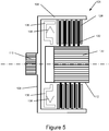
- FIG. 5 shows a simplified driving mechanism for the clutch 106, which comprises a clutch piston 136, which is driven (for example hydraulically or by a cable) to drive the clutch plates 128, 132 into engagement with one another.
- a clutch piston spring 138 is arranged to return the piston 136 to its resting position and thus release the clutch plates 128, 132 from engagement.
- the clutch piston 136 and piston spring 138 could be arranged such that the piston is biased by the spring 138 in a position to drive the clutch plates 128, 132 into engagement with one another, and the clutch piston 136 is driven (for example hydraulically or by a cable) away from the clutch plates 128, 132 such that the clutch plates are released from engagement.
- the chosen orientation will depend on the application for such a machine.
- the clutch basket 108 has an engagement surface 110 and the clutch plate bearer 112 has an engagement surface 130.
- Each of these engagement surfaces 110, 130 enables coupling to the machine via shafts or other means in order to provide torque to the machine or receive torque from the machine.
- the engagement surfaces 110, 130 are shown with splined engagements, although other connection mechanism between a shaft and the respective engagement surface 110, 130 would be apparent to the reader.
- the engagement surface 110 of the clutch basket 108 may be an input or output of the machine.
- the engagement surface 130 of the clutch plate bearer 112 may be an input or output of the machine.
- the first rotor 104a and second rotor 104b are mounted on the clutch basket 108 such that the first and second rotors rotate in unison, and relative to the stator.
- the rotors 104a,b have radial walls mounting a set of permanent magnets 124a,b. Either or both of rotors 104a,b provide a drive input/output, in the case of a generator/motor respectively, but for simplicity this is not shown in the figures.
- the stator 102 has a housing 120 comprising first and second radial walls and generally cylindrical inner and outer walls, defining a chamber within which coolant may circulate.
- the housing encloses a set of stator coils; these and their electrical connections are not shown for simplicity.
- the coils are wound around pole pieces (also not shown for simplicity).
- the machine is provided with first and second machine housings 114a,b, disposed, and mounted to, either side of the stator housing.
- a clutch radial bearing 116 is seated on an outer surface of the clutch basket, with an outer race of the clutch radial bearing 116 supporting the inner radial end of the machine housing 114a.
- a clutch plate bearer bearing 118 is seated on an outer surface of the clutch plate bearer 112, with an outer race of the clutch plate bearer bearing 118 supporting the inner radial end of the machine housing 114b.
- the clutch basket 108 (in unison with the rotors 104a,b) and clutch plate bearer 112 may thus rotate relative to the machine housings 114a,b and stator 102.
- the machine housings 114a,b together with the stator housing, and bearings 116, 118 against the clutch basket 108 and clutch plate bearer 112 form a rigid structure for the machine.
- the machine can be offered in a very compact package.
- a suitable clutch mechanism 106 can be housed within the confines of the machine housing 114a,b.
- Machines comprising clutch assemblies 106 having a 150mm diameter have been incorporated into an axial flux machine having an outer diameter of 325mm to 335mm and an axial length of no more than 100mm, whilst still being able to provide up to 500Nm of torque. This offers a machine that may easily be integrated into a hybrid power train, or even into a single unit power train with an integrated clutch.
- the machine may be a motor, a torque source, or a generator.
- the YASA (Yokeless And Segmented Armature) motor of the present invention preferably has a single annular stator on either side of which there lies a rotor with permanent magnets arranged with north and south poles lying parallel to the rotation axis, interacting with armature pole pieces across air gaps, one for each rotor and stator side.
- This arrangement balances the considerable attractive force of permanent magnet rotors towards the stator and the stator thereby receives a net attraction of close to zero.
- the following method of assembly takes special advantage of the unique topology of a single stator, double rotor axial flux motor enabling a simple and elegant assembly method around a clutch.
- the assembly method may also be applied to a single rotor, single stator topology.
- Multi-plate wet clutches are particularly challenging to fit within a short axial length precisely because of the axial length required of a multi-plate stack and the following description of assembly teaching a solution to this most challenging topology, may also be applied to single plate wet and dry clutches for which assembly within the short axial length of an axial flux motor is considerably easier. Indeed because rotors are axially placed the stator diameter may accommodate a single dry plate clutch without recourse to enlarging the motor diameter, which would necessarily occur for the concentric motor topology of radial machines.
- a hydraulically actuated multi-plate clutch 106 is held in a fixture and a right hand side (first) rotor 104a is fixedly attached to the outer periphery of the clutch basket 108. Attachment may be by push-fit, bolt or screw fixing, or hot shrink fit or any other appropriate attachment method that holds the rotor "as one" with the clutch basket 108.
- spacers 122 are then applied to the magnet i.e. stator facing face of the right-hand rotor 104a.
- spacer 122 may be a single component annular disc with keyhole shaped central aperture to allow removal by radial movement, or it may be multi-component pieces placed to provide even support to the rotor.
- the spacers 122 may be marginally ferromagnetic so as to be held lightly in position when placed on the rotor carrying permanent magnets.
- the total thickness of the spacers is preferably thinner (for example, ⁇ 100 microns) of the desired stator to rotor axial airgap.
- the annular stator 102 having a central aperture larger than the diameter of the clutch basket 108, is jacked into place with clutch basket 106 positioned centrally within the stator aperture, the annular stator 102 is allowed to approach and then contact the spacer 122 protecting the first rotor 104a, the spacer 122 being firmly compressed by the stator 102 to rotor 104a attractive force and fully supporting the stator 102.
- the jacking arrangement may then be removed.
- stator 102 and right-hand (first) rotor 104a With stator 102 and right-hand (first) rotor 104a in place firmly contacting the spacer 122 separating rotor and stator from touching and maintaining a stator to rotor airgap just short of the optimum, the left-hand (second) rotor 104b is jacked towards the stator 102 and is attached fixedly to the clutch basket 108.
- the rotor attachment faces on the clutch basket 108 are of axial separation to accept the stator 102 and provide optimum air gaps between stator 102 and left 104b and right 104a hand rotors.
- stator 102 The assembly methods of stators provides a narrow and known tolerance on stator 102 width such that from motor to motor a small and acceptable variation in physical air gap occurs when a stator 102 is placed between right 104a and left-hand 104b rotors. It remains for the stator 102 to be pulled away from the first rotor 104a and centred between the rotors 104a,b to give an equal air gap between stator 102 and either rotor 104a,b.
- a clutch radial bearing 116 is arranged on the outer surface of the engagement surface of the clutch basket 108. Its axial faces are reference points with respect to the right and left-hand rotor 104a,b axial positions and may thus be used to define a position relative to the clutch basket 108 in order to pull the stator 102 away from the first rotor 104a in order to achieve an optimal or desired gap between the first and second rotors 104a,b during assembly.
- the axial position of the stator 102 is adjusted during assembly using a machine housing 114b, which extends between the clutch radial bearing 116 and the stator housing 120.
- the basic principle is that by using a relatively stiff machine housing 114b and fixing one end of the machine housing 114b to the outer race of the clutch radial bearing 116 (which is at a known position relative to the rotors 104a,b on the clutch basket 106), attaching the machine housing 114b to the stator housing 120 will pull the stator 102 away from the first rotor 104a and into a central axial position between the first and second rotors 104a,b.
- one or more shims 140 may be required to set the correct axial distance between the machine housing 114b and the clutch basket 108.
- a desired position of the machine housing 114b relative to the clutch basket 106 may be calculated, and the desired shim 140 thickness chosen:
- the shim 140a may sit either between the outer race of the clutch radial bearing 116 and the machine housing 114b (in which case the axial position of the machine housing 114b moves relative to the clutch basket 108 and clutch radial bearing 116), or the shim 140b may sit between the inner race of the clutch plate bearing 116 and the clutch basket 108 (in which case the axial position of the clutch radial bearing 116 and machine housing 114b are moved relative to the clutch basket 108).
- stator housing 120 Bolts connecting stator 120 outer housing to left-hand machine housing 114b are tightened and in so doing pull the stator 102 into a central position between right and left-hand rotors 104a,b.
- the spacers 122 providing separation between stator 102 and right-hand rotor 104a now fall loose (since the first rotor and stator are separated) and may be easily removed.
- right-hand machine housing 114a may be applied and bolted to the stator housing 120, with the inner periphery of the machine housing 114a supported by a clutch plate bearer bearing 118 mounted to the second engagement surface of the clutch plate bearer 112.
- the clutch mechanism is provided, the first rotor is attached to the clutch basket, as above. Then the spacer is applied to the first rotor prior to the stator being brought into position about the clutch basket and being brought into contact with the spacer.
- the clutch radial bearing is positioned on the first engagement surface of the clutch basket, and a machine housing is positioned between the clutch radial bearing and the stator housing (but this time extending over the area in which the second rotor would go, but is not present in this method), and the machine housing being brought into contact and attached to the stator housing pulls the stator away axially from the first rotor.
- a shim is chosen to position the machine housing at the desired axial position in order to pull the stator away from the rotor to the desired axial position when the machine housing and stator housing are attached to one another.
- the shim thickness is chosen as described above (although not with reference to the second rotor, since there is no second rotor in this method).
- the machine housing covering the first rotor may also be applied to the machine as described above.
Landscapes
- Engineering & Computer Science (AREA)
- Power Engineering (AREA)
- Manufacturing & Machinery (AREA)
- Connection Of Motors, Electrical Generators, Mechanical Devices, And The Like (AREA)
- Permanent Magnet Type Synchronous Machine (AREA)
- Hydraulic Clutches, Magnetic Clutches, Fluid Clutches, And Fluid Joints (AREA)
Claims (8)
- Axialflussmaschine (100), die Folgendes umfasst:einen Stator (102), der ein Statorgehäuse (120) umfasst, das mehrere Statorstäbe umschließt, die in Umfangsrichtung in Abständen um die Achse der Maschine angeordnet sind, wobei jeder der Statorstäbe einen Satz von Spulen aufweist, die um denselben gewickelt sind, um ein Magnetfeld zu erzeugen, und das Statorgehäuse (120) eine erste und eine zweite radiale Wand und eine innere und eine äußere zylindrische Wand umfasst, um ein ringförmig gestaltetes Gehäuse bereitzustellen, das einen hohlen Bereich um die Achse der Maschine bildet,einen Rotor (104a), der einen Satz von in Umfangsrichtung angebrachten Dauermagneten (124a) umfasst und zur Drehung um die Achse der Maschine angebracht ist, wobei der Rotor (104a) von dem Stator (102) entlang der Achse der Maschine beabstandet ist, um einen Spalt zwischen dem Stator und dem Rotor zu definieren, in dem ein Magnetfluss in der Maschine im Allgemeinen in einer axialen Richtung erfolgt, und der Rotor aus einem Kreisring geformt ist und einen hohlen mittigen Bereich um die Achse der Maschine aufweist,dadurch gekennzeichnet, dass die Maschine Folgendes umfasst:ein erstes Maschinengehäuse (114a), das den Rotor (104a) umschließt, wobei das erste Maschinengehäuse an dem Statorgehäuse (120) angebracht ist,ein zweites Maschinengehäuse (114b), das die zu dem Rotor (104a) entgegengesetzte Seite des Stators (102) umschließt, wobei das zweite Maschinengehäuse (114b) an dem Statorgehäuse (120) angebracht ist,einen Kupplungsmechanismus (106), der koaxial mit der Achse der Maschine angeordnet und in Axialrichtung und Radialrichtung innerhalb der hohlen Bereiche des Rotors (104a) und des Stators (102) angeordnet ist, wobei der Kupplungsmechanismus Folgendes umfasst:einen Kupplungskorb (108), der einen ersten Satz von einer oder mehreren Kupplungsplatten (128) umfasst und eine erste Eingriffsfläche (110) zum Koppeln von Drehmoment in die Maschine und aus derselben aufweist, undeinen Kupplungsplattenträger (112), der einen zweiten Satz von einer oder mehreren Kupplungsplatten (132) umfasst und eine zweite Eingriffsfläche (130) zum Koppeln von Drehmoment in die Maschine und aus derselben aufweist, wobei die eine oder die mehreren Kupplungsplatten des Kupplungsplattenträgers (112) dafür angeordnet sind, selektiv in und außer Eingriff mit der einen oder den mehreren Kupplungsplatten des Kupplungskorbes (108) getrieben zu werden, undein Radiallager (116) zwischen dem ersten Maschinengehäuse (114a) und der ersten Eingriffsfläche (110) des Kupplungskorbes und ein Kupplungsplattenträgerlager (118) zwischen dem zweiten Maschinengehäuse (114b) und der zweiten Eingriffsfläche (130) des Kupplungsplattenträgers, wobei der Rotor gemeinsam mit der ersten Eingriffsfläche (110) verzapft ist,wobei der Rotor (104a) fest an dem Kupplungskorb (108) angebracht ist.
- Axialflussmaschine nach Anspruch 1, wobei die Kupplung (106) einen Kupplungskolben (136) zum Treiben der Sätze von Kupplungsplatten (128, 132) in und außer Eingriff miteinander umfasst.
- Axialflussmaschine nach Anspruch 2, die eine Kolbenfeder (138), zum Vorspannen des Kupplungskolbens (136), umfasst.
- Axialflussmaschine nach Anspruch 1, 2 oder 3, die ein Joch umfasst, das auf der zu dem Rotor (104a) entgegengesetzten Seite des Stators (102) angeordnet ist.
- Axialflussmaschine nach Anspruch 1, 2 oder 3, die einen zweiten Rotor (104b) umfasst, der auf einer zu dem ersten Rotor (104a) entgegengesetzten Seite des Stators (102) angeordnet ist, wobei der zweite Rotor (104b) einen Satz von Dauermagneten (124b) auf einer ersten Seite des zweiten Rotors, die dem Stator (102) gegenüberliegt, umfasst, wobei der zweite Rotor zur Drehung um die Achse der Maschine und im Verhältnis zu dem Stator angebracht ist, wobei der zweite Rotor von dem Stator entlang der Achse der Maschine beabstandet ist, um einen axialen Spalt zwischen dem Stator und dem zweiten Rotor zu definieren und in dem ein Magnetfluss in der Maschine im Allgemeinen in einer axialen Richtung erfolgt.
- Axialflussmaschine nach Anspruch 5, wobei sich der Kupplungskorb (108) in Axialrichtung in den hohlen Bereichen erstreckt und der zweite Rotor (104b) derart fest an dem Kupplungskorb angebracht ist, dass sich der erste (104a) und der zweite (104b) Rotor zusammen drehen, und/oder
das zweite Maschinengehäuse (114b) den zweiten Rotor (104b) umschließt. - Axialflussmaschine nach einem der vorhergehenden Ansprüche, wobei die erste Eingriffsfläche (110) ein Antrieb für die Maschine ist und die zweite Eingriffsfläche (130) ein Abtrieb von der Maschine ist oder
wobei die erste Eingriffsfläche (110) ein Abtrieb von der Maschine ist und die zweite Eingriffsfläche (130) ein Antrieb für die Maschine ist. - Axialflussmaschine nach einem der vorhergehenden Ansprüche, wobei die erste (110) und/oder die zweite (130) Eingriffsfläche Keilnuten für einen Eingriff mit jeweiligen Wellen umfassen; und/oder
wobei das Statorgehäuse (120) eine Kammer definiert, die ein Kühlmedium in Berührung mit den Spulen, um die Spulen zu kühlen, einschließt, wobei das Statorgehäuse (120) einen Anschluss zur Zufuhr und einen Anschluss zum Ableiten des Kühlmediums einschließt und/oder
wobei die Maschine ein Motor oder ein Generator ist und/oder
wobei die Kupplung (106) eine Nasskupplung oder eine Trockenkupplung ist.
Priority Applications (1)
| Application Number | Priority Date | Filing Date | Title |
|---|---|---|---|
| EP20164666.8A EP3687047B1 (de) | 2015-10-16 | 2016-10-17 | Verfahren zur herstellung einer axialflussmaschine |
Applications Claiming Priority (2)
| Application Number | Priority Date | Filing Date | Title |
|---|---|---|---|
| GB1518377.5A GB2545627B (en) | 2015-10-16 | 2015-10-16 | Axial flux machine arrangement |
| PCT/GB2016/053211 WO2017064518A1 (en) | 2015-10-16 | 2016-10-17 | Axial flux machine arrangement |
Related Child Applications (1)
| Application Number | Title | Priority Date | Filing Date |
|---|---|---|---|
| EP20164666.8A Division EP3687047B1 (de) | 2015-10-16 | 2016-10-17 | Verfahren zur herstellung einer axialflussmaschine |
Publications (2)
| Publication Number | Publication Date |
|---|---|
| EP3363108A1 EP3363108A1 (de) | 2018-08-22 |
| EP3363108B1 true EP3363108B1 (de) | 2020-04-22 |
Family
ID=55131178
Family Applications (2)
| Application Number | Title | Priority Date | Filing Date |
|---|---|---|---|
| EP16784270.7A Active EP3363108B1 (de) | 2015-10-16 | 2016-10-17 | Axialflussmaschineanordnung |
| EP20164666.8A Active EP3687047B1 (de) | 2015-10-16 | 2016-10-17 | Verfahren zur herstellung einer axialflussmaschine |
Family Applications After (1)
| Application Number | Title | Priority Date | Filing Date |
|---|---|---|---|
| EP20164666.8A Active EP3687047B1 (de) | 2015-10-16 | 2016-10-17 | Verfahren zur herstellung einer axialflussmaschine |
Country Status (7)
| Country | Link |
|---|---|
| US (1) | US11342810B2 (de) |
| EP (2) | EP3363108B1 (de) |
| JP (1) | JP6949013B2 (de) |
| CN (1) | CN108141123B (de) |
| GB (1) | GB2545627B (de) |
| RU (1) | RU2698704C1 (de) |
| WO (1) | WO2017064518A1 (de) |
Families Citing this family (22)
| Publication number | Priority date | Publication date | Assignee | Title |
|---|---|---|---|---|
| JP6208333B2 (ja) * | 2014-04-14 | 2017-10-04 | 株式会社日立産機システム | アキシャルギャップ型回転電機 |
| US10797573B2 (en) * | 2014-04-16 | 2020-10-06 | Power It Perfect, Inc. | Axial motor/generator having multiple inline stators and rotors with stacked/layered permanent magnets, coils, and a controller |
| AT520633B1 (de) * | 2018-02-08 | 2019-06-15 | Miba Sinter Austria Gmbh | Pumpenanordnung, Axialflussmaschine und Kompressor |
| GB2583974B (en) * | 2019-05-17 | 2023-12-06 | Time To Act Ltd | Improvements to the construction of axial flux rotary generators |
| TWI702775B (zh) * | 2019-06-19 | 2020-08-21 | 威剛科技股份有限公司 | 軸向間隙型旋轉電機的軸向定子 |
| DE102020101149A1 (de) * | 2019-12-04 | 2021-06-10 | Schaeffler Technologies AG & Co. KG | Axialflussmaschine mit mechanisch fixierten Statorkernen mit radial verlaufenden Blechsegmenten |
| US11799342B2 (en) | 2020-02-20 | 2023-10-24 | Kohler Co. | Printed circuit board electrical machine |
| US11936256B2 (en) | 2020-04-24 | 2024-03-19 | Jacobi Motors, Llc | Flux-mnemonic permanent magnet synchronous machine and magnetizing a flux-mnemonic permanent magnet synchronous machine |
| CN116848756A (zh) * | 2021-03-30 | 2023-10-03 | 华为数字能源技术有限公司 | 电机转子、电机及电动汽车 |
| US20230067006A1 (en) * | 2021-07-27 | 2023-03-02 | Ramesh Chandra | Flat dc electric machine |
| US11870302B2 (en) * | 2021-08-20 | 2024-01-09 | Dana Automotive Systems Group, Llc | Systems and methods for a segmented electric motor |
| CN113437848B (zh) * | 2021-08-26 | 2021-11-09 | 奥铄动力科技(天津)有限公司 | 多盘式轴向电机及多盘式轴向电机单盘取力的工作方法 |
| DE102021127749A1 (de) * | 2021-10-26 | 2023-04-27 | Schaeffler Technologies AG & Co. KG | Gehäusefester Axialflussmotor mit Einstellfunktion |
| CN116054517A (zh) * | 2021-10-26 | 2023-05-02 | 励富创瑞士控股有限公司 | 节能无刷微启动发电机 |
| CN114884243B (zh) * | 2022-04-25 | 2024-01-19 | 山东大学 | 一种基于混合转子的轴向磁通永磁电机 |
| US12620920B2 (en) | 2022-10-26 | 2026-05-05 | Jacobi Motors, Llc | System and method for shifting operation modes of variable flux memory motors |
| DE102022004795B4 (de) | 2022-12-19 | 2024-09-05 | Mercedes-Benz Group AG | Rotor für eine elektrische Maschine, insbesondere eine Axialflussmaschine, sowie eine entsprechende elektrische Maschine |
| US20240263847A1 (en) * | 2023-02-07 | 2024-08-08 | Hamilton Sundstrand Corporation | Motor integrated auxiliary bearings for aircraft machines |
| CN116334886B (zh) * | 2023-03-06 | 2025-09-26 | 珠海格力电器股份有限公司 | 洗衣机及其控制方法 |
| US12558980B2 (en) | 2023-11-09 | 2026-02-24 | Jacobi Motors, Llc | Integrated variable flux memory motor charger |
| US12614998B2 (en) | 2024-03-04 | 2026-04-28 | Jacobi Motors, Llc | System for multi-variable flux memory motor configuration |
| DE102024123642B3 (de) * | 2024-08-19 | 2025-11-06 | Dr. Ing. H.C. F. Porsche Aktiengesellschaft | Hybridantriebssystem eines Kraftfahrzeugs mit Axialflussmaschine |
Family Cites Families (44)
| Publication number | Priority date | Publication date | Assignee | Title |
|---|---|---|---|---|
| US4689973A (en) * | 1979-09-21 | 1987-09-01 | General Electric Company | Laundry machine drive |
| JPS56145350U (de) * | 1980-03-28 | 1981-11-02 | ||
| JPS56145350A (en) | 1980-04-14 | 1981-11-12 | Moon Star Co | Discriminating method for stain on surface of eggshell |
| US4700096A (en) * | 1985-02-28 | 1987-10-13 | Auxilec | High speed synchronous machine having a rotor provided with magnets arranged for orthoradial magnetic induction |
| CH665070A5 (fr) * | 1985-12-06 | 1988-04-15 | Portescap | Moteur electrique synchrone a rotor aimante et procede de fabrication de ce moteur. |
| EP0712199B1 (de) * | 1994-11-10 | 1998-05-20 | Voith Turbo GmbH | Transversalflussmaschine |
| US6348751B1 (en) * | 1997-12-12 | 2002-02-19 | New Generation Motors Corporation | Electric motor with active hysteresis-based control of winding currents and/or having an efficient stator winding arrangement and/or adjustable air gap |
| JP2000156947A (ja) * | 1998-11-17 | 2000-06-06 | Yukio Kinoshita | 磁石式電動機及び発電機 |
| US6585066B1 (en) | 2000-05-09 | 2003-07-01 | Ford Global Technologies, Llc | Motor/alternator with integral wet clutch for use in hybrid vehicles |
| US6717324B2 (en) * | 2001-10-15 | 2004-04-06 | Ming Yan Chen | Magnet motor device |
| EP1536543B1 (de) * | 2002-06-20 | 2013-03-13 | Kabushiki Kaisha Toshiba | Rotor für einen permanentmagnetmotor des typs mit externem rotor |
| JP4294993B2 (ja) | 2002-08-09 | 2009-07-15 | ヤマハ発動機株式会社 | 回転電機 |
| RU2216662C1 (ru) | 2002-09-30 | 2003-11-20 | Открытое акционерное общество "Петербургский трамвайно-механический завод" | Магнитная муфта |
| US7131275B2 (en) | 2002-12-06 | 2006-11-07 | Hamilton Sundstrand | Gas turbine engine system having an electric starter motor with integral clutch |
| JP4599088B2 (ja) * | 2004-05-13 | 2010-12-15 | 東芝コンシューマエレクトロニクス・ホールディングス株式会社 | 回転電機の回転子及びその製造方法 |
| US7081696B2 (en) * | 2004-08-12 | 2006-07-25 | Exro Technologies Inc. | Polyphasic multi-coil generator |
| CA2487668C (en) * | 2004-08-12 | 2013-03-26 | Dpm Technologies Inc. | Polyphasic multi-coil device |
| US8339010B2 (en) * | 2005-12-21 | 2012-12-25 | Honda Motor Co., Ltd | Dual rotor electric machine having a field-controlling rotor |
| US7322903B2 (en) * | 2006-02-27 | 2008-01-29 | Ford Global Technologies, Llc | Control method for cooling a launch clutch and an electric motor in a hybrid electric vehicle powertrain |
| US8536750B2 (en) | 2006-07-24 | 2013-09-17 | The Timken Company | Electric motor with axially movable rotor assembly |
| CN101595320B (zh) * | 2007-01-29 | 2011-11-30 | 舍弗勒技术两合公司 | 具有湿式起动离合器的混合应用的动力总成系统 |
| JP4982756B2 (ja) | 2007-09-19 | 2012-07-25 | スミダコーポレーション株式会社 | モータ |
| GB0821815D0 (en) * | 2008-11-28 | 2009-01-07 | Cummins Generator Technologies | Rotating electrical machine |
| GB0902393D0 (en) * | 2009-02-13 | 2009-04-01 | Isis Innovation | Elaectric machine - modular |
| US8207645B2 (en) * | 2009-02-24 | 2012-06-26 | Kura Laboratory Corporation | Magnetic flux controllable rotating electric machine system |
| KR100969682B1 (ko) * | 2009-09-18 | 2010-07-14 | 방덕제 | 직접구동식 전기기기 |
| JP5306264B2 (ja) * | 2010-03-05 | 2013-10-02 | アイシン・エィ・ダブリュ株式会社 | ハイブリッド駆動装置 |
| CN102574454B (zh) * | 2009-11-19 | 2014-11-12 | 爱信艾达株式会社 | 车辆用驱动装置 |
| US9140311B2 (en) * | 2010-03-05 | 2015-09-22 | Aisin Aw Co., Ltd. | Vehicle driving apparatus |
| JP5477161B2 (ja) * | 2010-05-20 | 2014-04-23 | 株式会社デンソー | ダブルステータ型モータ |
| KR101140924B1 (ko) * | 2010-06-23 | 2012-05-03 | 주식회사 아모텍 | 더블 스테이터-더블 로터형 모터 및 이를 이용한 세탁기의 직결형 구동 장치 |
| GB201013881D0 (en) | 2010-08-19 | 2010-10-06 | Oxford Yasa Motors Ltd | Electric machine - construction |
| WO2012045121A1 (en) * | 2010-10-08 | 2012-04-12 | Radial Flux Laboratories Pty Ltd | Electromagnetic machine |
| JP5643127B2 (ja) * | 2011-02-03 | 2014-12-17 | トヨタ自動車株式会社 | 回転電機用回転子 |
| JP5328821B2 (ja) * | 2011-02-03 | 2013-10-30 | トヨタ自動車株式会社 | 回転電機用回転子 |
| US8597145B2 (en) * | 2011-03-17 | 2013-12-03 | American Axle & Manufacturing, Inc. | Torque transfer unit with integrated electric drive motor |
| JP5610226B2 (ja) | 2011-03-22 | 2014-10-22 | アイシン・エィ・ダブリュ株式会社 | 車両用駆動装置 |
| JP2013113431A (ja) * | 2011-12-01 | 2013-06-10 | Nissan Motor Co Ltd | 駆動力伝達装置 |
| CN102931762A (zh) * | 2012-10-19 | 2013-02-13 | 马加良 | Aft变矩轮毂电机 |
| DE102012219728A1 (de) * | 2012-10-29 | 2014-04-30 | Zf Friedrichshafen Ag | Hybridantriebsmodul und Antriebsstrang |
| DE102014207189A1 (de) * | 2013-07-02 | 2015-01-08 | Robert Bosch Gmbh | Elektrische Maschine mit integrierter Kupplung |
| US20150084446A1 (en) * | 2013-09-24 | 2015-03-26 | Electro-Motor Dynamics, LLC | Direct drive stacked motor acuator |
| GB2522021B (en) * | 2014-01-08 | 2018-02-07 | Protean Electric Ltd | A rotor for an electric motor or generator |
| IL233942B (en) * | 2014-08-04 | 2020-01-30 | Israel Aerospace Ind Ltd | Assembly of the drive system |
-
2015
- 2015-10-16 GB GB1518377.5A patent/GB2545627B/en active Active
-
2016
- 2016-10-17 WO PCT/GB2016/053211 patent/WO2017064518A1/en not_active Ceased
- 2016-10-17 EP EP16784270.7A patent/EP3363108B1/de active Active
- 2016-10-17 RU RU2018115702A patent/RU2698704C1/ru active
- 2016-10-17 CN CN201680060540.6A patent/CN108141123B/zh active Active
- 2016-10-17 US US15/768,349 patent/US11342810B2/en active Active
- 2016-10-17 EP EP20164666.8A patent/EP3687047B1/de active Active
- 2016-10-17 JP JP2018519764A patent/JP6949013B2/ja active Active
Non-Patent Citations (1)
| Title |
|---|
| None * |
Also Published As
| Publication number | Publication date |
|---|---|
| JP2018536373A (ja) | 2018-12-06 |
| EP3363108A1 (de) | 2018-08-22 |
| JP6949013B2 (ja) | 2021-10-13 |
| EP3687047A1 (de) | 2020-07-29 |
| GB2545627A (en) | 2017-06-28 |
| GB201518377D0 (en) | 2015-12-02 |
| GB2545627B (en) | 2021-04-21 |
| EP3687047B1 (de) | 2023-10-04 |
| RU2698704C1 (ru) | 2019-08-29 |
| US11342810B2 (en) | 2022-05-24 |
| CN108141123B (zh) | 2020-10-23 |
| US20180323679A1 (en) | 2018-11-08 |
| WO2017064518A1 (en) | 2017-04-20 |
| CN108141123A (zh) | 2018-06-08 |
Similar Documents
| Publication | Publication Date | Title |
|---|---|---|
| EP3687047B1 (de) | Verfahren zur herstellung einer axialflussmaschine | |
| US10608490B2 (en) | Axial flux machine | |
| US10700561B2 (en) | Double-rotor flux-switching machine | |
| EP3245719B1 (de) | Axialströmungsmaschine | |
| US10630157B2 (en) | Axial flux machine | |
| EP2763288A2 (de) | Polschuhkühlungs | |
| US11496008B2 (en) | Electrical machines | |
| EP3091637B1 (de) | Stator für eine elektrische maschine einer arbeitsmaschine | |
| JP2012509055A (ja) | 電気機械、及び電気機械のための固定子セクションの製造方法 | |
| JP2004350453A (ja) | 複軸多層モータ | |
| CA2827650A1 (en) | Transverse flux electrical machine stator and assembly thereof | |
| EP3091638B1 (de) | Stator für eine elektrische maschine einer arbeitsmaschine | |
| CN113937920A (zh) | 一种用于盘式双转子双绕组电机的无线供电系统结构 | |
| WO2025261502A1 (zh) | 磁体、转子铁芯、转子、转子的制造方法、电机和风力发电机组 | |
| JP2012244834A (ja) | 回転電機のステータおよびステータの保持リング | |
| HK1230800B (en) | A stator for an electrical machine of a working machine | |
| HK1230799A (en) | A stator for an electrical machine of a working machine | |
| HK1230800A (en) | A stator for an electrical machine of a working machine | |
| HK1230800A1 (en) | A stator for an electrical machine of a working machine | |
| HK1230799B (en) | A stator for an electrical machine of a working machine |
Legal Events
| Date | Code | Title | Description |
|---|---|---|---|
| STAA | Information on the status of an ep patent application or granted ep patent |
Free format text: STATUS: UNKNOWN |
|
| STAA | Information on the status of an ep patent application or granted ep patent |
Free format text: STATUS: THE INTERNATIONAL PUBLICATION HAS BEEN MADE |
|
| PUAI | Public reference made under article 153(3) epc to a published international application that has entered the european phase |
Free format text: ORIGINAL CODE: 0009012 |
|
| STAA | Information on the status of an ep patent application or granted ep patent |
Free format text: STATUS: REQUEST FOR EXAMINATION WAS MADE |
|
| 17P | Request for examination filed |
Effective date: 20180329 |
|
| AK | Designated contracting states |
Kind code of ref document: A1 Designated state(s): AL AT BE BG CH CY CZ DE DK EE ES FI FR GB GR HR HU IE IS IT LI LT LU LV MC MK MT NL NO PL PT RO RS SE SI SK SM TR |
|
| AX | Request for extension of the european patent |
Extension state: BA ME |
|
| DAV | Request for validation of the european patent (deleted) | ||
| DAX | Request for extension of the european patent (deleted) | ||
| STAA | Information on the status of an ep patent application or granted ep patent |
Free format text: STATUS: EXAMINATION IS IN PROGRESS |
|
| 17Q | First examination report despatched |
Effective date: 20190417 |
|
| GRAP | Despatch of communication of intention to grant a patent |
Free format text: ORIGINAL CODE: EPIDOSNIGR1 |
|
| STAA | Information on the status of an ep patent application or granted ep patent |
Free format text: STATUS: GRANT OF PATENT IS INTENDED |
|
| RAP1 | Party data changed (applicant data changed or rights of an application transferred) |
Owner name: YASA LIMITED |
|
| INTG | Intention to grant announced |
Effective date: 20200120 |
|
| GRAS | Grant fee paid |
Free format text: ORIGINAL CODE: EPIDOSNIGR3 |
|
| GRAA | (expected) grant |
Free format text: ORIGINAL CODE: 0009210 |
|
| STAA | Information on the status of an ep patent application or granted ep patent |
Free format text: STATUS: THE PATENT HAS BEEN GRANTED |
|
| AK | Designated contracting states |
Kind code of ref document: B1 Designated state(s): AL AT BE BG CH CY CZ DE DK EE ES FI FR GB GR HR HU IE IS IT LI LT LU LV MC MK MT NL NO PL PT RO RS SE SI SK SM TR |
|
| REG | Reference to a national code |
Ref country code: CH Ref legal event code: EP |
|
| REG | Reference to a national code |
Ref country code: IE Ref legal event code: FG4D |
|
| REG | Reference to a national code |
Ref country code: DE Ref legal event code: R096 Ref document number: 602016034655 Country of ref document: DE |
|
| REG | Reference to a national code |
Ref country code: AT Ref legal event code: REF Ref document number: 1261449 Country of ref document: AT Kind code of ref document: T Effective date: 20200515 |
|
| REG | Reference to a national code |
Ref country code: LT Ref legal event code: MG4D |
|
| REG | Reference to a national code |
Ref country code: NL Ref legal event code: MP Effective date: 20200422 |
|
| PG25 | Lapsed in a contracting state [announced via postgrant information from national office to epo] |
Ref country code: PT Free format text: LAPSE BECAUSE OF FAILURE TO SUBMIT A TRANSLATION OF THE DESCRIPTION OR TO PAY THE FEE WITHIN THE PRESCRIBED TIME-LIMIT Effective date: 20200824 Ref country code: GR Free format text: LAPSE BECAUSE OF FAILURE TO SUBMIT A TRANSLATION OF THE DESCRIPTION OR TO PAY THE FEE WITHIN THE PRESCRIBED TIME-LIMIT Effective date: 20200723 Ref country code: NO Free format text: LAPSE BECAUSE OF FAILURE TO SUBMIT A TRANSLATION OF THE DESCRIPTION OR TO PAY THE FEE WITHIN THE PRESCRIBED TIME-LIMIT Effective date: 20200722 Ref country code: NL Free format text: LAPSE BECAUSE OF FAILURE TO SUBMIT A TRANSLATION OF THE DESCRIPTION OR TO PAY THE FEE WITHIN THE PRESCRIBED TIME-LIMIT Effective date: 20200422 Ref country code: LT Free format text: LAPSE BECAUSE OF FAILURE TO SUBMIT A TRANSLATION OF THE DESCRIPTION OR TO PAY THE FEE WITHIN THE PRESCRIBED TIME-LIMIT Effective date: 20200422 Ref country code: SE Free format text: LAPSE BECAUSE OF FAILURE TO SUBMIT A TRANSLATION OF THE DESCRIPTION OR TO PAY THE FEE WITHIN THE PRESCRIBED TIME-LIMIT Effective date: 20200422 Ref country code: IS Free format text: LAPSE BECAUSE OF FAILURE TO SUBMIT A TRANSLATION OF THE DESCRIPTION OR TO PAY THE FEE WITHIN THE PRESCRIBED TIME-LIMIT Effective date: 20200822 Ref country code: FI Free format text: LAPSE BECAUSE OF FAILURE TO SUBMIT A TRANSLATION OF THE DESCRIPTION OR TO PAY THE FEE WITHIN THE PRESCRIBED TIME-LIMIT Effective date: 20200422 |
|
| REG | Reference to a national code |
Ref country code: AT Ref legal event code: MK05 Ref document number: 1261449 Country of ref document: AT Kind code of ref document: T Effective date: 20200422 |
|
| PG25 | Lapsed in a contracting state [announced via postgrant information from national office to epo] |
Ref country code: HR Free format text: LAPSE BECAUSE OF FAILURE TO SUBMIT A TRANSLATION OF THE DESCRIPTION OR TO PAY THE FEE WITHIN THE PRESCRIBED TIME-LIMIT Effective date: 20200422 Ref country code: LV Free format text: LAPSE BECAUSE OF FAILURE TO SUBMIT A TRANSLATION OF THE DESCRIPTION OR TO PAY THE FEE WITHIN THE PRESCRIBED TIME-LIMIT Effective date: 20200422 Ref country code: RS Free format text: LAPSE BECAUSE OF FAILURE TO SUBMIT A TRANSLATION OF THE DESCRIPTION OR TO PAY THE FEE WITHIN THE PRESCRIBED TIME-LIMIT Effective date: 20200422 Ref country code: BG Free format text: LAPSE BECAUSE OF FAILURE TO SUBMIT A TRANSLATION OF THE DESCRIPTION OR TO PAY THE FEE WITHIN THE PRESCRIBED TIME-LIMIT Effective date: 20200722 |
|
| PG25 | Lapsed in a contracting state [announced via postgrant information from national office to epo] |
Ref country code: AL Free format text: LAPSE BECAUSE OF FAILURE TO SUBMIT A TRANSLATION OF THE DESCRIPTION OR TO PAY THE FEE WITHIN THE PRESCRIBED TIME-LIMIT Effective date: 20200422 |
|
| REG | Reference to a national code |
Ref country code: DE Ref legal event code: R097 Ref document number: 602016034655 Country of ref document: DE |
|
| PG25 | Lapsed in a contracting state [announced via postgrant information from national office to epo] |
Ref country code: ES Free format text: LAPSE BECAUSE OF FAILURE TO SUBMIT A TRANSLATION OF THE DESCRIPTION OR TO PAY THE FEE WITHIN THE PRESCRIBED TIME-LIMIT Effective date: 20200422 Ref country code: CZ Free format text: LAPSE BECAUSE OF FAILURE TO SUBMIT A TRANSLATION OF THE DESCRIPTION OR TO PAY THE FEE WITHIN THE PRESCRIBED TIME-LIMIT Effective date: 20200422 Ref country code: SM Free format text: LAPSE BECAUSE OF FAILURE TO SUBMIT A TRANSLATION OF THE DESCRIPTION OR TO PAY THE FEE WITHIN THE PRESCRIBED TIME-LIMIT Effective date: 20200422 Ref country code: RO Free format text: LAPSE BECAUSE OF FAILURE TO SUBMIT A TRANSLATION OF THE DESCRIPTION OR TO PAY THE FEE WITHIN THE PRESCRIBED TIME-LIMIT Effective date: 20200422 Ref country code: AT Free format text: LAPSE BECAUSE OF FAILURE TO SUBMIT A TRANSLATION OF THE DESCRIPTION OR TO PAY THE FEE WITHIN THE PRESCRIBED TIME-LIMIT Effective date: 20200422 Ref country code: DK Free format text: LAPSE BECAUSE OF FAILURE TO SUBMIT A TRANSLATION OF THE DESCRIPTION OR TO PAY THE FEE WITHIN THE PRESCRIBED TIME-LIMIT Effective date: 20200422 Ref country code: EE Free format text: LAPSE BECAUSE OF FAILURE TO SUBMIT A TRANSLATION OF THE DESCRIPTION OR TO PAY THE FEE WITHIN THE PRESCRIBED TIME-LIMIT Effective date: 20200422 |
|
| PG25 | Lapsed in a contracting state [announced via postgrant information from national office to epo] |
Ref country code: PL Free format text: LAPSE BECAUSE OF FAILURE TO SUBMIT A TRANSLATION OF THE DESCRIPTION OR TO PAY THE FEE WITHIN THE PRESCRIBED TIME-LIMIT Effective date: 20200422 Ref country code: SK Free format text: LAPSE BECAUSE OF FAILURE TO SUBMIT A TRANSLATION OF THE DESCRIPTION OR TO PAY THE FEE WITHIN THE PRESCRIBED TIME-LIMIT Effective date: 20200422 |
|
| PLBE | No opposition filed within time limit |
Free format text: ORIGINAL CODE: 0009261 |
|
| STAA | Information on the status of an ep patent application or granted ep patent |
Free format text: STATUS: NO OPPOSITION FILED WITHIN TIME LIMIT |
|
| 26N | No opposition filed |
Effective date: 20210125 |
|
| PG25 | Lapsed in a contracting state [announced via postgrant information from national office to epo] |
Ref country code: SI Free format text: LAPSE BECAUSE OF FAILURE TO SUBMIT A TRANSLATION OF THE DESCRIPTION OR TO PAY THE FEE WITHIN THE PRESCRIBED TIME-LIMIT Effective date: 20200422 |
|
| REG | Reference to a national code |
Ref country code: CH Ref legal event code: PL |
|
| PG25 | Lapsed in a contracting state [announced via postgrant information from national office to epo] |
Ref country code: LU Free format text: LAPSE BECAUSE OF NON-PAYMENT OF DUE FEES Effective date: 20201017 Ref country code: MC Free format text: LAPSE BECAUSE OF FAILURE TO SUBMIT A TRANSLATION OF THE DESCRIPTION OR TO PAY THE FEE WITHIN THE PRESCRIBED TIME-LIMIT Effective date: 20200422 |
|
| REG | Reference to a national code |
Ref country code: BE Ref legal event code: MM Effective date: 20201031 |
|
| PG25 | Lapsed in a contracting state [announced via postgrant information from national office to epo] |
Ref country code: CH Free format text: LAPSE BECAUSE OF NON-PAYMENT OF DUE FEES Effective date: 20201031 Ref country code: BE Free format text: LAPSE BECAUSE OF NON-PAYMENT OF DUE FEES Effective date: 20201031 Ref country code: LI Free format text: LAPSE BECAUSE OF NON-PAYMENT OF DUE FEES Effective date: 20201031 |
|
| PG25 | Lapsed in a contracting state [announced via postgrant information from national office to epo] |
Ref country code: IE Free format text: LAPSE BECAUSE OF NON-PAYMENT OF DUE FEES Effective date: 20201017 |
|
| PG25 | Lapsed in a contracting state [announced via postgrant information from national office to epo] |
Ref country code: TR Free format text: LAPSE BECAUSE OF FAILURE TO SUBMIT A TRANSLATION OF THE DESCRIPTION OR TO PAY THE FEE WITHIN THE PRESCRIBED TIME-LIMIT Effective date: 20200422 Ref country code: MT Free format text: LAPSE BECAUSE OF FAILURE TO SUBMIT A TRANSLATION OF THE DESCRIPTION OR TO PAY THE FEE WITHIN THE PRESCRIBED TIME-LIMIT Effective date: 20200422 Ref country code: CY Free format text: LAPSE BECAUSE OF FAILURE TO SUBMIT A TRANSLATION OF THE DESCRIPTION OR TO PAY THE FEE WITHIN THE PRESCRIBED TIME-LIMIT Effective date: 20200422 |
|
| PG25 | Lapsed in a contracting state [announced via postgrant information from national office to epo] |
Ref country code: MK Free format text: LAPSE BECAUSE OF FAILURE TO SUBMIT A TRANSLATION OF THE DESCRIPTION OR TO PAY THE FEE WITHIN THE PRESCRIBED TIME-LIMIT Effective date: 20200422 |
|
| P01 | Opt-out of the competence of the unified patent court (upc) registered |
Effective date: 20230616 |
|
| PGFP | Annual fee paid to national office [announced via postgrant information from national office to epo] |
Ref country code: FR Payment date: 20240909 Year of fee payment: 9 |
|
| PGFP | Annual fee paid to national office [announced via postgrant information from national office to epo] |
Ref country code: IT Payment date: 20240910 Year of fee payment: 9 |
|
| PGFP | Annual fee paid to national office [announced via postgrant information from national office to epo] |
Ref country code: GB Payment date: 20250904 Year of fee payment: 10 |
|
| PGFP | Annual fee paid to national office [announced via postgrant information from national office to epo] |
Ref country code: DE Payment date: 20250902 Year of fee payment: 10 |