EP3362274B1 - Falteinheit, maschine zum formen und verfahren zum falten - Google Patents
Falteinheit, maschine zum formen und verfahren zum falten Download PDFInfo
- Publication number
- EP3362274B1 EP3362274B1 EP16801562.6A EP16801562A EP3362274B1 EP 3362274 B1 EP3362274 B1 EP 3362274B1 EP 16801562 A EP16801562 A EP 16801562A EP 3362274 B1 EP3362274 B1 EP 3362274B1
- Authority
- EP
- European Patent Office
- Prior art keywords
- rotary motor
- folding
- coupled
- actuating
- bar
- Prior art date
- Legal status (The legal status is an assumption and is not a legal conclusion. Google has not performed a legal analysis and makes no representation as to the accuracy of the status listed.)
- Active
Links
Images

Classifications
-
- B—PERFORMING OPERATIONS; TRANSPORTING
- B31—MAKING ARTICLES OF PAPER, CARDBOARD OR MATERIAL WORKED IN A MANNER ANALOGOUS TO PAPER; WORKING PAPER, CARDBOARD OR MATERIAL WORKED IN A MANNER ANALOGOUS TO PAPER
- B31B—MAKING CONTAINERS OF PAPER, CARDBOARD OR MATERIAL WORKED IN A MANNER ANALOGOUS TO PAPER
- B31B50/00—Making rigid or semi-rigid containers, e.g. boxes or cartons
- B31B50/26—Folding sheets, blanks or webs
- B31B50/44—Folding sheets, blanks or webs by plungers moving through folding dies
- B31B50/46—Folding sheets, blanks or webs by plungers moving through folding dies and interconnecting side walls
-
- B—PERFORMING OPERATIONS; TRANSPORTING
- B31—MAKING ARTICLES OF PAPER, CARDBOARD OR MATERIAL WORKED IN A MANNER ANALOGOUS TO PAPER; WORKING PAPER, CARDBOARD OR MATERIAL WORKED IN A MANNER ANALOGOUS TO PAPER
- B31B—MAKING CONTAINERS OF PAPER, CARDBOARD OR MATERIAL WORKED IN A MANNER ANALOGOUS TO PAPER
- B31B50/00—Making rigid or semi-rigid containers, e.g. boxes or cartons
- B31B50/26—Folding sheets, blanks or webs
- B31B50/52—Folding sheets, blanks or webs by reciprocating or oscillating members, e.g. fingers
-
- B—PERFORMING OPERATIONS; TRANSPORTING
- B31—MAKING ARTICLES OF PAPER, CARDBOARD OR MATERIAL WORKED IN A MANNER ANALOGOUS TO PAPER; WORKING PAPER, CARDBOARD OR MATERIAL WORKED IN A MANNER ANALOGOUS TO PAPER
- B31B—MAKING CONTAINERS OF PAPER, CARDBOARD OR MATERIAL WORKED IN A MANNER ANALOGOUS TO PAPER
- B31B2100/00—Rigid or semi-rigid containers made by folding single-piece sheets, blanks or webs
-
- B—PERFORMING OPERATIONS; TRANSPORTING
- B31—MAKING ARTICLES OF PAPER, CARDBOARD OR MATERIAL WORKED IN A MANNER ANALOGOUS TO PAPER; WORKING PAPER, CARDBOARD OR MATERIAL WORKED IN A MANNER ANALOGOUS TO PAPER
- B31B—MAKING CONTAINERS OF PAPER, CARDBOARD OR MATERIAL WORKED IN A MANNER ANALOGOUS TO PAPER
- B31B2100/00—Rigid or semi-rigid containers made by folding single-piece sheets, blanks or webs
- B31B2100/002—Rigid or semi-rigid containers made by folding single-piece sheets, blanks or webs characterised by the shape of the blank from which they are formed
- B31B2100/0024—Rigid or semi-rigid containers made by folding single-piece sheets, blanks or webs characterised by the shape of the blank from which they are formed having all side walls attached to the bottom
-
- B—PERFORMING OPERATIONS; TRANSPORTING
- B31—MAKING ARTICLES OF PAPER, CARDBOARD OR MATERIAL WORKED IN A MANNER ANALOGOUS TO PAPER; WORKING PAPER, CARDBOARD OR MATERIAL WORKED IN A MANNER ANALOGOUS TO PAPER
- B31B—MAKING CONTAINERS OF PAPER, CARDBOARD OR MATERIAL WORKED IN A MANNER ANALOGOUS TO PAPER
- B31B2120/00—Construction of rigid or semi-rigid containers
- B31B2120/502—Construction of rigid or semi-rigid containers having integral corner posts or reinforcements
-
- B—PERFORMING OPERATIONS; TRANSPORTING
- B31—MAKING ARTICLES OF PAPER, CARDBOARD OR MATERIAL WORKED IN A MANNER ANALOGOUS TO PAPER; WORKING PAPER, CARDBOARD OR MATERIAL WORKED IN A MANNER ANALOGOUS TO PAPER
- B31B—MAKING CONTAINERS OF PAPER, CARDBOARD OR MATERIAL WORKED IN A MANNER ANALOGOUS TO PAPER
- B31B50/00—Making rigid or semi-rigid containers, e.g. boxes or cartons
- B31B50/26—Folding sheets, blanks or webs
- B31B50/262—Folding sheets, blanks or webs involving folding, leading, or trailing flaps of blanks
-
- B—PERFORMING OPERATIONS; TRANSPORTING
- B31—MAKING ARTICLES OF PAPER, CARDBOARD OR MATERIAL WORKED IN A MANNER ANALOGOUS TO PAPER; WORKING PAPER, CARDBOARD OR MATERIAL WORKED IN A MANNER ANALOGOUS TO PAPER
- B31B—MAKING CONTAINERS OF PAPER, CARDBOARD OR MATERIAL WORKED IN A MANNER ANALOGOUS TO PAPER
- B31B50/00—Making rigid or semi-rigid containers, e.g. boxes or cartons
- B31B50/74—Auxiliary operations
- B31B50/81—Forming or attaching accessories, e.g. opening devices, closures or tear strings
Definitions
- the present invention relates to a forming machine.
- the present invention relates to a forming machine for forming trays made of cardboard or similar materials.
- the present invention relates to a forming machine for forming cardboard trays provided with reinforced corners or produced with similar materials.
- the use is well known of forming machines provided with one or more folding stations for folding flat die-cut panels made of cardboard or other similar materials, wherein each stations provided with a respective folding unit.
- the reinforced corners are obtained by folding folds of the panels that are adequately shaped and usually have weakening lines; the folding operation is performed by using (folding) bars arranged along a panel feeding path where they operate in a direction transverse or parallel to the feeding direction, with the panel usually (although without limitation) stopped in the corresponding folding station, moved by means of an actuating device with respect to the frame of the folding unit.
- This device is provided with an interface (movable with respect to the frame) supporting the bar.
- the folding step is performed, as well known, along a trajectory transverse to the panel feeding direction, by actuating these bars in succession through a pair of linear actuating devices (of the fluid-dynamic type or activated in any other way), each of which moves, directly or indirectly, the bar transversally to the panel feeding direction.
- a first actuator is carried by the interface and carries the bar, and a second actuator activates the interface with respect to the frame.
- a folding unit with the features of the preamble of claim 1 is known from US 4 022 116 .
- the trays to be formed are asymmetrical in shape, it is necessary to double the actuating devices with which the folding unit is provided, and therefore it is necessary to furthermore complicate the step of adjusting the machine members destined to the folding of the flaps of the die-cut panels.
- the present invention relates to a forming machine.
- the present invention relates to a forming machine for forming trays made of cardboard or similar materials.
- the present invention relates to a forming machine for forming cardboard trays provided with reinforced corners or produced with similar materials.
- An object of the present invention is to provide a folding unit for folding die-cut panels, that is provided with at least one folding bar actuatable by means of an actuating device comprising at least two linear actuating members, is easily to be adjusted in order to control the movement of the at least one bar along so optimized paths that the folding of the flaps of each die-cut panel can be easily adjusted and repeated, in order to solve the drawbacks described above and to satisfy a plurality of requirements that to date have still not been addressed; therefore, a folding unit capable to represent a new and original source of economic interest for the Applicant.
- a forming machine comprising a folding unit as described above.
- a further object of the invention is to provide a method for folding die-cut panels by using a folding unit as described above.
- a folding group comprising a frame that extends along a given direction and supports a first folding bar directed according to said direction through the interposition of an actuating unit designed to move said first bar along a curvilinear trajectory transverse to said given direction to fold flaps of a die-cut panel; said actuating unit comprising a first actuating device and a second actuating device carried by said frame and associated with said first bar to move this latter along said trajectory; said first actuating device being provided with a first transmission actuated by means of a first rotary motor mechanically coupled to said first bar to move this latter with a rectilinear motion; said first transmission comprising a first flexible member mechanically coupled to said first rotary motor through a first pulley.
- said first actuating device of said folding unit comprises a first support member, provided with rectilinear guiding means directed transversally to said given direction, and a first slide, coupled to said rectilinear guiding means in a freely sliding manner; said first slide carrying said first bar through a first bracket coupled to said first flexible member so as to be movable with respect to said first support member through said first rotary motor.
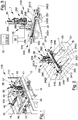
- number 100 indicates, in its entirety, a forming machine for forming trays with reinforced corners that is provided with a frame 101 and with a folding station 110.
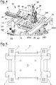
- the machine 100 comprises (in this station 110) a folding unit 1 that can be used to fold flaps L of flanks F of die-cut panels P, a specimen of which can be seen only in figure 5 , to be transformed in the reinforced corners of a tray V, a specimen of which is shown only in figure 6 , where the respective corners may be any one of the three types A, A' and A" of prismatic corners, a plan view of which is shown only in figures 7a)-7b ).
- the first two specimens of corners A and A' have triangular cross-section and the third corner A" has L-shaped cross-section, all the three corners being produced by folding a flap L provided with two weakening lines I on a respective flank F, according to three different ways of forming the respective folding steps, but always according to trajectories T transverse to the direction D.
- the unit 1 comprises a frame 10, delimited, transversally to the direction D, by two side portions 11 and 13 that are arranged transversally to the direction D and are better shown in figure 4 and are connected together through beams 14 and 15, aligned with the direction D and better shown in figure 4 .
- the frame 10 is carried vertically sliding (in figure 1 ) by means of two slide-guide devices 16 and 17, one for each side portion 11 and 13, and engages the folding station 110.
- the frame 10 furthermore supports at least one folding bar 22 directed according to the direction D through the interposition of an actuating unit 20 designed to move the first bar 22 along a curvilinear trajectory T to fold flaps L of a die-cut panel P.
- the actuating unit 20 comprises a first actuating device 24 and a second actuating device 26 carried by the frame 10 and associated with the first bar 22 in order to move this latter so as to generate the trajectory T, which is transverse to the direction D and is schematically shown in figure 2 with a dot dash line.
- each plane curvilinear motion can be subdivided into segments, each of which can be generated by composing adequately modulated rectilinear displacements.
- the first actuating device 24 is provided with a first transmission 240 comprising a first flexible member 242 mechanically coupled to a first rotary motor 244 through a first pulley 246 and mechanically coupled to the first bar 22 in order to move this latter with rectilinear motion, as it will be better explained below.
- the first device 24 comprises a first support member 241 provided with a rectilinear guide 2410 directed transversally to the given direction D and a first slide 2412 coupled to the rectilinear guide 2410 in a freely sliding manner.
- the first slide 2412 carries the first bar 22 through a first bracket 220 coupled to the first flexible member 242 so as to be movable with respect to the first support member 241 through the first rotary motor 244.
- the first flexible member 242 is annular in shape and has a first and a second transport branches 2421 and 2422 that are parallel to the first rectilinear guide 2410, and the first bracket 220 is rigidly coupled to the first transport branch 2421 of the first flexible member 242.
- the first support member 241 has an elongated portion 2414 arranged transversally to the first rectilinear guide 2410, and in particular vertically in figure 1 .
- the elongated portion 2414 is coupled in a sliding manner transversally to the given direction D through a slide-guide device 30; the second device 26 is designed to move the elongated portion 2414 longitudinally with respect to the frame 10 transversally to the first device 24.
- the second device 26 comprises a second rotary motor 260 carried by the frame 10 and a second transmission 262 provided with a second flexible member 264 wound around a second pulley 266 keyed on a drive shaft of the second rotary motor 260; the second flexible member 264 is provided with a first end portion 268 rigidly connected to the first support member 241 for moving along a rectilinear path directed transversally to the rectilinear path of the bracket 220 with respect to the frame 10, and therefore with respect to the frame 101 of the forming machine 1.
- the first actuating device 24 comprises a second slide 2416 coupled to the first linear guide 2410 in a freely sliding manner and carrying a second bar 23 through a second bracket 221 rigidly coupled to the second transport branch 2422 of the first flexible member 242. Therefore, the two slides 2412 and 2416 move symmetrically (travelling equal and opposite spaces in equal times) and transversally to the direction D through the first flexible member 242.
- the folding unit 1 comprises a balancing device 40 comprising a linear actuator 41, whose armour 42 ( figure 1 ) is rigidly connected to the frame 101 of the machine 100 and is arranged above the unit 1, in an intermediate position between the side portions 11 and 13 of the frame 10.
- the actuator 41 is provided with a stem 44 that is aligned with the direction D and has a free end 45 to which an arm 46 is hinged that is, in turn, keyed on the centre of a beam 47 with circular cross-section supported by the frame 101 in a rotating manner around an axis 102, parallel to the direction D through a pair of connecting rods 103 and 104, shown only in figure 4 .
- the balancing device 40 supports the first rectilinear guide 2410, so as to prevent the unit 1 from vertically moving on a plane 12 for feeding the panels P crossing the folding station 110 and extending along the direction D.
- the first rotary motor 244 and the second rotary motor 260 comprises a brushless motor and that the unit 1 comprises a control unit 50, to which the two rotary motors 244 and 260 are electronically connected.
- the choice of this kind of actuation system, and the combination thereof with the unit 50 allows, through a data processing device 52, usually a personal computer or a tablet, to manage, remotely and point-to-point, the movement of the first and of the second flexible members 242 and 264, therefore the position of the bars 22 and 23 in the directions transverse to the direction D and to modulate the movement thereof at will as regards speed and acceleration separately.
- the presence of the data processing device 52 allows to store the settings of the first and the second actuating devices 24 and 26.
- the balancing device 40 may be considered as a safety device, as it ensures that the bars 22 and 23 are always above the plane 12, without interfering with the feeding of the panels P.
- folding unit 1 is clearly apparent from the description above and does not require further explanations.
- the choice of using brushless motors allows to manage, remotely and point-to-point, the movement of the first and of the second flexible members 242 and 264, through a computerized device thanks to the presence of the unit 50. Therefore, thanks to this electronic equipment, it is possible to modulate the movement of the bars 22 and 23 at will as regards speed and acceleration separately, in the directions transverse to the direction D in order to prepare the unit 1 for changing the format of the panels P without the need for accessing the same unit 1 and acting on the settings of the mechanical transport and transmission members.
- the presence of the balancing device ensures that the bars 22 and 23 are always above the plane 12 without interfering with the feeding of the panels P also in the steps of regulating the kinematic and dynamic parameters controlling the operation of the first actuating device 24 and of the second actuating device 26.
- the folding unit 1 is suitable to form each of the three models of reinforced corners A, A' and A", according to pre-set trajectories T followed by the first and the second bars 22 and 23, managing in a combined manner the operation of the first and of the second actuating devices 24 and 26 and, substantially, the rectilinear movement of the first bracket 220 and of the first support member 241 through the activation of the first rotary motor 244 and the second rotary motor 260 according to what illustrated, both during the step of setting (of the folding unit 1) and during the production step.
- the unit 1 allows to provide a folding method for folding die-cut panels P through the use of the forming machine 100 wherein the method comprises a first step of feeding each panel P along the direction D; a second step of folding, in succession, a flap L of each panel P through the bar 22 along the curvilinear trajectory T.
- the second step comprises a third step of actuating a first rotary motor 244 of the first actuating device 24 to move the first bar 22 with rectilinear motion transversally to the direction D through a first transmission 240, comprising a first flexible member 242 mechanically coupled to the first rotary motor 244.
- the method furthermore comprises a fourth step of actuating the second rotary motor 260 of the second actuating device 26 carried by the frame 10 and the second transmission 262 provided with the second flexible member 264 rotoidally coupled to the second rotary motor 260 through the second pulley 266.
- first actuating device 24 and the second actuating device 26 are independent of each other as regards mechanics and actuation allows to perform the second and the fourth steps in an independent way both during the change of the settings for the format change and during the execution of the folding steps for folding the flaps L of the panels P.
- the use of the data processing device 52 of the folding unit 1 allows to prepare the machine 100 for the format change of the panels P practically instantaneously, for instance taking, from a library of information corresponding to a plurality of different formats of panels P of the data processing device 52, a specific piece of information on the regulation of the first and of the second actuating devices 24 and 26, or significantly shortening the step of regulating the unit 1 for the new format, thanks to the possibility of performing the changes starting from a format similar in shape and/or dimensions.
- the fact that the actuating unit 20 is provided with actuating devices dedicated to move each bar 22/23 respectively along distinct directions and electronically controlled through the unit 50, together with the data processing device 52, allows to fold easily panels P of asymmetrical shape, i.e. having asymmetrical portions, in succession, in different times, by means of a single folding unit. This can be done by adapting to each folding step the setting of the actuating unit 20 and therefore of the first and the second actuating devices 24 and 26, through the unit 50 and the processing device 52.
- the unit 1 is a folding unit provided with a simplified mechanical equipment, that can be set differently in real time so as to treat differently distinct portions of the panels P to be folded, and, therefore, to produce trays V with reinforced corners A having different shapes (for instance, although without limitation, as in figure 7 ) for each panel P.
- each folding unit shaped similarly to the unit 1 allows to control the movement of the two bars 22 and 23 along optimized paths so that the folding of the flaps of each die-cut panel P can be easily adjusted and repeated, thus solving the drawbacks of the prior art and thus representing a new and original source of economic interest for the Applicant.
Landscapes
- Making Paper Articles (AREA)
- Bending Of Plates, Rods, And Pipes (AREA)
- Electric Double-Layer Capacitors Or The Like (AREA)
- Auxiliary Devices For And Details Of Packaging Control (AREA)
Claims (11)
- Falteinrichtung (1) umfassend einen Rahmen (10), der sich entlang einer bestimmten Richtung (D) erstreckt und eine erste Faltstange (22) stützt, die durch die Einfügung einer Betätigungseinheit (20) in die bestimmte Richtung (D) ausgerichtet ist; die Betätigungseinheit (20) umfassend eine erste Betätigungsvorrichtung (24) und eine zweite Betätigungsvorrichtung (26), die vom Rahmen (10) getragen wird und der ersten Stange (22) zugeordnet ist, um Letztere entlang einer krummlinigen Bahn (T) zu bewegen, die quer zur bestimmten Richtung (D) verläuft, um Laschen (L) aus einer ausgestanzten Platte (P) zu falten; wobei die erste Betätigungsvorrichtung (24) und die zweite Betätigungsvorrichtung (26) jeweils mit einem ersten Getriebe (240) beziehungsweise einem zweiten Getriebe (262) versehen sind, die mittels eines ersten Drehmotors (244) beziehungsweise eines zweiten Drehmotors (260) betätigt werden, welche mechanisch mit der ersten Stange (22) verbunden sind, um diese in eine geradlinige Bewegung zu versetzen; dadurch gekennzeichnet, dass das erste Getriebe (240) eine erstes flexibles Element (242) umfasst, das mechanisch durch eine erste Rolle (246) mit dem ersten Drehmotor (244) verbunden ist, und dadurch, dass die erste Betätigungsvorrichtung (24) ein erstes Halteelement (241), das mit geradlinigen Führungsmitteln (2410) versehen ist, die quer zur bestimmten Richtung (D) ausgerichtet sind, und einen ersten Schieber (2412), der frei gleitend mit den geradlinigen Führungsmitteln (2410) verbunden ist, umfasst; wobei der erste Schieber (2412) die erste Stange (22) durch einen ersten Halter (220), der mit dem ersten flexiblen Element (242) verbunden ist, trägt, um durch den ersten Drehmotor (244) in Bezug auf das erste Halteelement (241) beweglich zu sein.
- Falteinrichtung nach Anspruch 1, dadurch gekennzeichnet, dass das erste flexible Element (242) ringförmig ist und einen ersten und einen zweiten Transportarm (2421, 2422) parallel zu den ersten geradlinigen Führungsmitteln (2410) aufweist; wobei der erste Halter (220) starr mit dem ersten Transportarm (2421) des ersten flexiblen Elements (242) verbunden ist.
- Falteinrichtung nach einem der Ansprüche 1 bis 2, dadurch gekennzeichnet, dass das erste Halteelement (241) einen längserstreckten Abschnitt (2414) aufweist, der quer zur ersten geradlinigen Führung (2410) angeordnet und durch eine Gleitführungsvorrichtung (30) quer zur bestimmten Richtung (D) gleitend verbunden ist; wobei die zweite Vorrichtung (26) dafür gestaltet ist, den längserstreckten Abschnitt (2414) in Längsrichtung in Bezug auf den Rahmen (10) quer zur ersten Vorrichtung (24) zu bewegen.
- Falteinrichtung nach Anspruch 3, dadurch gekennzeichnet, dass die zweite Vorrichtung (26) einen zweiten Drehmotor (260), der vom Rahmen (10) getragen ist, und ein zweites Getriebe (262), das mit einem zweiten flexiblen Element (264), das durch eine zweite Rolle (266) drehbar mit dem zweiten Drehmotor (260) verbunden und mit einem ersten Endabschnitt (268), der starr mit dem ersten Halteelement (241) verbunden ist, versehen ist, um es in Bezug auf den Rahmen (10) zu bewegen, umfasst.
- Falteinrichtung nach einem der Ansprüche 2 - 4, dadurch gekennzeichnet, dass die erste Betätigungsvorrichtung (24) einen zweiten Schieber (2416) umfasst, der frei gleitend mit den geradlinigen Führungsmitteln (2410) verbunden ist und durch einen zweiten Halter (221), der starr mit dem zweiten Transportarm (2422) des ersten flexiblen Elements (242) verbunden ist, eine zweite Stange (23) trägt.
- Falteinrichtung nach Anspruch 5, dadurch gekennzeichnet, dass sich der längserstreckte Abschnitt (2414) vertikal erstreckt; wobei eine Ausgleichsvorrichtung (40) zwischen dem Rahmen (10) und dem ersten Halteelement (241) angeordnet ist, um die vertikale Bewegung des ersten Halteelements (241) in Kombination mit dem zweiten Drehmotor (260) abzustimmen.
- Falteinrichtung nach einem der Ansprüche 4 bis 6, dadurch gekennzeichnet, dass mindestens entweder der erste Drehmotor (244) und/oder der zweite Drehmotor (260) einen bürstenlosen Motor umfasst.
- Falteinrichtung nach Anspruch 7, dadurch gekennzeichnet, dass er eine Steuervorrichtung (50) umfasst, die sowohl mit dem ersten Drehmotor (244) als auch mit dem zweiten Drehmotor (260) verbunden ist, um die Drehung der ersten beziehungsweise der zweiten Rolle (246, 266) unterschiedlich abzustimmen; wobei eine Datenverarbeitungsvorrichtung (52) bereitgestellt ist, um den ersten Drehmotor (244) und den zweiten Drehmotor (260) unabhängig voneinander in Echtzeit zu steuern.
- Formmaschine (100), die mit einer Faltstation versehen ist, um ausgestanzte Platten (P) zu falten; dadurch gekennzeichnet, dass die Faltstation (110) eine Falteinrichtung (1) gemäß einem der Ansprüche 1 bis 8 umfasst.
- Verfahren zum Falten von ausgestanzten Platten (P) durch eine Formmaschine gemäß Anspruch 9; das Verfahren umfassend einen ersten Schritt des Zuführens der Platte (P) entlang der bestimmten Richtung (D); einen zweiten Schritt des Faltens einer Lasche (L) aus jeder der Platten (P) nacheinander durch die erste Stange entlang der krummlinigen Bahn (T); dadurch gekennzeichnet, dass der erste Schritt einen dritten Schritt des Betätigens des ersten Drehmotors (244) der ersten Betätigungsvorrichtung (24) umfasst, um die erste Stange (22) durch das erste Getriebe (240) umfassend ein erstes flexibles Element (242), das mechanisch mit dem ersten Drehmotor (244) verbunden ist, mit einer geradlinigen Bewegung quer zur bestimmten Richtung (D) zu bewegen, und durch Umfassen eines vierten Schritts des Betätigens des zweiten Drehmotors (260) der zweiten Betätigungsvorrichtung (26), die vom Rahmen (10) getragen ist, und des zweiten Getriebes (262), das mit einem zweiten flexiblen Element (264) versehen ist, das durch eine zweite Rolle (266) drehbar mit dem zweiten Drehmotor (260) verbunden ist.
- Verfahren nach Anspruch 10, dadurch gekennzeichnet, dass der zweite und der vierte Schritt auf Wunsch gleichzeitig ausgeführt werden können, oder nicht.
Priority Applications (3)
| Application Number | Priority Date | Filing Date | Title |
|---|---|---|---|
| RS20191552A RS59620B1 (sr) | 2015-10-14 | 2016-10-12 | Jedinica za savijanje, mašina za oblikovanje, i metoda savijanja |
| HRP20191752TT HRP20191752T1 (hr) | 2015-10-14 | 2016-10-12 | Jedinica za savijanje, stroj za oblikovanje i postupak savijanja |
| PL16801562T PL3362274T3 (pl) | 2015-10-14 | 2016-10-12 | Moduł zginający, formierka oraz sposób zginania |
Applications Claiming Priority (2)
| Application Number | Priority Date | Filing Date | Title |
|---|---|---|---|
| ITUB2015A004680A ITUB20154680A1 (it) | 2015-10-14 | 2015-10-14 | Gruppo di piegatura |
| PCT/IB2016/056102 WO2017064630A1 (en) | 2015-10-14 | 2016-10-12 | Folding unit |
Publications (2)
| Publication Number | Publication Date |
|---|---|
| EP3362274A1 EP3362274A1 (de) | 2018-08-22 |
| EP3362274B1 true EP3362274B1 (de) | 2019-09-04 |
Family
ID=55273365
Family Applications (1)
| Application Number | Title | Priority Date | Filing Date |
|---|---|---|---|
| EP16801562.6A Active EP3362274B1 (de) | 2015-10-14 | 2016-10-12 | Falteinheit, maschine zum formen und verfahren zum falten |
Country Status (8)
| Country | Link |
|---|---|
| EP (1) | EP3362274B1 (de) |
| ES (1) | ES2752562T3 (de) |
| HR (1) | HRP20191752T1 (de) |
| IT (1) | ITUB20154680A1 (de) |
| PL (1) | PL3362274T3 (de) |
| PT (1) | PT3362274T (de) |
| RS (1) | RS59620B1 (de) |
| WO (1) | WO2017064630A1 (de) |
Families Citing this family (1)
| Publication number | Priority date | Publication date | Assignee | Title |
|---|---|---|---|---|
| IT202000001114A1 (it) | 2020-01-22 | 2021-07-22 | Sacmi Packaging Spa | Gruppo di piegatura |
Family Cites Families (6)
| Publication number | Priority date | Publication date | Assignee | Title |
|---|---|---|---|---|
| US4022116A (en) * | 1975-07-14 | 1977-05-10 | International Paper Company | Method and apparatus for folding box flaps |
| ES2024805A6 (es) * | 1990-05-24 | 1992-03-01 | Boix Maquinaria Sa | Plegador de solapas de esquina para basndejas de carton. |
| ES2066680B1 (es) * | 1992-10-26 | 1998-03-16 | Boix Maquinaria Sa | Mecanismo doblador de solapas y conformador de refuerzos en cajas de carton. |
| JP4495850B2 (ja) * | 2000-11-13 | 2010-07-07 | レンゴー株式会社 | 包装箱の形成装置 |
| IT1399831B1 (it) * | 2010-04-27 | 2013-05-03 | Panotec Srl | Macchina per realizzare imballi. |
| ITBO20130108A1 (it) * | 2013-03-13 | 2014-09-14 | L C R Macchine Automatiche S R L | Macchina per la lavorazione di cartone in lastre o simili |
-
2015
- 2015-10-14 IT ITUB2015A004680A patent/ITUB20154680A1/it unknown
-
2016
- 2016-10-12 PL PL16801562T patent/PL3362274T3/pl unknown
- 2016-10-12 HR HRP20191752TT patent/HRP20191752T1/hr unknown
- 2016-10-12 WO PCT/IB2016/056102 patent/WO2017064630A1/en not_active Ceased
- 2016-10-12 PT PT168015626T patent/PT3362274T/pt unknown
- 2016-10-12 EP EP16801562.6A patent/EP3362274B1/de active Active
- 2016-10-12 ES ES16801562T patent/ES2752562T3/es active Active
- 2016-10-12 RS RS20191552A patent/RS59620B1/sr unknown
Non-Patent Citations (1)
| Title |
|---|
| None * |
Also Published As
| Publication number | Publication date |
|---|---|
| ITUB20154680A1 (it) | 2017-04-14 |
| PT3362274T (pt) | 2019-10-09 |
| HRP20191752T1 (hr) | 2019-12-27 |
| PL3362274T3 (pl) | 2019-12-31 |
| EP3362274A1 (de) | 2018-08-22 |
| RS59620B1 (sr) | 2020-01-31 |
| ES2752562T3 (es) | 2020-04-06 |
| WO2017064630A1 (en) | 2017-04-20 |
Similar Documents
| Publication | Publication Date | Title |
|---|---|---|
| KR102677037B1 (ko) | 다수의 엔드-이펙터로써 재료를 핸들링하는 방법 및 장치 | |
| EP3187290B1 (de) | Verfahren zur bearbeitung eines werkstücks mit einer werkzeugmaschine | |
| EP2818437B1 (de) | Transportvorrichtung für flexible Verpackung für Verpackungsmaschinen | |
| EP3262201B1 (de) | Verfahren zur herstellung von motiven auf leder und entsprechende lederstanzmaschine | |
| EP2708309A2 (de) | Laserschneidemaschine und maschinenlesbares medium | |
| CN107282720A (zh) | 一种左右共弯型数控弯管机 | |
| EP2444195A1 (de) | Kombimaschine zum Stanzen und Laserschneiden eines Flachblechmetalls | |
| EP4066959B1 (de) | Federformmaschine | |
| EP3606831B1 (de) | Aufnahme- und ablagestation | |
| WO2017064630A1 (en) | Folding unit | |
| EP1793963B1 (de) | Laserstanzmaschine | |
| US9138843B2 (en) | Handling workpieces at a workpiece support | |
| KR101407519B1 (ko) | 캡슐형 가변축 복합 가공 장치의 스테이지 유닛 | |
| EP3160849A1 (de) | Anlage und verfahren zur herstellung von verpackungen | |
| CN206123643U (zh) | 运动冗余五自由度混联机器人 | |
| RU2741031C2 (ru) | Вращающийся нож машины для производства упаковок и способ использования указанного ножа | |
| WO2012044181A1 (en) | Bending apparatuses, systems and methods | |
| EP1738883B1 (de) | Bearbeitungsmaschine für Pappe | |
| US20260084395A1 (en) | A device for longitudinal processing of a corrugated board web | |
| EP4491296B1 (de) | Werkzeugbewegungsvorrichtung und drahtformmaschine | |
| KR20150010917A (ko) | 레이저 절삭 기계 및 컴퓨터 판독 가능 매체 | |
| CN202934059U (zh) | 一种高精度弹簧机 | |
| EP3880472B1 (de) | Verfahren zum anlernen und/oder betreiben eines kaschierverfahrens und/oder einer kaschiervorrichtung, verfahren zum kaschieren eines folienelements, verfahren zum ein- und umrüsten einer kaschiervorrichtung zum kaschieren eines folienelements, vorrichtung zum kaschieren eines folienelements und teachingstation sowie folienelement | |
| EP4680444A1 (de) | Wasserstrahlschneidsystem | |
| WO2026012615A1 (de) | Vorrichtung und verfahren zur mitlaufenden werkzeugpositionierung linear geförderter artikel der lebensmittelverarbeitenden industrie sowie anordnung und verfahren zum automatischen entfernen mindestens des gabelbeins |
Legal Events
| Date | Code | Title | Description |
|---|---|---|---|
| STAA | Information on the status of an ep patent application or granted ep patent |
Free format text: STATUS: UNKNOWN |
|
| STAA | Information on the status of an ep patent application or granted ep patent |
Free format text: STATUS: THE INTERNATIONAL PUBLICATION HAS BEEN MADE |
|
| PUAI | Public reference made under article 153(3) epc to a published international application that has entered the european phase |
Free format text: ORIGINAL CODE: 0009012 |
|
| STAA | Information on the status of an ep patent application or granted ep patent |
Free format text: STATUS: REQUEST FOR EXAMINATION WAS MADE |
|
| 17P | Request for examination filed |
Effective date: 20180409 |
|
| AK | Designated contracting states |
Kind code of ref document: A1 Designated state(s): AL AT BE BG CH CY CZ DE DK EE ES FI FR GB GR HR HU IE IS IT LI LT LU LV MC MK MT NL NO PL PT RO RS SE SI SK SM TR |
|
| AX | Request for extension of the european patent |
Extension state: BA ME |
|
| DAV | Request for validation of the european patent (deleted) | ||
| DAX | Request for extension of the european patent (deleted) | ||
| GRAP | Despatch of communication of intention to grant a patent |
Free format text: ORIGINAL CODE: EPIDOSNIGR1 |
|
| STAA | Information on the status of an ep patent application or granted ep patent |
Free format text: STATUS: GRANT OF PATENT IS INTENDED |
|
| INTG | Intention to grant announced |
Effective date: 20190408 |
|
| GRAS | Grant fee paid |
Free format text: ORIGINAL CODE: EPIDOSNIGR3 |
|
| GRAA | (expected) grant |
Free format text: ORIGINAL CODE: 0009210 |
|
| STAA | Information on the status of an ep patent application or granted ep patent |
Free format text: STATUS: THE PATENT HAS BEEN GRANTED |
|
| AK | Designated contracting states |
Kind code of ref document: B1 Designated state(s): AL AT BE BG CH CY CZ DE DK EE ES FI FR GB GR HR HU IE IS IT LI LT LU LV MC MK MT NL NO PL PT RO RS SE SI SK SM TR |
|
| REG | Reference to a national code |
Ref country code: GB Ref legal event code: FG4D |
|
| REG | Reference to a national code |
Ref country code: CH Ref legal event code: EP |
|
| REG | Reference to a national code |
Ref country code: AT Ref legal event code: REF Ref document number: 1174787 Country of ref document: AT Kind code of ref document: T Effective date: 20190915 |
|
| REG | Reference to a national code |
Ref country code: HR Ref legal event code: TUEP Ref document number: P20191752 Country of ref document: HR |
|
| REG | Reference to a national code |
Ref country code: DE Ref legal event code: R096 Ref document number: 602016020113 Country of ref document: DE |
|
| REG | Reference to a national code |
Ref country code: IE Ref legal event code: FG4D |
|
| REG | Reference to a national code |
Ref country code: PT Ref legal event code: SC4A Ref document number: 3362274 Country of ref document: PT Date of ref document: 20191009 Kind code of ref document: T Free format text: AVAILABILITY OF NATIONAL TRANSLATION Effective date: 20190920 |
|
| REG | Reference to a national code |
Ref country code: HR Ref legal event code: ODRP Ref document number: P20191752 Country of ref document: HR Payment date: 20191010 Year of fee payment: 4 |
|
| REG | Reference to a national code |
Ref country code: HR Ref legal event code: T1PR Ref document number: P20191752 Country of ref document: HR |
|
| REG | Reference to a national code |
Ref country code: NL Ref legal event code: FP |
|
| REG | Reference to a national code |
Ref country code: LT Ref legal event code: MG4D |
|
| PG25 | Lapsed in a contracting state [announced via postgrant information from national office to epo] |
Ref country code: LT Free format text: LAPSE BECAUSE OF FAILURE TO SUBMIT A TRANSLATION OF THE DESCRIPTION OR TO PAY THE FEE WITHIN THE PRESCRIBED TIME-LIMIT Effective date: 20190904 Ref country code: BG Free format text: LAPSE BECAUSE OF FAILURE TO SUBMIT A TRANSLATION OF THE DESCRIPTION OR TO PAY THE FEE WITHIN THE PRESCRIBED TIME-LIMIT Effective date: 20191204 Ref country code: SE Free format text: LAPSE BECAUSE OF FAILURE TO SUBMIT A TRANSLATION OF THE DESCRIPTION OR TO PAY THE FEE WITHIN THE PRESCRIBED TIME-LIMIT Effective date: 20190904 Ref country code: NO Free format text: LAPSE BECAUSE OF FAILURE TO SUBMIT A TRANSLATION OF THE DESCRIPTION OR TO PAY THE FEE WITHIN THE PRESCRIBED TIME-LIMIT Effective date: 20191204 |
|
| PG25 | Lapsed in a contracting state [announced via postgrant information from national office to epo] |
Ref country code: LV Free format text: LAPSE BECAUSE OF FAILURE TO SUBMIT A TRANSLATION OF THE DESCRIPTION OR TO PAY THE FEE WITHIN THE PRESCRIBED TIME-LIMIT Effective date: 20190904 Ref country code: AL Free format text: LAPSE BECAUSE OF FAILURE TO SUBMIT A TRANSLATION OF THE DESCRIPTION OR TO PAY THE FEE WITHIN THE PRESCRIBED TIME-LIMIT Effective date: 20190904 |
|
| REG | Reference to a national code |
Ref country code: ES Ref legal event code: FG2A Ref document number: 2752562 Country of ref document: ES Kind code of ref document: T3 Effective date: 20200406 |
|
| REG | Reference to a national code |
Ref country code: GR Ref legal event code: EP Ref document number: 20190403676 Country of ref document: GR Effective date: 20200318 |
|
| PG25 | Lapsed in a contracting state [announced via postgrant information from national office to epo] |
Ref country code: RO Free format text: LAPSE BECAUSE OF FAILURE TO SUBMIT A TRANSLATION OF THE DESCRIPTION OR TO PAY THE FEE WITHIN THE PRESCRIBED TIME-LIMIT Effective date: 20190904 Ref country code: EE Free format text: LAPSE BECAUSE OF FAILURE TO SUBMIT A TRANSLATION OF THE DESCRIPTION OR TO PAY THE FEE WITHIN THE PRESCRIBED TIME-LIMIT Effective date: 20190904 |
|
| PG25 | Lapsed in a contracting state [announced via postgrant information from national office to epo] |
Ref country code: SK Free format text: LAPSE BECAUSE OF FAILURE TO SUBMIT A TRANSLATION OF THE DESCRIPTION OR TO PAY THE FEE WITHIN THE PRESCRIBED TIME-LIMIT Effective date: 20190904 Ref country code: IS Free format text: LAPSE BECAUSE OF FAILURE TO SUBMIT A TRANSLATION OF THE DESCRIPTION OR TO PAY THE FEE WITHIN THE PRESCRIBED TIME-LIMIT Effective date: 20200224 Ref country code: SM Free format text: LAPSE BECAUSE OF FAILURE TO SUBMIT A TRANSLATION OF THE DESCRIPTION OR TO PAY THE FEE WITHIN THE PRESCRIBED TIME-LIMIT Effective date: 20190904 Ref country code: CZ Free format text: LAPSE BECAUSE OF FAILURE TO SUBMIT A TRANSLATION OF THE DESCRIPTION OR TO PAY THE FEE WITHIN THE PRESCRIBED TIME-LIMIT Effective date: 20190904 |
|
| REG | Reference to a national code |
Ref country code: CH Ref legal event code: PL |
|
| REG | Reference to a national code |
Ref country code: DE Ref legal event code: R097 Ref document number: 602016020113 Country of ref document: DE |
|
| PLBE | No opposition filed within time limit |
Free format text: ORIGINAL CODE: 0009261 |
|
| STAA | Information on the status of an ep patent application or granted ep patent |
Free format text: STATUS: NO OPPOSITION FILED WITHIN TIME LIMIT |
|
| PG2D | Information on lapse in contracting state deleted |
Ref country code: IS |
|
| PG25 | Lapsed in a contracting state [announced via postgrant information from national office to epo] |
Ref country code: DK Free format text: LAPSE BECAUSE OF FAILURE TO SUBMIT A TRANSLATION OF THE DESCRIPTION OR TO PAY THE FEE WITHIN THE PRESCRIBED TIME-LIMIT Effective date: 20190904 Ref country code: LU Free format text: LAPSE BECAUSE OF NON-PAYMENT OF DUE FEES Effective date: 20191012 Ref country code: CH Free format text: LAPSE BECAUSE OF NON-PAYMENT OF DUE FEES Effective date: 20191031 Ref country code: LI Free format text: LAPSE BECAUSE OF NON-PAYMENT OF DUE FEES Effective date: 20191031 Ref country code: IS Free format text: LAPSE BECAUSE OF FAILURE TO SUBMIT A TRANSLATION OF THE DESCRIPTION OR TO PAY THE FEE WITHIN THE PRESCRIBED TIME-LIMIT Effective date: 20200105 |
|
| 26N | No opposition filed |
Effective date: 20200605 |
|
| PG25 | Lapsed in a contracting state [announced via postgrant information from national office to epo] |
Ref country code: MC Free format text: LAPSE BECAUSE OF FAILURE TO SUBMIT A TRANSLATION OF THE DESCRIPTION OR TO PAY THE FEE WITHIN THE PRESCRIBED TIME-LIMIT Effective date: 20190904 Ref country code: SI Free format text: LAPSE BECAUSE OF FAILURE TO SUBMIT A TRANSLATION OF THE DESCRIPTION OR TO PAY THE FEE WITHIN THE PRESCRIBED TIME-LIMIT Effective date: 20190904 |
|
| REG | Reference to a national code |
Ref country code: HR Ref legal event code: ODRP Ref document number: P20191752 Country of ref document: HR Payment date: 20200923 Year of fee payment: 5 |
|
| PG25 | Lapsed in a contracting state [announced via postgrant information from national office to epo] |
Ref country code: CY Free format text: LAPSE BECAUSE OF FAILURE TO SUBMIT A TRANSLATION OF THE DESCRIPTION OR TO PAY THE FEE WITHIN THE PRESCRIBED TIME-LIMIT Effective date: 20190904 |
|
| PG25 | Lapsed in a contracting state [announced via postgrant information from national office to epo] |
Ref country code: MT Free format text: LAPSE BECAUSE OF FAILURE TO SUBMIT A TRANSLATION OF THE DESCRIPTION OR TO PAY THE FEE WITHIN THE PRESCRIBED TIME-LIMIT Effective date: 20190904 Ref country code: HU Free format text: LAPSE BECAUSE OF FAILURE TO SUBMIT A TRANSLATION OF THE DESCRIPTION OR TO PAY THE FEE WITHIN THE PRESCRIBED TIME-LIMIT; INVALID AB INITIO Effective date: 20161012 |
|
| REG | Reference to a national code |
Ref country code: HR Ref legal event code: ODRP Ref document number: P20191752 Country of ref document: HR Payment date: 20210921 Year of fee payment: 6 |
|
| PG25 | Lapsed in a contracting state [announced via postgrant information from national office to epo] |
Ref country code: MK Free format text: LAPSE BECAUSE OF FAILURE TO SUBMIT A TRANSLATION OF THE DESCRIPTION OR TO PAY THE FEE WITHIN THE PRESCRIBED TIME-LIMIT Effective date: 20190904 |
|
| REG | Reference to a national code |
Ref country code: AT Ref legal event code: UEP Ref document number: 1174787 Country of ref document: AT Kind code of ref document: T Effective date: 20190904 |
|
| REG | Reference to a national code |
Ref country code: HR Ref legal event code: ODRP Ref document number: P20191752 Country of ref document: HR Payment date: 20220921 Year of fee payment: 7 |
|
| REG | Reference to a national code |
Ref country code: HR Ref legal event code: ODRP Ref document number: P20191752 Country of ref document: HR Payment date: 20231003 Year of fee payment: 8 |
|
| REG | Reference to a national code |
Ref country code: HR Ref legal event code: ODRP Ref document number: P20191752 Country of ref document: HR Payment date: 20241002 Year of fee payment: 9 |
|
| PGFP | Annual fee paid to national office [announced via postgrant information from national office to epo] |
Ref country code: PT Payment date: 20250923 Year of fee payment: 10 |
|
| PGFP | Annual fee paid to national office [announced via postgrant information from national office to epo] |
Ref country code: TR Payment date: 20250925 Year of fee payment: 10 |
|
| PGFP | Annual fee paid to national office [announced via postgrant information from national office to epo] |
Ref country code: RS Payment date: 20250917 Year of fee payment: 10 |
|
| REG | Reference to a national code |
Ref country code: HR Ref legal event code: ODRP Ref document number: P20191752 Country of ref document: HR Payment date: 20251001 Year of fee payment: 10 |
|
| PGFP | Annual fee paid to national office [announced via postgrant information from national office to epo] |
Ref country code: NL Payment date: 20251026 Year of fee payment: 10 |
|
| PGFP | Annual fee paid to national office [announced via postgrant information from national office to epo] |
Ref country code: DE Payment date: 20251029 Year of fee payment: 10 |
|
| PGFP | Annual fee paid to national office [announced via postgrant information from national office to epo] |
Ref country code: GB Payment date: 20251027 Year of fee payment: 10 |
|
| PGFP | Annual fee paid to national office [announced via postgrant information from national office to epo] |
Ref country code: AT Payment date: 20251029 Year of fee payment: 10 |
|
| PGFP | Annual fee paid to national office [announced via postgrant information from national office to epo] |
Ref country code: FI Payment date: 20251027 Year of fee payment: 10 Ref country code: IT Payment date: 20251017 Year of fee payment: 10 |
|
| PGFP | Annual fee paid to national office [announced via postgrant information from national office to epo] |
Ref country code: HR Payment date: 20251001 Year of fee payment: 10 Ref country code: FR Payment date: 20251027 Year of fee payment: 10 |
|
| PGFP | Annual fee paid to national office [announced via postgrant information from national office to epo] |
Ref country code: GR Payment date: 20251029 Year of fee payment: 10 Ref country code: BE Payment date: 20251027 Year of fee payment: 10 |
|
| PGFP | Annual fee paid to national office [announced via postgrant information from national office to epo] |
Ref country code: IE Payment date: 20251027 Year of fee payment: 10 |
|
| PGFP | Annual fee paid to national office [announced via postgrant information from national office to epo] |
Ref country code: PL Payment date: 20251118 Year of fee payment: 10 |
|
| PGFP | Annual fee paid to national office [announced via postgrant information from national office to epo] |
Ref country code: ES Payment date: 20251103 Year of fee payment: 10 |