EP3362133B1 - Atemschutzhaube - Google Patents
Atemschutzhaube Download PDFInfo
- Publication number
- EP3362133B1 EP3362133B1 EP16788173.9A EP16788173A EP3362133B1 EP 3362133 B1 EP3362133 B1 EP 3362133B1 EP 16788173 A EP16788173 A EP 16788173A EP 3362133 B1 EP3362133 B1 EP 3362133B1
- Authority
- EP
- European Patent Office
- Prior art keywords
- tube
- holes
- volume
- hood according
- hood
- Prior art date
- Legal status (The legal status is an assumption and is not a legal conclusion. Google has not performed a legal analysis and makes no representation as to the accuracy of the status listed.)
- Active
Links
Images


Classifications
-
- A—HUMAN NECESSITIES
- A62—LIFE-SAVING; FIRE-FIGHTING
- A62B—DEVICES, APPARATUS OR METHODS FOR LIFE-SAVING
- A62B17/00—Protective clothing affording protection against heat or harmful chemical agents or for use at high altitudes
- A62B17/04—Hoods
-
- A—HUMAN NECESSITIES
- A62—LIFE-SAVING; FIRE-FIGHTING
- A62B—DEVICES, APPARATUS OR METHODS FOR LIFE-SAVING
- A62B19/00—Cartridges with absorbing substances for respiratory apparatus
-
- A—HUMAN NECESSITIES
- A62—LIFE-SAVING; FIRE-FIGHTING
- A62B—DEVICES, APPARATUS OR METHODS FOR LIFE-SAVING
- A62B7/00—Respiratory apparatus
- A62B7/10—Respiratory apparatus with filter elements
-
- A—HUMAN NECESSITIES
- A61—MEDICAL OR VETERINARY SCIENCE; HYGIENE
- A61M—DEVICES FOR INTRODUCING MEDIA INTO, OR ONTO, THE BODY; DEVICES FOR TRANSDUCING BODY MEDIA OR FOR TAKING MEDIA FROM THE BODY; DEVICES FOR PRODUCING OR ENDING SLEEP OR STUPOR
- A61M16/00—Devices for influencing the respiratory system of patients by gas treatment, e.g. ventilators; Tracheal tubes
- A61M16/06—Respiratory or anaesthetic masks
- A61M16/0605—Means for improving the adaptation of the mask to the patient
- A61M16/0627—Means for improving the adaptation of the mask to the patient with sealing means on a part of the body other than the face, e.g. helmets, hoods or domes
-
- A—HUMAN NECESSITIES
- A61—MEDICAL OR VETERINARY SCIENCE; HYGIENE
- A61M—DEVICES FOR INTRODUCING MEDIA INTO, OR ONTO, THE BODY; DEVICES FOR TRANSDUCING BODY MEDIA OR FOR TAKING MEDIA FROM THE BODY; DEVICES FOR PRODUCING OR ENDING SLEEP OR STUPOR
- A61M16/00—Devices for influencing the respiratory system of patients by gas treatment, e.g. ventilators; Tracheal tubes
- A61M16/22—Carbon dioxide-absorbing devices ; Other means for removing carbon dioxide
-
- A—HUMAN NECESSITIES
- A61—MEDICAL OR VETERINARY SCIENCE; HYGIENE
- A61M—DEVICES FOR INTRODUCING MEDIA INTO, OR ONTO, THE BODY; DEVICES FOR TRANSDUCING BODY MEDIA OR FOR TAKING MEDIA FROM THE BODY; DEVICES FOR PRODUCING OR ENDING SLEEP OR STUPOR
- A61M2202/00—Special media to be introduced, removed or treated
- A61M2202/02—Gases
- A61M2202/0208—Oxygen
-
- A—HUMAN NECESSITIES
- A62—LIFE-SAVING; FIRE-FIGHTING
- A62B—DEVICES, APPARATUS OR METHODS FOR LIFE-SAVING
- A62B7/00—Respiratory apparatus
- A62B7/02—Respiratory apparatus with compressed oxygen or air
-
- A—HUMAN NECESSITIES
- A62—LIFE-SAVING; FIRE-FIGHTING
- A62B—DEVICES, APPARATUS OR METHODS FOR LIFE-SAVING
- A62B7/00—Respiratory apparatus
- A62B7/14—Respiratory apparatus for high-altitude aircraft
-
- B—PERFORMING OPERATIONS; TRANSPORTING
- B63—SHIPS OR OTHER WATERBORNE VESSELS; RELATED EQUIPMENT
- B63C—LAUNCHING, HAULING-OUT, OR DRY-DOCKING OF VESSELS; LIFE-SAVING IN WATER; EQUIPMENT FOR DWELLING OR WORKING UNDER WATER; MEANS FOR SALVAGING OR SEARCHING FOR UNDERWATER OBJECTS
- B63C11/00—Equipment for dwelling or working underwater; Means for searching for underwater objects
- B63C11/02—Divers' equipment
- B63C11/18—Air supply
- B63C11/22—Air supply carried by diver
- B63C11/24—Air supply carried by diver in closed circulation
Definitions
- the invention relates to a respiratory protection hood.
- the invention more particularly relates to a respiratory protection hood comprising a sealed flexible envelope intended to be threaded onto the head of a user, the flexible envelope being provided with a transparent window and comprising, in its lower part, an element of rigid base for being arranged around the neck of the user, the base element comprising a pressure oxygen tank provided with a calibrated outlet opening opening into the internal volume of the flexible envelope and a device for capturing at least a portion of the carbon dioxide exhaled by the user to purify the breathable gas within the hood.
- the invention relates in particular to respiratory protection equipment operating in a closed circuit.
- This type of closed circuit operation makes it possible to minimize the bulk and weight of breathing equipment.
- the equipment must include a sealed volume (hood shell) around the head of the user in which oxygen is released and the carbon dioxide concentration maintained at a determined low value.
- the percentage of carbon dioxide must remain below 4% (at sea level).
- one solution is to provide in the hood a device for capturing carbon dioxide, for example a carbon dioxide (CO2) absorption cartridge.
- a device for capturing carbon dioxide for example a carbon dioxide (CO2) absorption cartridge.
- the radial structure cartridges are known for their purification efficiency and the low pressure loss they generate. Radial cartridges optimize the residence time of the gas in the cartridge (and thus the efficiency of purification). However, this type of cartridge is generally very bulky and not very ergonomic. (see for example US2010242966A or US7520280 ).
- these cartridges require to have a gas collector and a gas diffuser sections sufficient to limit the pressure drop.
- the need to provide a sufficient volume of filter material can quickly lead to a consequent cartridge outer diameter.
- the length of the known devices although beneficial with respect to the residence time of the gas and the pressure drop, makes the ergonomic integration of the cartridge into respiratory protection equipment more difficult.
- An object of the present invention is to overcome all or part of the disadvantages of the prior art noted above.
- the hood according to the invention is essentially characterized in that the carbon dioxide capture device comprises a carbon dioxide adsorption cartridge.
- radially structured carbon composition comprising a tubular body extending in a longitudinal direction and housing a volume of carbon dioxide absorbing material, said structure of the cartridge comprising a perforated tube disposed around the volume of absorbent material and according to the longitudinal direction to allow the transiting of air to be purified radially in the volume of absorbent material, that is to say perpendicular to the longitudinal direction, and in that at least a portion of the perforated tube disposed around the volume of absorbent material communicates directly with the internal volume of the hood, that is to say that at least a portion of the openwork tube is not surrounded an additional outer full wall defining a diffuser volume around the perforated tube.
- the invention may also relate to any alternative device or method comprising any combination of the above or below features.
- the non-limiting example of a respiratory protection hood shown in figure 1 comprises a sealed flexible envelope 2 intended to be threaded on the head of a user.
- Preferably 2 flexible is provided with a transparent window 20 and comprising, in its lower part, a rigid base element 3, 4 to be arranged around the neck of the user.
- the flexible envelope 2 waterproof is composed for example of a waterproof fireproof or waterproof textile.
- a waterproof fireproof or waterproof textile for example it is a synthetic fiber textile low combustibility.
- This envelope 2 is intended to be threaded on the user's head to isolate the user's head from the outside environment and to integrate the features described below.
- the base of the flexible envelope 2 may comprise a flexible diaphragm or a tight collar 12 to be mounted around the neck of a user.
- this lower flange 12 comprises a perforated plastic sheet (for example a polymer, especially a self-extinguishing polymer such as Neoprene or silicone) to allow the user's head to pass elastically and then tighten his neck thereafter.
- the lower hole for the head can be adapted to any neck perimeter between 28 and 42cm for example.
- the basic element 3, 4 comprising a reservoir 3 of pressurized oxygen provided with a calibrated outlet orifice 7 opening into the internal volume of the flexible envelope 2 and a device for capturing at least a portion of the carbon dioxide expired by the user.
- the CO2 capture device is intended to purify the breathable gas within the hood 2 to maintain the CO2 level below a determined threshold.
- the basic element 3, 4 may possibly be in at least two articulated parts (articulation 5).
- the CO2 capture device comprises a cartridge 4 for adsorbing carbon dioxide.
- the cartridge 4 comprises a tubular body extending in a longitudinal direction A and housing a volume 8 of carbon dioxide absorbing material.
- This cartridge 4 has a radial structure. That is to say, the structure of the cartridge 4 comprising a perforated tube 9 disposed around the volume 8 of absorbent material and along the direction A longitudinal to allow the transiting of air to be purified radially in the volume 8 of absorbent material. That is, the gas to be purified passes through the filter cartridge perpendicular to the longitudinal direction A.
- At least a portion of the perforated tube 9 disposed around the volume of absorbent material communicates directly with the internal volume of the hood 2. That is to say that at least a portion of the perforated tube 9 (that is to say the perforated wall) is not surrounded by a supplementary outer wall full delimiting a diffuser volume around the openwork tube 9.
- This structure improves the mass, the volume and the operation of the hood and in particular its system of capturing CO2.
- the radial CO2 absorption cartridges comprise radially from the inside to the outside: of a central core collecting the purified gas, a mass of CO2 adsorbent material disposed around the central core and disposed in a wall perforated tubular, an outer solid wall disposed around the perforated tubular wall.
- the gas to be purified enters one end of the cartridge and circulates in the space (called “distributor” or “diffuser") between the outer solid wall and the perforated tubular wall.
- the gas to be purified between radially in the adsorption material of CO2 (via all of the perforated wall) and purified spring in the central core (via holes). That is, the central core forms a purified gas manifold to an outlet at one end of the cartridge.
- the positions of the purified gas manifold and the distributor may be interchanged (that is, the gas enters the central core and the cartridge and emerges from the periphery while radially passing from the inside to the outside instead of the opposite).
- the outer wall delimiting the distributor is omitted. This reduces the volume and mass of the device for its integration into a hood. In particular, this structure, without impairing the efficiency of the device allows for example to reduce the outer diameter of the cartridge by about 20mm (typically 90mm total in known solutions).
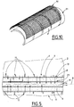
- the figure 5 illustrates an exemplary embodiment explaining this structure.
- the cartridge 4 comprises a perforated tube structure 9.
- This perforated tube comprises an outer wall 19, for example cylindrical, perforated and an inner wall 29 perforated, for example cylindrical and concentric.
- the volume 8 of CO2 absorbing material is disposed and maintained between the inner and outer walls 29 and 19.
- the inner wall 29 communicates with a central volume 10 forming a purified gas evacuation path (see also figure 9 ).
- the perforated outer wall 19 communicates directly with the gas in the casing 2.
- the gas path is shown schematically in FIG. figure 5 via arrows.
- the peripheral surface of the perforated tube 9 may comprise one or more projections 11 which extend radially outwards of the perforated tube 9 with respect to the axis A.
- projections 11 form "spacers" to prevent the flexible envelope 2 or the skin of the user does not obstruct the orifices of the perforated tube 9 by preventing a sealed contact against the perforated wall 19.
- projections 11 also make it possible to prevent the user's skin from coming into contact with the grid containing the CO2 adsorbent material 8 since, generally, the CO 2 fixation reaction is exothermic (the temperature of the cartridge can reach 40 ° C. C which would be uncomfortable)
- the projections 11 extend radially with respect to the longitudinal axis A with a height of, for example, between 1 mm and 5 mm relative to the remainder of the peripheral surface of the perforated tube 9.
- the projections 11 are preferably distributed along the longitudinal direction A.
- the projections 11 may be spaced apart along the longitudinal direction A by a distance of, for example, between 1 mm and 50 mm .
- the projections 11 may be distributed over at least a portion and preferably over the entire circumference of the perforated tube 9.
- the projections 11 may form longitudinal ribs parallel to the longitudinal axis A of the perforated tube 9.
- the projections 11 may form transverse ribs (rings) perpendicular to the longitudinal axis A of the perforated tube 9.
- the projections 11 may be discrete studs distributed on the perforated wall 19.
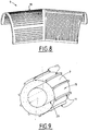
- the reservoir 3 and / or the cartridge 4 and thus the perforated tube 9 can be bent to improve its integration around the head or neck of the user.
- This bending can be continuous (cf. figure 6 and 7 ) or obtained by rectilinear portions assembled with an angle (cf. figure 8 ).
- the filter cartridge 4 is rectilinear (cylindrical tube whose longitudinal direction A is rectilinear, that is to say not curved).
- the oxygen reservoir 3 is preferably bent (curved longitudinal axis).
- the CO2 adsorbent material 8 may comprise, for example, soda lime (Ca (OH) 2 ) or lithium hydroxide (LiOH). These materials both react with CO 2 to generate a carbonate compound, water and heat.
- the material 8 is housed in the perforated tube 9 and maintained in the latter via plugs mounted at the ends of the tube 9.
- the cap of the radial cartridge may be a simple plug or may have a function of tamping the material 8 with metal springs or deformable plastic part under stress.
- FIGS. 3 and 4 schematically illustrate a possible arrangement of the breathing gas generating system in the hood 2.
- outlet port 7 of the tubular oxygen tank 3 and the filtered air outlet 6 of the filter cartridge 4 may be arranged relatively (in particular concentrically and coaxially) to form a venturi device.
- the figure 4 schematizes gas flows via arrows.
- Oxygen is supplied by the oxygen reservoir 3 to the venturi which then generates a suction through of the filter cartridge 4.
- the breathable mixture enriched with oxygen is delivered in the flexible envelope 2.
- This venturi device thus makes it possible to use the expansion energy of the gas supplied by the tank 3 under pressure to create a recirculation stream through the filter cartridge 4 (soda lime or lithium hydroxide).
- the venturi has a driving ratio (suction flow / injected flow rate) of between 10 and 20 over the injected flow rate range of 1 to 5 liters per minute, for example.
- the perforated tube 9 containing the filtering entity 8 preferably has a grid-like structure (plastic or metal or other).
- this structure can be a structure of the type of a rigid grid provided with circular holes.
- this structure may be a structure of the type of a rigid grid provided with holes in the form of grooves (longitudinal, see left-hand part and / or transversal part-right part).
- This structure 9 may for example be molded.
- the figure 10 illustrates another embodiment of the perforated tube 9.
- This may be composed of a basic structure 91 comprising a skeleton covered with a perforated sheet 90, in particular a perforated plastic sheet 90 fixed to the base structure 91.
- the basic structure 91 is made for example by plastic injection.
- the basic structure 91 can also incorporate the projections ("spacers").
- the roasting function (perforated wall provided with a gas passage opening) can be achieved by a plastic sheet 90 having a structure close to that of a mosquito net (made of polyamide with openings of size between 20 and 200 ⁇ m ).
- the perforated tube 9 preferably comprises a plurality of openings provided for the passage of gas, said orifices having surfaces between 3.14 mm 2 and 600 mm 2 .
- the low value of 3.14 mm 2 may correspond to the case where the cartridge will have a multitude of circular orifices of radius 1 mm.
- the high value of 600 mm 2 may correspond to the case where the structure of the tube would only skeleton for a leaf-like screen affixed to this skeleton structure. This skeleton would for example have openings (rectangular or otherwise) of size for example 6x100mm 2 .
- the radial geometry of the cartridge 4 makes it possible to maximize the length of the volume of CO2 adsorbent material 8 and thus makes it possible to reduce the height of the porous entity bed to be crossed. This makes it possible to reduce the outside diameter of the cartridge 4 by improving the residence time and the pressure drop of the gas to be purified. This is thus compatible with the storage space targeted for this type of equipment in aircraft.
Landscapes
- Health & Medical Sciences (AREA)
- General Health & Medical Sciences (AREA)
- Business, Economics & Management (AREA)
- Emergency Management (AREA)
- Pulmonology (AREA)
- Toxicology (AREA)
- Gas Separation By Absorption (AREA)
- Solid-Sorbent Or Filter-Aiding Compositions (AREA)
- Respiratory Apparatuses And Protective Means (AREA)
Claims (14)
- Atemschutzhaube, umfassend eine dichte flexible Hülle (2), dazu bestimmt, um über den Kopf eines Benutzers gezogen zu werden, wobei die flexible Hülle mit einem transparenten Fenster (20) ausgestattet ist und in ihrem unteren Teil ein starres Basiselement (3, 4) umfasst, dazu bestimmt, um den Hals des Benutzers angeordnet zu sein, wobei das Basiselement (3, 4) einen Sauerstoffbehälter (3) unter Druck umfasst, der mit einer kalibrierten Ausgangsöffnung (7) ausgestattet ist, die in das innere Volumen der flexiblen Hülle (2) mündet, und eine Vorrichtung zum Einfangen von mindestens einem Teil des Kohlendioxids, das vom Benutzer ausgeatmet wird, um das atembare Gas innerhalb der Haube (2) zu reinigen, dadurch gekennzeichnet, dass die Vorrichtung zum Einfangen des Kohlendioxids eine Patrone (4) zur Adsorption des Kohlendioxids mit radialer Struktur umfasst, umfassend einen rohrförmigen Körper, der sich in eine Längsrichtung (A) erstreckt und ein Volumen (8) aus absorbierendem Material des Kohlendioxids beherbergt, wobei die Struktur der Patrone (4) ein durchbrochenes Rohr (9) umfasst, das um das Volumen (8) aus absorbierendem Material angeordnet ist und sich in die Längsrichtung (A) erstreckt, um die Übertragung von zu reinigender Luft radial in das Volumen (8) aus absorbierendem Material, d. h. senkrecht zur Längsrichtung (A) zu ermöglichen, und dadurch, dass mindestens ein Teil des durchbrochenen Rohrs (9), das um das Volumen aus absorbierendem Material angeordnet ist, direkt mit dem inneren Volumen der Haube (2) kommuniziert, d. h., dass mindestens ein Teil des durchbrochenen Rohrs (9) nicht von einer massiven zusätzlichen äußeren Wand umgeben ist, die ein Verteilervolumen um das durchbrochene Rohr (9) begrenzt.
- Haube nach Anspruch 1, dadurch gekennzeichnet, dass das durchbrochene Rohr (9) eine durchbrochene äußere Wand (19) und eine durchbrochene innere Wand (29) umfasst, wobei das Volumen (8) aus absorbierendem Material zwischen der inneren (29) und der äußeren Wand (19) angeordnet ist.
- Haube nach Anspruch 2, dadurch gekennzeichnet, dass die gereinigte Luft, die in das Volumen (8) aus absorbierendem Material übertragen wurde, in einem Sammelvolumen (10) von gereinigter Luft gesammelt wird, wobei mindestens ein Teil des Sammelvolumens (10) von gereinigter Luft von der inneren Wand (29) des durchbrochenen Rohrs begrenzt wird.
- Haube nach einem der Ansprüche 1 bis 3, dadurch gekennzeichnet, dass mindestens ein Teil der peripheren Oberfläche des durchbrochenen Rohrs (9) Vorsprünge (11) umfasst, die sich radial hin zur Außenseite des durchbrochenen Rohrs (9) mit Bezug auf die Längsachse (A) erstrecken, um zu vermeiden, dass die flexible Hülle (2) oder die Haut des Benutzers die Öffnungen des durchbrochenen Rohrs (9) blockieren.
- Haube nach Anspruch 4, dadurch gekennzeichnet, dass sich die Vorsprünge (11) radial mit Bezug auf die Längsachse (A) mit einer Höhe erstrecken, die zwischen 1 und 5 mm mit Bezug auf den Rest der peripheren Oberfläche des durchbrochenen Rohrs (9) enthalten ist.
- Haube nach Anspruch 4 oder 5, dadurch gekennzeichnet, dass das Rohr (9) Vorsprünge (11) umfasst, die entlang der Längsrichtung (A) verteilt sind, wobei die Vorsprünge (11) voneinander in der Längsrichtung (A) um eine Distanz beabstandet sind, die zwischen 10 mm und 50 mm enthalten ist.
- Haube nach einem der Ansprüche 4 bis 6, dadurch gekennzeichnet, dass das Rohr (9) Vorsprünge (11) umfasst, die auf mindestens einem Teil und vorzugsweise auf seinem Umfang verteilt sind.
- Haube nach einem der Ansprüche 4 bis 7, dadurch gekennzeichnet, dass das Rohr (9) Vorsprünge (11) umfasst, die Längsrippen bilden, die parallel zur Längsachse (A) sind.
- Haube nach einem der Ansprüche 4 bis 8, dadurch gekennzeichnet, dass das Rohr (9) Vorsprünge (11) umfasst, die Querrippen bilden, die senkrecht zur Längsachse (A) sind.
- Haube nach einem der Ansprüche 1 bis 9, dadurch gekennzeichnet, dass das durchbrochene Rohr (9) eine Vielzahl von Öffnungen umfasst, die für den Durchgang von Gas vorgesehen sind, wobei die Öffnungen Oberflächen aufweisen, die zwischen 3,14 mm2 und 600 mm2 enthalten sind.
- Haube nach einem der Ansprüche 1 bis 10, dadurch gekennzeichnet, dass das durchbrochene Rohr (9) auf seiner Oberfläche eine Vielzahl von kreisförmigen und/oder länglichen und/oder trapezförmigen Öffnungen umfasst, wobei die länglichen Öffnungen parallel oder senkrecht zur Längsrichtung (A) sind.
- Haube nach einem der Ansprüche 1 bis 11, dadurch gekennzeichnet, dass das durchbrochene Rohr (9) aus einer vergitterten metallischen oder Kunststoffstruktur zusammengesetzt ist.
- Haube nach einem der Ansprüche 1 bis 12, dadurch gekennzeichnet, dass das durchbrochene Rohr (9) aus einer Basisstruktur (91) zusammengesetzt ist, umfassend ein Gerüst, das mit einer durchbrochenen Folie (90), insbesondere einer durchbrochenen Kunststofffolie (90) bedeckt ist, die auf der Basisstruktur (91) fixiert ist.
- Haube nach Anspruch 13, dadurch gekennzeichnet, dass die durchbrochene Folie (90) aus Kunststoffmaterial ist und auf die Basisstruktur (91) geklebt oder überformt ist.
Applications Claiming Priority (2)
| Application Number | Priority Date | Filing Date | Title |
|---|---|---|---|
| FR1559783A FR3042421B1 (fr) | 2015-10-15 | 2015-10-15 | Cagoule de protection respiratoire |
| PCT/FR2016/052553 WO2017064393A1 (fr) | 2015-10-15 | 2016-10-05 | Cagoule de protection respiratoire |
Publications (2)
| Publication Number | Publication Date |
|---|---|
| EP3362133A1 EP3362133A1 (de) | 2018-08-22 |
| EP3362133B1 true EP3362133B1 (de) | 2019-05-15 |
Family
ID=54545372
Family Applications (1)
| Application Number | Title | Priority Date | Filing Date |
|---|---|---|---|
| EP16788173.9A Active EP3362133B1 (de) | 2015-10-15 | 2016-10-05 | Atemschutzhaube |
Country Status (4)
| Country | Link |
|---|---|
| US (1) | US11154733B2 (de) |
| EP (1) | EP3362133B1 (de) |
| FR (1) | FR3042421B1 (de) |
| WO (1) | WO2017064393A1 (de) |
Families Citing this family (1)
| Publication number | Priority date | Publication date | Assignee | Title |
|---|---|---|---|---|
| FR3149212A1 (fr) * | 2023-06-02 | 2024-12-06 | L'air Liquide, Societe Anonyme Pour L'etude Et L'exploitation Des Procedes Georges Claude | Cartouche de captation de CO2 |
Family Cites Families (9)
| Publication number | Priority date | Publication date | Assignee | Title |
|---|---|---|---|---|
| FR2582524B1 (fr) * | 1985-05-31 | 1989-01-13 | Air Liquide | Cagoule de protection contre les fumees et l'hypoxie |
| FR2634130B1 (fr) * | 1988-07-12 | 1991-07-05 | Bertin & Cie | Appareil respiratoire autonome de secours |
| US5495847A (en) * | 1995-05-17 | 1996-03-05 | Hu; Wei | Survival hood |
| US5724958A (en) * | 1996-05-28 | 1998-03-10 | M.E.T.A. Research Inc. | Breathing hood |
| DE19832000C1 (de) * | 1998-07-16 | 1999-11-04 | Draeger Aerospace Gmbh | Fluchthaube |
| US7520280B2 (en) | 2003-04-08 | 2009-04-21 | William Gordon | Rebreather apparatus |
| ITMI20080396U1 (it) * | 2008-12-03 | 2010-06-03 | Starmed S P A Ora Intersurgical S P A | Struttura di casco per la ventilazione non invasiva di pazienti. |
| US8272381B2 (en) * | 2009-03-25 | 2012-09-25 | Johnson Charles L | Closed circuit rebreather |
| FR3024370B1 (fr) * | 2014-08-01 | 2016-07-22 | Air Liquide | Cagoule de protection respiratoire |
-
2015
- 2015-10-15 FR FR1559783A patent/FR3042421B1/fr active Active
-
2016
- 2016-10-05 WO PCT/FR2016/052553 patent/WO2017064393A1/fr not_active Ceased
- 2016-10-05 US US15/768,369 patent/US11154733B2/en active Active
- 2016-10-05 EP EP16788173.9A patent/EP3362133B1/de active Active
Non-Patent Citations (1)
| Title |
|---|
| None * |
Also Published As
| Publication number | Publication date |
|---|---|
| US20180296863A1 (en) | 2018-10-18 |
| FR3042421A1 (fr) | 2017-04-21 |
| FR3042421B1 (fr) | 2018-10-26 |
| EP3362133A1 (de) | 2018-08-22 |
| US11154733B2 (en) | 2021-10-26 |
| WO2017064393A1 (fr) | 2017-04-20 |
Similar Documents
| Publication | Publication Date | Title |
|---|---|---|
| US20120187036A1 (en) | Water Filter With Inwardly Sloping Top | |
| US5545315A (en) | Water filtering and purifying apparatus | |
| US7255094B2 (en) | Fuel vapor recovery canister | |
| TWI398591B (zh) | Pipeline filter | |
| US20160067648A1 (en) | Air Filter for the Interior Air of Cabins of Vehicles, Agricultural, Construction, and Work Machines | |
| WO2008079533A2 (en) | Fuel vapor recovery canister | |
| CN106662263A (zh) | 具有压力释放阀的串联可倾卸式燃料系统灰尘过滤器 | |
| US20120097675A1 (en) | Closure device for controlling evaporative emissions from a fuel tank | |
| WO2017064393A1 (fr) | Cagoule de protection respiratoire | |
| TWI408106B (zh) | 淨水濾心以及淨水器 | |
| KR20190004800A (ko) | 개선된 충전 특성을 갖는 자동차의 탱크 환기장치용 연료 증기 필터 | |
| WO2017122746A1 (ja) | 浄水カートリッジ | |
| US20120145620A1 (en) | Filter with Dissolvable Seal | |
| WO2000009449A2 (en) | Portable water filtration system | |
| US20230166134A1 (en) | Filter material and personal protective means based thereon | |
| CN211595223U (zh) | 水过滤器及具有其的冰箱 | |
| CN217041867U (zh) | 抑菌抗病毒的复合过滤器 | |
| CN207062007U (zh) | 净水滤芯 | |
| JP6557570B2 (ja) | 流体フィルター | |
| CN219596092U (zh) | 一种用于油箱注油口的过滤器 | |
| WO2016074217A1 (en) | Adjustable voc/formaldehyde co-absorbing usable mask cartirdge and canister | |
| CN210206201U (zh) | 一种除雾器滤芯 | |
| KR20100133121A (ko) | 필터 어셈블리 | |
| CN108083386A (zh) | 一种航空专用空气净水器 | |
| CN208436501U (zh) | 一种卡头式密封防自漏滤芯结构 |
Legal Events
| Date | Code | Title | Description |
|---|---|---|---|
| STAA | Information on the status of an ep patent application or granted ep patent |
Free format text: STATUS: UNKNOWN |
|
| STAA | Information on the status of an ep patent application or granted ep patent |
Free format text: STATUS: THE INTERNATIONAL PUBLICATION HAS BEEN MADE |
|
| PUAI | Public reference made under article 153(3) epc to a published international application that has entered the european phase |
Free format text: ORIGINAL CODE: 0009012 |
|
| STAA | Information on the status of an ep patent application or granted ep patent |
Free format text: STATUS: REQUEST FOR EXAMINATION WAS MADE |
|
| 17P | Request for examination filed |
Effective date: 20180515 |
|
| AK | Designated contracting states |
Kind code of ref document: A1 Designated state(s): AL AT BE BG CH CY CZ DE DK EE ES FI FR GB GR HR HU IE IS IT LI LT LU LV MC MK MT NL NO PL PT RO RS SE SI SK SM TR |
|
| AX | Request for extension of the european patent |
Extension state: BA ME |
|
| RIN1 | Information on inventor provided before grant (corrected) |
Inventor name: ROUSSIN-BOUCHARD, XAVIER Inventor name: COHARD, PIERRICK Inventor name: CAZENAVE, JEAN-MICHEL Inventor name: GRAZIANI, VINCENT Inventor name: MAKHLOUCHE, RACHID |
|
| DAV | Request for validation of the european patent (deleted) | ||
| DAX | Request for extension of the european patent (deleted) | ||
| GRAP | Despatch of communication of intention to grant a patent |
Free format text: ORIGINAL CODE: EPIDOSNIGR1 |
|
| STAA | Information on the status of an ep patent application or granted ep patent |
Free format text: STATUS: GRANT OF PATENT IS INTENDED |
|
| RIC1 | Information provided on ipc code assigned before grant |
Ipc: A62B 17/04 20060101ALI20190121BHEP Ipc: A62B 7/02 20060101ALI20190121BHEP Ipc: B63C 11/24 20060101ALI20190121BHEP Ipc: A62B 7/10 20060101ALI20190121BHEP Ipc: A62B 19/00 20060101ALI20190121BHEP Ipc: A61M 16/22 20060101AFI20190121BHEP Ipc: A62B 7/14 20060101ALI20190121BHEP |
|
| INTG | Intention to grant announced |
Effective date: 20190221 |
|
| GRAS | Grant fee paid |
Free format text: ORIGINAL CODE: EPIDOSNIGR3 |
|
| GRAA | (expected) grant |
Free format text: ORIGINAL CODE: 0009210 |
|
| STAA | Information on the status of an ep patent application or granted ep patent |
Free format text: STATUS: THE PATENT HAS BEEN GRANTED |
|
| AK | Designated contracting states |
Kind code of ref document: B1 Designated state(s): AL AT BE BG CH CY CZ DE DK EE ES FI FR GB GR HR HU IE IS IT LI LT LU LV MC MK MT NL NO PL PT RO RS SE SI SK SM TR |
|
| REG | Reference to a national code |
Ref country code: CH Ref legal event code: EP |
|
| REG | Reference to a national code |
Ref country code: DE Ref legal event code: R096 Ref document number: 602016014103 Country of ref document: DE |
|
| REG | Reference to a national code |
Ref country code: IE Ref legal event code: FG4D Free format text: LANGUAGE OF EP DOCUMENT: FRENCH |
|
| REG | Reference to a national code |
Ref country code: NL Ref legal event code: MP Effective date: 20190515 |
|
| REG | Reference to a national code |
Ref country code: LT Ref legal event code: MG4D |
|
| PG25 | Lapsed in a contracting state [announced via postgrant information from national office to epo] |
Ref country code: SE Free format text: LAPSE BECAUSE OF FAILURE TO SUBMIT A TRANSLATION OF THE DESCRIPTION OR TO PAY THE FEE WITHIN THE PRESCRIBED TIME-LIMIT Effective date: 20190515 Ref country code: HR Free format text: LAPSE BECAUSE OF FAILURE TO SUBMIT A TRANSLATION OF THE DESCRIPTION OR TO PAY THE FEE WITHIN THE PRESCRIBED TIME-LIMIT Effective date: 20190515 Ref country code: LT Free format text: LAPSE BECAUSE OF FAILURE TO SUBMIT A TRANSLATION OF THE DESCRIPTION OR TO PAY THE FEE WITHIN THE PRESCRIBED TIME-LIMIT Effective date: 20190515 Ref country code: ES Free format text: LAPSE BECAUSE OF FAILURE TO SUBMIT A TRANSLATION OF THE DESCRIPTION OR TO PAY THE FEE WITHIN THE PRESCRIBED TIME-LIMIT Effective date: 20190515 Ref country code: NL Free format text: LAPSE BECAUSE OF FAILURE TO SUBMIT A TRANSLATION OF THE DESCRIPTION OR TO PAY THE FEE WITHIN THE PRESCRIBED TIME-LIMIT Effective date: 20190515 Ref country code: FI Free format text: LAPSE BECAUSE OF FAILURE TO SUBMIT A TRANSLATION OF THE DESCRIPTION OR TO PAY THE FEE WITHIN THE PRESCRIBED TIME-LIMIT Effective date: 20190515 Ref country code: NO Free format text: LAPSE BECAUSE OF FAILURE TO SUBMIT A TRANSLATION OF THE DESCRIPTION OR TO PAY THE FEE WITHIN THE PRESCRIBED TIME-LIMIT Effective date: 20190815 Ref country code: PT Free format text: LAPSE BECAUSE OF FAILURE TO SUBMIT A TRANSLATION OF THE DESCRIPTION OR TO PAY THE FEE WITHIN THE PRESCRIBED TIME-LIMIT Effective date: 20190915 Ref country code: AL Free format text: LAPSE BECAUSE OF FAILURE TO SUBMIT A TRANSLATION OF THE DESCRIPTION OR TO PAY THE FEE WITHIN THE PRESCRIBED TIME-LIMIT Effective date: 20190515 |
|
| PG25 | Lapsed in a contracting state [announced via postgrant information from national office to epo] |
Ref country code: LV Free format text: LAPSE BECAUSE OF FAILURE TO SUBMIT A TRANSLATION OF THE DESCRIPTION OR TO PAY THE FEE WITHIN THE PRESCRIBED TIME-LIMIT Effective date: 20190515 Ref country code: GR Free format text: LAPSE BECAUSE OF FAILURE TO SUBMIT A TRANSLATION OF THE DESCRIPTION OR TO PAY THE FEE WITHIN THE PRESCRIBED TIME-LIMIT Effective date: 20190816 Ref country code: RS Free format text: LAPSE BECAUSE OF FAILURE TO SUBMIT A TRANSLATION OF THE DESCRIPTION OR TO PAY THE FEE WITHIN THE PRESCRIBED TIME-LIMIT Effective date: 20190515 Ref country code: BG Free format text: LAPSE BECAUSE OF FAILURE TO SUBMIT A TRANSLATION OF THE DESCRIPTION OR TO PAY THE FEE WITHIN THE PRESCRIBED TIME-LIMIT Effective date: 20190815 |
|
| REG | Reference to a national code |
Ref country code: AT Ref legal event code: MK05 Ref document number: 1132708 Country of ref document: AT Kind code of ref document: T Effective date: 20190515 |
|
| PG25 | Lapsed in a contracting state [announced via postgrant information from national office to epo] |
Ref country code: DK Free format text: LAPSE BECAUSE OF FAILURE TO SUBMIT A TRANSLATION OF THE DESCRIPTION OR TO PAY THE FEE WITHIN THE PRESCRIBED TIME-LIMIT Effective date: 20190515 Ref country code: AT Free format text: LAPSE BECAUSE OF FAILURE TO SUBMIT A TRANSLATION OF THE DESCRIPTION OR TO PAY THE FEE WITHIN THE PRESCRIBED TIME-LIMIT Effective date: 20190515 Ref country code: CZ Free format text: LAPSE BECAUSE OF FAILURE TO SUBMIT A TRANSLATION OF THE DESCRIPTION OR TO PAY THE FEE WITHIN THE PRESCRIBED TIME-LIMIT Effective date: 20190515 Ref country code: SK Free format text: LAPSE BECAUSE OF FAILURE TO SUBMIT A TRANSLATION OF THE DESCRIPTION OR TO PAY THE FEE WITHIN THE PRESCRIBED TIME-LIMIT Effective date: 20190515 Ref country code: EE Free format text: LAPSE BECAUSE OF FAILURE TO SUBMIT A TRANSLATION OF THE DESCRIPTION OR TO PAY THE FEE WITHIN THE PRESCRIBED TIME-LIMIT Effective date: 20190515 |
|
| REG | Reference to a national code |
Ref country code: DE Ref legal event code: R097 Ref document number: 602016014103 Country of ref document: DE |
|
| PG25 | Lapsed in a contracting state [announced via postgrant information from national office to epo] |
Ref country code: SM Free format text: LAPSE BECAUSE OF FAILURE TO SUBMIT A TRANSLATION OF THE DESCRIPTION OR TO PAY THE FEE WITHIN THE PRESCRIBED TIME-LIMIT Effective date: 20190515 Ref country code: IT Free format text: LAPSE BECAUSE OF FAILURE TO SUBMIT A TRANSLATION OF THE DESCRIPTION OR TO PAY THE FEE WITHIN THE PRESCRIBED TIME-LIMIT Effective date: 20190515 |
|
| PLBE | No opposition filed within time limit |
Free format text: ORIGINAL CODE: 0009261 |
|
| STAA | Information on the status of an ep patent application or granted ep patent |
Free format text: STATUS: NO OPPOSITION FILED WITHIN TIME LIMIT |
|
| PG25 | Lapsed in a contracting state [announced via postgrant information from national office to epo] |
Ref country code: TR Free format text: LAPSE BECAUSE OF FAILURE TO SUBMIT A TRANSLATION OF THE DESCRIPTION OR TO PAY THE FEE WITHIN THE PRESCRIBED TIME-LIMIT Effective date: 20190515 |
|
| 26N | No opposition filed |
Effective date: 20200218 |
|
| PG25 | Lapsed in a contracting state [announced via postgrant information from national office to epo] |
Ref country code: PL Free format text: LAPSE BECAUSE OF FAILURE TO SUBMIT A TRANSLATION OF THE DESCRIPTION OR TO PAY THE FEE WITHIN THE PRESCRIBED TIME-LIMIT Effective date: 20190515 |
|
| PG25 | Lapsed in a contracting state [announced via postgrant information from national office to epo] |
Ref country code: MC Free format text: LAPSE BECAUSE OF FAILURE TO SUBMIT A TRANSLATION OF THE DESCRIPTION OR TO PAY THE FEE WITHIN THE PRESCRIBED TIME-LIMIT Effective date: 20190515 |
|
| REG | Reference to a national code |
Ref country code: CH Ref legal event code: PL |
|
| PG25 | Lapsed in a contracting state [announced via postgrant information from national office to epo] |
Ref country code: CH Free format text: LAPSE BECAUSE OF NON-PAYMENT OF DUE FEES Effective date: 20191031 Ref country code: LI Free format text: LAPSE BECAUSE OF NON-PAYMENT OF DUE FEES Effective date: 20191031 Ref country code: LU Free format text: LAPSE BECAUSE OF NON-PAYMENT OF DUE FEES Effective date: 20191005 |
|
| REG | Reference to a national code |
Ref country code: BE Ref legal event code: MM Effective date: 20191031 |
|
| PG25 | Lapsed in a contracting state [announced via postgrant information from national office to epo] |
Ref country code: BE Free format text: LAPSE BECAUSE OF NON-PAYMENT OF DUE FEES Effective date: 20191031 |
|
| PG25 | Lapsed in a contracting state [announced via postgrant information from national office to epo] |
Ref country code: IE Free format text: LAPSE BECAUSE OF NON-PAYMENT OF DUE FEES Effective date: 20191005 |
|
| PG25 | Lapsed in a contracting state [announced via postgrant information from national office to epo] |
Ref country code: RO Free format text: LAPSE BECAUSE OF FAILURE TO SUBMIT A TRANSLATION OF THE DESCRIPTION OR TO PAY THE FEE WITHIN THE PRESCRIBED TIME-LIMIT Effective date: 20190515 |
|
| PG25 | Lapsed in a contracting state [announced via postgrant information from national office to epo] |
Ref country code: CY Free format text: LAPSE BECAUSE OF FAILURE TO SUBMIT A TRANSLATION OF THE DESCRIPTION OR TO PAY THE FEE WITHIN THE PRESCRIBED TIME-LIMIT Effective date: 20190515 |
|
| PG25 | Lapsed in a contracting state [announced via postgrant information from national office to epo] |
Ref country code: IS Free format text: LAPSE BECAUSE OF FAILURE TO SUBMIT A TRANSLATION OF THE DESCRIPTION OR TO PAY THE FEE WITHIN THE PRESCRIBED TIME-LIMIT Effective date: 20190915 |
|
| PG25 | Lapsed in a contracting state [announced via postgrant information from national office to epo] |
Ref country code: HU Free format text: LAPSE BECAUSE OF FAILURE TO SUBMIT A TRANSLATION OF THE DESCRIPTION OR TO PAY THE FEE WITHIN THE PRESCRIBED TIME-LIMIT; INVALID AB INITIO Effective date: 20161005 Ref country code: MT Free format text: LAPSE BECAUSE OF FAILURE TO SUBMIT A TRANSLATION OF THE DESCRIPTION OR TO PAY THE FEE WITHIN THE PRESCRIBED TIME-LIMIT Effective date: 20190515 |
|
| PG25 | Lapsed in a contracting state [announced via postgrant information from national office to epo] |
Ref country code: SI Free format text: LAPSE BECAUSE OF FAILURE TO SUBMIT A TRANSLATION OF THE DESCRIPTION OR TO PAY THE FEE WITHIN THE PRESCRIBED TIME-LIMIT Effective date: 20190515 |
|
| PG25 | Lapsed in a contracting state [announced via postgrant information from national office to epo] |
Ref country code: MK Free format text: LAPSE BECAUSE OF FAILURE TO SUBMIT A TRANSLATION OF THE DESCRIPTION OR TO PAY THE FEE WITHIN THE PRESCRIBED TIME-LIMIT Effective date: 20190515 |
|
| REG | Reference to a national code |
Ref country code: GB Ref legal event code: 732E Free format text: REGISTERED BETWEEN 20240919 AND 20240925 |
|
| REG | Reference to a national code |
Ref country code: DE Ref legal event code: R081 Ref document number: 602016014103 Country of ref document: DE Owner name: SAFRAN AEROSYSTEMS, FR Free format text: FORMER OWNER: L'AIR LIQUIDE, SOCIETE ANONYME POUR L'ETUDE ET L'EXPLOITATION DES PROCEDES GEORGES CLAUDE, PARIS, FR |
|
| PGFP | Annual fee paid to national office [announced via postgrant information from national office to epo] |
Ref country code: DE Payment date: 20251020 Year of fee payment: 10 |
|
| PGFP | Annual fee paid to national office [announced via postgrant information from national office to epo] |
Ref country code: GB Payment date: 20251029 Year of fee payment: 10 |
|
| PGFP | Annual fee paid to national office [announced via postgrant information from national office to epo] |
Ref country code: FR Payment date: 20251024 Year of fee payment: 10 |