EP3361120A1 - Flüssigkeitsdämpfersystem - Google Patents
Flüssigkeitsdämpfersystem Download PDFInfo
- Publication number
- EP3361120A1 EP3361120A1 EP16853302.4A EP16853302A EP3361120A1 EP 3361120 A1 EP3361120 A1 EP 3361120A1 EP 16853302 A EP16853302 A EP 16853302A EP 3361120 A1 EP3361120 A1 EP 3361120A1
- Authority
- EP
- European Patent Office
- Prior art keywords
- liquid damper
- liquid
- rotating body
- damper system
- electromagnetic
- Prior art date
- Legal status (The legal status is an assumption and is not a legal conclusion. Google has not performed a legal analysis and makes no representation as to the accuracy of the status listed.)
- Pending
Links
- 239000007788 liquid Substances 0.000 title claims abstract description 223
- 230000000452 restraining effect Effects 0.000 claims abstract description 3
- 230000005288 electromagnetic effect Effects 0.000 claims description 18
- 239000012530 fluid Substances 0.000 claims description 14
- 239000012636 effector Substances 0.000 claims description 11
- 238000007664 blowing Methods 0.000 claims description 10
- 239000004020 conductor Substances 0.000 claims description 9
- 230000002706 hydrostatic effect Effects 0.000 claims description 4
- 230000004048 modification Effects 0.000 description 13
- 238000012986 modification Methods 0.000 description 13
- 230000001629 suppression Effects 0.000 description 6
- 238000002474 experimental method Methods 0.000 description 5
- 230000003247 decreasing effect Effects 0.000 description 3
- 125000006850 spacer group Chemical group 0.000 description 3
- 238000012795 verification Methods 0.000 description 3
- 238000005406 washing Methods 0.000 description 3
- XLYOFNOQVPJJNP-UHFFFAOYSA-N water Substances O XLYOFNOQVPJJNP-UHFFFAOYSA-N 0.000 description 3
- 230000000694 effects Effects 0.000 description 2
- 230000004907 flux Effects 0.000 description 2
- 239000006185 dispersion Substances 0.000 description 1
- 230000005674 electromagnetic induction Effects 0.000 description 1
- 238000005192 partition Methods 0.000 description 1
- 230000036316 preload Effects 0.000 description 1
Images


Classifications
-
- F—MECHANICAL ENGINEERING; LIGHTING; HEATING; WEAPONS; BLASTING
- F16—ENGINEERING ELEMENTS AND UNITS; GENERAL MEASURES FOR PRODUCING AND MAINTAINING EFFECTIVE FUNCTIONING OF MACHINES OR INSTALLATIONS; THERMAL INSULATION IN GENERAL
- F16D—COUPLINGS FOR TRANSMITTING ROTATION; CLUTCHES; BRAKES
- F16D63/00—Brakes not otherwise provided for; Brakes combining more than one of the types of groups F16D49/00 - F16D61/00
- F16D63/002—Brakes with direct electrical or electro-magnetic actuation
-
- D—TEXTILES; PAPER
- D06—TREATMENT OF TEXTILES OR THE LIKE; LAUNDERING; FLEXIBLE MATERIALS NOT OTHERWISE PROVIDED FOR
- D06F—LAUNDERING, DRYING, IRONING, PRESSING OR FOLDING TEXTILE ARTICLES
- D06F37/00—Details specific to washing machines covered by groups D06F21/00 - D06F25/00
- D06F37/20—Mountings, e.g. resilient mountings, for the rotary receptacle, motor, tub or casing; Preventing or damping vibrations
- D06F37/24—Mountings, e.g. resilient mountings, for the rotary receptacle, motor, tub or casing; Preventing or damping vibrations in machines with a receptacle rotating or oscillating about a vertical axis
- D06F37/245—Damping vibrations by displacing, supplying or ejecting a material, e.g. liquid, into or from counterbalancing pockets
-
- F—MECHANICAL ENGINEERING; LIGHTING; HEATING; WEAPONS; BLASTING
- F16—ENGINEERING ELEMENTS AND UNITS; GENERAL MEASURES FOR PRODUCING AND MAINTAINING EFFECTIVE FUNCTIONING OF MACHINES OR INSTALLATIONS; THERMAL INSULATION IN GENERAL
- F16F—SPRINGS; SHOCK-ABSORBERS; MEANS FOR DAMPING VIBRATION
- F16F15/00—Suppression of vibrations in systems; Means or arrangements for avoiding or reducing out-of-balance forces, e.g. due to motion
- F16F15/002—Suppression of vibrations in systems; Means or arrangements for avoiding or reducing out-of-balance forces, e.g. due to motion characterised by the control method or circuitry
-
- F—MECHANICAL ENGINEERING; LIGHTING; HEATING; WEAPONS; BLASTING
- F16—ENGINEERING ELEMENTS AND UNITS; GENERAL MEASURES FOR PRODUCING AND MAINTAINING EFFECTIVE FUNCTIONING OF MACHINES OR INSTALLATIONS; THERMAL INSULATION IN GENERAL
- F16F—SPRINGS; SHOCK-ABSORBERS; MEANS FOR DAMPING VIBRATION
- F16F15/00—Suppression of vibrations in systems; Means or arrangements for avoiding or reducing out-of-balance forces, e.g. due to motion
- F16F15/10—Suppression of vibrations in rotating systems by making use of members moving with the system
- F16F15/16—Suppression of vibrations in rotating systems by making use of members moving with the system using a fluid or pasty material
- F16F15/162—Suppression of vibrations in rotating systems by making use of members moving with the system using a fluid or pasty material with forced fluid circulation
-
- F—MECHANICAL ENGINEERING; LIGHTING; HEATING; WEAPONS; BLASTING
- F16—ENGINEERING ELEMENTS AND UNITS; GENERAL MEASURES FOR PRODUCING AND MAINTAINING EFFECTIVE FUNCTIONING OF MACHINES OR INSTALLATIONS; THERMAL INSULATION IN GENERAL
- F16F—SPRINGS; SHOCK-ABSORBERS; MEANS FOR DAMPING VIBRATION
- F16F15/00—Suppression of vibrations in systems; Means or arrangements for avoiding or reducing out-of-balance forces, e.g. due to motion
- F16F15/10—Suppression of vibrations in rotating systems by making use of members moving with the system
- F16F15/18—Suppression of vibrations in rotating systems by making use of members moving with the system using electric, magnetic or electromagnetic means
-
- F—MECHANICAL ENGINEERING; LIGHTING; HEATING; WEAPONS; BLASTING
- F16—ENGINEERING ELEMENTS AND UNITS; GENERAL MEASURES FOR PRODUCING AND MAINTAINING EFFECTIVE FUNCTIONING OF MACHINES OR INSTALLATIONS; THERMAL INSULATION IN GENERAL
- F16F—SPRINGS; SHOCK-ABSORBERS; MEANS FOR DAMPING VIBRATION
- F16F9/00—Springs, vibration-dampers, shock-absorbers, or similarly-constructed movement-dampers using a fluid or the equivalent as damping medium
- F16F9/10—Springs, vibration-dampers, shock-absorbers, or similarly-constructed movement-dampers using a fluid or the equivalent as damping medium using liquid only; using a fluid of which the nature is immaterial
- F16F9/12—Devices with one or more rotary vanes turning in the fluid any throttling effect being immaterial, i.e. damping by viscous shear effect only
- F16F9/125—Devices with one or more rotary vanes turning in the fluid any throttling effect being immaterial, i.e. damping by viscous shear effect only characterised by adjustment means
-
- H—ELECTRICITY
- H02—GENERATION; CONVERSION OR DISTRIBUTION OF ELECTRIC POWER
- H02K—DYNAMO-ELECTRIC MACHINES
- H02K49/00—Dynamo-electric clutches; Dynamo-electric brakes
-
- H—ELECTRICITY
- H02—GENERATION; CONVERSION OR DISTRIBUTION OF ELECTRIC POWER
- H02K—DYNAMO-ELECTRIC MACHINES
- H02K49/00—Dynamo-electric clutches; Dynamo-electric brakes
- H02K49/10—Dynamo-electric clutches; Dynamo-electric brakes of the permanent-magnet type
- H02K49/104—Magnetic couplings consisting of only two coaxial rotary elements, i.e. the driving element and the driven element
- H02K49/106—Magnetic couplings consisting of only two coaxial rotary elements, i.e. the driving element and the driven element with a radial air gap
-
- D—TEXTILES; PAPER
- D06—TREATMENT OF TEXTILES OR THE LIKE; LAUNDERING; FLEXIBLE MATERIALS NOT OTHERWISE PROVIDED FOR
- D06F—LAUNDERING, DRYING, IRONING, PRESSING OR FOLDING TEXTILE ARTICLES
- D06F37/00—Details specific to washing machines covered by groups D06F21/00 - D06F25/00
- D06F37/20—Mountings, e.g. resilient mountings, for the rotary receptacle, motor, tub or casing; Preventing or damping vibrations
- D06F37/22—Mountings, e.g. resilient mountings, for the rotary receptacle, motor, tub or casing; Preventing or damping vibrations in machines with a receptacle rotating or oscillating about a horizontal axis
- D06F37/225—Damping vibrations by displacing, supplying or ejecting a material, e.g. liquid, into or from counterbalancing pockets
-
- F—MECHANICAL ENGINEERING; LIGHTING; HEATING; WEAPONS; BLASTING
- F16—ENGINEERING ELEMENTS AND UNITS; GENERAL MEASURES FOR PRODUCING AND MAINTAINING EFFECTIVE FUNCTIONING OF MACHINES OR INSTALLATIONS; THERMAL INSULATION IN GENERAL
- F16F—SPRINGS; SHOCK-ABSORBERS; MEANS FOR DAMPING VIBRATION
- F16F2222/00—Special physical effects, e.g. nature of damping effects
- F16F2222/06—Magnetic or electromagnetic
-
- F—MECHANICAL ENGINEERING; LIGHTING; HEATING; WEAPONS; BLASTING
- F16—ENGINEERING ELEMENTS AND UNITS; GENERAL MEASURES FOR PRODUCING AND MAINTAINING EFFECTIVE FUNCTIONING OF MACHINES OR INSTALLATIONS; THERMAL INSULATION IN GENERAL
- F16F—SPRINGS; SHOCK-ABSORBERS; MEANS FOR DAMPING VIBRATION
- F16F2222/00—Special physical effects, e.g. nature of damping effects
- F16F2222/12—Fluid damping
-
- F—MECHANICAL ENGINEERING; LIGHTING; HEATING; WEAPONS; BLASTING
- F16—ENGINEERING ELEMENTS AND UNITS; GENERAL MEASURES FOR PRODUCING AND MAINTAINING EFFECTIVE FUNCTIONING OF MACHINES OR INSTALLATIONS; THERMAL INSULATION IN GENERAL
- F16F—SPRINGS; SHOCK-ABSORBERS; MEANS FOR DAMPING VIBRATION
- F16F2230/00—Purpose; Design features
- F16F2230/06—Fluid filling or discharging
-
- F—MECHANICAL ENGINEERING; LIGHTING; HEATING; WEAPONS; BLASTING
- F16—ENGINEERING ELEMENTS AND UNITS; GENERAL MEASURES FOR PRODUCING AND MAINTAINING EFFECTIVE FUNCTIONING OF MACHINES OR INSTALLATIONS; THERMAL INSULATION IN GENERAL
- F16F—SPRINGS; SHOCK-ABSORBERS; MEANS FOR DAMPING VIBRATION
- F16F2230/00—Purpose; Design features
- F16F2230/18—Control arrangements
- F16F2230/183—Control arrangements fluid actuated
-
- F—MECHANICAL ENGINEERING; LIGHTING; HEATING; WEAPONS; BLASTING
- F16—ENGINEERING ELEMENTS AND UNITS; GENERAL MEASURES FOR PRODUCING AND MAINTAINING EFFECTIVE FUNCTIONING OF MACHINES OR INSTALLATIONS; THERMAL INSULATION IN GENERAL
- F16F—SPRINGS; SHOCK-ABSORBERS; MEANS FOR DAMPING VIBRATION
- F16F2232/00—Nature of movement
- F16F2232/02—Rotary
Definitions
- the present invention relates to a liquid damper system configured to restrain vibrations occurring in a rotating body.
- a liquid balancer is attached to the washing tub in order to restrain vibrations of the washing tub.
- liquid is enclosed in an annular container, and a plurality of obstacle members are provided inside the container.
- Patent Literature 1 Japanese Unexamined Patent Publication No. 2012-143287
- a liquid damper such as the liquid balancer of Patent Literature 1 is able to restrain such vibrations.
- an object of the present invention is to effectively restrain vibrations of a rotating body when the rotating body steadily rotates at a main resonance frequency, in a liquid damper system which is configured to restrain vibrations occurring in the rotating body.
- a liquid damper system of the present invention which is for restraining vibrations occurring in a rotating body, includes: a liquid damper which is coaxially rotatable with the rotating body and includes a collision member, the collision member being provided in a casing in which liquid is enclosed, and the liquid colliding with the collision member when moving in the circumferential direction; and a relative rotation unit configured to cause the liquid damper to rotate relative to the rotating body.
- the liquid damper rotates relative to the rotating body on account of the relative rotation unit, in the same or opposite direction.
- an air resistance imparting member is provided to increase air resistance when the liquid damper rotates.
- the air resistance imparting member is a plate member having a surface intersecting with the rotational direction of the liquid damper.
- the structure of the air resistance imparting member is simplified.
- the plate member is provided on an outer circumferential surface of the liquid damper.
- the plate member is provided on the outer circumferential surface of the liquid damper, the distance between the acting position of the air resistance and the rotational center of the liquid damper is long, and hence the rotational resistance torque acting on the liquid damper is large.
- the rotation speed of the liquid damper is therefore efficiently decreased, and hence the liquid damper certainly rotates relative to the rotating body.
- the plate member is provided on an end face in the axial direction of the liquid damper.
- This arrangement restrains increase in size of the liquid damper system in the radial direction, and the liquid damper system is downsized.
- the plate member is tilted toward downstream in the rotational direction as compared to the direction orthogonal to the outer circumferential surface of the liquid damper.
- a fluid blowing unit configured to blow out fluid so that a hydrostatic pressure is exerted to the plate member in the direction opposite to the rotational direction is further provided.
- a brake mechanism including an electromagnetic effect target which is provided in the liquid damper and is a target of an electromagnetic effect and an electromagnetic effector which exerts the electromagnetic effect to the electromagnetic effect target may be provided as the relative rotation unit.
- the electromagnetic brake mechanism When the electromagnetic brake mechanism is employed as the relative rotation unit, a braking force is exerted to the liquid damper when the liquid damper rotates, with the result that the rotation speed of the liquid damper is arranged to be lower than that of the rotating body.
- the liquid damper is arranged to rotate relative to the rotating body.
- a gear mechanism may be provided as the relative rotation unit, the gear mechanism including gear portions formed on the outer circumferential surface of the liquid damper, a gear engaged with the gear portions, and a driving unit configured to generate a rotational torque in the liquid damper by rotating the gear.
- the liquid damper As the rotational torque is generated in the liquid damper by driving the gear, the liquid damper is arranged to rotate relative to the rotating body.
- the driving unit is a variable speed motor in which the rotation speed of an output shaft is variable.
- the rotation speed of the gear is therefore adjustable, and hence the rotation speed of the liquid damper is variable.
- the rotation speed of the liquid damper is adjustable in accordance with the state of vibration of the rotating body, and hence the degree of vibration suppression is further improved.
- the relative rotation unit which causes the liquid damper to rotate relative to the rotating body because the relative rotation unit which causes the liquid damper to rotate relative to the rotating body is provided, the liquid in the liquid damper does not rotate together with the rotating body, and the vibrations of the rotating body are effectively restrained even when the rotating body steadily rotates at the main resonance frequency.
- FIG. 1 is a cross sectional view of the liquid damper system of First Embodiment, showing a cross section taken along the axis of a rotating body 100.
- FIG. 2 is a cross sectional view of a cross section taken at the II-II line in FIG. 1 .
- the axial direction of the rotating body 100 is identical with the up-down direction, the axial direction of the rotating body 100 may be different from the up-down direction.
- the liquid damper system 1 is a damper system including a liquid damper 10.
- liquid 13 is enclosed in an internal space 12 which is formed in a casing 11.
- the liquid damper 10 is attached to the rotating body 100 to be coaxially rotatable with the rotating body 100.
- liquid 13 in the present embodiment is water
- the liquid 13 is not limited to water.
- a cylindrical boss 101 is fixed on the outer circumferential surface of the rotating body 100.
- two bearings i.e., upper and lower bearings 102 are fixed.
- each bearing 102 in the present embodiment is a ball bearing, each bearing 102 may not be a ball bearing.
- a stepped portion 101a is formed.
- the upper bearing 102 is externally fitted to the boss 101 while being in contact with this stepped portion 101a.
- a first spacer 103, the lower bearing 102, a second spacer 104, and an engaging member 105 are provided in this order and externally fitted to the boss 101.
- the engaging member 105 is, for example, a C-ring and is fitted into an annular groove 101b which is formed in the outer circumferential surface of the boss 101.
- a biasing member 106 which is formed of a disc spring, a corrugated washer, and the like is provided.
- an O-ring 107 is provided on the inner side in the radial direction of each bearing 102.
- An inner race 102a of the bearing 102 is fixed to the boss 101, whereas an outer race 102b of the bearing 102 is fixed to the casing 11 of the liquid damper 10.
- the liquid damper 10 rotates together with the rotating body 100 on account of frictions of the bearings 102.
- the degree of vibration suppression is improved by arranging the liquid damper 10 to actively rotate relative to the rotating body 100 as described below.
- the liquid damper 10 is basically structured such that the liquid 13 is enclosed in the internal space 12 of the casing 11.
- the casing 11 is mainly formed of a casing main body 11a and a lid member 11b.
- the casing main body 11a is a hollow cylinder at the center of which a through hole is formed to allow the rotating body 100 to penetrate the same, and hence the annular internal space 12 is formed therein.
- the internal space 12 is open at an upper part, and the lid member 11b is fixed to the upper surface of the casing main body 11a by a bolt or the like in order to close the opening.
- plate-shaped collision members 14 are provided on an inner wall surface 11c which is on the outer side in the centrifugal direction (outer side in the radial direction) of the casing 11. These collision members 14 protrude from the inner wall surface 11c toward the internal space 12 so that the liquid may collide with them when moving in the circumferential direction.
- Eight collision members 14 are provided in total at equal intervals in the circumferential direction.
- the angle between neighboring collision members 14 is 45 degrees.
- the number and disposition of the collision members 14 are not limited to this and may be suitably altered.
- plate members 21 are provided to protrude outward in the centrifugal direction.
- Each plate member 21 has a surface intersecting with the rotational direction of the liquid damper 10.
- Eight plate members 21 are provided in total at equal intervals in the circumferential direction.
- the angle between neighboring plate members 21 is 45 degrees.
- the number and disposition of the plate members 21 are not limited to this and may be suitably altered.
- the liquid damper 10 is passively driven on account of the frictions of the bearings 102.
- the rotational resistance increases as the rotation speed of the liquid damper 10 increases.
- the rotation speed of the liquid damper 10 starts to delay from that of the rotating body 100.
- the liquid damper 10 rotates relative to the rotating body on account of a relative rotation unit formed of the plate members 21.
- the verification experiment was done in the following three cases: the liquid damper 10 was not attached to the rotating body 100; the liquid damper 10 was attached to the rotating body 100 and the rotation number of the liquid damper 10 was arranged to be identical with (in sync with) the rotation number of the rotating body 100; and the liquid damper 10 was attached to the rotating body 100 and the rotation number of the liquid damper 10 was arranged to be different from (out of sync with) that of the rotating body 100.
- the rotation number of the rotating body 100 was increased at predetermined intervals, and a vibration frequency of the rotating body 100 was measured when steady rotation was achieved at each rotation number.
- the liquid damper 10 was arranged to be in sync with the rotating body 100 as the plate members 21 were not attached, whereas the liquid damper 10 was arranged to be out of sync with the rotating body 100 as the plate members 21 were attached.
- FIG. 3 is a graph showing results of the verification experiment.
- the percentage of water as the liquid 13 relative to the capacity of the internal space 12 was about 17%. This proves that a significantly high degree of vibration suppression is achieved even when the amount of the liquid 13 is small.
- air resistance imparting members plates 21
- plate members 21 are provided as a relative rotation unit to increase the air resistance during the rotation of the liquid damper 10.
- rotational resistance is imparted to the liquid damper 10 when the liquid damper 10 rotates, with the result that the rotation speed of the liquid damper 10 becomes lower than that of the rotating body 100.
- liquid damper 10 is arranged to rotate relative to the rotating body 100.
- the air resistance imparting members of the present embodiment are the plate members 21 each having a surface intersecting with the rotational direction of the liquid damper 10, the structure of each air resistance imparting member is simple.
- the plate members 21 are provided on the outer circumferential surface of the liquid damper 10, the distance between the acting position of the air resistance and the rotational center of the liquid damper 10 is long, and hence the rotational resistance torque acting on the liquid damper 10 is large.
- the rotation speed of the liquid damper 10 is therefore efficiently decreased, and hence the liquid damper 10 certainly rotates relative to the rotating body 100.
- FIG. 4 is a top view showing Modification 1 of First Embodiment.
- each plate member 22 is not along the radial direction but is shaped such that the plate member 22 is tilted toward the downstream in the rotational direction as compared to the direction orthogonal to the outer circumferential surface of the liquid damper 10.
- FIG. 5 is a top view showing Modification 2 of First Embodiment.
- the shape of each plate member 23 and the like in this modification are identical with those shown in FIG. 2 , but fluid blowing units 24 are additionally provided.
- the fluid blowing units 24 are provided around the liquid damper 10 and each blows out fluid such as air through an outlet 24a.
- each outlet 24a is provided to face in the direction substantially opposite to the rotational direction of the liquid damper 10
- the fluid blowing units 24 exert hydrostatic pressures to the plate members 23 in the direction opposite to the rotational direction of the liquid damper 10.
- FIG. 6 is a top view showing a liquid damper system of Second Embodiment.
- an electromagnetic brake mechanism 30 is provided as a relative rotation unit by which the liquid damper 10 is rotated relative to the rotating body 100.
- This brake mechanism 30 includes a conductor 31 (electromagnetic effect target) provided on the outer circumferential surface of the liquid damper 10 (casing 11), a coil 32 (electromagnetic effector) provided to be apart from the outer circumferential surface of the liquid damper 10, and a current controller 33 controlling a current supplied to the coil 32.
- the numbers and dispositions of the conductor 31 and the coil 32 are not limited to those shown in FIG. 6 , and may be suitably altered.
- a plurality of coils 32 may be provided along the circumferential direction at regular intervals.
- liquid damper 10 is arranged to rotate relative to the rotating body 100.
- the magnitude of a magnetic field generated around the coil 32 is changeable by adjusting the current supplied to the coil 32 by the current controller 33, and hence the braking force generated between the conductor 31 and the coil 32 is changeable.
- the rotation speed of the liquid damper 10 is therefore adjustable in accordance with the state of vibrations of the rotating body 100, and hence the degree of vibration suppression is further improved.
- the electromagnetic effector 32 may be a permanent magnet instead of a coil.
- the current controller 33 can be omitted in this case, and hence the relative rotation unit is relatively easily constructed.
- the electromagnetic effect target 31 provided on the outer circumferential surface of the liquid damper 10 may be a permanent magnet.
- a large braking torque is generatable by suitably controlling the frequency of an alternating current supplied to the coil 32 by the current controller 33 connected to the coil 32.
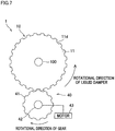
- FIG. 7 is a top view showing a liquid damper system of Third Embodiment.
- a gear mechanism 40 is provided as a relative rotation unit by which the liquid damper 10 is rotated relative to the rotating body 100.
- This gear mechanism 40 includes gear portions 11d formed on the outer circumferential surface of the liquid damper 10 (casing 11), a gear 41 engaged with the gear portions 11d, a rotational shaft 42 connected to the gear 41 and substantially in parallel to the rotating body 100, and a motor 43 (driving unit) having an unillustrated output shaft connected to the rotational shaft 42 and configured to rotationally drive the rotational shaft 42.
- a housing (not illustrated) of the motor 43 is, for example, attached to the rotating body 100 via a bearing which is substantially without friction, and the housing is provided so that the position of the motor 43 is not varied when the rotating body 100 and/or the liquid damper 10 rotates.
- liquid damper 10 is arranged to rotate relative to the rotating body 100.
- the motor 43 is preferably a variable speed motor in which the rotation speed of the output shaft is variable.
- the rotation speed of the gear 41 is therefore adjustable, and hence the rotation speed of the liquid damper 10 is variable.
- the rotation speed of the liquid damper 10 is adjustable in accordance with the state of vibration of the rotating body 100, and hence the degree of vibration suppression is further improved.
- the collision members 14 protrude from the inner wall surface 11c which is on the outer side in the centrifugal direction of the casing 11 toward the internal space 12.
- the collision members 14 may protrude toward the internal space 12 from the inner wall surface on the inner side in the centrifugal direction of the casing 11, or may protrude toward the internal space 12 from the ceiling or the bottom surface of the casing 11.
- each collision member 14 may be a plate-shaped member which is provided to bridge the gap between the inner wall surface on the inner side in the centrifugal direction and the inner wall surface on the outer side in the centrifugal direction and has an opening or a notch which penetrates the plate-shaped member in the circumferential direction.
- each collision member 14 may not be plate-shaped and may be column-shaped or block-shaped. Furthermore, each collision member 14 may be an uneven portion or a corrugated portion formed on a side or bottom surface of the casing 11.
- the internal space 12 of the casing 11 is a single chamber.
- a partition wall may be provided in the internal space 12 along the circumferential direction to divide the internal space 12 into plural spaces in the radial direction.
- a collision member 14 is provided in each of these spaces formed by the division.
- the plate members 21 to 23 are provided on the outer circumferential surface of the liquid damper 10 (casing 11), the plate members 21 to 23 may be formed on an end face (an upper surface or a lower surface) in the axial direction of the liquid damper 10 (casing 11), in addition to or instead of the outer circumferential surface.
- plate members 25 are provided on an upper surface 11e of a liquid damper 10 (casing 11).
- plate members 25 may be provided on a lower surface.
- This arrangement restrains increase in size of the liquid damper system 1 in the radial direction, and the liquid damper system 1 is downsized.
- the conductor 31 is provided in the liquid damper 10 as an electromagnetic effect target and the coil 32 is provided around the liquid damper 10 as an electromagnetic effector.
- a coil may be provided in the liquid damper 10 as an electromagnetic effect target whereas a permanent magnet may be provided around the liquid damper 10 as an electromagnetic effector.
- the rotation speed of the liquid damper 10 is adjustable by changing the distance to the liquid damper 10 by moving the permanent magnet.
- the direction of the fluid blowing unit 24 in Modification 2 of First Embodiment may be changed to exert a hydrostatic pressure in the rotational direction of the liquid damper 10.
- the rotation speed of the liquid damper 10 may be arranged to be higher than that of the rotating body 100, by means of the motor 43.
- the rotational direction of the liquid damper 10 may be arranged to be opposite to the rotational direction of the rotating body 100.
- the liquid damper 10 may be rotated in the direction opposite to the rotation of the rotating body 100 by increasing the speed of fluid blown out from the fluid blowing unit 24 in Modification 2 of First Embodiment (see FIG. 5 ).
- the liquid damper 10 may be arranged to rotate in the direction opposite to that of the rotating body 100, by means of the motor 42.
Landscapes
- Engineering & Computer Science (AREA)
- General Engineering & Computer Science (AREA)
- Mechanical Engineering (AREA)
- Physics & Mathematics (AREA)
- Acoustics & Sound (AREA)
- Aviation & Aerospace Engineering (AREA)
- Power Engineering (AREA)
- Textile Engineering (AREA)
- Electromagnetism (AREA)
- Fluid-Damping Devices (AREA)
- Vibration Prevention Devices (AREA)
- Main Body Construction Of Washing Machines And Laundry Dryers (AREA)
Applications Claiming Priority (2)
| Application Number | Priority Date | Filing Date | Title |
|---|---|---|---|
| JP2015199097 | 2015-10-07 | ||
| PCT/JP2016/068859 WO2017061147A1 (ja) | 2015-10-07 | 2016-06-24 | 液体ダンパーシステム |
Publications (2)
| Publication Number | Publication Date |
|---|---|
| EP3361120A1 true EP3361120A1 (de) | 2018-08-15 |
| EP3361120A4 EP3361120A4 (de) | 2019-06-26 |
Family
ID=58487429
Family Applications (1)
| Application Number | Title | Priority Date | Filing Date |
|---|---|---|---|
| EP16853302.4A Pending EP3361120A4 (de) | 2015-10-07 | 2016-06-24 | Flüssigkeitsdämpfersystem |
Country Status (7)
| Country | Link |
|---|---|
| US (1) | US10883564B2 (de) |
| EP (1) | EP3361120A4 (de) |
| JP (1) | JP6539745B2 (de) |
| KR (1) | KR102027267B1 (de) |
| CN (1) | CN108138887B (de) |
| TW (1) | TWI700446B (de) |
| WO (1) | WO2017061147A1 (de) |
Families Citing this family (5)
| Publication number | Priority date | Publication date | Assignee | Title |
|---|---|---|---|---|
| CN110382909B (zh) * | 2017-03-31 | 2021-05-25 | 日本Tmt机械株式会社 | 减振装置以及筒管支架系统 |
| JP6770019B2 (ja) * | 2018-05-10 | 2020-10-14 | ファナック株式会社 | 複数のモータが1つの動作軸を駆動する駆動装置、及び駆動装置を備えるロボット |
| CN109505908A (zh) * | 2018-12-28 | 2019-03-22 | 江阴凯迈机械有限公司 | 销杆粘滞滑动轴承式阻尼器 |
| CN113833777B (zh) * | 2021-11-25 | 2022-03-22 | 东营昱辰技术有限公司 | 一种油田用具有缓冲功能的梁式抽油机辅助刹车装置 |
| CN114623199A (zh) * | 2022-03-31 | 2022-06-14 | 安徽江淮汽车集团股份有限公司 | 扭转减振器 |
Family Cites Families (15)
| Publication number | Priority date | Publication date | Assignee | Title |
|---|---|---|---|---|
| JPH0381437U (de) | 1989-12-12 | 1991-08-20 | ||
| GB9801780D0 (en) * | 1998-01-29 | 1998-03-25 | Rover Group | A roll damper arrangement |
| KR100640866B1 (ko) | 2004-09-08 | 2006-11-02 | 엘지전자 주식회사 | 세탁기의 밸런서 |
| JP4417816B2 (ja) | 2004-10-14 | 2010-02-17 | アトムリビンテック株式会社 | ロータリダンパ回転制御装置 |
| JP4254696B2 (ja) | 2004-11-22 | 2009-04-15 | ソニー株式会社 | 自動平衡装置、回転駆動装置及びディスク駆動装置 |
| ITTO20070412A1 (it) | 2007-06-11 | 2008-12-12 | Antonino Cultraro | Smorzatore rotativo con innesto unidirezionale. |
| CN201265619Y (zh) | 2008-09-27 | 2009-07-01 | 翟羽倬 | 一种单向旋转缓冲器 |
| JP5469102B2 (ja) | 2011-01-07 | 2014-04-09 | シャープ株式会社 | 洗濯機 |
| CN102927188A (zh) | 2011-08-12 | 2013-02-13 | 北京中金社文化有限公司 | 一种阻尼机构 |
| JP5922446B2 (ja) | 2012-03-08 | 2016-05-24 | 株式会社ニフコ | 回転ダンパ |
| US9362812B2 (en) * | 2012-09-18 | 2016-06-07 | Honeywell International Inc. | Shaft coupling apparatus, rotary fluid damper, and deployable device with magnetic coupling mechanism |
| JP5925672B2 (ja) | 2012-12-27 | 2016-05-25 | 株式会社構造計画研究所 | 減衰装置、及び構造物の制振装置 |
| JP6031351B2 (ja) * | 2012-12-27 | 2016-11-24 | 株式会社東海理化電機製作所 | 車両用ミラー装置 |
| US20150159722A1 (en) * | 2013-12-05 | 2015-06-11 | GM Global Technology Operations LLC | Torsional keyed sleeve fluid damper |
| DK3169454T3 (en) * | 2014-07-14 | 2018-06-18 | Stoneage Inc | ISOLATED RENTAL VISCOS SPEED INHIBITOR FOR ROTATING NOZZLE |
-
2016
- 2016-06-24 KR KR1020187009526A patent/KR102027267B1/ko active IP Right Grant
- 2016-06-24 US US15/766,217 patent/US10883564B2/en active Active
- 2016-06-24 WO PCT/JP2016/068859 patent/WO2017061147A1/ja active Application Filing
- 2016-06-24 EP EP16853302.4A patent/EP3361120A4/de active Pending
- 2016-06-24 JP JP2017544386A patent/JP6539745B2/ja active Active
- 2016-06-24 CN CN201680055547.9A patent/CN108138887B/zh active Active
- 2016-10-06 TW TW105132430A patent/TWI700446B/zh active
Also Published As
| Publication number | Publication date |
|---|---|
| CN108138887B (zh) | 2019-11-22 |
| KR20180049027A (ko) | 2018-05-10 |
| US20180298981A1 (en) | 2018-10-18 |
| EP3361120A4 (de) | 2019-06-26 |
| CN108138887A (zh) | 2018-06-08 |
| JPWO2017061147A1 (ja) | 2018-07-26 |
| US10883564B2 (en) | 2021-01-05 |
| TW201713872A (zh) | 2017-04-16 |
| KR102027267B1 (ko) | 2019-10-01 |
| JP6539745B2 (ja) | 2019-07-03 |
| WO2017061147A1 (ja) | 2017-04-13 |
| TWI700446B (zh) | 2020-08-01 |
Similar Documents
| Publication | Publication Date | Title |
|---|---|---|
| US10883564B2 (en) | Liquid damper system | |
| JP6818506B2 (ja) | 高速において回転機械のロータのバランスを取るためのバランス方法 | |
| US11686369B2 (en) | Vibration damping device and bobbin holder system | |
| US20060275155A1 (en) | Rotational apparatus | |
| JP6089020B2 (ja) | ローターのバランスを取るための方法およびポンプ | |
| EP3333301A1 (de) | Kleiderbehandlungsvorrichtung | |
| JP2015113981A (ja) | 回転システム | |
| WO2021015018A1 (ja) | 真空ポンプ、及び、真空ポンプに用いられるロータ並びに回転翼 | |
| US11209069B1 (en) | Dynamic balancing apparatus | |
| EP3243948B1 (de) | Waschmaschine und unwuchtausgleichsvorrichtung für waschmaschine | |
| JP7177113B2 (ja) | フランジ要素 | |
| JP2022023779A (ja) | 電気モータ又は電気モータを備える真空機器を製造する方法 | |
| JP2008045747A (ja) | 流体機械のロータ | |
| JPH0942376A (ja) | ターンホイール | |
| WO2016207080A1 (en) | Washing machine and balance ring for washing machine | |
| EP4299913A1 (de) | Zentrifugalverdichter für kühlsystem und kühlsystem | |
| JP2002285988A (ja) | 分子ポンプ | |
| PL226195B1 (pl) | Urzadzenie do redukcji drgan w rezonansie przejsciowym wirnika z eliminatorem synchronicznym | |
| KR20040087093A (ko) | 도너츠 형태의 폐쇄계 내부에서 발생하는 가로힘에 의한폐쇄계의 내부 추진방법 및 그 폐쇄계의 내부 추진장치 |
Legal Events
| Date | Code | Title | Description |
|---|---|---|---|
| STAA | Information on the status of an ep patent application or granted ep patent |
Free format text: STATUS: THE INTERNATIONAL PUBLICATION HAS BEEN MADE |
|
| PUAI | Public reference made under article 153(3) epc to a published international application that has entered the european phase |
Free format text: ORIGINAL CODE: 0009012 |
|
| STAA | Information on the status of an ep patent application or granted ep patent |
Free format text: STATUS: REQUEST FOR EXAMINATION WAS MADE |
|
| 17P | Request for examination filed |
Effective date: 20180420 |
|
| AK | Designated contracting states |
Kind code of ref document: A1 Designated state(s): AL AT BE BG CH CY CZ DE DK EE ES FI FR GB GR HR HU IE IS IT LI LT LU LV MC MK MT NL NO PL PT RO RS SE SI SK SM TR |
|
| AX | Request for extension of the european patent |
Extension state: BA ME |
|
| DAV | Request for validation of the european patent (deleted) | ||
| DAX | Request for extension of the european patent (deleted) | ||
| A4 | Supplementary search report drawn up and despatched |
Effective date: 20190527 |
|
| RIC1 | Information provided on ipc code assigned before grant |
Ipc: F16F 15/16 20060101ALI20190521BHEP Ipc: F16F 9/12 20060101AFI20190521BHEP |
|
| STAA | Information on the status of an ep patent application or granted ep patent |
Free format text: STATUS: EXAMINATION IS IN PROGRESS |
|
| 17Q | First examination report despatched |
Effective date: 20200311 |
|
| STAA | Information on the status of an ep patent application or granted ep patent |
Free format text: STATUS: EXAMINATION IS IN PROGRESS |
|
| STAA | Information on the status of an ep patent application or granted ep patent |
Free format text: STATUS: EXAMINATION IS IN PROGRESS |
|
| P01 | Opt-out of the competence of the unified patent court (upc) registered |
Effective date: 20230426 |
|
| RIC1 | Information provided on ipc code assigned before grant |
Ipc: D06F 37/22 20060101ALN20240124BHEP Ipc: D06F 37/24 20060101ALI20240124BHEP Ipc: H02K 49/10 20060101ALI20240124BHEP Ipc: F16D 63/00 20060101ALI20240124BHEP Ipc: F16F 15/16 20060101ALI20240124BHEP Ipc: F16F 9/12 20060101AFI20240124BHEP |
|
| GRAP | Despatch of communication of intention to grant a patent |
Free format text: ORIGINAL CODE: EPIDOSNIGR1 |
|
| STAA | Information on the status of an ep patent application or granted ep patent |
Free format text: STATUS: GRANT OF PATENT IS INTENDED |
|
| INTG | Intention to grant announced |
Effective date: 20240409 |