EP3360726A1 - Seatback structure having pivotable upper seatback support - Google Patents
Seatback structure having pivotable upper seatback support Download PDFInfo
- Publication number
- EP3360726A1 EP3360726A1 EP18155359.5A EP18155359A EP3360726A1 EP 3360726 A1 EP3360726 A1 EP 3360726A1 EP 18155359 A EP18155359 A EP 18155359A EP 3360726 A1 EP3360726 A1 EP 3360726A1
- Authority
- EP
- European Patent Office
- Prior art keywords
- side frame
- end portion
- seatback
- lower side
- link
- Prior art date
- Legal status (The legal status is an assumption and is not a legal conclusion. Google has not performed a legal analysis and makes no representation as to the accuracy of the status listed.)
- Withdrawn
Links
- 238000005452 bending Methods 0.000 claims description 4
- 230000007246 mechanism Effects 0.000 description 19
- 239000002184 metal Substances 0.000 description 6
- 230000002452 interceptive effect Effects 0.000 description 5
- 230000033001 locomotion Effects 0.000 description 5
- 230000003014 reinforcing effect Effects 0.000 description 3
- 238000003466 welding Methods 0.000 description 3
- 229910000831 Steel Inorganic materials 0.000 description 2
- 230000005540 biological transmission Effects 0.000 description 2
- 239000010959 steel Substances 0.000 description 2
- 229920005830 Polyurethane Foam Polymers 0.000 description 1
- 230000004075 alteration Effects 0.000 description 1
- 238000006243 chemical reaction Methods 0.000 description 1
- 239000004744 fabric Substances 0.000 description 1
- 230000002349 favourable effect Effects 0.000 description 1
- 239000010985 leather Substances 0.000 description 1
- 239000002649 leather substitute Substances 0.000 description 1
- 239000000463 material Substances 0.000 description 1
- 238000012986 modification Methods 0.000 description 1
- 230000004048 modification Effects 0.000 description 1
- 239000011496 polyurethane foam Substances 0.000 description 1
- 229920003002 synthetic resin Polymers 0.000 description 1
- 239000000057 synthetic resin Substances 0.000 description 1
Images



Classifications
-
- B—PERFORMING OPERATIONS; TRANSPORTING
- B60—VEHICLES IN GENERAL
- B60N—SEATS SPECIALLY ADAPTED FOR VEHICLES; VEHICLE PASSENGER ACCOMMODATION NOT OTHERWISE PROVIDED FOR
- B60N2/00—Seats specially adapted for vehicles; Arrangement or mounting of seats in vehicles
- B60N2/02—Seats specially adapted for vehicles; Arrangement or mounting of seats in vehicles the seat or part thereof being movable, e.g. adjustable
- B60N2/22—Seats specially adapted for vehicles; Arrangement or mounting of seats in vehicles the seat or part thereof being movable, e.g. adjustable the back-rest being adjustable
- B60N2/2222—Seats specially adapted for vehicles; Arrangement or mounting of seats in vehicles the seat or part thereof being movable, e.g. adjustable the back-rest being adjustable the back-rest having two or more parts
-
- B—PERFORMING OPERATIONS; TRANSPORTING
- B60—VEHICLES IN GENERAL
- B60N—SEATS SPECIALLY ADAPTED FOR VEHICLES; VEHICLE PASSENGER ACCOMMODATION NOT OTHERWISE PROVIDED FOR
- B60N2/00—Seats specially adapted for vehicles; Arrangement or mounting of seats in vehicles
- B60N2/02—Seats specially adapted for vehicles; Arrangement or mounting of seats in vehicles the seat or part thereof being movable, e.g. adjustable
- B60N2/22—Seats specially adapted for vehicles; Arrangement or mounting of seats in vehicles the seat or part thereof being movable, e.g. adjustable the back-rest being adjustable
-
- B—PERFORMING OPERATIONS; TRANSPORTING
- B60—VEHICLES IN GENERAL
- B60N—SEATS SPECIALLY ADAPTED FOR VEHICLES; VEHICLE PASSENGER ACCOMMODATION NOT OTHERWISE PROVIDED FOR
- B60N2/00—Seats specially adapted for vehicles; Arrangement or mounting of seats in vehicles
- B60N2/64—Back-rests or cushions
-
- B—PERFORMING OPERATIONS; TRANSPORTING
- B60—VEHICLES IN GENERAL
- B60N—SEATS SPECIALLY ADAPTED FOR VEHICLES; VEHICLE PASSENGER ACCOMMODATION NOT OTHERWISE PROVIDED FOR
- B60N2/00—Seats specially adapted for vehicles; Arrangement or mounting of seats in vehicles
- B60N2/68—Seat frames
-
- B—PERFORMING OPERATIONS; TRANSPORTING
- B60—VEHICLES IN GENERAL
- B60N—SEATS SPECIALLY ADAPTED FOR VEHICLES; VEHICLE PASSENGER ACCOMMODATION NOT OTHERWISE PROVIDED FOR
- B60N2/00—Seats specially adapted for vehicles; Arrangement or mounting of seats in vehicles
- B60N2/68—Seat frames
- B60N2/682—Joining means
-
- B—PERFORMING OPERATIONS; TRANSPORTING
- B60—VEHICLES IN GENERAL
- B60N—SEATS SPECIALLY ADAPTED FOR VEHICLES; VEHICLE PASSENGER ACCOMMODATION NOT OTHERWISE PROVIDED FOR
- B60N2205/00—General mechanical or structural details
- B60N2205/30—Seat or seat parts characterised by comprising plural parts or pieces
Definitions
- the present invention relates to a seatback structure for a vehicle seat provided with a pivotable upper seatback support.
- a seatback structure for a vehicle seat provided with a pivotable upper seatback support is known. See JP2010-42748A and JP2013-23065A , for instance.
- the seatback includes a seatback lower support having a lower end attached to a rear end part of a seat cushion (typically via a reclining mechanism), and a seatback upper support having a lower end pivotally attached to an upper end of the seatback lower support.
- a drive mechanism is incorporated in the seatback for actuating the seatback upper support relative to the seatback lower support.
- a motor mount plate extends between a pair of side members of the lower seatback support to support an electric motor, and a nut and screw mechanism is provided in association with a pivot mechanism provided between the upper seatback support and the lower seatback support.
- a wire and pulley mechanism transmits the power of the electric motor to the nut and screw mechanism.
- JP2013-23065A discloses a similar seatback structure.
- the power of an electric motor provided in the lower seatback support is transmitted to a nut and screw mechanism for tilting the upper seatback support relative to the lower seatback support via a torsional flexible cable.
- a conventional seatback structure includes various component parts over a large area of the seatback, some care is required to avoid interference between moveable component parts of the drive mechanism with the pad of the seatback. Also, the drive mechanism including a transmission mechanism occupies a relative large space, and this complicates the seatback design.
- An object of at least the preferred embodiments of the present invention is to provide a seatback structure for a vehicle seat provided with a pivotable upper seatback support which can effectively prevent component parts for tilting the upper seatback support relative to the lower seatback support from interfering with surrounding members.
- a second object of at least the preferred embodiments of the present invention is to provide such a seatback structure provided with an actuator including a transmission mechanism which is compact in size.
- the present invention provides a seatback structure for a vehicle seat, comprising: a pair of lower side frames extending vertically; a pair of upper side frames having lower end portions pivotally connected to upper end portions of the respective lower side frames around a laterally extending rotational center line; an upper frame fixedly connected between upper ends of the upper side frames; at least one actuator fixedly secured to one of the lower side frames and including an output end configured to move linearly along a length of the lower side frame; and a link having an upper end pivotally connected to a part of the corresponding upper side frame and a lower end pivotally connected to the output end of the actuator; wherein the upper end portion of the one lower side frame and the lower end portion of the corresponding upper side frame comprise plate members facing laterally each other in an overlying relationship, and at least partly interposing the link therebetween.
- the link is thus at least partly covered by the upper side frame and the lower side frame so that the link is protected from interfering with a surrounding member. Thereby, an unobstructed movement of the link is ensured.
- an upper end portion of the link is interposed between the upper end portion of the lower side frame and the lower end portion of the upper side frame.
- the link is protected from interfering with a surrounding member. Thereby, an unobstructed movement of the link is ensured.
- an edge of the upper end portion of the lower side frame is bent away from the lower end portion of the upper side frame to form a lower flange, the lower flange extending from a part in front of and below the rotational center line to a part behind and below the rotational center line past a part above the rotational center line.
- a front edge and a rear edge of the lower end portion of the upper side frame are bent toward the upper end portion of the lower side frame to define a pair of upper flanges, each upper flange extending from a part below the rotational center line to a part above the rotational center line.
- the lower flange and the upper flanges extend in a laterally inward direction.
- the lateral dimension of the side frame consisting of the upper side frame and the lower side frame can be minimized.
- a front edge and a rear edge of the lower end portion of the upper side frame are bent away from the upper end portion of the lower side frame to define a pair of upper flanges, each upper flange extending from a part below the rotational center line to a part above the rotational center line.
- an upper flange lower part formed by bending a lower edge of the upper side frame away from the upper end portion of the lower side frame extends between the lower edges of the upper flanges.
- a part of the upper end portion of the lower side frame facing the lower end portion of the upper side frame is formed with a recess that at least partly receives the link.
- the protrusion of the link from the outer profile of the lower side frame can be minimized or totally avoided, and the link is prevented from interfering with a surrounding member in a favorable manner.
- a lower end part of the recess is formed with a vertically elongated through hole receiving a pin attached to a lower end part of the link, and the actuator is attached to a side of the lower side frame facing away from the link, another end of the pin being attached to the output end.
- the actuator can be positioned between the opposing sections of the lower flange of the lower side frame so that the actuator and the link can be positioned without unduly protruding from the outer profile of the lower side frame.
- the seatback structure of the present invention can be favorably applied to a seatback provided with a lower seatback support and an upper seatback support pivotably connected to the upper end of the lower seatback support.
- This seatback is provided with a lower seatback support and an upper seatback support pivotably connected to the upper end of the lower seatback support.
- a seat S for a vehicle includes a seat cushion S1 defining a seat surface, a seatback S2 defining a back rest surface, a headrest S3, and a slide rail system S4.
- the slide rail system S4 includes a pair of slide rails extending in the fore and aft direction on the floor of the vehicle, and supports the seat cushion S1 so as to be slidable in the fore and aft direction.
- the seatback S2 is connected to the seat cushion S1 via a reclining mechanism 1 so as to be rotatable (tiltable), and the headrest S3 is provided on the upper end of the seatback S2 so as to be vertically slidable.
- the seat cushion S1 is formed by covering a seat cushion frame with a pad and a skin member.
- the front side and the lateral sides of the seatback S2 are formed by covering a seatback frame F (see Figure 3 ) with a pad and a skin member SK, and the rear portion of the seatback S2 is formed by attaching a backboard B to the seatback frame F.
- the headrest S3 is formed by covering a head rest frame with a pad and a skin member.
- the pad may consist of resilient cushion material such as polyurethane foam, and the skin member SK may be formed of leather, synthetic leather, cloth or the like, and the backboard B may be made of synthetic resin or the like.
- the seatback S2 includes a lower seatback support S2A connected to the seat cushion S1 via the reclining mechanism 1, and an upper seatback support S2B connected to the upper end of the lower seatback support S2A so as to be rotatable (tiltable) with respect to the lower seatback support S2A.
- the headrest S3 is provided on the upper end of the upper seatback support S2B.
- the backboard B includes a backboard lower part BA attached to the rear side of the lower seatback support S2A and a backboard upper part BB attached to the rear side of the upper seatback support S2B.
- the seat cushion frame includes a pair of left and right cushion side frames extending in the fore and aft direction on either side of the seat cushion frame, a front frame extending between the front ends of the cushion side frames, and a rear frame extending between the rear ends of the cushion side frames, so as to form a substantially rectangular frame structure.
- the slide rail system S4 is attached to the cushion side frames.
- the seatback frame F includes a pair of right and left side frames 2 extending substantially vertically on either side of the seatback frame F, a lower frame 4 extending laterally between lower portions of the side frames 2, and an inverted U-shaped upper frame 5 joined to the upper portions of the side frames 2 at respective ends thereof, so as to form a substantially rectangular frame structure.
- Each side frame 2 is formed by three sheet metal members (plate members) arranged one above another in the vertical direction.
- the lower two sheet metal members are joined to each other by welding or the like to jointly form a lower side frame 6.
- the uppermost sheet metal member forms an upper side frame 7 which is connected to the upper end of the corresponding the lower side frame 6 so as to be rotatable around a rotational center line X extending in the lateral direction.
- the lower end of each lower side frame 6 is joined to the corresponding lower frame 4 by welding, for example, and the upper frame 5 is joined to the upper side frame 7 by welding, for example.
- the lower frame 4 and the lower side frames 6 jointly form a seatback frame lower part FA, and the upper side frames 7 and the upper frame 5 jointly form a seatback frame upper part FB.
- the lower side frame 6 has a substantially smaller lateral dimension than the fore and aft dimension thereof, and thus has a major plane facing in the lateral direction.
- the lower side frame 6 narrows toward the upper end portion 6A thereof which is formed in a substantially semicircular shape when viewed from the lateral side.
- the front edge, the upper edge, and the rear edge of the lower side frame 6 are bent inward (with respect to the seat S) so as to form a lower side flange 6C.
- the lower side flange 6C thus includes a lower flange front part 6D extending along the front edge of the lower side frame 6, a lower flange upper part 6E extending along the edge of the upper end part of the lower side frame 6, and a lower flange rear part 6F extending along the rear edge of the lower side frame 6.
- the lower flange front part 6D and the lower flange upper part 6E are connected to each other by a front connecting wall 6G, and the lower flange rear part 6F and the lower flange upper part 6E are connected to each other by a rear connecting wall 6H.
- the lower flange front part 6D, the front connecting wall 6G, the lower flange upper part 6E, the rear connecting wall 6H, and the lower flange rear part 6F jointly form a continuous flange or a continuous wall.
- the lower flange upper part 6E extends substantially in a semicircular shape.
- the surfaces of the front connecting wall 6G and the rear connecting wall 6H face substantially vertically.
- a recess 6J which is recessed in the inward direction is formed on the outer side of an upper end part of the lower side frame 6.
- the recess 6J is elongated in the longitudinal (vertical) direction of the lower side frame 6, and extends to the upper edge of the upper end portion 6A of the lower side frame 6.
- a lower end part of the recess 6J is formed with a through hole 6K that is passed through the lower side frame 6.
- the through hole 6K is formed as a vertically elongated hole.
- the upper side frame 7 has a major plane facing laterally, and extends vertically.
- the lower end portion 7A of the upper side frame 7 is overlaid on the upper end portion 6A of the lower side frame 6 from the outer side.
- the upper side frame 7 is provided with an upper flange front part 7B and an upper flange rear part 7C along the front edge and the rear edge of thereof, respectively, by bending the respective edge parts of the upper side frame 7 in the inward direction.
- the upper flange front part 7B is disposed in front of the lower flange upper part 6E
- the upper flange rear part 7C is disposed behind the lower flange upper part 6E.
- the lower flange upper part 6E is disposed between the upper flange front part 7B and the upper flange rear part 7C in the fore and aft direction.
- the lower edge of the upper flange front part 7B faces the front connecting wall 6G with a gap defined therebetween, and the lower edge of the upper flange rear part 7C faces the rear connecting wall 6H with a gap defined therebetween.
- the lower end portion 7A of the upper side frame 7 is rotatably coupled to the upper end portion 6A of the lower side frame 6 via a shaft member 22 extending laterally.
- the center of the shaft member 22 is the rotational center line X between the upper side frame 7 and the lower side frame 6.
- the lower flange upper part 6E partly surrounds the shaft member 22, and extends in the inward direction beyond the shaft member 22. More specifically, the lower flange upper part 6E extends from a point in front of and below the shaft member 22, passes above the shaft member 22, and extends to a point behind and below the shaft member 22.
- the lower side flange 6C extends from the lower side frame 6 away from the side of the upper side frame 7, and the upper flange front part 7B extends from the upper side frame 7 toward the side of the lower side frame 6.
- the upper flange front part 7B extends vertically downward in front of the shaft member 22 to a point below the shaft member 22, and the upper flange rear part 7C extends vertically downward behind the shaft member 22 to a point below the shaft member 22.
- the lower end portion 7A of the upper side frame 7 is disposed at a position overlapping with an upper end part of the recess 6J.
- a first board mounting portion 8 consisting of a U-shaped steel bar is fixed to a vertically intermediate part of each lower side frame 6 at the two legs thereof so as to project inward from the corresponding lower flange rear part 6F.
- a lateral extension 10 in the form of a metal strip extends inward from an upper end part of each lower flange rear part 6F, and a second board mounting portion 9 consisting of a U-shaped steel bar is fixed to the free end of the lateral extension 10 at the two legs thereof.
- the first board mounting portions 8 and the second board mounting portions 9 are used for attaching the backboard lower part BA to the seatback frame lower part FA.
- a third board mounting portion 11 in the form of a metal strip extends inward from an intermediate part of each upper flange rear part 7C.
- the third board mounting portions 11 are used for attaching the backboard upper part BB to the seatback frame upper part FB.
- a pair of headrest holding pipes 12 for supporting the headrest S3 are joined to a central part of the upper frame 5 in a mutually spaced apart relationship.
- a reinforcing frame 13 consisting of a plate member extends between a pair of pillar portions of the upper frame 5 extending in the generally vertical direction. The two ends of the reinforcing frame 13 are partly wrapped around the respective pillar portions of the upper frame 5 and are spot welded or otherwise fixedly attached thereto.
- the reinforcing frame 13 is formed with a pair of through holes 13a for securing the backboard upper part BB to the upper frame 5.
- a power actuator 17 for tilting the right upper side frame 7 via a link mechanism 16 is attached to the inner surface of the right lower side frame 6.
- the actuator 17 includes an electric motor 18, a speed reduction mechanism connected to the output shaft of the electric motor 18, and a conversion mechanism such as a feed screw or a ball screw for converting the rotational motion of the speed reduction mechanism into a rectilinear motion of an output end 17a thereof.
- Various other per se known mechanisms can also be applied.
- the actuator 17 is fixed to the inner surface of the lower side frame 6 with threaded bolts or the like in such a manner that the output end 17a moves along the length of the lower side frame 6.
- An air bag unit 19 for protecting the occupant's side at the time of a vehicle crash is attached to a lower part of the inner side of the left lower side frame 6.
- Figure 4 shows the inner surface of the right side frame 2
- Figure 5 shows the outer surface of the right side frame 2, in a rearward inclined position where the upper side frame 7 aligns with the lower side frame 6 along a straight line in side view.
- the recess 6J receives a link 25 consisting of a sheet metal member and extending in the longitudinal direction of the recess 6J substantially in parallel to the lower side frame 6.
- the lower end of the link 25 is provided with a first pin 24 which is passed through the through hole 6K, and connected to the output end 17a.
- the upper end of the link 25 is disposed between the lower side frame 6 and the upper side frame 7, and is pivotally coupled to the upper side frame 7 via a second pin 27.
- the second pin 27 is positioned behind and below the shaft member 22.
- FIG. 6a shows the upper side frame 7 in the rearward tilted position which is defined by the abutting of the first pin 24 onto the lower edge of the through hole 6K
- Figure 6b shows the upper side frame 7 in a most forward tilted position which is defined by the abutting of the first pin 24 onto the upper edge of the through hole 6K.
- the first pin 24 moves upward in the through hole 6K along the lower side frame 6. This causes the link 25 to push upward the second pin 27 located behind the rotational center line X of the upper side frame 7 so that the upper side frame 7 tilts forward.
- the actuator 17 fixedly attached to the lower side frame 6 is provided with the output end 17a that is configured to move linearly along the lower side frame 6.
- the actuator 17 tilts the seatback frame upper part FB in the forward or rearward direction via the link mechanism 16 including the link 25 connected between a part of the upper side frame 7 located behind the rotational center line X via the second pin 27 and the output end 17a of the actuator 17 via the first pin 24. Therefore, the seatback S2 can be provided with a relatively small thickness (fore and aft dimension), and the actuator 17 can be attached to the lower side frame 6 in a stable manner with a minimum number of component parts.
- the upper end part of the link 25 is covered between the upper end portion 6A of the lower side frame 6 and the lower end portion 7A of the upper side frame 7 so that the link 25 is prevented from touching the surrounding objects. Furthermore, because the link 25 is received in the recess 6J, and prevented from protruding from the lower side frame 6 (or at least the protrusion of the link 25 from the outer profile of the lower side frame 6 is minimized), the link 25 is favorably prevented from interfering with the surrounding objects.
- the upper end portion 6A of the lower side frame 6 is provided with the lower side flange 6C (the lower flange upper part 6E) in a continuous manner so that the stiffness of the lower side frame 6 is improved.
- the lower end portion 7A of the upper side frame 7 is provided with the upper flange front part 7B and the upper flange rear part 7C along the front edge and the rear edge of thereof, respectively, so that the stiffness of the upper side frame 7 is improved. Because of the presence of the lower flange upper part 6E between the upper flange front part 7B and the upper flange rear part 7C, the stiffness of the junction between the lower side frame 6 and the upper side frame 7 is improved.
- the lower side frame 6 is provided with the through hole 6K elongated in the lengthwise direction of the lower side frame 6 to guide the output end 17a of the actuator 17 via the first pin 24 so that a play in the output end 17a of the actuator 17 is minimized, and the tilting of the upper seatback support S2B can be performed in a smooth manner.
- the output end 17a of the actuator 17 is connected to the link 25 via the first pin 24 passed laterally through the through hole 6K so that the through hole 6K guides the output end 17a via the first pin 24. Therefore, the number of component parts for this guide structure can be minimized.
- the output end 17a of the actuator 17 is positioned in front of the lateral extension 10 so that the output end 17a of the actuator 17 is covered by the lateral extension 10 from behind. Therefore, the output end 17a is prevented from being interfered by a surrounding member of the seatback S2.
- the actuator 17 for tiling the upper seatback support S2B is positioned on the inner side of one of the lower side frames 6 so that the available space can be efficiently utilized for accommodating the actuator 17 including the motor 15 and the thickness (fore and aft direction) of the seatback S2 is not required to be increased.
- the air bag unit 19 is positioned on the inner side of the other lower side frame 6 so that the available space can be efficiently utilized for accommodating the air bag unit 19, and the thickness (fore and aft direction) of the seatback S2 is not required to be increased.
- the seatback structure of the present invention is applicable not only to motor vehicles but also to railway trains, aircraft and watercraft.
- the seatback structure of the present invention may also be applied to chairs and sofas for offices and homes.
- the configurations of the lower side flange 6C, the upper flange front part 7B and the upper flange rear part 7C can be modified without departing from the spirit of the present invention.
- the upper flange front part 7B' and the upper flange rear part 7C' may be directed outward (away from the lower side frame 6).
- the lower ends of the upper flange front part 7B' and the upper flange rear part 7C' may be connected to each other by an upper flange lower part 7D' formed by bending the lower edge of the upper side frame 7 in the outward direction (or away from the lower side frame 6) and extending under the rotational center line X, possible with small breaks.
- the upper flange lower part (7D') extends between the lower edges of the upper flange front part 7B' and the upper flange rear part 7C'.
Landscapes
- Engineering & Computer Science (AREA)
- Aviation & Aerospace Engineering (AREA)
- Transportation (AREA)
- Mechanical Engineering (AREA)
- Seats For Vehicles (AREA)
- Chair Legs, Seat Parts, And Backrests (AREA)
Abstract
Provided is a seatback structure for a seatback provided with a lower seatback support and an upper seatback support pivotably connected to the upper end of the lower seatback support. An actuator (17) is fixedly secured to one of a pair lower side frames (6) of a seatback frame (F), and an output end (17a) of the actuator is configured to move linearly along a length of the lower side frame, and a link (25) is provided with an upper end pivotally connected to a part of a corresponding upper side frame (7) and a lower end pivotally connected to the output end of the actuator. The upper end portion of the lower side frame and the lower end portion of the corresponding upper side frame comprise plate members facing laterally each other in an overlying relationship, and at least partly interposing the link therebetween.
Description
- The present invention relates to a seatback structure for a vehicle seat provided with a pivotable upper seatback support.
- A seatback structure for a vehicle seat provided with a pivotable upper seatback support is known. See
JP2010-42748A JP2013-23065A - In the seatback structure disclosed in
JP2010-42748A -
JP2013-23065A - As such a conventional seatback structure includes various component parts over a large area of the seatback, some care is required to avoid interference between moveable component parts of the drive mechanism with the pad of the seatback. Also, the drive mechanism including a transmission mechanism occupies a relative large space, and this complicates the seatback design.
- An object of at least the preferred embodiments of the present invention is to provide a seatback structure for a vehicle seat provided with a pivotable upper seatback support which can effectively prevent component parts for tilting the upper seatback support relative to the lower seatback support from interfering with surrounding members.
- A second object of at least the preferred embodiments of the present invention is to provide such a seatback structure provided with an actuator including a transmission mechanism which is compact in size.
- The present invention provides a seatback structure for a vehicle seat, comprising: a pair of lower side frames extending vertically; a pair of upper side frames having lower end portions pivotally connected to upper end portions of the respective lower side frames around a laterally extending rotational center line; an upper frame fixedly connected between upper ends of the upper side frames; at least one actuator fixedly secured to one of the lower side frames and including an output end configured to move linearly along a length of the lower side frame; and a link having an upper end pivotally connected to a part of the corresponding upper side frame and a lower end pivotally connected to the output end of the actuator; wherein the upper end portion of the one lower side frame and the lower end portion of the corresponding upper side frame comprise plate members facing laterally each other in an overlying relationship, and at least partly interposing the link therebetween.
- The link is thus at least partly covered by the upper side frame and the lower side frame so that the link is protected from interfering with a surrounding member. Thereby, an unobstructed movement of the link is ensured.
- Preferably, an upper end portion of the link is interposed between the upper end portion of the lower side frame and the lower end portion of the upper side frame.
- Because the upper end portion of the link is covered by the upper end portion of the lower side frame and the lower end portion of the upper side frame, the link is protected from interfering with a surrounding member. Thereby, an unobstructed movement of the link is ensured.
- According to a preferred embodiment of the present invention, an edge of the upper end portion of the lower side frame is bent away from the lower end portion of the upper side frame to form a lower flange, the lower flange extending from a part in front of and below the rotational center line to a part behind and below the rotational center line past a part above the rotational center line.
- Thereby, the stiffness of the upper end portion of the lower side frame is favorably enhanced.
- Preferably, a front edge and a rear edge of the lower end portion of the upper side frame are bent toward the upper end portion of the lower side frame to define a pair of upper flanges, each upper flange extending from a part below the rotational center line to a part above the rotational center line.
- Thereby, the stiffness of the lower end portion of the upper side frame is favorably enhanced.
- Preferably, the lower flange and the upper flanges extend in a laterally inward direction.
- As the lower flange and the upper flanges extend in the same direction, the lateral dimension of the side frame consisting of the upper side frame and the lower side frame can be minimized.
- According to another preferred embodiment of the present invention, a front edge and a rear edge of the lower end portion of the upper side frame are bent away from the upper end portion of the lower side frame to define a pair of upper flanges, each upper flange extending from a part below the rotational center line to a part above the rotational center line. Optionally, an upper flange lower part formed by bending a lower edge of the upper side frame away from the upper end portion of the lower side frame extends between the lower edges of the upper flanges.
- Thereby, the stiffness of the lower end portion of the upper side frame is favorably enhanced.
- Preferably, a part of the upper end portion of the lower side frame facing the lower end portion of the upper side frame is formed with a recess that at least partly receives the link.
- By thus accommodating the link at least partly in the recess, the protrusion of the link from the outer profile of the lower side frame can be minimized or totally avoided, and the link is prevented from interfering with a surrounding member in a favorable manner.
- Preferably, a lower end part of the recess is formed with a vertically elongated through hole receiving a pin attached to a lower end part of the link, and the actuator is attached to a side of the lower side frame facing away from the link, another end of the pin being attached to the output end.
- Thus, the actuator can be positioned between the opposing sections of the lower flange of the lower side frame so that the actuator and the link can be positioned without unduly protruding from the outer profile of the lower side frame.
- Thus, the seatback structure of the present invention can be favorably applied to a seatback provided with a lower seatback support and an upper seatback support pivotably connected to the upper end of the lower seatback support.
- Hereinafter, embodiments of the invention will be described by way of example only, and with reference to the drawings, in which:
-
Figure 1 is a front perspective view of a vehicle seat incorporated with a seatback structure according to an embodiment of the present invention; -
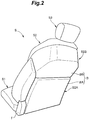
Figure 2 is a rear perspective view of the vehicle seat; -
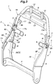
Figure 3 is a perspective view of a seatback frame; -
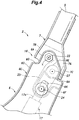
Figure 4 is a fragmentary side view of a part of the seatback frame as seen from outside; -
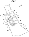
Figure 5 is a fragmentary side view of a part of the seatback frame as seen from inside; -
Figure 6a is a simplified side view of the seatback frame in a rearward tilted position; -
Figure 6b is a simplified side view of the seatback frame in a forward tilted position; and -
Figure 7 is a view similar toFigure 4 showing a modified embodiment of the present invention. - A seatback according to an embodiment of the present invention is described in the following with reference to the appended drawings. This seatback is provided with a lower seatback support and an upper seatback support pivotably connected to the upper end of the lower seatback support.
- As shown in
Figures 1 and2 , a seat S for a vehicle includes a seat cushion S1 defining a seat surface, a seatback S2 defining a back rest surface, a headrest S3, and a slide rail system S4. The slide rail system S4 includes a pair of slide rails extending in the fore and aft direction on the floor of the vehicle, and supports the seat cushion S1 so as to be slidable in the fore and aft direction. The seatback S2 is connected to the seat cushion S1 via a recliningmechanism 1 so as to be rotatable (tiltable), and the headrest S3 is provided on the upper end of the seatback S2 so as to be vertically slidable. - The seat cushion S1 is formed by covering a seat cushion frame with a pad and a skin member. The front side and the lateral sides of the seatback S2 are formed by covering a seatback frame F (see
Figure 3 ) with a pad and a skin member SK, and the rear portion of the seatback S2 is formed by attaching a backboard B to the seatback frame F. The headrest S3 is formed by covering a head rest frame with a pad and a skin member. The pad may consist of resilient cushion material such as polyurethane foam, and the skin member SK may be formed of leather, synthetic leather, cloth or the like, and the backboard B may be made of synthetic resin or the like. - The seatback S2 includes a lower seatback support S2A connected to the seat cushion S1 via the
reclining mechanism 1, and an upper seatback support S2B connected to the upper end of the lower seatback support S2A so as to be rotatable (tiltable) with respect to the lower seatback support S2A. The headrest S3 is provided on the upper end of the upper seatback support S2B. The backboard B includes a backboard lower part BA attached to the rear side of the lower seatback support S2A and a backboard upper part BB attached to the rear side of the upper seatback support S2B. - Although not shown in the drawings, the seat cushion frame includes a pair of left and right cushion side frames extending in the fore and aft direction on either side of the seat cushion frame, a front frame extending between the front ends of the cushion side frames, and a rear frame extending between the rear ends of the cushion side frames, so as to form a substantially rectangular frame structure. The slide rail system S4 is attached to the cushion side frames.
- As shown in
Figure 3 , the seatback frame F includes a pair of right andleft side frames 2 extending substantially vertically on either side of the seatback frame F, alower frame 4 extending laterally between lower portions of theside frames 2, and an inverted U-shapedupper frame 5 joined to the upper portions of theside frames 2 at respective ends thereof, so as to form a substantially rectangular frame structure. - Each
side frame 2 is formed by three sheet metal members (plate members) arranged one above another in the vertical direction. The lower two sheet metal members are joined to each other by welding or the like to jointly form alower side frame 6. The uppermost sheet metal member forms anupper side frame 7 which is connected to the upper end of the corresponding thelower side frame 6 so as to be rotatable around a rotational center line X extending in the lateral direction. The lower end of eachlower side frame 6 is joined to the correspondinglower frame 4 by welding, for example, and theupper frame 5 is joined to theupper side frame 7 by welding, for example. Thelower frame 4 and thelower side frames 6 jointly form a seatback frame lower part FA, and theupper side frames 7 and theupper frame 5 jointly form a seatback frame upper part FB. - As shown in
Figure 4 , thelower side frame 6 has a substantially smaller lateral dimension than the fore and aft dimension thereof, and thus has a major plane facing in the lateral direction. Thelower side frame 6 narrows toward theupper end portion 6A thereof which is formed in a substantially semicircular shape when viewed from the lateral side. The front edge, the upper edge, and the rear edge of thelower side frame 6 are bent inward (with respect to the seat S) so as to form alower side flange 6C. Thelower side flange 6C thus includes a lowerflange front part 6D extending along the front edge of thelower side frame 6, a lower flangeupper part 6E extending along the edge of the upper end part of thelower side frame 6, and a lower flangerear part 6F extending along the rear edge of thelower side frame 6. The lowerflange front part 6D and the lower flangeupper part 6E are connected to each other by afront connecting wall 6G, and the lower flangerear part 6F and the lower flangeupper part 6E are connected to each other by arear connecting wall 6H. The lowerflange front part 6D, thefront connecting wall 6G, the lower flangeupper part 6E, therear connecting wall 6H, and the lower flangerear part 6F jointly form a continuous flange or a continuous wall. The lower flangeupper part 6E extends substantially in a semicircular shape. The surfaces of the front connectingwall 6G and therear connecting wall 6H face substantially vertically. - As shown in
Figure 5 , arecess 6J which is recessed in the inward direction is formed on the outer side of an upper end part of thelower side frame 6. Therecess 6J is elongated in the longitudinal (vertical) direction of thelower side frame 6, and extends to the upper edge of theupper end portion 6A of thelower side frame 6. A lower end part of therecess 6J is formed with a throughhole 6K that is passed through thelower side frame 6. The throughhole 6K is formed as a vertically elongated hole. - As shown in
Figures 4 and5 , theupper side frame 7 has a major plane facing laterally, and extends vertically. Thelower end portion 7A of theupper side frame 7 is overlaid on theupper end portion 6A of thelower side frame 6 from the outer side. Theupper side frame 7 is provided with an upper flangefront part 7B and an upper flangerear part 7C along the front edge and the rear edge of thereof, respectively, by bending the respective edge parts of theupper side frame 7 in the inward direction. The upper flangefront part 7B is disposed in front of the lower flangeupper part 6E, and the upper flangerear part 7C is disposed behind the lower flangeupper part 6E. More specifically, the lower flangeupper part 6E is disposed between the upper flangefront part 7B and the upper flangerear part 7C in the fore and aft direction. The lower edge of the upper flangefront part 7B faces thefront connecting wall 6G with a gap defined therebetween, and the lower edge of the upper flangerear part 7C faces therear connecting wall 6H with a gap defined therebetween. - The
lower end portion 7A of theupper side frame 7 is rotatably coupled to theupper end portion 6A of thelower side frame 6 via ashaft member 22 extending laterally. The center of theshaft member 22 is the rotational center line X between theupper side frame 7 and thelower side frame 6. The lower flangeupper part 6E partly surrounds theshaft member 22, and extends in the inward direction beyond theshaft member 22. More specifically, the lower flangeupper part 6E extends from a point in front of and below theshaft member 22, passes above theshaft member 22, and extends to a point behind and below theshaft member 22. In the assembled state, thelower side flange 6C extends from thelower side frame 6 away from the side of theupper side frame 7, and the upper flangefront part 7B extends from theupper side frame 7 toward the side of thelower side frame 6. The upper flangefront part 7B extends vertically downward in front of theshaft member 22 to a point below theshaft member 22, and the upper flangerear part 7C extends vertically downward behind theshaft member 22 to a point below theshaft member 22. Thelower end portion 7A of theupper side frame 7 is disposed at a position overlapping with an upper end part of therecess 6J. - As shown in
Figure 3 , a firstboard mounting portion 8 consisting of a U-shaped steel bar is fixed to a vertically intermediate part of eachlower side frame 6 at the two legs thereof so as to project inward from the corresponding lower flangerear part 6F. Alateral extension 10 in the form of a metal strip extends inward from an upper end part of each lower flangerear part 6F, and a secondboard mounting portion 9 consisting of a U-shaped steel bar is fixed to the free end of thelateral extension 10 at the two legs thereof. The firstboard mounting portions 8 and the secondboard mounting portions 9 are used for attaching the backboard lower part BA to the seatback frame lower part FA. - A third
board mounting portion 11 in the form of a metal strip extends inward from an intermediate part of each upper flangerear part 7C. The thirdboard mounting portions 11 are used for attaching the backboard upper part BB to the seatback frame upper part FB. A pair ofheadrest holding pipes 12 for supporting the headrest S3 are joined to a central part of theupper frame 5 in a mutually spaced apart relationship. A reinforcingframe 13 consisting of a plate member extends between a pair of pillar portions of theupper frame 5 extending in the generally vertical direction. The two ends of the reinforcingframe 13 are partly wrapped around the respective pillar portions of theupper frame 5 and are spot welded or otherwise fixedly attached thereto. The reinforcingframe 13 is formed with a pair of throughholes 13a for securing the backboard upper part BB to theupper frame 5. - A
power actuator 17 for tilting the rightupper side frame 7 via alink mechanism 16 is attached to the inner surface of the rightlower side frame 6. Theactuator 17 includes anelectric motor 18, a speed reduction mechanism connected to the output shaft of theelectric motor 18, and a conversion mechanism such as a feed screw or a ball screw for converting the rotational motion of the speed reduction mechanism into a rectilinear motion of anoutput end 17a thereof. Various other per se known mechanisms can also be applied. Theactuator 17 is fixed to the inner surface of thelower side frame 6 with threaded bolts or the like in such a manner that theoutput end 17a moves along the length of thelower side frame 6. - An
air bag unit 19 for protecting the occupant's side at the time of a vehicle crash is attached to a lower part of the inner side of the leftlower side frame 6. -
Figure 4 shows the inner surface of theright side frame 2, andFigure 5 shows the outer surface of theright side frame 2, in a rearward inclined position where theupper side frame 7 aligns with thelower side frame 6 along a straight line in side view. - As shown in
Figure 5 , therecess 6J receives alink 25 consisting of a sheet metal member and extending in the longitudinal direction of therecess 6J substantially in parallel to thelower side frame 6. The lower end of thelink 25 is provided with afirst pin 24 which is passed through the throughhole 6K, and connected to theoutput end 17a. - The upper end of the
link 25 is disposed between thelower side frame 6 and theupper side frame 7, and is pivotally coupled to theupper side frame 7 via asecond pin 27. Thesecond pin 27 is positioned behind and below theshaft member 22. - The mode of movement of the upper side frames 7 is described in the following. Since the upper side frames 7 are mirror images of each other, and are essentially identical in structure and function, only one of the upper side frames 7 is described in the following.
Figure 6a shows theupper side frame 7 in the rearward tilted position which is defined by the abutting of thefirst pin 24 onto the lower edge of the throughhole 6K, andFigure 6b shows theupper side frame 7 in a most forward tilted position which is defined by the abutting of thefirst pin 24 onto the upper edge of the throughhole 6K. - When the
output end 17a of theactuator 17 is extended, thefirst pin 24 moves upward in the throughhole 6K along thelower side frame 6. This causes thelink 25 to push upward thesecond pin 27 located behind the rotational center line X of theupper side frame 7 so that theupper side frame 7 tilts forward. - When the
output end 17a of theactuator 17 is retracted, thefirst pin 24 moves downward in the throughhole 6K along thelower side frame 6. This causes thelink 25 to pull downward thesecond pin 27 located behind the rotational center line X of theupper side frame 7 so that theupper side frame 7 tilts rearward (toward the upright position). - In the illustrated embodiment, the
actuator 17 fixedly attached to thelower side frame 6 is provided with theoutput end 17a that is configured to move linearly along thelower side frame 6. The actuator 17 tilts the seatback frame upper part FB in the forward or rearward direction via thelink mechanism 16 including thelink 25 connected between a part of theupper side frame 7 located behind the rotational center line X via thesecond pin 27 and theoutput end 17a of theactuator 17 via thefirst pin 24. Therefore, the seatback S2 can be provided with a relatively small thickness (fore and aft dimension), and theactuator 17 can be attached to thelower side frame 6 in a stable manner with a minimum number of component parts. - In the illustrated embodiment, the upper end part of the
link 25 is covered between theupper end portion 6A of thelower side frame 6 and thelower end portion 7A of theupper side frame 7 so that thelink 25 is prevented from touching the surrounding objects. Furthermore, because thelink 25 is received in therecess 6J, and prevented from protruding from the lower side frame 6 (or at least the protrusion of thelink 25 from the outer profile of thelower side frame 6 is minimized), thelink 25 is favorably prevented from interfering with the surrounding objects. - The
upper end portion 6A of thelower side frame 6 is provided with thelower side flange 6C (the lower flangeupper part 6E) in a continuous manner so that the stiffness of thelower side frame 6 is improved. Thelower end portion 7A of theupper side frame 7 is provided with the upper flangefront part 7B and the upper flangerear part 7C along the front edge and the rear edge of thereof, respectively, so that the stiffness of theupper side frame 7 is improved. Because of the presence of the lower flangeupper part 6E between the upper flangefront part 7B and the upper flangerear part 7C, the stiffness of the junction between thelower side frame 6 and theupper side frame 7 is improved. - The
lower side frame 6 is provided with the throughhole 6K elongated in the lengthwise direction of thelower side frame 6 to guide theoutput end 17a of theactuator 17 via thefirst pin 24 so that a play in theoutput end 17a of theactuator 17 is minimized, and the tilting of the upper seatback support S2B can be performed in a smooth manner. - The
output end 17a of theactuator 17 is connected to thelink 25 via thefirst pin 24 passed laterally through the throughhole 6K so that the throughhole 6K guides theoutput end 17a via thefirst pin 24. Therefore, the number of component parts for this guide structure can be minimized. - Because the
output end 17a of theactuator 17 is positioned in front of thelateral extension 10 so that theoutput end 17a of theactuator 17 is covered by thelateral extension 10 from behind. Therefore, theoutput end 17a is prevented from being interfered by a surrounding member of the seatback S2. - As shown in
Figure 3 , theactuator 17 for tiling the upper seatback support S2B is positioned on the inner side of one of the lower side frames 6 so that the available space can be efficiently utilized for accommodating the actuator 17 including the motor 15 and the thickness (fore and aft direction) of the seatback S2 is not required to be increased. - The
air bag unit 19 is positioned on the inner side of the otherlower side frame 6 so that the available space can be efficiently utilized for accommodating theair bag unit 19, and the thickness (fore and aft direction) of the seatback S2 is not required to be increased. - Although the present invention has been described in terms of a preferred embodiment thereof, it is obvious to a person skilled in the art that various alterations and modifications are possible without departing from the scope of the present invention. For instance, the seatback structure of the present invention is applicable not only to motor vehicles but also to railway trains, aircraft and watercraft. The seatback structure of the present invention may also be applied to chairs and sofas for offices and homes.
- The configurations of the
lower side flange 6C, the upper flangefront part 7B and the upper flangerear part 7C can be modified without departing from the spirit of the present invention. For instance, as shown in Figure the upper flangefront part 7B' and the upper flangerear part 7C' may be directed outward (away from the lower side frame 6). In this case, the lower ends of the upper flangefront part 7B' and the upper flangerear part 7C' may be connected to each other by an upper flangelower part 7D' formed by bending the lower edge of theupper side frame 7 in the outward direction (or away from the lower side frame 6) and extending under the rotational center line X, possible with small breaks. In other words, the upper flange lower part (7D') extends between the lower edges of the upper flangefront part 7B' and the upper flangerear part 7C'.
Claims (9)
- A seatback structure for a vehicle seat, comprising:a pair of lower side frames (6) extending vertically;a pair of upper side frames (7) having lower end portions pivotally connected to upper end portions (6A) of the respective lower side frames around a laterally extending rotational center line (X);an upper frame (5) fixedly connected between upper ends of the upper side frames;at least one actuator (17) fixedly secured to one of the lower side frames and including an output end (17a) configured to move linearly along a length of the lower side frame; anda link (25) having an upper end pivotally connected to a part of the corresponding upper side frame and a lower end pivotally connected to the output end of the actuator;wherein the upper end portion of the one lower side frame and the lower end portion of the corresponding upper side frame comprise plate members facing laterally each other in an overlying relationship, and at least partly interposing the link therebetween.
- The seatback structure according to claim 1, wherein an upper end portion of the link is interposed between the upper end portion of the lower side frame and the lower end portion of the upper side frame.
- The seatback structure according to claim 2, wherein an edge of the upper end portion of the lower side frame is bent away from the lower end portion of the upper side frame to form a lower flange (6E), the lower flange extending from a part in front of and below the rotational center line to a part behind and below the rotational center line past a part above the rotational center line.
- The seatback structure according to claim 3, wherein a front edge and a rear edge of the lower end portion of the upper side frame are bent toward the upper end portion of the lower side frame to define a pair of upper flanges (7B, 7C), each upper flange extending from a part below the rotational center line to a part above the rotational center line.
- The seatback structure according to claim 4, wherein the lower flange and the upper flanges extend in a laterally inward direction.
- The seatback structure according to claim 2, wherein a front edge and a rear edge of the lower end portion of the upper side frame are bent away from the upper end portion of the lower side frame to define a pair of upper flanges, each upper flange extending from a part below the rotational center line to a part above the rotational center line.
- The seatback structure according to claim 6, wherein an upper flange lower part (7D') formed by bending a lower edge of the upper side frame away from the upper end portion of the lower side frame extend between the lower edges of the upper flanges.
- The seatback structure according to claim 1, wherein a part of the upper end portion of the lower side frame facing the lower end portion of the upper side frame is formed with a recess (6J) that at least partly receives the link.
- The seatback structure according to claim 8, wherein a lower end part of the recess is formed with a vertically elongated through hole (6H) receiving a pin (24) attached to a lower end part of the link, and the actuator is attached to a side of the lower side frame facing away from the link, another end of the pin being attached to the output end.
Applications Claiming Priority (1)
| Application Number | Priority Date | Filing Date | Title |
|---|---|---|---|
| JP2017021244A JP6871506B2 (en) | 2017-02-08 | 2017-02-08 | Vehicle seats with center-folded seatbacks and center-folded seatbacks |
Publications (1)
| Publication Number | Publication Date |
|---|---|
| EP3360726A1 true EP3360726A1 (en) | 2018-08-15 |
Family
ID=61168006
Family Applications (1)
| Application Number | Title | Priority Date | Filing Date |
|---|---|---|---|
| EP18155359.5A Withdrawn EP3360726A1 (en) | 2017-02-08 | 2018-02-06 | Seatback structure having pivotable upper seatback support |
Country Status (4)
| Country | Link |
|---|---|
| US (1) | US10457167B2 (en) |
| EP (1) | EP3360726A1 (en) |
| JP (1) | JP6871506B2 (en) |
| CN (1) | CN108394323B (en) |
Families Citing this family (13)
| Publication number | Priority date | Publication date | Assignee | Title |
|---|---|---|---|---|
| JP6871506B2 (en) * | 2017-02-08 | 2021-05-12 | テイ・エス テック株式会社 | Vehicle seats with center-folded seatbacks and center-folded seatbacks |
| DE102017212287A1 (en) * | 2017-07-18 | 2019-01-24 | Volkswagen Aktiengesellschaft | Backrest part of a vehicle seat with a Lehnenkopfverstelleinrichtung |
| EP3847053B1 (en) * | 2018-09-04 | 2023-10-25 | Safran Seats USA LLC | Light weight metal back with extra living space |
| SE542714C2 (en) * | 2018-09-11 | 2020-06-30 | Ikea Supply Ag | A chair and a kit of parts configured to be assembled into a chair |
| US10821929B2 (en) | 2019-03-29 | 2020-11-03 | Ford Global Technologies, Llc | Seat assembly with full seatback airbag |
| US11046220B2 (en) | 2019-09-16 | 2021-06-29 | Lear Corporation | Vehicle seating system |
| FR3109561B1 (en) * | 2020-04-28 | 2022-05-06 | Faurecia Sieges Dautomobile | vehicle seat |
| JP7807669B2 (en) * | 2020-09-21 | 2026-01-28 | テイ・エス テック株式会社 | Vehicle seats |
| FR3122369B1 (en) * | 2021-05-03 | 2023-06-02 | Expliseat | Vehicle seat with backrest equipped with shock absorption means |
| CN215590552U (en) * | 2021-06-11 | 2022-01-21 | 延锋国际座椅系统有限公司 | Shoulder adjustment mechanism for a seat back |
| US20230102985A1 (en) * | 2021-09-27 | 2023-03-30 | Kabushiki Kaisha Kobe Seiko Sho (Kobe Steel, Ltd.) | Seat back frame for automobile |
| JP2024034516A (en) * | 2022-08-31 | 2024-03-13 | 株式会社イトーキ | chair body support |
| KR20240080489A (en) * | 2022-11-30 | 2024-06-07 | 현대자동차주식회사 | Seat for vehicle |
Citations (5)
| Publication number | Priority date | Publication date | Assignee | Title |
|---|---|---|---|---|
| DE19726800A1 (en) * | 1997-06-24 | 1999-01-07 | Faure Bertrand Sitztech Gmbh | Motor vehicle backrest with an adjustment device for pivoting the backrest head |
| JP2010042748A (en) | 2008-08-12 | 2010-02-25 | Toyota Motor Corp | Seat device for vehicle |
| EP2233346A2 (en) * | 2009-03-27 | 2010-09-29 | Aisin Seiki Kabushiki Kaisha | Seat apparatus and seat adjustment mechanism for the same |
| WO2011015315A1 (en) * | 2009-08-05 | 2011-02-10 | Johnson Controls Gmbh | Motor vehicle seat and method for transferring a seatback from the use position to a stowed position |
| JP2013023065A (en) | 2011-07-20 | 2013-02-04 | Aisin Seiki Co Ltd | Vehicular seat device |
Family Cites Families (14)
| Publication number | Priority date | Publication date | Assignee | Title |
|---|---|---|---|---|
| DE29808831U1 (en) * | 1998-05-15 | 1998-08-27 | Delphi Automotive Systems Deutschland GmbH, 42369 Wuppertal | Seat and headrest assembly for a vehicle |
| DE20302994U1 (en) * | 2003-02-25 | 2003-06-05 | Stanzwerk Wetter Sichelschmidt GmbH & Co. KG, 58300 Wetter | Seating furniture with backrest and headrest |
| JP5087975B2 (en) * | 2007-04-06 | 2012-12-05 | トヨタ紡織株式会社 | Vehicle seat |
| JP4957416B2 (en) * | 2007-07-05 | 2012-06-20 | アイシン精機株式会社 | Vehicle seat device |
| FR2923770A3 (en) * | 2007-11-16 | 2009-05-22 | Renault Sas | MOTOR VEHICLE SEAT REINFORCEMENT |
| JP5286861B2 (en) * | 2008-03-19 | 2013-09-11 | アイシン精機株式会社 | Motion conversion drive device and vehicle seat device including the motion conversion drive device |
| DE102009008736A1 (en) * | 2009-02-12 | 2010-09-09 | Lear Corp., Southfield | Vehicle seat assembly with comfortable backrest section |
| JP5025026B2 (en) * | 2009-07-06 | 2012-09-12 | テイ・エス テック株式会社 | Vehicle seat |
| JP5316557B2 (en) * | 2011-02-02 | 2013-10-16 | アイシン精機株式会社 | Seat adjustment device and vehicle seat device provided with the seat adjustment device |
| CN204383256U (en) * | 2014-12-26 | 2015-06-10 | 现代岱摩斯 | Adjustable shoulder support for rear seat of vehicle |
| US20180264976A1 (en) * | 2015-11-23 | 2018-09-20 | Adient Luxembourg Holding S.À R.L. | Seat back with power shoulder pivot |
| US9809131B2 (en) * | 2015-12-04 | 2017-11-07 | Ford Global Technologies, Llc | Anthropomorphic pivotable upper seatback support |
| US10973333B2 (en) * | 2016-09-30 | 2021-04-13 | Adient Luxembourg Holding S.Á R.L. | Stadium seat having a split back recliner and a vehicle including a stadium seat having a split back recliner |
| JP6871506B2 (en) * | 2017-02-08 | 2021-05-12 | テイ・エス テック株式会社 | Vehicle seats with center-folded seatbacks and center-folded seatbacks |
-
2017
- 2017-02-08 JP JP2017021244A patent/JP6871506B2/en active Active
-
2018
- 2018-02-06 EP EP18155359.5A patent/EP3360726A1/en not_active Withdrawn
- 2018-02-07 CN CN201810133897.3A patent/CN108394323B/en active Active
- 2018-02-07 US US15/890,401 patent/US10457167B2/en active Active
Patent Citations (5)
| Publication number | Priority date | Publication date | Assignee | Title |
|---|---|---|---|---|
| DE19726800A1 (en) * | 1997-06-24 | 1999-01-07 | Faure Bertrand Sitztech Gmbh | Motor vehicle backrest with an adjustment device for pivoting the backrest head |
| JP2010042748A (en) | 2008-08-12 | 2010-02-25 | Toyota Motor Corp | Seat device for vehicle |
| EP2233346A2 (en) * | 2009-03-27 | 2010-09-29 | Aisin Seiki Kabushiki Kaisha | Seat apparatus and seat adjustment mechanism for the same |
| WO2011015315A1 (en) * | 2009-08-05 | 2011-02-10 | Johnson Controls Gmbh | Motor vehicle seat and method for transferring a seatback from the use position to a stowed position |
| JP2013023065A (en) | 2011-07-20 | 2013-02-04 | Aisin Seiki Co Ltd | Vehicular seat device |
Also Published As
| Publication number | Publication date |
|---|---|
| CN108394323B (en) | 2021-06-22 |
| JP6871506B2 (en) | 2021-05-12 |
| JP2018127082A (en) | 2018-08-16 |
| CN108394323A (en) | 2018-08-14 |
| US20180222357A1 (en) | 2018-08-09 |
| US10457167B2 (en) | 2019-10-29 |
Similar Documents
| Publication | Publication Date | Title |
|---|---|---|
| US10457167B2 (en) | Seatback structure having pivotable upper seatback support | |
| US8011728B2 (en) | Vehicle seat with a seat depth adjustment device | |
| CN103079432B (en) | Seat cushion shell unit and vehicle housing type seat | |
| CN101947027B (en) | Seat cushion adjusting apparatus | |
| EP2295288B1 (en) | Vehicle seat | |
| US9821682B2 (en) | Seat cushion extension apparatus | |
| JP7640883B2 (en) | Seat front/rear position adjustment device | |
| US10384567B2 (en) | Vehicle seat | |
| EP1820687B1 (en) | Vehicle driving posture adjusting device | |
| KR101945797B1 (en) | Power headresting apparatus | |
| JP6486792B2 (en) | Folded seat back | |
| JP2010208589A (en) | Vehicle seat | |
| US20170334317A1 (en) | Seat cushion adjuster, seat, and adjustment method of seat | |
| JP6547502B2 (en) | Folded seat back | |
| US7255395B2 (en) | Seat assembly with movable inner seat back | |
| US20060103211A1 (en) | Seat assembly with inner seat back movable with a seat cushion | |
| JP2010036719A (en) | Vehicle seat | |
| JP6629260B2 (en) | Vehicle seat | |
| JP7022271B2 (en) | Folded seat back | |
| US12252046B2 (en) | Vehicle seat | |
| JP5548022B2 (en) | Side collision prevention structure for vehicle seats | |
| JP2023179221A (en) | vehicle seat | |
| JP2022154198A (en) | vehicle seat | |
| JP5496505B2 (en) | Sheet device | |
| JP5729322B2 (en) | Vehicle side structure |
Legal Events
| Date | Code | Title | Description |
|---|---|---|---|
| PUAI | Public reference made under article 153(3) epc to a published international application that has entered the european phase |
Free format text: ORIGINAL CODE: 0009012 |
|
| STAA | Information on the status of an ep patent application or granted ep patent |
Free format text: STATUS: THE APPLICATION HAS BEEN PUBLISHED |
|
| AK | Designated contracting states |
Kind code of ref document: A1 Designated state(s): AL AT BE BG CH CY CZ DE DK EE ES FI FR GB GR HR HU IE IS IT LI LT LU LV MC MK MT NL NO PL PT RO RS SE SI SK SM TR |
|
| AX | Request for extension of the european patent |
Extension state: BA ME |
|
| STAA | Information on the status of an ep patent application or granted ep patent |
Free format text: STATUS: THE APPLICATION IS DEEMED TO BE WITHDRAWN |
|
| 18D | Application deemed to be withdrawn |
Effective date: 20190216 |