EP3360026B1 - Hybride haptische schnittstelle mit verbesserter haptischer rückkopplung - Google Patents
Hybride haptische schnittstelle mit verbesserter haptischer rückkopplung Download PDFInfo
- Publication number
- EP3360026B1 EP3360026B1 EP16781337.7A EP16781337A EP3360026B1 EP 3360026 B1 EP3360026 B1 EP 3360026B1 EP 16781337 A EP16781337 A EP 16781337A EP 3360026 B1 EP3360026 B1 EP 3360026B1
- Authority
- EP
- European Patent Office
- Prior art keywords
- user
- interaction element
- torque
- stimulus
- force
- Prior art date
- Legal status (The legal status is an assumption and is not a legal conclusion. Google has not performed a legal analysis and makes no representation as to the accuracy of the status listed.)
- Active
Links
Images



Classifications
-
- G—PHYSICS
- G06—COMPUTING OR CALCULATING; COUNTING
- G06F—ELECTRIC DIGITAL DATA PROCESSING
- G06F3/00—Input arrangements for transferring data to be processed into a form capable of being handled by the computer; Output arrangements for transferring data from processing unit to output unit, e.g. interface arrangements
- G06F3/01—Input arrangements or combined input and output arrangements for interaction between user and computer
- G06F3/016—Input arrangements with force or tactile feedback as computer generated output to the user
-
- G—PHYSICS
- G05—CONTROLLING; REGULATING
- G05G—CONTROL DEVICES OR SYSTEMS INSOFAR AS CHARACTERISED BY MECHANICAL FEATURES ONLY
- G05G1/00—Controlling members, e.g. knobs or handles; Assemblies or arrangements thereof; Indicating position of controlling members
- G05G1/08—Controlling members for hand actuation by rotary movement, e.g. hand wheels
-
- G—PHYSICS
- G05—CONTROLLING; REGULATING
- G05G—CONTROL DEVICES OR SYSTEMS INSOFAR AS CHARACTERISED BY MECHANICAL FEATURES ONLY
- G05G5/00—Means for preventing, limiting or returning the movements of parts of a control mechanism, e.g. locking controlling member
- G05G5/03—Means for enhancing the operator's awareness of arrival of the controlling member at a command or datum position; Providing feel, e.g. means for creating a counterforce
-
- H—ELECTRICITY
- H01—ELECTRIC ELEMENTS
- H01H—ELECTRIC SWITCHES; RELAYS; SELECTORS; EMERGENCY PROTECTIVE DEVICES
- H01H3/00—Mechanisms for operating contacts
- H01H2003/008—Mechanisms for operating contacts with a haptic or a tactile feedback controlled by electrical means, e.g. a motor or magnetofriction
Definitions
- the present invention relates to a hybrid haptic interface with improved haptic rendering.
- a haptic interface can take the form of a rotary button manipulated by a user, in which case the interface opposes a resistive torque to the user depending on the angular position of the actuating button and the displacement applied by the user, thus making it possible to define varied haptic patterns that will be felt by the user when turning the button.
- the resistive torque can be transmitted to the button via a magnetorheological fluid whose apparent viscosity is modified by the application of a magnetic field in order to define the predefined haptic patterns.
- Such an interface is called passive because it only opposes an effort generated by the user. It cannot provide more energy than that provided by the user.
- a large motor is required to provide a resistive force equivalent to that of a magnetorheological fluid interface, such as for example when the interface needs to reproduce the haptic sensation of a stop or a virtual wall.
- the motor size can be reduced, but a reduction stage is necessary to obtain an equivalent braking force.
- Such a reduction stage is detrimental to the haptic perception felt, due to the inertia and parasitic forces generated and it degrades the "transparency" of the interface
- the document EP 1698 538 describes a hybrid haptic interface comprising an output element that can be manipulated directly by the user, for example, an electric motor, a double magnetorheological fluid clutch between the electric motor and the output element, and a magnetorheological fluid brake.
- the motor rotates at a constant speed.
- Gears are used to generate two opposite directions of movement.
- Each magnetorheological clutch and the magnetorheological brake have their own sealing system, each introducing parasitic friction that impairs the transparency of the interface.
- the clutches generate friction.
- the motor and gears rotate continuously, which generates continuous operating noise.
- the interface footprint is also important.
- the document US 2006/054427 describes a haptic system in which a first braking surface of a first member is in contact with a second braking surface of a second member. At least one actuator is configured to exert a force on at least one of the first and second members.
- a flexure device is coupled to at least one of the following: the first member, the second member, a housing, a manipulator, and a shaft coupled to the manipulator. The flexure provides a degree of rotational flexibility to the manipulator when the at least one actuator exerts the force.
- the document JP 2012 155674 describes a camera having a drive unit having a rotation shaft as an output shaft, an actuating member connected to the rotation shaft, an angle detecting unit for detecting a rotation angle of the rotation shaft, and a torque detecting unit for detecting a rotation torque of the rotation shaft; a control unit performs control to give a click feeling to the operation of the actuating member by driving the drive unit based on the detection results of the angle detecting unit and the torque detecting unit.
- a rotating hybrid haptic interface comprising a member for interaction with the user and a member for interaction with a fluid whose viscosity varies as a function of a control stimulus, the two members being integral at least in rotation or at least in translation, means for generating a variable stimulus by modifying the viscosity of the fluid, a rotating electromechanical actuator coupled directly with the member for interaction with the user, so that the electromechanical actuator can apply a rotational force to the element for interaction with the user.
- the interface also comprising means for detecting the user's intention to act before the movement applied to the element for interaction with the user becomes perceptible to the user and for the position measurement sensor, in order to determine the direction of movement that the user intends to apply to the element for interaction with the user.
- the electromechanical actuator for example an electric motor, is active when the haptic pattern to be reproduced requires it; when it is not active, very little parasitic effects are transmitted to the user.
- the inertia of the interface is therefore slightly increased compared to that of a haptic interface with rheological fluid alone.
- the interface has a certain compactness.
- the electromechanical actuator can advantageously be sized to generate low-torque movements, which saves space. Indeed, the dissipation of significant forces obtained thanks to the magnetorheological brake and the generation of low forces obtained by a small motor are sufficient to produce a good quality haptic sensation. There is no need to restore a significant force to the user by a haptic interface when it must simulate an element having stored energy.
- the coupling of a passive brake and an electromechanical actuator makes it possible to reproduce new patterns, such as the "spring" pattern.
- the brake opposes movement when the user forces on the spring and the electromechanical actuator simulates the return action of a spring when the force is released.
- variable viscosity fluid brake has seals that confine the variable viscosity fluid in a chamber and exert a pressure on the moving parts that induces a residual cut, also called no-load torque.
- the electromechanical actuator can be advantageously controlled to compensate for this torque.
- the motor can be used to reposition the user interaction element to an absolute position after, for example, a power failure of the device.
- the electromechanical means comprise an electric motor.
- the means for determining the direction of rotation of the user interaction element are formed by the means for detecting the torque exerted by a user on the user interaction element or use temporal variations of the means for measuring a current angular position of the user interaction element,
- the means for detecting the torque applied by the user to the user interaction element may comprise two sensors of the deformation caused by the torque to one of the elements of the haptic interface, said deformation sensors being arranged so that one deformation sensor detects the deformation when the torque is applied in the first direction and the other deformation sensor detects a deformation when the torque is applied in the second direction.
- the means for detecting the torque applied by the user to the user interaction element comprise at least one sensor for detecting the deformation caused by the torque to one of the elements of the haptic interface.
- the means for detecting the torque applied by the user to the user interaction element comprise two sensors for detecting the deformation caused by the torque to one of the elements of the haptic interface, said deformation sensors being arranged so that one deformation sensor detects the deformation when the torque is applied in the first direction and the other deformation sensor detects a deformation when the torque is applied in the second direction.
- the test body is made of a material such that its deformation is not perceptible by the user.
- the force sensor(s) may be in point contact with the test body.
- the haptic interface may comprise a frame on which means for detecting the torque or force are fixed, the test body being on the one hand integral with the brake and on the other hand integral with the frame so as to be deformed when a torque or a force is applied to the element of interaction with the user.
- the force sensor(s) or the deformation sensor(s) are advantageously arranged relative to the test body so that the measurement sensitivity of the force sensors with respect to the torque or force is maximized.
- the user interaction element is rotatable and is integral with a rotation shaft with a longitudinal axis to which the fluid interaction element is rotationally integral, the rotation torque being determined.
- the brake may then comprise a cylindrical housing of circular section coaxial with the axis of the rotation shaft, the test body being cylindrical with coaxial circular section and arranged coaxially around the housing and in which the force sensor(s) or the deformation sensor(s) are arranged on a circle centered on the rotation axis of the rotation shaft.
- control unit is configured to generate orders to the electromechanical means to return the user interaction element to at least one given position.
- the control unit can be configured to generate orders to the electromechanical means and to the system for generating said stimulus so that they act simultaneously on the element for interaction with the user.
- control unit is configured to generate orders to the electromechanical means so that they apply a torque to the user interaction element compensating for friction applied to the user interaction element.
- control unit is configured to generate orders to the electromechanical means and to the system for generating said stimulus so that, from at least one given angular position of the user interaction element, the system for generating said stimulus acts and/or the electromechanical means act on the user interaction element, when the user interaction element rotates in a first direction and in a second direction opposite to the first direction, to oppose the rotation of the user interaction element, and so that the electromechanical means assist the rotation of the user interaction element at least when the latter is rotated in the first direction or the second direction towards the given angular position.
- the control unit can then be configured so that, when the user interaction element is at the given angular position, it generates orders to the electromechanical means and/or to the system for generating said stimulus to apply a non-zero force to the user interaction element.
- the control unit is configured so that, when the user interaction element is in an angular zone on either side of the given angular position, it generates orders to the electromechanical means and/or to the system for generating said stimulus to apply no force to the user interaction element.
- the control unit is configured so that, when the user interaction element is at the ends of the angular zone, it generates orders to the electromechanical means and/or to the system for generating said stimulus to apply a force to the user interaction element.
- the means for detecting the torque or force applied by the user to the user interaction element comprise, for example, at least one force sensor, preferably mounted in pre-stress.
- the means for detecting the torque may comprise at least one sensor of the deformation caused by the torque or the force to one of the elements of the haptic interface.
- the haptic interface comprises a test body which is arranged so as to be deformed by the torque applied by the user to the user interaction element, the means for detecting the torque or force being in contact with said test body.
- the fluid is a magnetorheological fluid and the stimulus is a magnetic field.
- the haptic interface comprises an element 1 intended to be manipulated by a user and which will be referred to hereinafter as a “button”, this button is integral in rotation with a shaft 2 movable in rotation around the X axis, a resistive force generation device 4 or magnetorheological brake opposing the rotation of the shaft 2 and a second force generation device M formed by an electromechanical actuator, for example a motor and referred to hereinafter as a “motor”.
- the shaft 2 will be referred to as the “actuating shaft 2” in the remainder of the description.
- the electromechanical actuator may for example be of the direct current electric machine type, or even a synchronous electric machine, of the “brushless” type for example, which makes it possible to do without brushes and reduce the inertia of the rotor.
- the motor M comprises a motor shaft M1 which is aligned with the longitudinal axis.
- the shaft M1 comprises a free end arranged opposite a free end of the actuating shaft 2.
- the motor shaft M1 and the actuating shaft 2 are mechanically coupled so as to be integral with each other at least in rotation.
- a coupling part 42 of the shafts M1 and 2 is mounted around the free ends of the shafts.
- the coupling part may for example be a ring mounted on the end of the motor shaft M1 and on the end of the actuating shaft 2, each of the ends being provided with a flat cooperating with the ring.
- the shafts may be splined and the ring may have a complementary inner surface.
- a single tree can form tree 2 and tree M1.
- the motor may have a shaft emerging at each end, one end of the motor shaft being secured to the emerging end of the shaft 2.
- the button 1 is secured to the end of the motor shaft not secured to the brake shaft 2.
- the brake 4 comprises a fluid whose characteristics can be modified by means of a magnetic field and a system for generating a magnetic field 6 received in a housing 8.
- the fluid is, for example, a magnetorheological liquid.
- the assembly comprising the housing, the fluid and the system for generating a magnetic field forms a magnetorheological brake.
- the housing 8 delimits a sealed chamber 9 containing the magnetorheological fluid. All or part of this chamber is subjected to a magnetic field generated by the system 6.
- the housing 8 comprises a side wall 8.1, a lower base 8.2 and an upper base 8.3.
- Shaft 2 passes through the upper bottom 8.3, the chamber 9 and the lower bottom 8.2.
- the end 2.1 of shaft 2, opposite the one carrying the button 1, passes through the bottom lower 8.2 of the housing 8 and is guided in rotation by means of a bearing 11.
- Seals 13, for example O-rings, ensure the seal between the shaft and the chamber.
- the bearing is arranged outside the sealed zone delimited by the seals 13.
- the housing 8 delimits a sealed chamber confining the magnetorheological fluid.
- the brake 4 also comprises an element 12 integral in rotation with the shaft 2 and housed in the sealed chamber 9. This element is capable of interacting with the magnetorheological fluid, the rotation of the element 12 being more or less braked by the magnetorheological fluid depending on its apparent viscosity.
- the element 12 comprises two concentric side walls 12.1, 12.2 of circular cross-section secured to a base 12.3, itself secured in rotation with the shaft.
- the element 12 may comprise only one side wall or more than two concentric side walls.
- the element 12 could be formed by a disc.
- the interaction element could comprise slots and/or projecting or recessed portions in order to increase the resistance to movement.
- the lower bottom 8.2 of the housing 8 has a shape such that the interior volume of the sealed chamber 9 has a shape which corresponds to that of the interaction element 12, which makes it possible to reduce the quantity of fluid required.
- a cylindrical element 15 with a circular section integral with the housing is interposed between the two side walls 12.1, 12.2, this contributes to the shearing effect of the magnetorheological fluid when the side walls 12.1 and 12.2 are rotated.
- the side walls 12.1, 12.2 of the element 12 may be made of magnetic or non-magnetic material.
- the system for generating a variable magnetic field 6 comprises a coil fixed to the housing and arranged inside the interaction element 12, and a current supply (not shown) controlled by a control unit based on button manipulation and pre-recorded patterns.
- the interface also includes a position sensor 14 which is, in the example shown, located outside the housing and partly secured to the shaft 2.
- the position sensor 14 makes it possible to measure the current position of the button, which in the example shown is the current angular position. It may be, for example, an incremental optical encoder.
- the interface also includes means for detecting the direction of rotation of the user interaction element, these means are for example formed by the processing of the position information provided by the angular position sensor, which makes it possible to determine the direction of actuation by performing for example a calculation of the difference between an angular position measured at a time T and a position measured at time T+deltaT.
- the position sensor is an encoder providing quadrature digital signals, for example an incremental optical encoder
- the direction of actuation can be determined directly by analyzing the relative phase of the quadrature signals.
- the direction of actuation of the button is used for controlling the magnetorheological brake as well as for controlling the motor.
- the interface also includes a sensor of the torque exerted on the user interaction element, the torque measurements can be used to determine the direction of rotation.
- the haptic interface also comprises a frame 16 in which the housing 8 is arranged.
- the frame 16 comprises a first and a second end flange 18, 20 and a side wall 22 fixed to the two flanges 18, 20, the first flange 18 is crossed by the rotary shaft and the second flange is crossed by the motor shaft.
- the position sensor 14 is fixed on the first flange of the frame.
- the interface also includes means for detecting the user's intention to act, these means detecting the torque exerted by the user on the button before a movement of the button perceptible by the user and by the position sensor is applied to it.
- the means for detecting the user's intention to act comprise a test body 26, the deformation of which caused by the torque applied by the user will be detected, and force sensors.
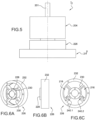
- the test body is shown alone on the Figure 3
- the test body 26 is fixed by one longitudinal end 26.1 to the frame 16 and by the other longitudinal end 26.2 to the magnetorheological brake, i.e. to the housing 8 in the example shown.
- the force sensors are in contact with the test body at its longitudinal end 26.2 secured to the housing 8.
- the test body 26 comprises a cylindrical body with a circular section closed by a bottom 28 at the longitudinal end 26.2.
- An annular collar 30 extends radially outwards at the other longitudinal end 26.1.
- the inner diameter of the test body corresponds to the outer diameter of the housing 8, increased by an operating clearance.
- the bottom of the test body is arranged between the housing and the second flange 20 of the frame 16.
- test body is secured to the frame by means of at least one screw 32 passing through the flange 18 and the collar 30.
- the screws 32 also serve to connect the flange 18 to the side wall 28.
- the bottom 28 of the test body is fixed to the housing 8 by at least one screw 34.
- the test body 26 also comprises an element 36 projecting from its longitudinal end 26.2 opposite that in contact with the housing.
- the element 36 is received in a cavity 38 formed in the flange 20 of the frame.
- the projecting element 36 has the shape of an angular portion centered on the longitudinal axis.
- the angular portion 36 is delimited by two faces 36.1, 36.2.
- the cavity 38 has a shape corresponding to that of the angular portion 36 and is delimited by two faces 38.1 38.2 each facing a face 36.1, 36.2 of the angular portion 36.
- a force sensor 40.1 is mounted on the face 38.1 of the cavity in contact with the face 36.1 of the angular portion and a force sensor 40.2 is mounted on the face 38.2 of the cavity in contact with the face 36.2 of the angular portion 36.
- a point-type mechanical contact is ensured between each force sensor 40.1, 40.2 and the test body 26.
- the force sensors 40.1, 40.2 are advantageously mounted prestressed.
- the test body is, for example, made of plastic material, such as ABS.
- the material of the test body and its geometry can be determined based on the minimum and maximum torque applied, the sensitivity of the force sensors and the desired detection threshold.
- the deformation of the test body is such that it is not perceptible to the user. For example, a deformation of the test body of a few microns can be considered not to be perceptible to the user.
- the forces could be measured directly on the housing 8 or on the rotating shaft, for which a torque sensor would be implemented.
- a torque sensor has a high cost and a large footprint compared to force sensors.
- a torque sensor provides a precise and calibrated torque value while this information is not useful in the context of the invention.
- the force sensor is for example made using piezoresistive elements assembled in the form of a Wheatstone bridge, they allow a sensitivity of the order of a few tens of mV per Newton with a stiffness high enough to limit the displacement to a few tens of microns at full load.
- the force sensor(s) could be replaced by one or more deformation sensors formed, for example, by strain gauges directly applied to the test body to detect its deformation.
- the motor M being mechanically linked to the second flange 16 of the frame, it does not disturb the measurement of the torque on the actuating shaft.
- test body 126 whose general shape is identical to that of the test body 26, but additionally comprises longitudinal slots 127 in the side wall of the test body 126.
- the slots 127 are distributed angularly in a regular manner.
- the test body has in this embodiment a greater capacity for deformation. It is for example made of aluminum alloy.
- means may be provided for amplifying the deformation of the test body under an axial torsional stress while reducing the deformation of the test body for any other stress not relevant within the scope of the invention, such as for example a radial stress which would be applied to the button in a parasitic manner by the user.
- the sensitivity of the detection is thus improved and disturbances or false detections can be eliminated.
- test body of the figures 1 to 4 allows the sensitivity of the measuring device to be increased by arranging the sensors over the largest possible diameter.
- the walls 36.1 and 36.2 of the projecting element are arranged at 90° to each other.
- This positioning associated with a point contact at the level of the force sensors 40.1 and 40.2 makes it possible to decompose the deformation stress of the test body and to favor the sensitivity to the forces according to two orthogonal components located in the plane of the frame 16.
- the sensitivity is greatly reduced for parasitic forces exerted perpendicular to the plane of the frame 16.
- a computational or algorithmic processing on the components of the orthogonal forces measured by the sensors 40.1 and 40.2, such as for example a calculation based on the difference in measurement between the two sensors weighted by the common measurement component of the two sensors in the case of a preferential assembly of the sensors with a prestress of load makes it possible to reduce to a certain extent the sensitivity to parasitic forces exerted parallel to the plane of the frame 16.
- the haptic interface also includes a control unit UC to which the current position sensor, the means for determining the direction of rotation of the button, the torque sensor, the means for generating the magnetic field and the electric motor are connected.
- the control unit processes the signals transmitted by the sensors and generates orders to the means for generating the magnetic field and to the electric motor.
- the user rotates the knob around its axis in a first direction of rotation and brings it into an angular position defined as a stop.
- a magnetic field is applied to the magnetorheological fluid so that its apparent viscosity variation generates a torque at the level of the element interacting with the fluid simulating a stop at the level of the knob in the first direction of rotation.
- test body 26 undergoes a torsion torque via the housing, itself in interaction with the fluid, itself in interaction with the interaction element 12, itself linked to the shaft 2.
- This deformation is measured by the force sensor arranged downstream in the first direction of rotation. Knowing which of the force sensors is stressed makes it possible to know the direction in which the user intends to turn the knob. Preferably, the measurements from the two assembled force sensors can be combined with a load preload to determine the direction in which the user intends to turn the knob. The detection of a minimum torque makes it possible to confirm that the user actually intends to rotate the knob. It is deduced from this that the user intends to hold the knob in the stop position. The magnetic field is maintained so as to oppose a force to the movement of the interaction element 12 via the viscous magnetorheological fluid.
- the force sensor arranged upstream considering the first direction of rotation, which will be stressed.
- the measurements from the two assembled force sensors can be combined with a load preload to determine the new direction in which the user intends to turn the knob.
- the user's intention is deduced from this, this intention is confirmed by the detection of a minimal torque.
- the magnetic field is canceled, the apparent viscosity of the fluid decreases sharply, the interaction element can therefore rotate in the second direction without feeling any sticking effect.
- the invention can thus reproduce the operation of a freewheel.
- an interface I2 comprising a frame 216, a brake 204, a test body 226 having the shape of a wheel and an element for interaction with the user 201, the element for interaction with the fluid not being visible.
- the wheel has a hub 228, an outer ring 232 and spokes 230 connecting the hub 228 to the outer ring 232.
- the hub 228 is secured to the interface housing, for example, by screws passing axially through the hub 228, and the outer ring 232 is secured to the frame, for example, by screws passing axially through the outer ring.
- Two force sensors 240.1, 240.2 are arranged each bearing against a spoke 230 and arranged relative to the spokes such that, when the test body 226 is stressed in a direction of rotation, only one of the sensors is stressed.
- the force sensors are fixed on the frame 216 and bearing against a face of a spoke 230.
- the force sensors could be assembled with a load prestress, or, as mentioned above, be replaced by elongation gauges arranged on the test body and detecting the deformation, for example of the spokes under the effect of the torsional torque. More generally, the force sensors can be replaced by deformation sensors.
- Means for applying mechanical constraints to the test body may advantageously be added, which makes it possible to reduce the number of force sensors by assembling the latter with a load prestress.
- the data from these force or strain sensors are processed by an electronic system to determine whether the torque exerted by the user on the interface exceeds a predetermined threshold.
- the torque sign is also determined and makes it possible to know the direction in which the user intends to move the button.
- the motor M is intended to directly move the shaft 2 and therefore the button at low torque, without this representing a danger for the user. Indeed, the motor is not intended to apply very high torques. Thus the motor can have a small size which facilitates the integration of the motor in the interface and to create a small interface. In addition, since the motor is not intended to operate continuously, the power consumption of the interface is reduced compared to a haptic interface using only an electric motor.
- the haptic interface according to the invention makes it possible to generate a large number of haptic patterns. For illustration purposes, some of them will be described below, but this is not an exhaustive description of the haptic patterns that can be produced by the interface according to the invention.
- the interface includes seals 13 to ensure the sealing of the chamber containing the magnetorheological fluid. These seals exert friction on the shaft 2, generating an idle torque which is detrimental to the haptic feel.
- the motor can be advantageously controlled to compensate for this no-load torque. For example, it is controlled to assist the rotational movement of the knob.
- the motor M can be activated to compensate for the no-load torque when no magnetic field is applied to the magnetorheological fluid. For example, when designing the interface, the no-load torque is measured or estimated, and the control unit is programmed to control the motor so that it compensates for this no-load torque.
- the haptic feeling can be significantly improved by controlling the motor based on knowledge of the user's intention. Indeed, as soon as this intention is detected, the motor is activated to compensate for the no-load torque, so the user may never feel this no-load torque inherent in the friction of the joints. Knowledge of the user's action intention is also beneficial in the case of operating modes implementing both the magnetorheological brake and the motor, the control of these elements being done in a more reactive manner, the transitions are less perceptible by the user.
- the motor can also be operated to generate a vibration, which is transmitted to the actuating shaft since the two shafts are linked in rotation, this vibration giving for example a haptic indication of the alert type.
- the spring effect for example the sensation felt when manipulating a spring, for example a spiral spring, on a rotating axis.
- the interface is controlled to exert, depending on the direction of rotation and the angular position, a force against the rotation of the button or a restoring force on the button.
- a spring is characterized by a stiffness k.
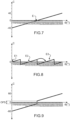
- the control unit generates orders to the magnetic field generation means and to the motor in order to apply to the button the instruction shown on the Figure 7 , the instruction is a linear function whose zero value corresponds to a stable position of the spring whose action on the button we wish to simulate, i.e. its position at rest.
- the Figure 7 represents the variation of the setpoint C as a function of the rotation angle ⁇ , which is here in degrees.
- the 180° angle corresponds to the stable position or rest state of the spring to be simulated
- the generated commands depend on the angular position of the button and the direction of rotation. Indeed, the further one deviates from the stable position E, the greater the force opposing the movement of the actuating shaft.
- the direction of rotation brings the button closer to the stable position, a return force is felt by the user.
- the sign of the force to be applied to the user interaction element depends on the direction of rotation.
- the haptic pattern of a spring can be achieved through different commands.
- the motor is capable of delivering sufficient torque to simulate the spring effect, only the motor is then controlled.
- the haptic pattern is programmed so that the 180° angle is considered the stable position E or rest state of the spring.
- the motor is controlled to generate a torque resisting this rotation.
- the intensity of this torque depends on the difference between the "rest" position and the current position of the button. The greater this difference, the greater the torque generated by the motor, thus simulating the elastic return. If the user releases the button, the torque exerted by the motor will tend to bring the button back to its rest position E. The closer it gets to E, the less torque exerted by the motor. Ultimately, the button returns to the initial position E, the motor control becomes zero and the residual friction of the system immobilizes the interface.
- the magnetorheological brake is controlled to generate the resistive torque when the knob is turned from its equilibrium position.
- the motor is controlled to return the knob to its equilibrium position, when the force on the knob is released, or when it is less than the restoring force of the spring.
- This button works as follows. When the user applies sufficient torque to the button, it moves up a notch and into the next equilibrium position.
- the equilibrium positions are designated E1, E2, E3.
- the knob When the knob deviates for example from the equilibrium position E2, i.e. it is pivoted clockwise or counterclockwise from the angle of 120° without however pivoting to reach the angle 180° or 60° respectively, it returns to its second equilibrium position E2 under the action of the motor M.
- the knob For example when the knob reaches the position of 180, a notch is simulated and the knob moves to the third equilibrium position E3 thanks to the action of the motor which is now controlled with a torque depending on the reference relative to the position E3, and which drives the knob towards the equilibrium position E3.
- This passage from the position at 180° to the position at 240° is shown diagrammatically by the arrow F.
- Instabilities may occur around the stable position(s). For example, depending on the motor used, jerky movements or a lack of movement may appear when a small force is commanded which would be of the order of magnitude of the internal friction of the interface. By providing a jump in force or OFS offset (represented on the Figure 9 ) sufficient at the equilibrium position, the motor is controlled to generate a force greater than the internal friction of the interface.
- the motor is preferably adapted to the application of low torques while the brake can apply high torques. It is then advantageous to provide for controlling the motor so that it applies alone on a first angular range P1 the resistive force, on the range [180°; 280°] in the example shown, then on a second angular range P2, the brake is also activated to apply an additional resistive force in addition to that generated by the motor.
- the force applied by the motor is designated F M and the force applied by the brake is designated F F and the total force is designated F T .
- the implementation of the motor and brake helps minimize abrupt transitions and increase the fluidity of haptic interaction. Haptic interaction is thus improved and the transparency of the interaction is increased.
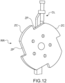
- the haptic interface according to the invention can also make it possible to reproduce the movement of a pawl CL along a ratchet wheel RR shown in the Figure 12 .
- the end of the pawl CL moves on the outer contour of the ratchet wheel RR which has alternating flat areas ZP and concave areas ZC, a concave area connecting to a flat area by a radial plane PR extending along a radius of the wheel.
- a flat area ZP connects to a concave area ZC by an acute angle.
- the brake is controlled to create viscous friction.
- the motor and/or the brake are controlled to simulate a spring effect. If the CL pawl moves counterclockwise or the wheel moves clockwise, a virtual stop is to be simulated when the pawl comes into contact with the radial plane. For this, the brake and/or the motor are controlled to generate sufficient force to simulate a stop.
- the haptic interface according to the invention can be used to simulate a system requiring an absolute representation of the position.
- the motor can be controlled to return the button to a desired position.
- a rotary haptic interface simulating a rotary switch having different notches and comprising a button having a visual reference or marker. If the power supply to the interface is interrupted and the user operates the interface, when the power supply is resumed the motor can reposition the button to its position before the power supply was cut off. In the absence of a motor, the interface cannot reposition itself. This would then result in a discrepancy between the visual reference or marker of the button perceived by the user and the position of the interface expected by the haptic model.
- the system could be controlled as follows.
- the current position of the button is stored regularly in the control electronics. This can be achieved by storing this information in non-volatile memory.
- the system thus has a memory of the last position of the button.
- the control electronics initializes and then compares the current position of the button with the last position recorded in the non-volatile memory.
- the electric motor is then controlled, for example, at a constant speed, until the position of the button is equal to the memorized position.
- the motor can then be stopped and the interface becomes operational.
- a "spring effect" type command can be generated whose stable position corresponds to the last position recorded in the non-volatile memory.
- the button then returns to its last position as if it had been actuated by a return spring.
- haptic patterns described are non-limiting examples.
Landscapes
- Engineering & Computer Science (AREA)
- Physics & Mathematics (AREA)
- General Physics & Mathematics (AREA)
- General Engineering & Computer Science (AREA)
- Automation & Control Theory (AREA)
- Theoretical Computer Science (AREA)
- Human Computer Interaction (AREA)
- Mechanical Control Devices (AREA)
- User Interface Of Digital Computer (AREA)
Claims (15)
- Haptische Schnittstelle, die Folgendes umfasst:- ein Element zur Interaktion (1) mit einem Benutzer, das so ausgebildet ist, dass es sich in eine erste Richtung und in eine zweite Richtung bewegt,- ein Element zur Interaktion (12) mit einer Flüssigkeit, deren Viskosität in Abhängigkeit von einem externen Stimulus variiert, wobei das Element zur Interaktion (12) mit der Flüssigkeit mindestens translatorisch oder mindestens drehend fest mit dem Element zur Interaktion (1) mit dem Benutzer verbunden ist,- Mittel zur Messung einer aktuellen Winkelposition (14) des Elements zur Interaktion (1) mit dem Benutzer,- Mittel zur Bestimmung der Drehrichtung des Elements zur Interaktion (1) mit dem Benutzer,- eine Bremse, die eine Flüssigkeit, deren scheinbare Viskosität in Abhängigkeit von einem äußeren Stimulus variiert, und ein System zur Erzeugung (6) des Stimulus auf Befehl in der Flüssigkeit umfasst, wobei das Element zur Interaktion (12) mit der Flüssigkeit in der Flüssigkeit angeordnet ist,- elektromechanische Drehmittel (M), die eine Welle (M1) umfassen, die mit dem Element zur Interaktion (1) mit dem Benutzer drehfest verbunden ist,- eine Steuereinheit (UC), die so ausgebildet ist, dass sie Befehle für das System zur Erzeugung des Stimulus, um den Stimuluswert zu ändern, und für die elektromechanischen Drehmittel (M) erzeugt, wobei die haptische Schnittstelle dadurch gekennzeichnet ist, dass sie Folgendes umfasst- Mittel zum Erkennen des Drehmoments, das von einem Benutzer auf das Element zur Interaktion (1) mit dem Benutzer ausgeübt wird, im Falle eines Elements zur Interaktion (1) mit dem sich drehenden Benutzer, um die Drehmomentrichtung zu kennen und um zu wissen, ob das Drehmoment für eine bestimmte Richtung größer als ein gegebener Wert ist, wobei die Steuereinheit das System zur Erzeugung (6) des Stimulus basierend auf den über das Drehmoment erhaltenen Informationen zumindest dann steuert, wenn eine Geschwindigkeit von Null des Elements zur Interaktion (1) mit dem Benutzer erkannt wird.
- Haptische Schnittstelle nach Anspruch 1, wobei die elektromechanischen Mittel (M) einen Elektromotor umfassen.
- Haptische Schnittstelle nach Anspruch 1 oder 2, wobei die Mittel zur Bestimmung der Drehrichtung des Elements zur Interaktion mit dem Benutzer durch die Mittel zum Erkennen des von einem Benutzer auf das Element zur Interaktion mit dem Benutzer ausgeübten Drehmoments gebildet werden oder zeitliche Variationen der Mittel zur Messung einer aktuellen Winkelposition (14) des Elements zur Interaktion (1) mit dem Benutzer verwenden,
- Haptische Schnittstelle nach einem der Ansprüche 1 bis 3, wobei die Steuereinheit (UC) so eingerichtet ist, dass sie Befehle an die elektromechanischen Mittel (M) zum Zurückführen des Elements zur Interaktion mit dem Benutzer (1) in mindestens eine gegebene Position erzeugt.
- Haptische Schnittstelle nach einem der Ansprüche 1 bis 4, wobei die Steuereinheit (UC) so eingerichtet ist, dass sie Befehle an die elektromechanischen Mittel (M) und das System zur Erzeugung des Stimulus erzeugt, so dass sie gleichzeitig auf das Element zur Interaktion mit dem Benutzer (1) wirken.
- Haptische Schnittstelle nach einem der Ansprüche 1 bis 5, wobei die Steuereinheit (UC) so eingerichtet ist, dass sie Befehle an die elektromechanischen Mittel (M) erzeugt, damit sie ein Drehmoment auf das Element zur Interaktion mit dem Benutzer (1) anwenden und Reibungen kompensieren, die auf das Element zur Interaktion mit dem Benutzer (1) wirken.
- Haptische Schnittstelle nach einem der Ansprüche 1 bis 6, wobei die Steuereinheit (UC) so eingerichtet ist, dass sie Befehle an die elektromechanischen Mittel (M) und das System zur Erzeugung des Stimulus erzeugt, so dass ab mindestens einer gegebenen Winkelposition des Elements zur Interaktion mit dem Benutzer (1) das System zur Erzeugung des Stimulus auf das Element zur Interaktion mit dem Benutzer (1) wirkt und/oder die elektromechanischen Mittel (M) auf dieses wirken, wenn sich das Element zur Interaktion mit dem Benutzer (1) in eine erste Richtung und in eine zweite Richtung, die der ersten Richtung entgegengesetzt ist, dreht, um der Drehung des Elements zur Interaktion mit dem Benutzer (1) entgegenzuwirken, und so dass die elektromechanischen Mittel (M) die Drehung des Elements zur Interaktion mit dem Benutzer (1) zumindest dann unterstützen, wenn es in die erste Richtung oder in die zweite Richtung in die gegebene Winkelposition geschwenkt wird.
- Haptische Schnittstelle nach Anspruch 7, wobei die Steuereinheit (UC) so eingerichtet ist, dass sie, wenn sich das Element zur Interaktion mit dem Benutzer (1) in der gegebenen Winkelposition befindet, Befehle an die elektromechanischen Mittel (M) und/oder an das System zur Erzeugung des Stimulus erzeugt, eine nicht nullwertige Kraft auf das Element zur Interaktion mit dem Benutzer (1) anzuwenden.
- Haptische Schnittstelle nach Anspruch 7, wobei die Steuereinheit (UC) so eingerichtet ist, dass sie, wenn sich das Element zur Interaktion mit dem Benutzer (1) in einem Winkelbereich auf beiden Seiten der gegebenen Winkelposition befindet, Befehle an die elektromechanischen Mittel (M) und/oder das System zur Erzeugung des Stimulus erzeugt, keine Kraft auf das Element zur Interaktion mit dem Benutzer (1) anzuwenden.
- Haptische Schnittstelle nach einem der Ansprüche 1 bis 9, wobei die Mittel zum Erkennen des vom Benutzer auf das Element zur Interaktion mit dem Benutzer (1) angewandten Drehmoments bzw. der Kraft mindestens einen Kraftsensor (40.1, 40.2, 240.1, 240.2) umfassen, der vorzugsweise vorgespannt montiert ist.
- Haptische Schnittstelle nach einem der Ansprüche 1 bis 10, wobei die Mittel zum Erkennen des Drehmoments mindestens einen Sensor der durch das Drehmoment oder die Kraft verursachten Verformung eines der Elemente der haptischen Schnittstelle umfassen.
- Haptische Schnittstelle nach einem der Ansprüche 1 bis 11, die einen Prüfkörper (26, 126, 226) umfasst, der so angeordnet ist, dass er durch das vom Benutzer auf das Element zur Interaktion (1) mit dem Benutzer angewandte Drehmoment verformt wird, wobei die Mittel zum Erkennen des Drehmoments oder der Kraft mit dem Prüfkörper (26, 126, 226) in Kontakt stehen.
- Haptische Schnittstelle nach einem der Ansprüche 1 bis 12, wobei die Flüssigkeit eine magnetrheologische Flüssigkeit ist, wobei der Stimulus ein Magnetfeld ist.
- Verfahren zur Steuerung einer haptischen Schnittstelle nach einem der Ansprüche 1 bis 13, umfassend die folgenden Schritte:- Bestimmen der Geschwindigkeit des Elements zur Interaktion (1) mit dem Benutzer anhand der Informationen, die von den Mitteln zur Messung der aktuellen Position des Elements zur Interaktion (1) mit dem Benutzer bereitgestellt werden,- Bestimmen des Drehmoments, das auf das Element zur Interaktion (1) mit dem Benutzer angewandt wird,- Bestimmen der aktuellen Position des Elements zur Interaktion (1) mit dem Benutzer,- wenn die Geschwindigkeit größer als eine gegebene Geschwindigkeit ist, ist die Drehrichtung die durch die Geschwindigkeit vorgegebene und das System zur Erzeugung eines Stimulus wird so gesteuert, dass es das für die bestimmte aktuelle Position und für die bestimmte Drehrichtung aufgezeichnete haptische Muster anwendet,- wenn die Geschwindigkeit kleiner als eine gegebene Geschwindigkeit ist und das Drehmoment oder die Kraft größer als ein positiver Schwellenwert oder kleiner als ein negativer Schwellenwert ist, wird die Bewegungsrichtung des Elements zur Interaktion (1) mit dem Benutzer aus dem bestimmten Drehmoment oder der bestimmten Kraft abgeleitet, und das System zur Erzeugung eines Stimulus wird so gesteuert, dass es einen Stimulus in Abhängigkeit von dem aufgezeichneten haptischen Musters für die aktuelle Position und für die abgeleitete Bewegungsrichtung anwendet.
- Verfahren nach Anspruch 14, wobei, wenn das bestimmte Drehmoment kleiner als ein gegebener Wert ist, kein Stimulus auf die Flüssigkeit angewandt wird.
Applications Claiming Priority (2)
| Application Number | Priority Date | Filing Date | Title |
|---|---|---|---|
| FR1559502A FR3042046B1 (fr) | 2015-10-06 | 2015-10-06 | Interface haptique hybride a rendu haptique ameliore |
| PCT/EP2016/073839 WO2017060330A1 (fr) | 2015-10-06 | 2016-10-06 | Interface haptique hybride a rendu haptique ameliore |
Publications (2)
| Publication Number | Publication Date |
|---|---|
| EP3360026A1 EP3360026A1 (de) | 2018-08-15 |
| EP3360026B1 true EP3360026B1 (de) | 2025-05-07 |
Family
ID=55178126
Family Applications (1)
| Application Number | Title | Priority Date | Filing Date |
|---|---|---|---|
| EP16781337.7A Active EP3360026B1 (de) | 2015-10-06 | 2016-10-06 | Hybride haptische schnittstelle mit verbesserter haptischer rückkopplung |
Country Status (6)
| Country | Link |
|---|---|
| US (1) | US10963051B2 (de) |
| EP (1) | EP3360026B1 (de) |
| JP (1) | JP6800222B2 (de) |
| CN (1) | CN108139765B (de) |
| FR (1) | FR3042046B1 (de) |
| WO (1) | WO2017060330A1 (de) |
Families Citing this family (15)
| Publication number | Priority date | Publication date | Assignee | Title |
|---|---|---|---|---|
| US10396633B2 (en) * | 2016-03-20 | 2019-08-27 | Eric K. Wang | Haptic device |
| EP3614229B1 (de) * | 2017-04-21 | 2021-12-29 | Alps Alpine Co., Ltd. | Drehbare betriebsvorrichtung, verfahren zur steuerung davon und programm |
| DE102017210442A1 (de) * | 2017-06-21 | 2018-12-27 | Zf Friedrichshafen Ag | Dehsteuervorrichtung |
| JP6839285B2 (ja) * | 2017-08-03 | 2021-03-03 | アルプスアルパイン株式会社 | トルク発生装置 |
| WO2019131453A1 (ja) * | 2017-12-28 | 2019-07-04 | アルプスアルパイン株式会社 | 入力装置 |
| FR3086076B1 (fr) * | 2018-09-13 | 2021-07-30 | Safran Electronics & Defense | Dispositif d'application d'effort pour un mini-manche actif |
| DE102018222844B3 (de) * | 2018-12-21 | 2020-04-16 | Audi Ag | Drehsteller und Kalibrierverfahren |
| CN110187002B (zh) * | 2019-06-03 | 2023-01-06 | 南昌航空大学 | 一种非电定量感磁装置 |
| WO2020261663A1 (ja) | 2019-06-27 | 2020-12-30 | アルプスアルパイン株式会社 | 操作装置 |
| DE102019135026A1 (de) * | 2019-12-18 | 2021-06-24 | Inventus Engineering Gmbh | Gerätekomponente mit einer magnetorheologischen Bremseinrichtung |
| KR20230088708A (ko) * | 2020-10-15 | 2023-06-20 | 로오드 코포레이션 | 드럼 촉각적 피드백 장치 조향 유닛 및 방법 |
| FR3118672A1 (fr) | 2021-01-05 | 2022-07-08 | Commissariat A L'energie Atomique Et Aux Energies Alternatives | Interface haptique a temps de reactivite augmente |
| WO2023047649A1 (ja) * | 2021-09-24 | 2023-03-30 | アルプスアルパイン株式会社 | 回転検出装置およびスタイラスペン |
| CN119384652A (zh) * | 2022-07-04 | 2025-01-28 | Ck高新材料有限公司 | 触觉输入装置 |
| CN117901816B (zh) * | 2024-03-07 | 2024-07-02 | 博世汽车部件(苏州)有限公司 | 力反馈组件、刹车系统及力反馈控制方法 |
Citations (2)
| Publication number | Priority date | Publication date | Assignee | Title |
|---|---|---|---|---|
| US20060054427A1 (en) * | 2004-09-10 | 2006-03-16 | Alexander Jasso | Systems and methods for providing a haptic device |
| US20060197741A1 (en) * | 2005-03-03 | 2006-09-07 | Biggadike Christopher S A | Haptic feedback device |
Family Cites Families (13)
| Publication number | Priority date | Publication date | Assignee | Title |
|---|---|---|---|---|
| US6283859B1 (en) * | 1998-11-10 | 2001-09-04 | Lord Corporation | Magnetically-controllable, active haptic interface system and apparatus |
| JP4180271B2 (ja) * | 2001-11-20 | 2008-11-12 | アルプス電気株式会社 | 力覚ディバイス |
| JP2006176001A (ja) * | 2004-12-22 | 2006-07-06 | Toyota Motor Corp | ペダル反力制御装置 |
| US8174512B2 (en) * | 2006-06-02 | 2012-05-08 | Immersion Corporation | Hybrid haptic device utilizing mechanical and programmable haptic effects |
| FR2930654B1 (fr) * | 2008-04-29 | 2013-02-08 | Commissariat Energie Atomique | Interface haptique a effort de freinage augmente |
| AU2009303298B2 (en) * | 2008-10-10 | 2013-05-23 | Internet Services, Llc | Haptic output device for use with haptic encoded media |
| US9305120B2 (en) * | 2011-04-29 | 2016-04-05 | Bryan Marc Failing | Sports board configuration |
| DE102012112247A1 (de) * | 2012-12-13 | 2014-06-18 | How To Organize (H2O) Gmbh | Griffelement und Greifereingabemodul für ein haptisches Eingabesystem |
| FR3010550B1 (fr) * | 2013-09-09 | 2019-11-01 | Dav | Procede et interface de commande a retour haptique pour vehicule automobile |
| FR3010547B1 (fr) * | 2013-09-09 | 2016-12-23 | Dav | Interface de commande a retour haptique |
| FR3010548B1 (fr) * | 2013-09-09 | 2016-12-23 | Dav | Interface de commande a retour haptique |
| DE102014225114A1 (de) * | 2013-12-09 | 2015-06-11 | Kostal Of America | Drehschalter mit programmierbaren Endanschlägen und variabler taktiler Rückmeldung |
| WO2015175697A1 (en) * | 2014-05-13 | 2015-11-19 | Schlage Lock Company Llc | Lock device having position sensor |
-
2015
- 2015-10-06 FR FR1559502A patent/FR3042046B1/fr active Active
-
2016
- 2016-10-06 EP EP16781337.7A patent/EP3360026B1/de active Active
- 2016-10-06 CN CN201680058750.1A patent/CN108139765B/zh active Active
- 2016-10-06 US US15/765,748 patent/US10963051B2/en active Active
- 2016-10-06 JP JP2018517277A patent/JP6800222B2/ja active Active
- 2016-10-06 WO PCT/EP2016/073839 patent/WO2017060330A1/fr not_active Ceased
Patent Citations (2)
| Publication number | Priority date | Publication date | Assignee | Title |
|---|---|---|---|---|
| US20060054427A1 (en) * | 2004-09-10 | 2006-03-16 | Alexander Jasso | Systems and methods for providing a haptic device |
| US20060197741A1 (en) * | 2005-03-03 | 2006-09-07 | Biggadike Christopher S A | Haptic feedback device |
Also Published As
| Publication number | Publication date |
|---|---|
| FR3042046A1 (fr) | 2017-04-07 |
| EP3360026A1 (de) | 2018-08-15 |
| US20180284891A1 (en) | 2018-10-04 |
| US10963051B2 (en) | 2021-03-30 |
| JP2018532196A (ja) | 2018-11-01 |
| FR3042046B1 (fr) | 2017-10-20 |
| JP6800222B2 (ja) | 2020-12-16 |
| CN108139765B (zh) | 2020-06-19 |
| CN108139765A (zh) | 2018-06-08 |
| WO2017060330A1 (fr) | 2017-04-13 |
Similar Documents
| Publication | Publication Date | Title |
|---|---|---|
| WO2017060330A1 (fr) | Interface haptique hybride a rendu haptique ameliore | |
| EP3201725B1 (de) | Haptische schnittstelle mit verbessertem haptischem rendering | |
| EP3227761B1 (de) | Haptische schnittstelle mit verbesserter haptischer rückmeldung, insbesondere bei der wiedergabe eines stopps | |
| EP3201732B1 (de) | Haptische schnittstelle mit verbesserter steuerung der haptischen empfindung | |
| EP2274660B1 (de) | Kraftrückkoppelungsschnittstelle mit verbesserten wahrnehmungen | |
| EP3516483B1 (de) | Haptische schnittstelle mit mindestens zwei freiheitsgraden mit verbessertem haptischem empfinden | |
| EP2269128B1 (de) | Haptische schnittstellenvorrichtung mit verstärkte bremskraft | |
| EP2304523B1 (de) | Vorrichtung zur haptischen feedback-steuerung | |
| EP4154088A1 (de) | Steuerschnittstelle mit haptischem feedback | |
| EP3485349A1 (de) | Haptische vorrichtung mit vibrationsbasierter schmierung | |
| FR2566550A1 (fr) | Unite d'asservissement electromagnetique | |
| WO2000063059A1 (fr) | Dispositif de rappel au point neutre, en particulier pour volant | |
| WO2023079247A1 (fr) | Dispositif d'application d'effort de manche de pilotage, manche, procédé, programme et aéronef | |
| EP0966049B1 (de) | Piezoelektrischer Motor mit integriertem Positionssensor | |
| EP3215911A1 (de) | Steuerungsverfahren und -schnittstelle zur haptischen rückmeldung für ein kraftfahrzeug | |
| EP0027407B1 (de) | Vorrichtung zum Feststellen eines Unterschiedes zwischen den Umlaufgeschwindigkeiten von zwei sich drehenden Wellen und Anwendung bei einer Messung oder Regelung | |
| FR3026501A1 (fr) | Procede et interface de commande a retour haptique pour vehicule automobile | |
| EP1647872A1 (de) | Bedienungselement mit verbesserter Einrichtung für die Versorgung einer Rückstellkraft | |
| WO2023084123A1 (fr) | Dispositif de detection de position relative avec coupe-circuit |
Legal Events
| Date | Code | Title | Description |
|---|---|---|---|
| STAA | Information on the status of an ep patent application or granted ep patent |
Free format text: STATUS: THE INTERNATIONAL PUBLICATION HAS BEEN MADE |
|
| PUAI | Public reference made under article 153(3) epc to a published international application that has entered the european phase |
Free format text: ORIGINAL CODE: 0009012 |
|
| STAA | Information on the status of an ep patent application or granted ep patent |
Free format text: STATUS: REQUEST FOR EXAMINATION WAS MADE |
|
| 17P | Request for examination filed |
Effective date: 20180410 |
|
| AK | Designated contracting states |
Kind code of ref document: A1 Designated state(s): AL AT BE BG CH CY CZ DE DK EE ES FI FR GB GR HR HU IE IS IT LI LT LU LV MC MK MT NL NO PL PT RO RS SE SI SK SM TR |
|
| AX | Request for extension of the european patent |
Extension state: BA ME |
|
| DAV | Request for validation of the european patent (deleted) | ||
| DAX | Request for extension of the european patent (deleted) | ||
| RIC1 | Information provided on ipc code assigned before grant |
Ipc: G05G 5/03 20080401AFI20170426BHEP Ipc: G06F 3/01 20060101ALI20170426BHEP |
|
| STAA | Information on the status of an ep patent application or granted ep patent |
Free format text: STATUS: EXAMINATION IS IN PROGRESS |
|
| 17Q | First examination report despatched |
Effective date: 20211206 |
|
| RAP3 | Party data changed (applicant data changed or rights of an application transferred) |
Owner name: COMMISSARIAT A L'ENERGIE ATOMIQUE ET AUX ENERGIESALTERNATIVES |
|
| GRAP | Despatch of communication of intention to grant a patent |
Free format text: ORIGINAL CODE: EPIDOSNIGR1 |
|
| STAA | Information on the status of an ep patent application or granted ep patent |
Free format text: STATUS: GRANT OF PATENT IS INTENDED |
|
| RIC1 | Information provided on ipc code assigned before grant |
Ipc: G06F 3/01 20060101ALI20241211BHEP Ipc: G05G 1/08 20060101ALI20241211BHEP Ipc: G05G 5/03 20080401AFI20241211BHEP |
|
| INTG | Intention to grant announced |
Effective date: 20250109 |
|
| GRAS | Grant fee paid |
Free format text: ORIGINAL CODE: EPIDOSNIGR3 |
|
| GRAA | (expected) grant |
Free format text: ORIGINAL CODE: 0009210 |
|
| STAA | Information on the status of an ep patent application or granted ep patent |
Free format text: STATUS: THE PATENT HAS BEEN GRANTED |
|
| AK | Designated contracting states |
Kind code of ref document: B1 Designated state(s): AL AT BE BG CH CY CZ DE DK EE ES FI FR GB GR HR HU IE IS IT LI LT LU LV MC MK MT NL NO PL PT RO RS SE SI SK SM TR |
|
| REG | Reference to a national code |
Ref country code: GB Ref legal event code: FG4D Free format text: NOT ENGLISH |
|
| REG | Reference to a national code |
Ref country code: CH Ref legal event code: EP |
|
| REG | Reference to a national code |
Ref country code: DE Ref legal event code: R096 Ref document number: 602016092171 Country of ref document: DE |
|
| REG | Reference to a national code |
Ref country code: IE Ref legal event code: FG4D Free format text: LANGUAGE OF EP DOCUMENT: FRENCH |
|
| REG | Reference to a national code |
Ref country code: NL Ref legal event code: MP Effective date: 20250507 |
|
| PG25 | Lapsed in a contracting state [announced via postgrant information from national office to epo] |
Ref country code: PT Free format text: LAPSE BECAUSE OF FAILURE TO SUBMIT A TRANSLATION OF THE DESCRIPTION OR TO PAY THE FEE WITHIN THE PRESCRIBED TIME-LIMIT Effective date: 20250908 Ref country code: ES Free format text: LAPSE BECAUSE OF FAILURE TO SUBMIT A TRANSLATION OF THE DESCRIPTION OR TO PAY THE FEE WITHIN THE PRESCRIBED TIME-LIMIT Effective date: 20250507 Ref country code: FI Free format text: LAPSE BECAUSE OF FAILURE TO SUBMIT A TRANSLATION OF THE DESCRIPTION OR TO PAY THE FEE WITHIN THE PRESCRIBED TIME-LIMIT Effective date: 20250507 |
|
| REG | Reference to a national code |
Ref country code: LT Ref legal event code: MG9D |
|
| PG25 | Lapsed in a contracting state [announced via postgrant information from national office to epo] |
Ref country code: NO Free format text: LAPSE BECAUSE OF FAILURE TO SUBMIT A TRANSLATION OF THE DESCRIPTION OR TO PAY THE FEE WITHIN THE PRESCRIBED TIME-LIMIT Effective date: 20250807 Ref country code: GR Free format text: LAPSE BECAUSE OF FAILURE TO SUBMIT A TRANSLATION OF THE DESCRIPTION OR TO PAY THE FEE WITHIN THE PRESCRIBED TIME-LIMIT Effective date: 20250808 |
|
| PG25 | Lapsed in a contracting state [announced via postgrant information from national office to epo] |
Ref country code: NL Free format text: LAPSE BECAUSE OF FAILURE TO SUBMIT A TRANSLATION OF THE DESCRIPTION OR TO PAY THE FEE WITHIN THE PRESCRIBED TIME-LIMIT Effective date: 20250507 Ref country code: PL Free format text: LAPSE BECAUSE OF FAILURE TO SUBMIT A TRANSLATION OF THE DESCRIPTION OR TO PAY THE FEE WITHIN THE PRESCRIBED TIME-LIMIT Effective date: 20250507 |
|
| REG | Reference to a national code |
Ref country code: AT Ref legal event code: MK05 Ref document number: 1793175 Country of ref document: AT Kind code of ref document: T Effective date: 20250507 |
|
| PG25 | Lapsed in a contracting state [announced via postgrant information from national office to epo] |
Ref country code: BG Free format text: LAPSE BECAUSE OF FAILURE TO SUBMIT A TRANSLATION OF THE DESCRIPTION OR TO PAY THE FEE WITHIN THE PRESCRIBED TIME-LIMIT Effective date: 20250507 |
|
| PG25 | Lapsed in a contracting state [announced via postgrant information from national office to epo] |
Ref country code: HR Free format text: LAPSE BECAUSE OF FAILURE TO SUBMIT A TRANSLATION OF THE DESCRIPTION OR TO PAY THE FEE WITHIN THE PRESCRIBED TIME-LIMIT Effective date: 20250507 |
|
| PG25 | Lapsed in a contracting state [announced via postgrant information from national office to epo] |
Ref country code: AT Free format text: LAPSE BECAUSE OF FAILURE TO SUBMIT A TRANSLATION OF THE DESCRIPTION OR TO PAY THE FEE WITHIN THE PRESCRIBED TIME-LIMIT Effective date: 20250507 |
|
| PG25 | Lapsed in a contracting state [announced via postgrant information from national office to epo] |
Ref country code: RS Free format text: LAPSE BECAUSE OF FAILURE TO SUBMIT A TRANSLATION OF THE DESCRIPTION OR TO PAY THE FEE WITHIN THE PRESCRIBED TIME-LIMIT Effective date: 20250807 |
|
| PG25 | Lapsed in a contracting state [announced via postgrant information from national office to epo] |
Ref country code: IS Free format text: LAPSE BECAUSE OF FAILURE TO SUBMIT A TRANSLATION OF THE DESCRIPTION OR TO PAY THE FEE WITHIN THE PRESCRIBED TIME-LIMIT Effective date: 20250907 |
|
| PG25 | Lapsed in a contracting state [announced via postgrant information from national office to epo] |
Ref country code: LV Free format text: LAPSE BECAUSE OF FAILURE TO SUBMIT A TRANSLATION OF THE DESCRIPTION OR TO PAY THE FEE WITHIN THE PRESCRIBED TIME-LIMIT Effective date: 20250507 |
|
| PG25 | Lapsed in a contracting state [announced via postgrant information from national office to epo] |
Ref country code: SM Free format text: LAPSE BECAUSE OF FAILURE TO SUBMIT A TRANSLATION OF THE DESCRIPTION OR TO PAY THE FEE WITHIN THE PRESCRIBED TIME-LIMIT Effective date: 20250507 Ref country code: DK Free format text: LAPSE BECAUSE OF FAILURE TO SUBMIT A TRANSLATION OF THE DESCRIPTION OR TO PAY THE FEE WITHIN THE PRESCRIBED TIME-LIMIT Effective date: 20250507 |
|
| PG25 | Lapsed in a contracting state [announced via postgrant information from national office to epo] |
Ref country code: CZ Free format text: LAPSE BECAUSE OF FAILURE TO SUBMIT A TRANSLATION OF THE DESCRIPTION OR TO PAY THE FEE WITHIN THE PRESCRIBED TIME-LIMIT Effective date: 20250507 |
|
| PG25 | Lapsed in a contracting state [announced via postgrant information from national office to epo] |
Ref country code: EE Free format text: LAPSE BECAUSE OF FAILURE TO SUBMIT A TRANSLATION OF THE DESCRIPTION OR TO PAY THE FEE WITHIN THE PRESCRIBED TIME-LIMIT Effective date: 20250507 |
|
| PG25 | Lapsed in a contracting state [announced via postgrant information from national office to epo] |
Ref country code: SK Free format text: LAPSE BECAUSE OF FAILURE TO SUBMIT A TRANSLATION OF THE DESCRIPTION OR TO PAY THE FEE WITHIN THE PRESCRIBED TIME-LIMIT Effective date: 20250507 Ref country code: RO Free format text: LAPSE BECAUSE OF FAILURE TO SUBMIT A TRANSLATION OF THE DESCRIPTION OR TO PAY THE FEE WITHIN THE PRESCRIBED TIME-LIMIT Effective date: 20250507 |
|
| PG25 | Lapsed in a contracting state [announced via postgrant information from national office to epo] |
Ref country code: IT Free format text: LAPSE BECAUSE OF FAILURE TO SUBMIT A TRANSLATION OF THE DESCRIPTION OR TO PAY THE FEE WITHIN THE PRESCRIBED TIME-LIMIT Effective date: 20250507 |
|
| REG | Reference to a national code |
Ref country code: DE Ref legal event code: R097 Ref document number: 602016092171 Country of ref document: DE |
|
| PLBE | No opposition filed within time limit |
Free format text: ORIGINAL CODE: 0009261 |
|
| STAA | Information on the status of an ep patent application or granted ep patent |
Free format text: STATUS: NO OPPOSITION FILED WITHIN TIME LIMIT |
|
| REG | Reference to a national code |
Ref country code: CH Ref legal event code: L10 Free format text: ST27 STATUS EVENT CODE: U-0-0-L10-L00 (AS PROVIDED BY THE NATIONAL OFFICE) Effective date: 20260318 |
|
| 26N | No opposition filed |
Effective date: 20260210 |