EP3359780B1 - Ein dampfturbinen ventil, welches kreisförmige segmente beinhaltet - Google Patents
Ein dampfturbinen ventil, welches kreisförmige segmente beinhaltet Download PDFInfo
- Publication number
- EP3359780B1 EP3359780B1 EP16775262.5A EP16775262A EP3359780B1 EP 3359780 B1 EP3359780 B1 EP 3359780B1 EP 16775262 A EP16775262 A EP 16775262A EP 3359780 B1 EP3359780 B1 EP 3359780B1
- Authority
- EP
- European Patent Office
- Prior art keywords
- rotor
- valve
- turbine
- flow
- segments
- Prior art date
- Legal status (The legal status is an assumption and is not a legal conclusion. Google has not performed a legal analysis and makes no representation as to the accuracy of the status listed.)
- Active
Links
Images





Classifications
-
- F—MECHANICAL ENGINEERING; LIGHTING; HEATING; WEAPONS; BLASTING
- F01—MACHINES OR ENGINES IN GENERAL; ENGINE PLANTS IN GENERAL; STEAM ENGINES
- F01K—STEAM ENGINE PLANTS; STEAM ACCUMULATORS; ENGINE PLANTS NOT OTHERWISE PROVIDED FOR; ENGINES USING SPECIAL WORKING FLUIDS OR CYCLES
- F01K7/00—Steam engine plants characterised by the use of specific types of engine; Plants or engines characterised by their use of special steam systems, cycles or processes; Control means specially adapted for such systems, cycles or processes; Use of withdrawn or exhaust steam for feed-water heating
- F01K7/16—Steam engine plants characterised by the use of specific types of engine; Plants or engines characterised by their use of special steam systems, cycles or processes; Control means specially adapted for such systems, cycles or processes; Use of withdrawn or exhaust steam for feed-water heating the engines being only of turbine type
- F01K7/165—Controlling means specially adapted therefor
-
- F—MECHANICAL ENGINEERING; LIGHTING; HEATING; WEAPONS; BLASTING
- F01—MACHINES OR ENGINES IN GENERAL; ENGINE PLANTS IN GENERAL; STEAM ENGINES
- F01D—NON-POSITIVE DISPLACEMENT MACHINES OR ENGINES, e.g. STEAM TURBINES
- F01D17/00—Regulating or controlling by varying flow
-
- F—MECHANICAL ENGINEERING; LIGHTING; HEATING; WEAPONS; BLASTING
- F01—MACHINES OR ENGINES IN GENERAL; ENGINE PLANTS IN GENERAL; STEAM ENGINES
- F01D—NON-POSITIVE DISPLACEMENT MACHINES OR ENGINES, e.g. STEAM TURBINES
- F01D17/00—Regulating or controlling by varying flow
- F01D17/10—Final actuators
-
- F—MECHANICAL ENGINEERING; LIGHTING; HEATING; WEAPONS; BLASTING
- F01—MACHINES OR ENGINES IN GENERAL; ENGINE PLANTS IN GENERAL; STEAM ENGINES
- F01D—NON-POSITIVE DISPLACEMENT MACHINES OR ENGINES, e.g. STEAM TURBINES
- F01D17/00—Regulating or controlling by varying flow
- F01D17/10—Final actuators
- F01D17/12—Final actuators arranged in stator parts
- F01D17/14—Final actuators arranged in stator parts varying effective cross-sectional area of nozzles or guide conduits
-
- F—MECHANICAL ENGINEERING; LIGHTING; HEATING; WEAPONS; BLASTING
- F01—MACHINES OR ENGINES IN GENERAL; ENGINE PLANTS IN GENERAL; STEAM ENGINES
- F01D—NON-POSITIVE DISPLACEMENT MACHINES OR ENGINES, e.g. STEAM TURBINES
- F01D17/00—Regulating or controlling by varying flow
- F01D17/10—Final actuators
- F01D17/12—Final actuators arranged in stator parts
- F01D17/14—Final actuators arranged in stator parts varying effective cross-sectional area of nozzles or guide conduits
- F01D17/141—Final actuators arranged in stator parts varying effective cross-sectional area of nozzles or guide conduits by means of shiftable members or valves obturating part of the flow path
- F01D17/145—Final actuators arranged in stator parts varying effective cross-sectional area of nozzles or guide conduits by means of shiftable members or valves obturating part of the flow path by means of valves, e.g. for steam turbines
-
- F—MECHANICAL ENGINEERING; LIGHTING; HEATING; WEAPONS; BLASTING
- F02—COMBUSTION ENGINES; HOT-GAS OR COMBUSTION-PRODUCT ENGINE PLANTS
- F02C—GAS-TURBINE PLANTS; AIR INTAKES FOR JET-PROPULSION PLANTS; CONTROLLING FUEL SUPPLY IN AIR-BREATHING JET-PROPULSION PLANTS
- F02C9/00—Controlling gas-turbine plants; Controlling fuel supply in air- breathing jet-propulsion plants
Definitions
- power e.g., electrical power
- moving fluid e.g., liquids and gasses
- US 2015/226089 A1 discloses a grid valve assembly for a steam turbine.
- turbo-machinery can embody turbines and power generating equipment, as well as pumps, compressors, and blowers, wherein at least one difference between different types of equipment may reside in the operating pressure of working fluid that exits the machine.
- Some embodiments can vary flow parameters of working fluid that flows in a turbine.
- the turbine can include a rotor and a stator, each with blades disposed in the flowpath to guide and regulate flow properties of steam.
- the embodiment can reside in the flowpath to regulate the flow of steam that impinges on the blades and, in turn, cause the steam to exit the turbine to an extraction unit. Examples of the extraction unit can divert the steam to operate boilers, heaters, and like equipment that is collateral to the turbine.
- turbines that incorporate the embodiments can forego external valves and collateral equipment necessary to regulate flow of extracted steam. This feature simplifies construction and, effectively, reduces costs of the machine. Moreover, these turbines may enjoy smaller and/or reduced footprints, which can simplify shipping, handling, and installation at a facility.
- a turbine comprising a rotor with a rotor blade and a valve assembly disposed upstream of the rotor blade, the valve assembly comprising a plurality of segments that form a ring, wherein the plurality of segments are configured to move radially inwardly and outwardly to regulate flow of a working fluid across the blade.
- a valve assembly comprising a body member having a plurality of individual arcuate segments, a plurality of coupling members, one each disposed between adjacent ones of the individual arcuate segments, and an actuator coupled with the plurality of individual arcuate segments, wherein the body member is configured so that actuation of the actuator causes the individual arcuate segments to move to the same position.
- a method for regulating flow of steam in a turbine comprising varying an aperture downstream of a rotor blade to direct flow of fluid to an extraction unit.
- the discussion below describes embodiments of a valve for use to regulate flow of fluid in a turbine.
- the embodiments can deploy in the turbine, often having structure that circumscribes part of the rotor. This structure may define an aperture that receives the rotor. Actuation of the structure can change the size of the aperture to "open” and “close” the valve relative to the rotor. These changes can vary the flow of fluid across the rotor and in contact with the rotor blades and, in one example, a second flow of fluid that exits the turbine.
- the second flow of fluid can be directed to other parts of the turbine or collateral equipment, in general.
- the second flow of fluid can operate a boiler (also, "heater”) that provides feedwater to a steam generator. This steam generator can generate the steam to operate the turbine.
- Other embodiments and implementations are within the scope of the disclosed subject matter.
- FIG. 1 depicts a schematic diagram of an exemplary embodiment of a valve 100 that can facilitate extraction of steam from a turbine.
- the valve 100 can be disposed in a power generating system 102 (also, "system 102").
- the system 102 can embody a turbine or like apparatus that may be configured to generate power (e.g., electrical power) from a flow of working fluid F.
- working fluid F include steam, often under high pressure, although the system 102 may use water and/or other fluids and gasses.
- the system 102 can have a casing 104 that forms the base structure for the machine.
- the casing 104 may define a fluid pathway 106 with a first end 108 (also, "inlet 108") and a second end 110 (also, "outlet 110").
- the fluid pathway 106 may be generally annular with an axis 112 that extends longitudinally between the ends 108, 110.
- the system 102 may include a rotor 114 that resides in the fluid pathway 106.
- the rotor 114 can have a rotor body 116 that extends through the valve 100.
- the body 116 has an outer surface 118 having one or more rotor blades 120 formed thereon. As also shown in FIG.
- the system 102 can also include a stator blade assembly 124 interposed between the valve 100 and the rotor blades 120.
- the stator blade assembly 124 can include a blade carrier 126, typically a plate or like structure that circumscribes the rotor 114 and couples with the casing 104.
- One or more stator blades 128 can populate the circumference of this plate.
- the casing 104 may be configured to allow some of the fluid F to escape or exit the system 102.
- this configuration employs one or more openings (e.g., a first opening 130).
- the openings 130 can allow the fluid pathway 106 to communicate (as second flow F 2 ) with a conduit 132 (e.g., a pipe) that couples with the casing 104.
- the conduit 132 can also couple with other parts of the system 102 or with collateral equipment, as desired. Often, this collateral equipment is part of a heating system that boils water to provide steam for the fluid F.
- fluid F flows (as first flow F 1 ) through the fluid pathway 106.
- the flow can bifurcate into the second flow F 2 and a third flow F 3 , which can contact with the rotor blades 120 to induce rotation of the rotor 114, as indicated by the arrow identified with the numeral 122.
- the stator blades 128 are useful to manage flow characteristics of the third flow F 3 .
- the valve 100 may be used to regulate the flows F 2 , F 3 .
- the valve 100 may define a flow area 134 that can change in size relative to the rotor body 116. These changes regulate parameters for the flow of working fluid F across the rotor 114 (as the third flow F 3 ) and, also, the flow of working fluid F out of the openings 130 (as the second flow F 2 ).
- the third flow F 3 causes rotation 122 of the rotor 114 to generate power in the system 102.
- the second flow F 2 can enter the conduit 132 for use in equipment that pre-heats water before the water is boiled into steam for use as the working fluid F.
- valve 100 to regulate the parameters of the flows F 2 , F 3 from inside the fluid pathway 106 eliminates many collateral devices (e.g., valves, conduits, etc.) that might be necessary to regulate extraction of working fluid from the system 102 as the second flow F 2 .
- This feature can reduce the footprint and/or operating envelope for the system 102. This smaller, more compact design may be easier to move and install at an installation site.
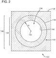
- FIG. 2 illustrates an elevation view of the cross-section of the system 102 taken at line 2-2 of FIG. 1 .
- This example includes a body member 136 with a form factor that is circular or annular, although this disclosure contemplates other shapes (e.g., rectangular, square, oval, etc.) for use as the form factor as well.
- the body member 136 forms a ring 138 with an inner peripheral edge 140 disposed circumferentially around a center 142.
- the inner peripheral edge 140 can bound an aperture 144 that forms the flow area 134.
- the aperture 144 can have a radius R as measured between the inner peripheral edge 140 and the center 142.
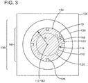
- FIG. 3 illustrates the elevation view of FIG. 2 with the rotor 114 in position in the fluid pathway 106 ( FIG. 1 ). This position locates the rotor 114 so that the inner peripheral edge 140 is spaced apart from the outer surface 118 of the rotor 114 by a distance D. This spacing forms an annular gap 146.
- the third flow F 3 flows through the annular gap 146 to impinge on the rotor blades 120 and stator blades 128. Actuation of the body member 136 can vary the distance D to modify the annular gap 146 and, in turn, regulate flow parameters of the second flow F 2 and also the third flow F 3 , discussed above.
- the value of the distance D may be approximately uniform circumferentially around the center 142, taking into consideration design and manufacturing tolerances of the ring 138, the valve 100, and the components of the system 102 generally. In other implementations, the value for the distance D may not be uniform or may vary circumferentially around the center 142 because of the form factor and/or construction of the body member 136.
- the discussion below describes one construction with multiple parts, or segments, that make up the ring 138. Dimensions for the segments can result in variations of the distance D substantially consistent with the aperture 144 having a plurality of lobes or bulges.
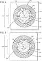
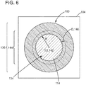
- FIG. 4, 5 , and 6 depict the elevation view of FIG. 3 with the valve 100 in various configurations to modify the distance D of the annular gap 146. These configurations are useful to illustrate operation of this example of the valve 100 to regulate flow of working fluid F.
- FIG. 4 shows the body member 136 of the valve 100 in a first configuration (also, "open configuration”). The rotor blades 120 and the stator blades 128 are fully visible in this configuration.
- FIGS. 5 and 6 show the body member 136 of the valve 100 in a second configuration (also, “intermediate configuration") and a third configuration (also, "closed configuration”), respectively.
- the rotor blades 120 and the stator blades 128 are only partially visible in the second configuration because the valve 100 has reduced or constricted the size of the annular gap 146 slightly.
- the blades 120, 128 are not visible because the valve 100 has reduced or constricted the size of the annular gap 146 to, effectively, the diameter of the rotor 114.
- the closed configuration causes most, if not all, of the working fluid F to exit as the second flow F 2 .
- Each configuration of the valve 100 may correspond with movement of at least part of the body member 136.
- the parts may move radially inwardly and outwardly relative to the center 142. This movement sets a position for the inner peripheral edge 140 (and/or other part of the ring 138) relative to the center 136.
- the position defines a value for the radius R of the aperture 144 and, in turn, the value for the distance D of the annular gap 146.
- the distance D assumes a first value.
- the intermediate configuration of FIG. 5 results in a second value for the distance D that is less than the first value.
- the closed configuration of FIG. 6 results in a third value for the distance D that is less than both the first value and the second value.
- FIG. 7 depicts an elevation view of the front of a body member 200 for use in or as part of the valve 100 ( FIGS. 1 and 3 ).
- the body member 200 forms an assembly (also, "system") that includes one or more segments (e.g., a first segment 202, a second segment 204, and a third segment 206).
- the segments 202, 204, 206 can each comprise a thin metal and/or composite plate.
- the thin plates can combine to form the annular (and/or circular) geometry of the ring 138 ( FIG. 3 ).
- the body member 200 can also include one or more coupling members (e.g., a first coupling member 208, a second coupling member 210, and a third coupling member 212), one each disposed between adjacent ends of the segments 202, 204, 206.
- the body member 200 may include one or more actuator members (e.g., a first actuator member 214, a second actuator member 216, and a third actuator member 218).
- the actuator members 214, 216, 218 can be configured with a yolk member 220 that extends radially from the segments 202, 204, 206.
- the yolk member 220 may be configured to direct a force F from a force-generating device 222 to the segments 202, 204, 206.
- Examples of the force-generating device 222 may include linear actuators, pneumatic cylinders, and lead screws, among many others.
- the body member 200 may also include a mechanism (e.g., a linkage) that can be interposed between the yolk member 220 and the force-generating device 222. This mechanism can be configured to generate the force F in response to movement, loading, and/or outputs, generally, that relate to operation of the force generating device 222.
- the force generating device 222 may couple directly to the respective segments 202, 204, 206.
- FIGS. 8 and 9 depict the elevation view of the cross-section of the system 102 of FIG. 3 with the valve 100 is arranged in accordance with the body member 200 ( FIG. 7 ).
- the configuration of the segments 202, 204, 206 corresponds with the valve 100 in the open configuration and/or partially-open intermediate configuration.
- FIG. 9 shows the segments 202, 204, 206 configured so that the valve 100 is in the closed configuration.
- operation of the actuator members 214, 216, 218 can cause the segments 202, 204, 206 to move radially inwardly and outwardly toward the center 136.
- the segments 202, 204, 206 can move relative to one another to form gaps 223 in the ring 132. The size of the gaps 223 may vary in response to direction and magnitude of radial movement.
- radial movement can change the configuration of the valve 100 as between the open/partially-open configuration ( FIG. 8 ) and the closed configuration ( FIG. 9 ). It may be preferred that the segments 202, 204, 206 move synchronously or, at least, arrive at the same position relative to the center 142 ( FIG. 2 ) to maintain alignment about body member 200. This feature may require certain bearing arrangements and/or other alignment features to maintain consistent movement of the segments 202, 204, 206 relative to one another and to the center 142 ( FIG. 2 ).
- the coupling members 208, 210, 212 can be configured to provide a blocking surface that spans the gaps 223. This blocking surface can prevent fluid from flowing (as third flow F 3 ) through the valve 100 at adjacent ends of the segments 202, 204, 206. During and after actuation of the valve 100, the blocking surface may provide continuity of the forward (or upstream) facing surface on each of the adjacent segments 202, 204, 206.
- the valve 100 may also be equipped to interface with the outer surface 118 of the rotor 114 to prevent fluid flow through the valve 100.
- the valve 100 can include a sealing mechanism that creates a seal between the inner peripheral edge 140 and the outer surface 118 of the rotor 114. This seal can cover any space between the rotor 114 and the inner edge of the segments 202, 204, 206 in the closed configuration. Due to manufacturing limitations, this space may be in a range of 2 mm or less, and it may be desirable to minimize and/or eliminate any space for more suitable operations of the device.
- Examples of the sealing mechanism can include back-spring seals, brush seals, and like device that can help reduce and/or prevent flow of fluid. With reference to FIG. 1 , accuracy of the device may correspond with appropriate parameters for the flow of working fluid F, both across the rotor 114 (as the third flow F 3 ) and exiting the fluid pathway 106 (as the second flow F 2 ).
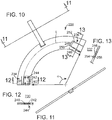
- FIGS. 10, 11, 12, and 13 illustrate various views for an example of the segments 202, 204, 206.
- FIG. 10 illustrates a plan view of the top of the example.
- FIG. 11 illustrates an elevation view of the cross-section of the example of FIG. 10 taken at line 11-11.
- FIGS. 12 and 13 illustrate an elevation view of the cross-section of the example of FIG. 10 taken at line 12-12 and line 13-13, respectively.
- the example has an arcuate body 228 that terminates at a pair of ends (e.g., a first end 230 and a second end 232).
- the arcuate body 228 can form a flat plate (as shown in FIG. 11 ), preferably made or comprised of metal and/or metal alloys.
- the shape of flat plate can form an arc with an arc length L as measured between the ends 230, 232. This arc can subtend an angle ⁇ . Values for the arc length L and/or the angle ⁇ may be approximately the same across all of the segments 202, 204, 206 ( FIGS. 7 , 8 , and 9 ).
- the angle ⁇ may assume values in a range of from approximately 60° to approximately 180°.
- the arc length L and/or angle ⁇ area may be individually configured so that the segments 202, 204, 206 will form the ring 132 ( FIG. 3 ) as noted herein.
- the arcuate body 228 can have one or more coupling features (e.g., a first coupling feature 234 and a second coupling feature 236).
- the coupling features 234, 236 configure the flat plate to receive (or host) the coupling members 208, 210, 212 ( FIG. 8 ) proximate the ends 230, 232.
- geometry from the coupling features 234, 236 allow sliding engagement of the coupling members 208, 210, 212 to prevent sticking that can frustrate operation of the valve 100. This geometry can vary, as desired.
- the first coupling feature 234 forms a first recess 238 that penetrates into the flat plate.
- the first recess 238 can have a bottom 240 and a peripheral side wall 242 that terminates at the end 230.
- One or more openings 244 may populate the first recess 238. As best shown in FIG. 13 , the openings 244 can penetrate through the flat plate in the first recess 238.
- the openings 244 may correspond with openings and/or fasteners (e.g., screws, bolts, etc.) found in the coupling members 208, 210, 212.
- the openings 244 can include threads and/or be sized to receive the fastener, as desired.
- the second coupling feature 236 may form a second recess 246 that penetrates into the flat plate.
- the second recess 246 has a first portion 248 and a second portion 250.
- a peripheral sidewall 252 bounds each of the portions 248, 250 and terminates at the end 232.
- the recess 244 includes a step 254 that forms a pair of bottom surfaces (e.g., a first bottom 256 and a second bottom 258) in the portions 248, 252, respectively.
- the bottoms 256, 258 are at different depths in the flat plate to accommodate geometry for the coupling members 208, 210, 212, as discussed more below.
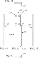
- FIGS. 14, 15, 16, 17, and 18 illustrate various views for an example of the coupling members 208, 210, 212.
- FIG. 14 is a plan view of the top of the example.
- FIGS. 15 and 16 depict elevation views of the sides of the example.
- FIGS. 17 and 18 depict elevation view of the front and back of the example, respectively.
- the example has a generally elongate, rectangular body 260 with a front 262, a back 264, and sides (e.g., a first side 266 and a second side 268).
- the body 260 can have one or more openings 270 that are arranged to correspond with the openings 244 ( FIG. 10 ) of the arcuate body 238 ( FIG. 10 ) discussed above.
- the body 260 can take the form of a flat plate.
- the flat plate On the first side 266, the flat plate can include a boss member 272, which may be a separate piece that secures to the flat plate.
- the boss member 272 may also be formed unilaterally or monolithically with the flat plate by machining these features from a block (or billet) of material. Suitable material may include metals and metal alloys, although other materials exhibit suitable material properties for use in the rectangular body 260.
- the boss member 272 can be sized to fit into the second portion 250 ( FIG. 10 ) of the second recess 246 ( FIGS. 10 and 13 ). In one implementation, the boss member 272 can extend from the back 264 toward the front 266, or vice versa.
- FIG. 19 illustrates a perspective view of the system 102 of FIG. 3 .
- the valve 100 has a construction similar to the example of the body member 200 of FIG. 8 .
- This example includes one or more bearing members (e.g., bearing member 142).
- the bearing members 142 can interpose between the segments 202, 204, 206 and a part of the system 102 and/or casing 104 ( FIG. 1 ), shown here as a blade carrier 144.
- the segments 202, 204, 206 may include a groove or other feature to receive at least part of the bearing member 142.
- the bearing members 142 can embody devices that reduce sliding friction that may frustrate movement of segments 202, 204, 204 relative to the blade carrier 144. These devices may include roller bearings, bearing slides, dovetail bearings, although any number of different kinds of bearings and bearing-like devices and materials might be applicable herein.
- FIG. 20 depicts a flow diagram of a method 300 for modulating flow across the rotor in a turbine.
- the method 300 includes, at stage 302, locating a ring member about the rotor in a flow pathway of the turbine and, at stage 304, partitioning the ring member into arcuate segments.
- the method 300 can also include, at stage 306, coupling adjacent segments to prevent flow through the ring member and, at stage 308, coupling an actuator individually to the segments.
- the method 300 further includes , at stage 310, allowing the segments to change position relative to one another and relative to the rotor to reduce an annular gap between the ring member and the rotor and, at stage 312, arranging the segments so that each has a first position and a second position that is closer to the rotor than the first position.
- the valve 100 can be disposed around the periphery of the rotor 114 to avoid interruption of rotation 122.
- steam F 1 flows through the fluid pathway 106 to impinge on the valve 100.
- steam F 3 can impinge on the rotor blades 120, causing the rotor 114 to turn and the turbine 100 to generate electricity.
- Movement of the actuators 214, 216, 218, preferably simultaneously or in concert, can change the position of segments 202, 204, 206 to set the size of the aperture 144 of the valve 100.
- the size of the aperture 144 can cause steam F 2 to exit the casing 104.
- the valve 100 may require service and maintenance to attend to parts in the system 102. Over time, these parts may experience wear and, possibly, damage that can frustrate operation of the valve 100. A technician may need to extract the valve 100, either in whole or in pieces, to remove existing parts in favor of one or more replacement parts. Examples of replacement parts may originate from an OEM or alternative aftermarket dealer and/or distributor. These examples may be newly constructed using any of the conventional manufacturing and machining techniques (including additive manufacturing and/or "3-D printing"). For certain techniques, a model file that comprises one or more instructions of executable code (on a storage medium and downloadable and/or executable) may be used to define the features of the part. These instructions may cause a machine (e.g., a lathe, milling machine, additive manufacturing machine, etc.) to perform certain functions to result in parts for use in the valve 100.
- a machine e.g., a lathe, milling machine, additive manufacturing machine, etc.
- one or more of the replacement parts of the valve 100 may be formed by existing parts. Certain parts may lend themselves to refurbishing an like processes to prepare the existing parts into condition and/or specification for use as the replacement part in the valve 100. Exemplary processes may include buffing, bead-blasting, welding, soldering, machining, and like practices that are useful to buildup and/or remove material from the part, as desired.
- the replacement parts may be assembled into the valve 100 as a wholly-constructed assembly.
- the replacement parts may embody individual parts (e.g., segments 202, 204, 206, actuators 214, 216, 218, coupling members 208, 210, 212), as well as combinations and compilations thereof, possibly in the form of one or more sub-assemblies.
- FIG. 21 illustrates an exemplary process 400 to manufacture an example of the components for the valve 100.
- the exemplary process may leverage additive manufacturing techniques, alone or in combination with one or more other types of subtractive manufacturing techniques.
- the process 400 can include, at stage 402, configuring an additive manufacturing machine with executable instructions that define a net shape.
- the net shape can embody the body of a component for the valve 100 including, for example, the segments 202, 204, 206 and the coupling members 208, 210, 212 described hereinabove.
- the process 400 can also include, at stage 404, growing the net shape and, where necessary, at stage 406, performing one or more post-growth processes on the net shape.
- Implementations of the process 400 can render embodiments of the components of the valve 100. These implementations may result in, for example, a support member to support a frame in a compressor made by the process of configuring an additive manufacturing machine with executable instructions that define a net shape, growing the net shape, and performing one or more post-growth processes on the net shape.
- the one or more post-growth processes comprises heat treating the net shape, and/or comprises deburring the net shape, and/or comprises machining the net shape, and/or comprises apply a surface finish to one or more surfaces of the net shape, and/or comprises removing material of the net shape using abrasives, and/or comprises inspecting the net shape to accumulate dimensional data and comparing the dimensional data to a default value.
Landscapes
- Engineering & Computer Science (AREA)
- Mechanical Engineering (AREA)
- General Engineering & Computer Science (AREA)
- Chemical & Material Sciences (AREA)
- Combustion & Propulsion (AREA)
- Control Of Turbines (AREA)
- Lift Valve (AREA)
Claims (13)
- Turbine (102), umfassend:ein Gehäuse (104), das einen Fluidpfad (106) definiert;einen Rotor (114), der in dem Fluidpfad (106) angeordnet ist; undein Ventil (100), das den Rotor (114) umgibt, wobei das Ventil (100) eine Öffnung (144) definiert, die einen Strömungsbereich bildet, durch den Fluid zwischen dem Ventil (100) und dem Rotor (114) strömen kann;dadurch gekennzeichnet, dass das Ventil (100) ein Körperelement (200) aufweist, das eine Vielzahl von bogenförmigen Segmenten (202, 204, 206) umfasst; undwobei jedes der Vielzahl von bogenförmigen Segmenten (202, 204, 206) angeordnet ist, um sich unabhängig relativ zueinander und zum Rotor (114) zu bewegen.
- Turbine (102) nach Anspruch 1, wobei das Ventil (100) so konfiguriert ist, dass es betätigt wird, um die Größe des Strömungsbereichs relativ zum Rotor (114) zu ändern.
- Turbine (102) nach Anspruch 1 oder Anspruch 2, wobei das Ventil (100) Schaufeln (120) vorgelagert angeordnet ist, die am Rotor (114) angeordnet sind.
- Turbine (102) nach einem der vorstehenden Ansprüche, wobei das Ventil (100) Schaufeln (128) vorgelagert angeordnet ist, die am Gehäuse (104) angeordnet sind.
- Turbine (102) nach einem der vorstehenden Ansprüche, ferner umfassend eine Vielzahl von Aktuatoren (214, 216, 218), von denen jeweils einer mit der Vielzahl von bogenförmigen Segmenten (202, 204, 206) gekoppelt ist.
- Turbine (102) nach einem der vorstehenden Ansprüche, wobei das Körperelement (200) eine Vielzahl von Kopplungselementen (208, 210, 212) umfasst, die sich zwischen benachbarten der Vielzahl von bogenförmigen Segmenten (202, 204, 206) erstrecken, und wobei die Vielzahl von Kopplungselementen (208, 210, 212) konfiguriert ist, um Kontinuität zwischen einer gegen die Strömungsrichtung weisenden Oberfläche an der Vielzahl von bogenförmigen Segmenten (202, 204, 206) bereitzustellen, um Fluidströmung durch das Körperelement (200) zu verhindern.
- Turbine (102) nach einem der vorstehenden Ansprüche, wobei die Vielzahl von bogenförmigen Segmenten (204, 206, 208) einen inneren Umfangsrand (140) aufweist, der einen Spalt (146) mit dem Rotor (114) bildet, und wobei die bogenförmigen Segmente (204, 206, 208) konfiguriert sind, um eine Position einzunehmen, in der der innere Umfangsrand (140) eine Schnittstelle mit dem Rotor (114) aufweist.
- Turbine (102) nach einem der vorstehenden Ansprüche, wobei
der Rotor (114) einen Körper (116) mit einem ersten Satz von Schaufeln (120) aufweist;
das Gehäuse (104) den Rotor (114) mindestens teilweise umgibt, wobei das Gehäuse (104) einen zweiten Satz von Schaufeln (128) benachbart zum ersten Satz von Schaufeln (120) aufweist; und
das Ventil (100) ein Ringelement (138) umfasst, das den Rotor (114) umgibt, wobei das Ringelement einen inneren Umfangsrand aufweist, der einen Spalt mit dem Rotor (114) definiert, wobei sich der Spalt ringförmig zwischen dem Ringelement und dem Rotor (114) erstreckt,
wobei das Ringelement (138) konfiguriert ist, um den Spalt von einem ersten Spalt in einen zweiten Spalt zu ändern, um die Strömung von Arbeitsfluid durch das Ringelement und zwischen dem Ringelement und dem Rotor zu variieren. - Turbine (102) nach Anspruch 8, wobei das Ringelement (138) ein erstes bogenförmiges Segment und ein zweites bogenförmiges Segment umfasst, die jeweils konfiguriert sind, um sich unabhängig voneinander zu bewegen, um den Spalt vom ersten Spalt in den zweiten Spalt zu ändern.
- Turbine (102) nach Anspruch 8 oder Anspruch 9, wobei der zweite Spalt das Ringelement so konfiguriert, dass es eine Strömung über den Rotor verhindert.
- Verfahren zum Modulieren der Strömung über den Rotor in der Turbine nach Anspruch 1, wobei das Verfahren umfasst:Anordnen eines Ringelements (138) um den Rotor (114) im Strömungspfad der Turbine (102);Unterteilen des Ringelements (138) in bogenförmige Segmente; undErmöglichen, dass die Segmente ihre Position relativ zueinander und relativ zum Rotor (114) ändern, um einen ringförmigen Spalt zwischen dem Ringelement (138) und dem Rotor (114) zu verringern.
- Verfahren nach Anspruch 11, ferner umfassend:
Koppeln benachbarter Segmente, um eine Strömung durch das Ringelement zu verhindern (138). - Verfahren nach Anspruch 11 oder 12, ferner umfassend:
individuelles Koppeln eines Aktuators mit den Segmenten.
Priority Applications (1)
| Application Number | Priority Date | Filing Date | Title |
|---|---|---|---|
| PL16775262T PL3359780T3 (pl) | 2015-10-06 | 2016-10-04 | Zawór turbiny parowej zawierający łukowe segmenty |
Applications Claiming Priority (3)
| Application Number | Priority Date | Filing Date | Title |
|---|---|---|---|
| US201562237623P | 2015-10-06 | 2015-10-06 | |
| US14/977,713 US10030544B2 (en) | 2015-10-06 | 2015-12-22 | Extracting steam from a turbine |
| PCT/EP2016/073652 WO2017060228A1 (en) | 2015-10-06 | 2016-10-04 | A steam turbine valve comprising arcuate segments |
Publications (2)
| Publication Number | Publication Date |
|---|---|
| EP3359780A1 EP3359780A1 (de) | 2018-08-15 |
| EP3359780B1 true EP3359780B1 (de) | 2021-05-19 |
Family
ID=58447532
Family Applications (1)
| Application Number | Title | Priority Date | Filing Date |
|---|---|---|---|
| EP16775262.5A Active EP3359780B1 (de) | 2015-10-06 | 2016-10-04 | Ein dampfturbinen ventil, welches kreisförmige segmente beinhaltet |
Country Status (6)
| Country | Link |
|---|---|
| US (2) | US10030544B2 (de) |
| EP (1) | EP3359780B1 (de) |
| JP (1) | JP6820327B2 (de) |
| BR (1) | BR112018006855B1 (de) |
| PL (1) | PL3359780T3 (de) |
| WO (1) | WO2017060228A1 (de) |
Family Cites Families (17)
| Publication number | Priority date | Publication date | Assignee | Title |
|---|---|---|---|---|
| DE1934171A1 (de) * | 1968-09-11 | 1970-09-10 | Bergmann Borsig Veb | Duesengruppenregelung,insbesondere fuer geregelte Dampfentnahme an Dampfturbinen |
| US3999787A (en) * | 1972-04-17 | 1976-12-28 | Fast Load Control Inc. | Method of effecting fast turbine valving for improvement of power system stability |
| US3966355A (en) | 1975-06-24 | 1976-06-29 | Westinghouse Electric Corporation | Steam turbine extraction system |
| US4380146A (en) * | 1977-01-12 | 1983-04-19 | Westinghouse Electric Corp. | System and method for accelerating and sequencing industrial gas turbine apparatus and gas turbine electric power plants preferably with a digital computer control system |
| DE4214775A1 (de) * | 1992-05-04 | 1993-11-11 | Abb Patent Gmbh | Dampfturbine mit einem Drehschieber |
| DE19620949A1 (de) * | 1996-05-24 | 1997-11-27 | Abb Patent Gmbh | Radialdrehschieber zur Steuerung des Dampfdurchsatzes bei einer Dampfturbine |
| FR2789470B1 (fr) * | 1999-02-08 | 2001-04-13 | Alstom | Dispositif integre de regulation de soutirage destine a equiper une turbine a vapeur |
| US6402465B1 (en) * | 2001-03-15 | 2002-06-11 | Dresser-Rand Company | Ring valve for turbine flow control |
| PL2014876T3 (pl) * | 2007-07-10 | 2012-11-30 | Siemens Ag | Suwak obrotowy do sterowania przepływem pary w turbinie parowej |
| DE102011108487A1 (de) | 2011-07-25 | 2013-01-31 | Metso Automation Mapag Gmbh | Regelklappe |
| US8925319B2 (en) * | 2012-08-17 | 2015-01-06 | General Electric Company | Steam flow control system |
| WO2014117074A1 (en) * | 2013-01-28 | 2014-07-31 | Echogen Power Systems, L.L.C. | Process for controlling a power turbine throttle valve during a supercritical carbon dioxide rankine cycle |
| US9739395B2 (en) | 2014-01-09 | 2017-08-22 | Dresser-Rand Company | Grid valve apparatus |
| US9334759B2 (en) | 2014-02-07 | 2016-05-10 | Dresser-Road Company | Grid valve assembly |
| US9926852B2 (en) * | 2015-03-03 | 2018-03-27 | General Electric Company | Methods and systems for enhancing control of power plant generating units |
| US9957900B2 (en) * | 2015-05-11 | 2018-05-01 | General Electric Company | System and method for flow control in turbine |
| US10648358B2 (en) * | 2016-12-15 | 2020-05-12 | Dresser-Rand Company | Systems and methods for protecting a turbomachine |
-
2015
- 2015-12-22 US US14/977,713 patent/US10030544B2/en active Active
-
2016
- 2016-10-04 BR BR112018006855-1A patent/BR112018006855B1/pt active IP Right Grant
- 2016-10-04 EP EP16775262.5A patent/EP3359780B1/de active Active
- 2016-10-04 JP JP2018517383A patent/JP6820327B2/ja not_active Expired - Fee Related
- 2016-10-04 WO PCT/EP2016/073652 patent/WO2017060228A1/en not_active Ceased
- 2016-10-04 PL PL16775262T patent/PL3359780T3/pl unknown
-
2018
- 2018-06-25 US US16/016,732 patent/US10641131B2/en active Active
Non-Patent Citations (1)
| Title |
|---|
| None * |
Also Published As
| Publication number | Publication date |
|---|---|
| JP6820327B2 (ja) | 2021-01-27 |
| US20170096913A1 (en) | 2017-04-06 |
| PL3359780T3 (pl) | 2021-12-20 |
| BR112018006855A2 (pt) | 2018-10-16 |
| JP2018534462A (ja) | 2018-11-22 |
| US10641131B2 (en) | 2020-05-05 |
| US20180298786A1 (en) | 2018-10-18 |
| WO2017060228A1 (en) | 2017-04-13 |
| EP3359780A1 (de) | 2018-08-15 |
| BR112018006855B1 (pt) | 2023-02-14 |
| US10030544B2 (en) | 2018-07-24 |
Similar Documents
| Publication | Publication Date | Title |
|---|---|---|
| RU2532868C2 (ru) | Направляющий аппарат турбины для газотурбинного двигателя, сектор направляющего аппарата, непрерывный кольцевой кронштейн, турбина низкого давления газотурбинного двигателя и газотурбинный двигатель | |
| RU2494264C2 (ru) | Разделенный на сектора направляющий аппарат для турбомашины, турбина низкого давления турбомашины и турбомашина | |
| EP3172410B1 (de) | Leitschaufelanordnung in einem gasturbinentriebwerk | |
| CN101067384A (zh) | 旋转机器及装配方法 | |
| EP3060758B1 (de) | Verfahren zur herstellung einer stufe einer dampfturbine | |
| EP2753799B1 (de) | Drahtnutreparatur in einer rotordichtung | |
| JP2013164068A (ja) | タービンアセンブリ | |
| CN102365425B (zh) | 密封板和动叶片系统 | |
| JP2018529877A (ja) | 回転する流れ供給システムのための流れ制御装置 | |
| CH709128A2 (de) | Dampfturbine und Verfahren zur Montage derselben. | |
| RU2743065C2 (ru) | Радиальный запирающий элемент для уплотнения ротора паровой турбины, соответствующий узел и паровая турбина | |
| US10641131B2 (en) | Extracting steam from a turbine | |
| US10927675B2 (en) | Method for maintaining a turbomachine | |
| EP2679777A1 (de) | Verdichter für eine Gasturbine und Verfahren zur Reparatur und/oder zum Ändern der Geometrie und/oder zur Wartung des Verdichters | |
| RU2762016C2 (ru) | Уплотнительное устройство между ротором и статором газотурбинного двигателя | |
| EP2660003A2 (de) | Verfahren zur Reparatur eines Bauteils einer Strömungsmaschine | |
| CN106194276A (zh) | 压缩机系统和翼型件组件 | |
| EP3112598B1 (de) | Dampfturbinendüsensegment zur partiellen bogenanwendung, entsprechende anordnung und dampfturbine | |
| US5056989A (en) | Stage replacement blade ring flow guide | |
| CN104564171A (zh) | 密封装置 | |
| US20130101386A1 (en) | Dual-flow steam turbine with steam cooling | |
| US20160333905A1 (en) | Modular system for forming an exiting flowpath in a fluid displacement device and implementation thereof | |
| EP2985412B2 (de) | Wartungsverfahren und kit für ein gasturbinenelektrizitätswerk | |
| US20140030083A1 (en) | Article of manufacture for turbomachine | |
| US9132528B2 (en) | Refurbishing system |
Legal Events
| Date | Code | Title | Description |
|---|---|---|---|
| STAA | Information on the status of an ep patent application or granted ep patent |
Free format text: STATUS: UNKNOWN |
|
| STAA | Information on the status of an ep patent application or granted ep patent |
Free format text: STATUS: THE INTERNATIONAL PUBLICATION HAS BEEN MADE |
|
| PUAI | Public reference made under article 153(3) epc to a published international application that has entered the european phase |
Free format text: ORIGINAL CODE: 0009012 |
|
| STAA | Information on the status of an ep patent application or granted ep patent |
Free format text: STATUS: REQUEST FOR EXAMINATION WAS MADE |
|
| 17P | Request for examination filed |
Effective date: 20180507 |
|
| AK | Designated contracting states |
Kind code of ref document: A1 Designated state(s): AL AT BE BG CH CY CZ DE DK EE ES FI FR GB GR HR HU IE IS IT LI LT LU LV MC MK MT NL NO PL PT RO RS SE SI SK SM TR |
|
| AX | Request for extension of the european patent |
Extension state: BA ME |
|
| DAV | Request for validation of the european patent (deleted) | ||
| DAX | Request for extension of the european patent (deleted) | ||
| STAA | Information on the status of an ep patent application or granted ep patent |
Free format text: STATUS: EXAMINATION IS IN PROGRESS |
|
| 17Q | First examination report despatched |
Effective date: 20200131 |
|
| GRAP | Despatch of communication of intention to grant a patent |
Free format text: ORIGINAL CODE: EPIDOSNIGR1 |
|
| STAA | Information on the status of an ep patent application or granted ep patent |
Free format text: STATUS: GRANT OF PATENT IS INTENDED |
|
| INTG | Intention to grant announced |
Effective date: 20201217 |
|
| GRAS | Grant fee paid |
Free format text: ORIGINAL CODE: EPIDOSNIGR3 |
|
| GRAA | (expected) grant |
Free format text: ORIGINAL CODE: 0009210 |
|
| STAA | Information on the status of an ep patent application or granted ep patent |
Free format text: STATUS: THE PATENT HAS BEEN GRANTED |
|
| AK | Designated contracting states |
Kind code of ref document: B1 Designated state(s): AL AT BE BG CH CY CZ DE DK EE ES FI FR GB GR HR HU IE IS IT LI LT LU LV MC MK MT NL NO PL PT RO RS SE SI SK SM TR |
|
| REG | Reference to a national code |
Ref country code: GB Ref legal event code: FG4D |
|
| REG | Reference to a national code |
Ref country code: CH Ref legal event code: EP |
|
| REG | Reference to a national code |
Ref country code: DE Ref legal event code: R096 Ref document number: 602016058098 Country of ref document: DE |
|
| REG | Reference to a national code |
Ref country code: AT Ref legal event code: REF Ref document number: 1394150 Country of ref document: AT Kind code of ref document: T Effective date: 20210615 |
|
| REG | Reference to a national code |
Ref country code: IE Ref legal event code: FG4D |
|
| REG | Reference to a national code |
Ref country code: LT Ref legal event code: MG9D |
|
| REG | Reference to a national code |
Ref country code: AT Ref legal event code: MK05 Ref document number: 1394150 Country of ref document: AT Kind code of ref document: T Effective date: 20210519 |
|
| REG | Reference to a national code |
Ref country code: NL Ref legal event code: MP Effective date: 20210519 |
|
| PG25 | Lapsed in a contracting state [announced via postgrant information from national office to epo] |
Ref country code: LT Free format text: LAPSE BECAUSE OF FAILURE TO SUBMIT A TRANSLATION OF THE DESCRIPTION OR TO PAY THE FEE WITHIN THE PRESCRIBED TIME-LIMIT Effective date: 20210519 Ref country code: FI Free format text: LAPSE BECAUSE OF FAILURE TO SUBMIT A TRANSLATION OF THE DESCRIPTION OR TO PAY THE FEE WITHIN THE PRESCRIBED TIME-LIMIT Effective date: 20210519 Ref country code: AT Free format text: LAPSE BECAUSE OF FAILURE TO SUBMIT A TRANSLATION OF THE DESCRIPTION OR TO PAY THE FEE WITHIN THE PRESCRIBED TIME-LIMIT Effective date: 20210519 Ref country code: BG Free format text: LAPSE BECAUSE OF FAILURE TO SUBMIT A TRANSLATION OF THE DESCRIPTION OR TO PAY THE FEE WITHIN THE PRESCRIBED TIME-LIMIT Effective date: 20210819 Ref country code: HR Free format text: LAPSE BECAUSE OF FAILURE TO SUBMIT A TRANSLATION OF THE DESCRIPTION OR TO PAY THE FEE WITHIN THE PRESCRIBED TIME-LIMIT Effective date: 20210519 |
|
| PG25 | Lapsed in a contracting state [announced via postgrant information from national office to epo] |
Ref country code: GR Free format text: LAPSE BECAUSE OF FAILURE TO SUBMIT A TRANSLATION OF THE DESCRIPTION OR TO PAY THE FEE WITHIN THE PRESCRIBED TIME-LIMIT Effective date: 20210820 Ref country code: LV Free format text: LAPSE BECAUSE OF FAILURE TO SUBMIT A TRANSLATION OF THE DESCRIPTION OR TO PAY THE FEE WITHIN THE PRESCRIBED TIME-LIMIT Effective date: 20210519 Ref country code: IS Free format text: LAPSE BECAUSE OF FAILURE TO SUBMIT A TRANSLATION OF THE DESCRIPTION OR TO PAY THE FEE WITHIN THE PRESCRIBED TIME-LIMIT Effective date: 20210919 Ref country code: PT Free format text: LAPSE BECAUSE OF FAILURE TO SUBMIT A TRANSLATION OF THE DESCRIPTION OR TO PAY THE FEE WITHIN THE PRESCRIBED TIME-LIMIT Effective date: 20210920 Ref country code: NO Free format text: LAPSE BECAUSE OF FAILURE TO SUBMIT A TRANSLATION OF THE DESCRIPTION OR TO PAY THE FEE WITHIN THE PRESCRIBED TIME-LIMIT Effective date: 20210819 Ref country code: RS Free format text: LAPSE BECAUSE OF FAILURE TO SUBMIT A TRANSLATION OF THE DESCRIPTION OR TO PAY THE FEE WITHIN THE PRESCRIBED TIME-LIMIT Effective date: 20210519 Ref country code: SE Free format text: LAPSE BECAUSE OF FAILURE TO SUBMIT A TRANSLATION OF THE DESCRIPTION OR TO PAY THE FEE WITHIN THE PRESCRIBED TIME-LIMIT Effective date: 20210519 |
|
| PG25 | Lapsed in a contracting state [announced via postgrant information from national office to epo] |
Ref country code: NL Free format text: LAPSE BECAUSE OF FAILURE TO SUBMIT A TRANSLATION OF THE DESCRIPTION OR TO PAY THE FEE WITHIN THE PRESCRIBED TIME-LIMIT Effective date: 20210519 |
|
| PG25 | Lapsed in a contracting state [announced via postgrant information from national office to epo] |
Ref country code: SM Free format text: LAPSE BECAUSE OF FAILURE TO SUBMIT A TRANSLATION OF THE DESCRIPTION OR TO PAY THE FEE WITHIN THE PRESCRIBED TIME-LIMIT Effective date: 20210519 Ref country code: SK Free format text: LAPSE BECAUSE OF FAILURE TO SUBMIT A TRANSLATION OF THE DESCRIPTION OR TO PAY THE FEE WITHIN THE PRESCRIBED TIME-LIMIT Effective date: 20210519 Ref country code: DK Free format text: LAPSE BECAUSE OF FAILURE TO SUBMIT A TRANSLATION OF THE DESCRIPTION OR TO PAY THE FEE WITHIN THE PRESCRIBED TIME-LIMIT Effective date: 20210519 Ref country code: EE Free format text: LAPSE BECAUSE OF FAILURE TO SUBMIT A TRANSLATION OF THE DESCRIPTION OR TO PAY THE FEE WITHIN THE PRESCRIBED TIME-LIMIT Effective date: 20210519 Ref country code: ES Free format text: LAPSE BECAUSE OF FAILURE TO SUBMIT A TRANSLATION OF THE DESCRIPTION OR TO PAY THE FEE WITHIN THE PRESCRIBED TIME-LIMIT Effective date: 20210519 Ref country code: RO Free format text: LAPSE BECAUSE OF FAILURE TO SUBMIT A TRANSLATION OF THE DESCRIPTION OR TO PAY THE FEE WITHIN THE PRESCRIBED TIME-LIMIT Effective date: 20210519 |
|
| REG | Reference to a national code |
Ref country code: DE Ref legal event code: R097 Ref document number: 602016058098 Country of ref document: DE |
|
| PLBE | No opposition filed within time limit |
Free format text: ORIGINAL CODE: 0009261 |
|
| STAA | Information on the status of an ep patent application or granted ep patent |
Free format text: STATUS: NO OPPOSITION FILED WITHIN TIME LIMIT |
|
| 26N | No opposition filed |
Effective date: 20220222 |
|
| REG | Reference to a national code |
Ref country code: CH Ref legal event code: PL |
|
| PG25 | Lapsed in a contracting state [announced via postgrant information from national office to epo] |
Ref country code: IS Free format text: LAPSE BECAUSE OF FAILURE TO SUBMIT A TRANSLATION OF THE DESCRIPTION OR TO PAY THE FEE WITHIN THE PRESCRIBED TIME-LIMIT Effective date: 20210919 Ref country code: AL Free format text: LAPSE BECAUSE OF FAILURE TO SUBMIT A TRANSLATION OF THE DESCRIPTION OR TO PAY THE FEE WITHIN THE PRESCRIBED TIME-LIMIT Effective date: 20210519 |
|
| REG | Reference to a national code |
Ref country code: BE Ref legal event code: MM Effective date: 20211031 |
|
| GBPC | Gb: european patent ceased through non-payment of renewal fee |
Effective date: 20211004 |
|
| PG25 | Lapsed in a contracting state [announced via postgrant information from national office to epo] |
Ref country code: MC Free format text: LAPSE BECAUSE OF FAILURE TO SUBMIT A TRANSLATION OF THE DESCRIPTION OR TO PAY THE FEE WITHIN THE PRESCRIBED TIME-LIMIT Effective date: 20210519 |
|
| PG25 | Lapsed in a contracting state [announced via postgrant information from national office to epo] |
Ref country code: LU Free format text: LAPSE BECAUSE OF NON-PAYMENT OF DUE FEES Effective date: 20211004 Ref country code: IT Free format text: LAPSE BECAUSE OF FAILURE TO SUBMIT A TRANSLATION OF THE DESCRIPTION OR TO PAY THE FEE WITHIN THE PRESCRIBED TIME-LIMIT Effective date: 20210519 Ref country code: GB Free format text: LAPSE BECAUSE OF NON-PAYMENT OF DUE FEES Effective date: 20211004 Ref country code: BE Free format text: LAPSE BECAUSE OF NON-PAYMENT OF DUE FEES Effective date: 20211031 |
|
| PG25 | Lapsed in a contracting state [announced via postgrant information from national office to epo] |
Ref country code: LI Free format text: LAPSE BECAUSE OF NON-PAYMENT OF DUE FEES Effective date: 20211031 Ref country code: CH Free format text: LAPSE BECAUSE OF NON-PAYMENT OF DUE FEES Effective date: 20211031 |
|
| PG25 | Lapsed in a contracting state [announced via postgrant information from national office to epo] |
Ref country code: FR Free format text: LAPSE BECAUSE OF NON-PAYMENT OF DUE FEES Effective date: 20211031 |
|
| PG25 | Lapsed in a contracting state [announced via postgrant information from national office to epo] |
Ref country code: IE Free format text: LAPSE BECAUSE OF NON-PAYMENT OF DUE FEES Effective date: 20211004 |
|
| PG25 | Lapsed in a contracting state [announced via postgrant information from national office to epo] |
Ref country code: HU Free format text: LAPSE BECAUSE OF FAILURE TO SUBMIT A TRANSLATION OF THE DESCRIPTION OR TO PAY THE FEE WITHIN THE PRESCRIBED TIME-LIMIT; INVALID AB INITIO Effective date: 20161004 |
|
| PG25 | Lapsed in a contracting state [announced via postgrant information from national office to epo] |
Ref country code: CY Free format text: LAPSE BECAUSE OF FAILURE TO SUBMIT A TRANSLATION OF THE DESCRIPTION OR TO PAY THE FEE WITHIN THE PRESCRIBED TIME-LIMIT Effective date: 20210519 |
|
| P01 | Opt-out of the competence of the unified patent court (upc) registered |
Effective date: 20230526 |
|
| PG25 | Lapsed in a contracting state [announced via postgrant information from national office to epo] |
Ref country code: MK Free format text: LAPSE BECAUSE OF FAILURE TO SUBMIT A TRANSLATION OF THE DESCRIPTION OR TO PAY THE FEE WITHIN THE PRESCRIBED TIME-LIMIT Effective date: 20210519 |
|
| PG25 | Lapsed in a contracting state [announced via postgrant information from national office to epo] |
Ref country code: TR Free format text: LAPSE BECAUSE OF FAILURE TO SUBMIT A TRANSLATION OF THE DESCRIPTION OR TO PAY THE FEE WITHIN THE PRESCRIBED TIME-LIMIT Effective date: 20210519 |
|
| PG25 | Lapsed in a contracting state [announced via postgrant information from national office to epo] |
Ref country code: MT Free format text: LAPSE BECAUSE OF FAILURE TO SUBMIT A TRANSLATION OF THE DESCRIPTION OR TO PAY THE FEE WITHIN THE PRESCRIBED TIME-LIMIT Effective date: 20210519 |
|
| PGFP | Annual fee paid to national office [announced via postgrant information from national office to epo] |
Ref country code: PL Payment date: 20250924 Year of fee payment: 10 |
|
| PGFP | Annual fee paid to national office [announced via postgrant information from national office to epo] |
Ref country code: CZ Payment date: 20250926 Year of fee payment: 10 |
|
| PGFP | Annual fee paid to national office [announced via postgrant information from national office to epo] |
Ref country code: DE Payment date: 20250923 Year of fee payment: 10 |