EP3359758B1 - Set of panels for floor, wall or ceiling covering - Google Patents
Set of panels for floor, wall or ceiling covering Download PDFInfo
- Publication number
- EP3359758B1 EP3359758B1 EP16778031.1A EP16778031A EP3359758B1 EP 3359758 B1 EP3359758 B1 EP 3359758B1 EP 16778031 A EP16778031 A EP 16778031A EP 3359758 B1 EP3359758 B1 EP 3359758B1
- Authority
- EP
- European Patent Office
- Prior art keywords
- panel
- toothed part
- locking profile
- panels
- profile
- Prior art date
- Legal status (The legal status is an assumption and is not a legal conclusion. Google has not performed a legal analysis and makes no representation as to the accuracy of the status listed.)
- Active
Links
Images

Classifications
-
- E—FIXED CONSTRUCTIONS
- E04—BUILDING
- E04F—FINISHING WORK ON BUILDINGS, e.g. STAIRS, FLOORS
- E04F15/00—Flooring
- E04F15/02—Flooring or floor layers composed of a number of similar elements
- E04F15/02038—Flooring or floor layers composed of a number of similar elements characterised by tongue and groove connections between neighbouring flooring elements
-
- E—FIXED CONSTRUCTIONS
- E04—BUILDING
- E04F—FINISHING WORK ON BUILDINGS, e.g. STAIRS, FLOORS
- E04F2201/00—Joining sheets or plates or panels
- E04F2201/03—Undercut connections, e.g. using undercut tongues or grooves
-
- E—FIXED CONSTRUCTIONS
- E04—BUILDING
- E04F—FINISHING WORK ON BUILDINGS, e.g. STAIRS, FLOORS
- E04F2201/00—Joining sheets or plates or panels
- E04F2201/05—Separate connectors or inserts, e.g. pegs, pins, keys or strips
- E04F2201/0523—Separate tongues; Interlocking keys, e.g. joining mouldings of circular, square or rectangular shape
- E04F2201/0535—Separate tongues; Interlocking keys, e.g. joining mouldings of circular, square or rectangular shape adapted for snap locking
-
- E—FIXED CONSTRUCTIONS
- E04—BUILDING
- E04F—FINISHING WORK ON BUILDINGS, e.g. STAIRS, FLOORS
- E04F2201/00—Joining sheets or plates or panels
- E04F2201/05—Separate connectors or inserts, e.g. pegs, pins, keys or strips
- E04F2201/0523—Separate tongues; Interlocking keys, e.g. joining mouldings of circular, square or rectangular shape
- E04F2201/0564—Separate tongues; Interlocking keys, e.g. joining mouldings of circular, square or rectangular shape depending on the use of specific materials
- E04F2201/0576—Separate tongues; Interlocking keys, e.g. joining mouldings of circular, square or rectangular shape depending on the use of specific materials of metal
-
- E—FIXED CONSTRUCTIONS
- E04—BUILDING
- E04F—FINISHING WORK ON BUILDINGS, e.g. STAIRS, FLOORS
- E04F2201/00—Joining sheets or plates or panels
- E04F2201/05—Separate connectors or inserts, e.g. pegs, pins, keys or strips
- E04F2201/0523—Separate tongues; Interlocking keys, e.g. joining mouldings of circular, square or rectangular shape
- E04F2201/0564—Separate tongues; Interlocking keys, e.g. joining mouldings of circular, square or rectangular shape depending on the use of specific materials
- E04F2201/0588—Separate tongues; Interlocking keys, e.g. joining mouldings of circular, square or rectangular shape depending on the use of specific materials of organic plastics with or without reinforcements or filling materials
Definitions
- the invention generally relates to the field of sets of panels for covering floors, ceilings or walls, in particular sets of panels comprising a plurality of panels to be joined at their adjacent edges.
- the disclosure aims at a set of panels for covering floors, ceilings or walls with a mechanical locking between adjacent panels.
- EP 2687650 , US2015/176289 , US2011/0271632 , US2007/006543 & WO2012007851 disclose a set of panels wherein each panel comprises a pair of retaining profiles that can cooperate to join the adjacent edges of two adjacent panels, whereby a separate locking profile is mounted on one of the retaining profiles to obtain both a vertical and horizontal locking.
- the separate locking profile is comprises a base and two upright portions, whereby the locking profile is mounted on one of the retaining profiles in a prestressed manner, whereby the base is bulged upward such that the two upright portions diverge from one another in the vertical direction, allowing an easy access to the second retaining profile.
- the second retaining profile presses the base of the locking profile downward such that the locking profile relaxes and the upright portions move inwardly, thereby locking two panels to one another.
- Such locking profile has the drawback that an accidental relaxation of the locking profile may occur during transport, rendering subsequent joining of panels cumbersome if not impossible.
- a set of panels according to the present invention comprises a plurality of panels each having a surface preferably with a decor visible when the panels are installed as a floor, wall or ceiling covering and further referred to herein as 'decor surface' (7), and an opposed surface (7', further referred to as ⁇ bottom surface') directed to a floor, wall or ceiling covered by the panels when installed.
- the panels can have any suitable shape, including rectangular, square or polygonal.
- Each of the panels comprises at least two pairs of parallel side edges, and in the case of rectangular panels, one pair of long side edges extending in the length direction of the panels and another pair of short side edges or transversal edges extending in a width direction of the panels.
- Locking is hereby to be understood as connected while preventing movement spacing the locked panels apart in a direction perpendicular to the coupled side edges by a translation (not tilting) in the plane of the bottom surface of the panels (horizontal locking in the event of a horizontal surface such as a floor) and while preventing movement spacing the locked panels apart in a direction perpendicular to the coupled side edges by a translation (not tilting) in a plane perpendicular to the bottom surface of the panels (vertical locking in the event of a horizontal surface such as a floor).
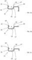
- the first retaining profile (3) shown in Figure 2a , comprises a first protruding member (8) having a top surface (11), the first protruding member (8) preferably extending at least substantially, and more preferably entirely, along the first side edge (2) and a first toothed part (9) disposed at a free end of the first protruding member (8) and having an upper surface (9b), the first toothed part (9) preferably equally extending along the first side edge (2).
- the first protruding member (8) extends in the height direction from the level H B of the bottom surface 7' to a level H PM1 of the top surface (11) of the first protruding member (8).
- the first toothed part (9) extends in the height direction from the level H B of the bottom surface 7' to a level H T1 of the upper surface (9b) of the first toothed part (9) between H PM1 and H TOP .
- the first retaining profile (3) defines a first channel (10) delimited by, on the one hand, the side edge (2) of the first panel and the toothed part (9) and on the other hand a top surface (11) of the first protruding member (8) extending between the side edge (2) and the first toothed part (9).
- the first retaining profile (3) further comprises a protruding rim (23) that extends from the first side edge (2) along the length of that side edge from a level H TOP of the decor surface (7) to a level H R between H TOP and the top surface (11) of the first protruding member (8) at level H PM1 , this protruding rim (23) as such partially extending above the first channel (10).
- the protruding rim (23) extends from the first side edge (2) along the length of that side edge from a level H TOP of the decor surface (7) to a level H R between H TOP and the upper surface (9b).
- a locking profile (15) is mounted to the first retaining profile (3), said locking profile (15) comprises: a base (16) that, in a mounted position, is seated in the first channel (10) along the top surface (11) of the first protruding member (8); a first abutment portion (17) extending along a surface (9a) of the first toothed part (9) defining an edge of the first channel (10); and a second abutment portion (19) located along the side edge (2) of the panel (1) delimiting the first channel (10), said second abutment portion (19) comprising a rim (22) at its free end and extending in a direction facing away from the side edge (2) of the first panel (1).
- the height of the second abutment portion is such that, in an assembled state of the panels, the free end of the second abutment portion (19) is situated against or substantially against a surface of the rim (23) facing the first channel (10).
- the first abutment portion (17) defines an abutment surface (18) facing away from the first toothed part (9), and hence facing the first channel (10).
- the abutment surface (18) of the first abutment portion (17) facing away from the first toothed part (9) is roughened. This would further increase the resistance of locked panels against moving apart.
- the locking profile (15) is attached to the first toothed part (9).
- the locking profile (15) comprises a shielding portion (20) extending from the first abutment portion (17) along an upper surface (9b) of the first toothed part (9) up to the edge of said upper surface (9b) at the free end of the toothed part (9).
- the shielding portion can further extend along the free end surface (9c) of the first toothed part (9).
- first toothed part by an adhesive, applied between the locking profile (15) and one or more of: a portion of a top surface (11) of the protruding member (8), the surface (9a) of the first toothed part (9) defining an edge of the channel (10); the upper surface (9b) of the first toothed part (9) and a surface (9c) of the first toothed part defining a free end of that first toothed part (9).
- the locking profile (15) is fixed to the first toothed part (9) by at least its shielding portion (20), and preferably also by the first abutment portion (17), that is immobilized with respect to the first toothed part (9) and that shields the first toothed part (9) from an accidental impact, thereby decreasing the probability that the first retaining profile (3) is damaged during transport or assembly of the set of panels. Additionally, the shielding of the first toothed part (9) decreases the risk of damaging the first toothed part (9) upon disassembly of the panels and increases the overall strength of the panels in a assembled state.
- the locking profile (15) extends along the first channel (10) and can have a length slightly smaller than the length of the concerned side edge (2) of the panel along which it extends or can have a length that is substantially shorter (eg. 2-5 cm) than the side edge (2), in which case it is preferred that several spaced apart locking profiles (15) are provided along the side edge (2).
- the locking profile(s) (15) mounted to the first retaining profile (3) as such define a slot for receiving part of the second retaining profile (6) of an adjacent panel (4) of the set of panels therein.
- the first abutment portion (17), and in particular the abutment surface (18), is oriented such as to define an angle ⁇ with the decor surface (7) of the first panel that is larger than 90° and smaller than 135°, preferably smaller than 125° and most preferably smaller than 120°.
- the angle ⁇ of the retaining profile along at least one edge is chosen between 99° and 106°, whilst the angle ⁇ of the retaining profile along another edge (long edge) is preferably larger than 106° allowing more easy disassembly of the panels locked along that side edge by angling.
- the first abutment portion (17) may be partially curved.
- the locking profile (15) is preferably manufactured in one piece and can be made in a metallic material such as aluminum or spring steel; or in a polymeric material, preferably a fibre reinforced polymeric material.
- the second retaining profile (6) is disposed at the second side edge (5) of the panel opposed to the first side edge (2) where the first retaining profile (3) is disposed.
- this second retaining profile (6) comprises a second protruding member (13) extending along the second side edge (5) and a second toothed part (14) disposed at a free end of the second protruding member (13) and equally extending along the second side edge (5).
- the second protruding member (13) extends in the height direction from a level H TOP corresponding to the level at which the top surface (7) of the panel (2) extends to a level H PM2 of the lower surface (27) of the second protruding member (13), between H TOP and H T1 .
- the second toothed part (14) extends in the height direction from the level H TOP to a level H T2 of the lower surface (28) of the second toothed part (14), between H PM1 and H TOP .
- the second retaining profile (6) defines a second channel (24) delimited by, on the one hand, the side edge (5) of the second panel (4) and the second toothed part (14) and on the other hand a lower surface (27) of the second protruding member (13) extending between the second side edge (5) and the second toothed part (14).
- the second toothed part (14) further comprises a groove (21) in a surface of the second toothed part (14) facing away from the side edge (5) of the second panel (4).
- the decor surfaces (7) of two adjacent panels extend in a same plane at a level H TOP .
- the dimensions of the second toothed part (14) are such that - when two panels are locked - the second toothed part (14) of the second panel (4), on the one hand abuts the first abutment portion (17) of the locking profile (15) on the first panel (1) and, on the other hand abuts the protruding rim (23) of the first panel, thereby effectively preventing (however allowing some play within the standards well known to the Person skilled in the art) a translation of the second panel (4) in view of the first panel (1) in the plane of the bottom surfaces (7') of both panels (1, 4) and in a direction perpendicular to the cooperating side edges (2, 5) of both adjacent panels (1, 4) (horizontal locking).
- the second toothed part (14) of the second panel is dimensioned such that, in the assembled state, it abuts the base (16) on the locking profile (15) of the first panel (1), while the rim (22) of that locking profile (15) snaps into the groove (21) of the second toothed part (14), whereby the locking profile (15) is prevented from moving out of the first channel (10) as the second abutment portion (19) abuts the rim (23) of the first panel (1).
- both panels (1, 4) are locked from moving in a direction perpendicular to the decor surface (7) (vertical lock).
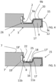
- Figures 3a & 4 illustrate another preferred embodiment of the present invention, wherein the locking profile (15) is attached to the first toothed part (9) by clamping rather than by an adhesive.
- a groove or undercut (12) is provided in a surface (9c) of the first toothed part (9) defining the free end of the first toothed part (9) facing away the first side edge (2) of the corresponding panel (1)
- the locking profile (15) comprises a shielding/clamping portion (20) extending from the first abutment portion (17) along an upper surface (9b) of the first toothed part (9) and further along the free end surface (9c) of the first toothed part (9) into the groove or undercut (12).
- the first toothed part (9) is shielded by the locking profile (15) from an accidental impact, thereby decreasing the probability that the first retaining profile (3) is damaged during transport or assembly or disassembly of the set of panels.
- the shielding portion (20), and preferably also the first abutment portion (17) is immobilized in view of the first toothed part (9), whilst the remainder of the locking profile (15) is allowed to move in view of the first retaining profile (3) allowing interaction with the second toothed part (14) of a second panel (4) to locking two panels (1, 4).
- the first channel (10) and the locking profile (15) are configured such as to establish a pivot (25), further referred to as the first pivot, positioned along the base (16) of the locking profile.
- a pivot 25
- Such pivot allows broadening the aperture of the slot - ie the distance between the free ends (17', 19') of the first and second abutment portions (17, 19) of the locking profile - upon exerting a pressure on the second abutment portion (19) in a direction normal to the bottom surface (7') of the first panel (1) and in a direction from the decor surface (7) of the panels towards the bottom surface (7') of said panels.
- the pivot is obtained by making the surface (1 1) of the first protruding member (8) facing the base (16) of the locking profile (15) such that it comprises a support section (11a) extending such that upon joining two adjacent profiles, the locking profile (15) is clamped between the support section (11a) and the second toothed part (14); and a second section (11b) positioned such that a void remains present between that section (11b) of the surface (11) and the second locking profile (15) when in a non-tensed position.
- a free space is maintained between the first side edge (2) of the first panel (1) and the second abutment portion (19) of the locking profile (15) such that in case the second abutment portion (19) is pushed towards the bottom surface of the panel, the base (16) partially pivots downward and the free ends of the first and second abutment portions are spaced further apart and favoring a movement of the free end of the second abutment portion (19) towards the side edge (2) of the first panel (1) under protruding rim (23).
- the locking profile (15) comprises a pivot (26) (further referred to as second pivot although it can be provided in addition to or as alternative for the above described pivot (25), positioned at the transition of the base (16) and the second abutment portion (19) or along the second abutment portion (19), which pivot allows the second abutment portion (19) to partially tilt such that its free end is spaced further apart from the first abutment portion (17) upon exerting a pressure on the free end of the second abutment portion (19).
- a pivot (26) further referred to as second pivot although it can be provided in addition to or as alternative for the above described pivot (25)
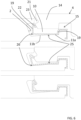
- figure 6 schematically illustrates the functioning of the pivot, whereby during assembly the second toothed part (14) of the second panel (4) is inserted in the first channel (10), whereby the bottom surface of the second toothed part (14) contacts the rim (22) of the locking profile (15), pressing the rim (22) down- and sidewards.
- the locking profile (15) pivots at first pivot (25) thereby tilting the second abutment portion (19) and rim (22) towards the side edge (2) of the first panel (in a direction under rim (23)) and as such increasing the distance between the free ends of the abutment portions (17, 19) of the locking profile.
- This distance between the abutment portions (17, 19) is further increased by the tilting of the second abutment portion (19) in view of the base (16) of the locking profile at the second pivot (26).
- the increasing distance allows the second toothed part (14) to move further in the channel (10) until the bottom surface of the second toothed part (14) contacts the base of the locking profile (15) at least at the position corresponding to the support section (11a) of the base of the channel (10).
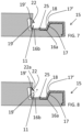
- the pivot (25) is obtained by a variation in the thickness of the locking profile along its base (16), such that this base (16) comprises a relatively thick and rigid portion (16a) and a relative thin and more flexible portion (16b).
- this alternative is similar to the functioning of the alternative depicted in figures 5 and 6 .
- the rim (22) is compressible or made by bending over the free edge (19') of the second abutment portion (19) of the locking profile (15), whereby the bending point (22a) or section acts as a pivot between the rim (22) and the remainder of the second abutment portion (19).
- the locking profile (15), the first channel (10) and the second toothed part (14) of two adjacent panels are preferably configured such as to allow introduction of the second toothed part (14) in the channel (10) up to a point wherein both panels are locked, by a pure translation of both panels in view of one another, ie in case the panels form a flooring, a movement of the second panel (4) in view of the first panel (1), without tilting one of both panels.
- Such configuration is particularly feasible when the retaining profiles are provided at the short edges of the panels.
- the locking profile (15), the first channel (10) and the second toothed part (14) of two adjacent panels are preferably configured such as to allow the introduction of the second toothed part (14) in the slot up to a point wherein both panels are locked and to allow releasing one panel from another to which it is locked, by a combination of tilting (angling) and translation of both panels in view of one another.
- the panels may be wood-based (e.g. a fiberboard (MDF, HDF), or a particle board).
- the panels may also be made of, or at least comprising a layer of, synthetic material.
- synthetic material as used in the context of the current invention, can be a single polymer or a blend of two or more polymers.
- the synthetic material can be, for example, a thermoplastic polymer, a thermosetting polymer, a rubber (elastomer), or any combinations thereof.
- the polymeric material is a thermoplastic polymer that includes vinyl containing thermoplastics such as polyvinyl chloride, polyvinyl acetate, polyvinyl alcohol, and other vinyl and vinylidene resins and copolymers thereof; polyethylenes such as low density polyethylenes and high density polyethylenes and copolymers thereof; styrenes such as ABS, SAN, and polystyrenes and copolymers thereof, polypropylene and copolymers thereof; saturated and unsaturated polyesters; acrylics; polyamides such as nylon containing types; engineering plastics such as polycarbonate, polyimide, polysulfone, and polyphenylene oxide and sulfide resins and the like.
- the synthetic material compound used to form the panel or a layer thereof can be a PVC powder compound that has good impact strength, ease of processing, high extrusion rate, good surface properties, excellent dimensional stability, and indentation resistance.
- the panels may also comprise composite materials, or one or more layers thereof, such as wood-plastic composites (WPC), referring to a composite structure comprising a wood-based material and a synthetic material.
- WPC wood-plastic composites
- the panel may comprise multiple layers which can be identical or different with respect to composition and/or physical properties.
- the panel may comprise a core, which can be single or multilayered, made from the materials described hereinbefore, and a top layer which may comprise a print layer and a wear layer.
- the panel may comprise a core, which can be single or multilayered, made from the materials described hereinbefore, onto which a decor is digitally printed, the decor further being covered by a wear layer.
Landscapes
- Engineering & Computer Science (AREA)
- Architecture (AREA)
- Civil Engineering (AREA)
- Structural Engineering (AREA)
- Finishing Walls (AREA)
- Floor Finish (AREA)
Priority Applications (1)
| Application Number | Priority Date | Filing Date | Title |
|---|---|---|---|
| EP24206163.8A EP4481135A3 (en) | 2015-10-08 | 2016-10-07 | Set of panels for floor, wall or ceiling covering |
Applications Claiming Priority (2)
| Application Number | Priority Date | Filing Date | Title |
|---|---|---|---|
| EP15189039 | 2015-10-08 | ||
| PCT/EP2016/073988 WO2017060419A1 (en) | 2015-10-08 | 2016-10-07 | Set of panels for floor, wall or ceiling covering |
Related Child Applications (2)
| Application Number | Title | Priority Date | Filing Date |
|---|---|---|---|
| EP24206163.8A Division EP4481135A3 (en) | 2015-10-08 | 2016-10-07 | Set of panels for floor, wall or ceiling covering |
| EP24206163.8A Division-Into EP4481135A3 (en) | 2015-10-08 | 2016-10-07 | Set of panels for floor, wall or ceiling covering |
Publications (3)
| Publication Number | Publication Date |
|---|---|
| EP3359758A1 EP3359758A1 (en) | 2018-08-15 |
| EP3359758B1 true EP3359758B1 (en) | 2024-11-20 |
| EP3359758C0 EP3359758C0 (en) | 2024-11-20 |
Family
ID=54291164
Family Applications (2)
| Application Number | Title | Priority Date | Filing Date |
|---|---|---|---|
| EP16778031.1A Active EP3359758B1 (en) | 2015-10-08 | 2016-10-07 | Set of panels for floor, wall or ceiling covering |
| EP24206163.8A Pending EP4481135A3 (en) | 2015-10-08 | 2016-10-07 | Set of panels for floor, wall or ceiling covering |
Family Applications After (1)
| Application Number | Title | Priority Date | Filing Date |
|---|---|---|---|
| EP24206163.8A Pending EP4481135A3 (en) | 2015-10-08 | 2016-10-07 | Set of panels for floor, wall or ceiling covering |
Country Status (9)
| Country | Link |
|---|---|
| US (2) | US10422143B2 (OSRAM) |
| EP (2) | EP3359758B1 (OSRAM) |
| JP (1) | JP2018534456A (OSRAM) |
| CN (1) | CN108368703A (OSRAM) |
| CA (1) | CA3001180C (OSRAM) |
| ES (1) | ES2997361T3 (OSRAM) |
| PL (1) | PL3359758T3 (OSRAM) |
| RU (1) | RU2730138C2 (OSRAM) |
| WO (1) | WO2017060419A1 (OSRAM) |
Families Citing this family (4)
| Publication number | Priority date | Publication date | Assignee | Title |
|---|---|---|---|---|
| US10422143B2 (en) * | 2015-10-08 | 2019-09-24 | Berryalloc Nv | Set of panels for floor, wall or ceiling covering |
| SE1851615A1 (en) | 2018-11-09 | 2020-05-10 | Ikea Supply Ag | Room divider system |
| WO2020094837A2 (en) * | 2018-11-09 | 2020-05-14 | Ikea Supply Ag | A room divider panel |
| DE102019134858A1 (de) * | 2019-12-18 | 2021-06-24 | Windmöller Gmbh | Fußbodenpaneel mit separatem Clip für die vertikale Verriegelung |
Family Cites Families (18)
| Publication number | Priority date | Publication date | Assignee | Title |
|---|---|---|---|---|
| SE529076C2 (sv) * | 2005-07-11 | 2007-04-24 | Pergo Europ Ab | En fog till paneler |
| BE1017157A3 (nl) * | 2006-06-02 | 2008-03-04 | Flooring Ind Ltd | Vloerbekleding, vloerelement en werkwijze voor het vervaardigen van vloerelementen. |
| DE102006057491A1 (de) * | 2006-12-06 | 2008-06-12 | Akzenta Paneele + Profile Gmbh | Paneel sowie Bodenbelag |
| DE202007018662U1 (de) * | 2007-03-26 | 2009-02-19 | Kronotec Ag | Paneel, insbesondere Bodenpaneel |
| BE1018600A5 (nl) * | 2007-11-23 | 2011-04-05 | Flooring Ind Ltd Sarl | Vloerpaneel. |
| BE1018627A5 (nl) * | 2009-01-16 | 2011-05-03 | Flooring Ind Ltd Sarl | Vloerpaneel. |
| DE102010004717A1 (de) * | 2010-01-15 | 2011-07-21 | Pergo (Europe) Ab | Set aus Paneelen umfassend Halteprofile mit einem separaten Clip sowie Verfahren zum Einbringen des Clips |
| BE1019747A3 (nl) * | 2010-07-15 | 2012-12-04 | Flooring Ind Ltd Sarl | Bekleding, alsmede panelen en hulpstukken daarbij aangewend. |
| US9725912B2 (en) * | 2011-07-11 | 2017-08-08 | Ceraloc Innovation Ab | Mechanical locking system for floor panels |
| DE202011108752U1 (de) * | 2011-12-06 | 2012-01-24 | Akzenta Paneele + Profile Gmbh | Verriegelungssystem für Paneelen und Paneel mit Verriegelungssystem |
| EP2687650B1 (de) | 2012-07-19 | 2017-12-13 | Barlinek S.A. | Baupaneel mit einer Einrichtung zur Verbindung mit wenigstens einem weiteren Baupaneel auf einem Untergrund |
| JP6313778B2 (ja) * | 2012-11-22 | 2018-04-18 | セラロック、イノベーション、アクチボラグ | フロアパネルの機械的固定システム |
| DE102013113109A1 (de) * | 2013-11-27 | 2015-06-11 | Guido Schulte | Fußbodendiele |
| DE202014010455U1 (de) * | 2014-09-30 | 2015-08-03 | Akzenta Paneele + Profile Gmbh | Paneel |
| US20160288447A1 (en) * | 2015-01-05 | 2016-10-06 | Eurico Januario Cordeiro | Waterproof composite core |
| US20180179763A1 (en) * | 2015-07-06 | 2018-06-28 | Tarkett Gdl | Chiral flexible rectangular floor covering element |
| US10422143B2 (en) * | 2015-10-08 | 2019-09-24 | Berryalloc Nv | Set of panels for floor, wall or ceiling covering |
| BE1023542B1 (nl) * | 2015-10-27 | 2017-04-28 | Unilin Bvba | Vloerpaneel en werkwijze voor het vervaardigen van vloerpanelen |
-
2016
- 2016-10-07 US US15/766,359 patent/US10422143B2/en active Active
- 2016-10-07 CA CA3001180A patent/CA3001180C/en active Active
- 2016-10-07 JP JP2018537720A patent/JP2018534456A/ja active Pending
- 2016-10-07 RU RU2018115085A patent/RU2730138C2/ru active
- 2016-10-07 EP EP16778031.1A patent/EP3359758B1/en active Active
- 2016-10-07 ES ES16778031T patent/ES2997361T3/es active Active
- 2016-10-07 PL PL16778031.1T patent/PL3359758T3/pl unknown
- 2016-10-07 WO PCT/EP2016/073988 patent/WO2017060419A1/en not_active Ceased
- 2016-10-07 EP EP24206163.8A patent/EP4481135A3/en active Pending
- 2016-10-07 CN CN201680058378.4A patent/CN108368703A/zh active Pending
-
2019
- 2019-09-23 US US16/579,735 patent/US10876302B2/en active Active
Also Published As
| Publication number | Publication date |
|---|---|
| US10876302B2 (en) | 2020-12-29 |
| EP3359758A1 (en) | 2018-08-15 |
| EP4481135A2 (en) | 2024-12-25 |
| US20180298618A1 (en) | 2018-10-18 |
| CN108368703A (zh) | 2018-08-03 |
| WO2017060419A1 (en) | 2017-04-13 |
| EP4481135A3 (en) | 2025-01-01 |
| EP3359758C0 (en) | 2024-11-20 |
| RU2018115085A (ru) | 2019-11-11 |
| CA3001180A1 (en) | 2017-04-13 |
| US10422143B2 (en) | 2019-09-24 |
| ES2997361T3 (en) | 2025-02-17 |
| CA3001180C (en) | 2023-10-31 |
| PL3359758T3 (pl) | 2025-02-24 |
| JP2018534456A (ja) | 2018-11-22 |
| US20200157821A1 (en) | 2020-05-21 |
| RU2730138C2 (ru) | 2020-08-19 |
| RU2018115085A3 (OSRAM) | 2020-03-12 |
Similar Documents
| Publication | Publication Date | Title |
|---|---|---|
| KR102740022B1 (ko) | 수직으로 잠금해제될 수 있는 패널들의 세트, 이의 방법 및 디바이스 | |
| US10876302B2 (en) | Set of panels for floor, wall or ceiling covering | |
| US20230258003A1 (en) | Panel with locking device | |
| KR102386246B1 (ko) | 기계식 록킹 시스템이 구비된 빌딩 패널 | |
| US12326001B2 (en) | Panel with locking device | |
| US10697187B2 (en) | Mechanical locking system for floor panels | |
| US10670064B2 (en) | Panel with a slider | |
| EP2440724B1 (en) | Floor panel and floor covering consisting of a plurality of such floor panels | |
| EP4041965B1 (en) | Floor panel for forming a floor covering | |
| CN107027318A (zh) | 具有滑动件的面板 | |
| EP2812510B1 (en) | Floor panel for forming a floor covering, floor covering formed from such floor panels and method for manufacturing such floor panels | |
| CA3010903C (en) | Set of panels, method for manufacturing such set of panels, assembly of the panels and locking profile used in said panels | |
| CN211396461U (zh) | 一种设置有机械锁定系统的塑胶地板 |
Legal Events
| Date | Code | Title | Description |
|---|---|---|---|
| STAA | Information on the status of an ep patent application or granted ep patent |
Free format text: STATUS: UNKNOWN |
|
| STAA | Information on the status of an ep patent application or granted ep patent |
Free format text: STATUS: THE INTERNATIONAL PUBLICATION HAS BEEN MADE |
|
| PUAI | Public reference made under article 153(3) epc to a published international application that has entered the european phase |
Free format text: ORIGINAL CODE: 0009012 |
|
| STAA | Information on the status of an ep patent application or granted ep patent |
Free format text: STATUS: REQUEST FOR EXAMINATION WAS MADE |
|
| 17P | Request for examination filed |
Effective date: 20180508 |
|
| AK | Designated contracting states |
Kind code of ref document: A1 Designated state(s): AL AT BE BG CH CY CZ DE DK EE ES FI FR GB GR HR HU IE IS IT LI LT LU LV MC MK MT NL NO PL PT RO RS SE SI SK SM TR |
|
| AX | Request for extension of the european patent |
Extension state: BA ME |
|
| DAV | Request for validation of the european patent (deleted) | ||
| DAX | Request for extension of the european patent (deleted) | ||
| STAA | Information on the status of an ep patent application or granted ep patent |
Free format text: STATUS: EXAMINATION IS IN PROGRESS |
|
| 17Q | First examination report despatched |
Effective date: 20190507 |
|
| GRAP | Despatch of communication of intention to grant a patent |
Free format text: ORIGINAL CODE: EPIDOSNIGR1 |
|
| STAA | Information on the status of an ep patent application or granted ep patent |
Free format text: STATUS: GRANT OF PATENT IS INTENDED |
|
| INTG | Intention to grant announced |
Effective date: 20240620 |
|
| GRAS | Grant fee paid |
Free format text: ORIGINAL CODE: EPIDOSNIGR3 |
|
| GRAA | (expected) grant |
Free format text: ORIGINAL CODE: 0009210 |
|
| STAA | Information on the status of an ep patent application or granted ep patent |
Free format text: STATUS: THE PATENT HAS BEEN GRANTED |
|
| AK | Designated contracting states |
Kind code of ref document: B1 Designated state(s): AL AT BE BG CH CY CZ DE DK EE ES FI FR GB GR HR HU IE IS IT LI LT LU LV MC MK MT NL NO PL PT RO RS SE SI SK SM TR |
|
| REG | Reference to a national code |
Ref country code: GB Ref legal event code: FG4D |
|
| REG | Reference to a national code |
Ref country code: CH Ref legal event code: EP |
|
| REG | Reference to a national code |
Ref country code: DE Ref legal event code: R096 Ref document number: 602016090314 Country of ref document: DE |
|
| REG | Reference to a national code |
Ref country code: IE Ref legal event code: FG4D |
|
| U01 | Request for unitary effect filed |
Effective date: 20241210 |
|
| U07 | Unitary effect registered |
Designated state(s): AT BE BG DE DK EE FI FR IT LT LU LV MT NL PT RO SE SI Effective date: 20241219 |
|
| REG | Reference to a national code |
Ref country code: ES Ref legal event code: FG2A Ref document number: 2997361 Country of ref document: ES Kind code of ref document: T3 Effective date: 20250217 |
|
| PG25 | Lapsed in a contracting state [announced via postgrant information from national office to epo] |
Ref country code: HR Free format text: LAPSE BECAUSE OF FAILURE TO SUBMIT A TRANSLATION OF THE DESCRIPTION OR TO PAY THE FEE WITHIN THE PRESCRIBED TIME-LIMIT Effective date: 20241120 Ref country code: IS Free format text: LAPSE BECAUSE OF FAILURE TO SUBMIT A TRANSLATION OF THE DESCRIPTION OR TO PAY THE FEE WITHIN THE PRESCRIBED TIME-LIMIT Effective date: 20250320 |
|
| PG25 | Lapsed in a contracting state [announced via postgrant information from national office to epo] |
Ref country code: GR Free format text: LAPSE BECAUSE OF FAILURE TO SUBMIT A TRANSLATION OF THE DESCRIPTION OR TO PAY THE FEE WITHIN THE PRESCRIBED TIME-LIMIT Effective date: 20250221 |
|
| PG25 | Lapsed in a contracting state [announced via postgrant information from national office to epo] |
Ref country code: RS Free format text: LAPSE BECAUSE OF FAILURE TO SUBMIT A TRANSLATION OF THE DESCRIPTION OR TO PAY THE FEE WITHIN THE PRESCRIBED TIME-LIMIT Effective date: 20250220 |
|
| PG25 | Lapsed in a contracting state [announced via postgrant information from national office to epo] |
Ref country code: SM Free format text: LAPSE BECAUSE OF FAILURE TO SUBMIT A TRANSLATION OF THE DESCRIPTION OR TO PAY THE FEE WITHIN THE PRESCRIBED TIME-LIMIT Effective date: 20241120 |
|
| PG25 | Lapsed in a contracting state [announced via postgrant information from national office to epo] |
Ref country code: SK Free format text: LAPSE BECAUSE OF FAILURE TO SUBMIT A TRANSLATION OF THE DESCRIPTION OR TO PAY THE FEE WITHIN THE PRESCRIBED TIME-LIMIT Effective date: 20241120 |
|
| PG25 | Lapsed in a contracting state [announced via postgrant information from national office to epo] |
Ref country code: CZ Free format text: LAPSE BECAUSE OF FAILURE TO SUBMIT A TRANSLATION OF THE DESCRIPTION OR TO PAY THE FEE WITHIN THE PRESCRIBED TIME-LIMIT Effective date: 20241120 |
|
| PLBE | No opposition filed within time limit |
Free format text: ORIGINAL CODE: 0009261 |
|
| STAA | Information on the status of an ep patent application or granted ep patent |
Free format text: STATUS: NO OPPOSITION FILED WITHIN TIME LIMIT |
|
| PGFP | Annual fee paid to national office [announced via postgrant information from national office to epo] |
Ref country code: PL Payment date: 20250918 Year of fee payment: 10 Ref country code: TR Payment date: 20250925 Year of fee payment: 10 |
|
| 26N | No opposition filed |
Effective date: 20250821 |
|
| U20 | Renewal fee for the european patent with unitary effect paid |
Year of fee payment: 10 Effective date: 20251027 |
|
| PGFP | Annual fee paid to national office [announced via postgrant information from national office to epo] |
Ref country code: GB Payment date: 20251027 Year of fee payment: 10 |
|
| PGFP | Annual fee paid to national office [announced via postgrant information from national office to epo] |
Ref country code: NO Payment date: 20251029 Year of fee payment: 10 |
|
| PGFP | Annual fee paid to national office [announced via postgrant information from national office to epo] |
Ref country code: ES Payment date: 20251103 Year of fee payment: 10 |