EP3358715B1 - Stator, motor, and pump device - Google Patents
Stator, motor, and pump device Download PDFInfo
- Publication number
- EP3358715B1 EP3358715B1 EP16851609.4A EP16851609A EP3358715B1 EP 3358715 B1 EP3358715 B1 EP 3358715B1 EP 16851609 A EP16851609 A EP 16851609A EP 3358715 B1 EP3358715 B1 EP 3358715B1
- Authority
- EP
- European Patent Office
- Prior art keywords
- outer peripheral
- stator
- parts
- curved face
- face
- Prior art date
- Legal status (The legal status is an assumption and is not a legal conclusion. Google has not performed a legal analysis and makes no representation as to the accuracy of the status listed.)
- Active
Links
Images


Classifications
-
- H—ELECTRICITY
- H02—GENERATION; CONVERSION OR DISTRIBUTION OF ELECTRIC POWER
- H02K—DYNAMO-ELECTRIC MACHINES
- H02K1/00—Details of the magnetic circuit
- H02K1/06—Details of the magnetic circuit characterised by the shape, form or construction
- H02K1/12—Stationary parts of the magnetic circuit
- H02K1/14—Stator cores with salient poles
- H02K1/146—Stator cores with salient poles consisting of a generally annular yoke with salient poles
- H02K1/148—Sectional cores
-
- H—ELECTRICITY
- H02—GENERATION; CONVERSION OR DISTRIBUTION OF ELECTRIC POWER
- H02K—DYNAMO-ELECTRIC MACHINES
- H02K1/00—Details of the magnetic circuit
- H02K1/06—Details of the magnetic circuit characterised by the shape, form or construction
- H02K1/12—Stationary parts of the magnetic circuit
- H02K1/14—Stator cores with salient poles
-
- F—MECHANICAL ENGINEERING; LIGHTING; HEATING; WEAPONS; BLASTING
- F04—POSITIVE - DISPLACEMENT MACHINES FOR LIQUIDS; PUMPS FOR LIQUIDS OR ELASTIC FLUIDS
- F04D—NON-POSITIVE-DISPLACEMENT PUMPS
- F04D13/00—Pumping installations or systems
- F04D13/02—Units comprising pumps and their driving means
- F04D13/06—Units comprising pumps and their driving means the pump being electrically driven
-
- H—ELECTRICITY
- H02—GENERATION; CONVERSION OR DISTRIBUTION OF ELECTRIC POWER
- H02K—DYNAMO-ELECTRIC MACHINES
- H02K1/00—Details of the magnetic circuit
- H02K1/06—Details of the magnetic circuit characterised by the shape, form or construction
- H02K1/12—Stationary parts of the magnetic circuit
- H02K1/18—Means for mounting or fastening magnetic stationary parts on to, or to, the stator structures
- H02K1/185—Means for mounting or fastening magnetic stationary parts on to, or to, the stator structures to outer stators
-
- H—ELECTRICITY
- H02—GENERATION; CONVERSION OR DISTRIBUTION OF ELECTRIC POWER
- H02K—DYNAMO-ELECTRIC MACHINES
- H02K1/00—Details of the magnetic circuit
- H02K1/06—Details of the magnetic circuit characterised by the shape, form or construction
- H02K1/22—Rotating parts of the magnetic circuit
-
- H—ELECTRICITY
- H02—GENERATION; CONVERSION OR DISTRIBUTION OF ELECTRIC POWER
- H02K—DYNAMO-ELECTRIC MACHINES
- H02K3/00—Details of windings
- H02K3/04—Windings characterised by the conductor shape, form or construction, e.g. with bar conductors
- H02K3/26—Windings characterised by the conductor shape, form or construction, e.g. with bar conductors consisting of printed conductors
-
- H—ELECTRICITY
- H02—GENERATION; CONVERSION OR DISTRIBUTION OF ELECTRIC POWER
- H02K—DYNAMO-ELECTRIC MACHINES
- H02K3/00—Details of windings
- H02K3/32—Windings characterised by the shape, form or construction of the insulation
- H02K3/34—Windings characterised by the shape, form or construction of the insulation between conductors or between conductor and core, e.g. slot insulation
- H02K3/345—Windings characterised by the shape, form or construction of the insulation between conductors or between conductor and core, e.g. slot insulation between conductor and core, e.g. slot insulation
-
- H—ELECTRICITY
- H02—GENERATION; CONVERSION OR DISTRIBUTION OF ELECTRIC POWER
- H02K—DYNAMO-ELECTRIC MACHINES
- H02K29/00—Motors or generators having non-mechanical commutating devices, e.g. discharge tubes or semiconductor devices
- H02K29/03—Motors or generators having non-mechanical commutating devices, e.g. discharge tubes or semiconductor devices with a magnetic circuit specially adapted for avoiding torque ripples or self-starting problems
Definitions
- an outer diameter of a portion between the two curved face parts in the circumferential direction of the outer peripheral face of the one outer peripheral part is set to be smaller than an outer diameter of the curved face part. Therefore, in comparison with a case that the entire outer peripheral face of one outer peripheral part is formed in one curved face shape whose curvature radius is equal to that of the curved face part, when original core bodies (or core plates) are to be formed from one material member, the original core bodies (or core plates) can be formed even when a distance between the belt-shaped portions corresponding to the belt-shaped portion 103 is made smaller. As a result, many original core bodies (or core plates) can be formed from one material member.
- the salient pole part 24b is formed at a center of the outer peripheral part 24e in the circumferential direction.
- each of the six outer peripheral parts 24e is connected with one salient pole part 24b.
- the salient pole part 24b is structured of a salient pole tip end part 24c which is a tip end part of the salient pole part 24b and a connecting part 24d which connects the salient pole tip end part 24c with the outer peripheral ring part 24a.
- the salient pole tip end part 24c is formed in a substantially circular arc shape which is extended to both sides in the circumferential direction from a tip end (inner side end in the radial direction) of the connecting part 24d which is formed in a straight line shape.
- An inner side face of the salient pole tip end part 24c in the radial direction faces an outer peripheral face of the drive magnet 14 through the cylindrical tube part 11b.
- the insulators 25 are attached to the original core body 54. Further, the terminal pins 26 are press-fitted and fixed to the first insulator 30. After that, the drive coil 23 is wound around the salient pole part 24b through the insulator 25 and the drive coil 23 is soldered and fixed to the terminal pin 26. When the drive coil 23 is to be wound around the salient pole part 24b through the insulator 25, contacting of a conducting wire structuring the drive coil 23 with the protruded part 24f of the stator core 24 is prevented by the cover parts 30d and 31d of the insulator 25.
- each of the six first insulators 30 and the six second insulators 31 is attached to each of the six salient pole parts 24b, and the first insulator 30 and the second insulator 31 are divided for every salient pole part 24b.
- the first insulator 30 and the second insulator 31 are not required to be divided for every salient pole part 24b.
- the motor 3 is used in a pump device 1.
- the motor 3 may be used in a device other than a pump device 1.
- the stator 6 is used in a motor 3.
- the stator 6 may be used in an electric power generator.
Description
- The present invention relates to a stator which is used in a motor or the like. Further, the present invention relates to a motor comprising the stator and relates to a pump device comprising the motor.
-
US 7382075 B2 discloses a stator for an electromagnetic machine includes a plurality of discrete and individually wound stator segments having end caps positioned on the segments. The end caps have legs for positioning the end cap on the segments with an interference fit. The end caps have angled surfaces to facilitate winding of wire on the segments. The end caps have male and female couplings that mate together to couple adjacent segments together. The end caps have fingers and slots for aligning the segments on substantially the same plane. The end caps have wire isolation features, including hooks, shelves and ledges, for separating the interconnect wires routed on the stator to electrically interconnect the segments. The segments include scalloped contours on their outer edges for draining oil, and the end caps have passages for draining oil. - Conventionally, a motor which includes a rotor and a cylindrical tube-shaped stator disposed on an outer peripheral side with respect to the rotor has been known (see, for example,
JP 2010/057211A JP 2010/057211A JP 2010/057211A - A curling core is, for example, as shown in
FIG. 8A , formed by using anoriginal core body 105 provided with a belt-shaped portion 103 in a straight line shape, which is structured of a plurality ofouter yoke parts 102 connected with each other through connectingparts 101, andteeth parts 104 which are protruded from each of the plurality of theouter yoke parts 102 to a direction perpendicular to a longitudinal direction of the belt-shaped portion 103. Further, the curling core is, for example, as shown inFIG. 8B , formed by bending the belt-shaped portion 103 at the connectingparts 101 so that the belt-shaped portion 103 becomes a circular ring shape and theteeth parts 104 are protruded to an inner side in a radial direction and by connecting both ends of the belt-shaped portion 103 with each other. In this case, theoriginal core body 105 is commonly a laminated core which is formed by laminating a plurality of thin magnetic plates and, theoriginal core body 105 is formed so that core plates in a thin plate shape having the same shape as theoriginal core body 105 when viewed in a thickness direction are laminated and fixed to each other. - In order to reduce a cost of the motor described in
JP 2010/057211A - To achieve the above mentioned objective, the present invention provides a stator as defined in claim 1.
- In the stator in the present invention, both end side portions in the circumferential direction of the outer peripheral face of one of the outer peripheral parts which structures a part of the outer peripheral ring part are respectively formed to be a curved face part in a convex curved face shape which is a circular arc shape, and the curvature radii of the circular arc shapes are equal to each other and their curvature centers are common when viewed in an axial direction of the stator. Further, an outer diameter of a portion between the two curved face parts in the circumferential direction of the outer peripheral face of the one of the outer peripheral parts is set to be smaller than an outer diameter of the curved face part. Therefore, according to the present invention, for example, when original core bodies like the
original core body 105 shown inFIG. 8A (alternatively, core plates in a thin plate shape structuring an original core body) are to be formed from one plate-shaped member, many original core bodies (or core plates) can be formed from one piece of material member in comparison with a case that the entire outer peripheral face of one outer peripheral part is formed in one curved face shape. - In other words, in the present invention, an outer diameter of a portion between the two curved face parts in the circumferential direction of the outer peripheral face of the one outer peripheral part is set to be smaller than an outer diameter of the curved face part. Therefore, in comparison with a case that the entire outer peripheral face of one outer peripheral part is formed in one curved face shape whose curvature radius is equal to that of the curved face part, when original core bodies (or core plates) are to be formed from one material member, the original core bodies (or core plates) can be formed even when a distance between the belt-shaped portions corresponding to the belt-
shaped portion 103 is made smaller. As a result, many original core bodies (or core plates) can be formed from one material member. In other words, in the present invention, the number of original core bodies (or core plates) which are obtained from one material member can be increased. Therefore, according to the present invention, in a stator having a stator core which is a curling core, a manufacturing cost of a stator core can be reduced. - In the present invention, it is preferable that, when viewed in the axial direction, the curvature center of the curved face part is coincided with an axial center of the stator. In other words, it is preferable that a part of an outer peripheral face of an outer peripheral ring part formed in a ring shape is formed to be a curved face part in a convex curved face shape which is a circular arc shape with an axial center of the stator as a curvature center. According to this structure, while reducing an outer diameter of the stator core, a cross-sectional area of the outer peripheral ring part can be secured. Therefore, while reducing an outer diameter of the stator core, magnetic saturation in the outer peripheral ring part can be suppressed.
- In the present invention, it is preferable that the outer peripheral face of the one of the outer peripheral parts is formed with a second curved face part in a convex curved face shape which is a circular arc shape when viewed in the axial direction between the two curved face parts in the circumferential direction. According to this structure, in comparison with a case that the two curved face parts are connected with each other through a flat face part in a flat face shape, a cross-sectional area of the outer peripheral ring part can be secured. Therefore, magnetic saturation in the outer peripheral ring part can be effectively suppressed.
- In the present invention, for example, the outer peripheral face of the one of the outer peripheral parts is formed with a flat face part in a flat face shape which is a straight line shape when viewed in the axial direction between the curved face part and the second curved face part in the circumferential direction.
- In the present invention, it is preferable that the second curved face part is formed with a recessed part which is recessed to an inner side in the radial direction, the recessed part is formed over an entire region in the axial direction of the second curved face part and is formed in a circular arc shape when viewed in the axial direction, and the salient pole part and the recessed part are disposed so as to overlap in the radial direction. According to this structure, for example, when an original core body like the
original core body 105 shown inFIG. 8A is to be bent to form a stator core, the original core body can be bent by pressing a bending jig against the recessed part. Therefore, a stator in an appropriate shape can be formed by using a bending jig. - In the present invention, it is preferable that the outer peripheral face of the one of the outer peripheral parts is formed between the curved face part and the second curved face part in the circumferential direction with a first flat face part in a flat face shape which is a straight line shape when viewed in the axial direction and is connected with the curved face part, and a second flat face part in a flat face shape which is a straight line shape when viewed in the axial direction and is connected with the first flat face part and the second curved face part.
- In the present invention, it is preferable that a boundary portion of the outer peripheral parts adjacent to each other in the circumferential direction is formed with a protruded part protruding to an inner side in the radial direction in an inner peripheral face of the outer peripheral ring part. According to this structure, a cross-sectional area of the outer peripheral ring part in a boundary portion of the outer peripheral parts which are adjacent to each other in the circumferential direction is secured by the protruded part and thus magnetic saturation in the boundary portion can be suppressed effectively.
- In the present invention, it is preferable that an outer diameter of a portion between the two curved face parts in the circumferential direction of the outer peripheral face of the one of the outer peripheral parts is longer in the circumferential direction than a length obtained by adding the two curved face parts in the circumferential direction.
- In the present invention, it is preferable that a curvature center of the second curved face part is coincided with a curvature center of the curved face part, and a curvature radius of the second curved face part is set to be smaller than a curvature radius of the curved face part.
- The stator in the present invention may be used in a motor including a rotor having a drive magnet and is disposed on an inner peripheral side with respect to the stator. Further, the motor may be used in a pump device which includes an impeller attached to the rotor, a pump chamber in which the impeller and the rotor are disposed and through which a fluid is passed, a partition member which is disposed between the stator and the pump chamber and which prevents an inflow of the fluid in the pump chamber into an arrangement portion of the stator, and a resin sealing member made of resin which covers the stator. In the motor and the pump device, a manufacturing cost of the stator core can be reduced.
- As described above, in the present invention, in the stator having the stator core which is a curling core, a manufacturing cost of the stator core can be reduced. Further, in the motor and the pump device, a manufacturing cost of the stator core can be reduced.
-
-
FIG. 1 is a cross-sectional view showing a pump device in accordance with an embodiment of the present invention. -
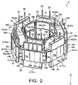
FIG. 2 is a perspective view showing a stator inFIG. 1 . -
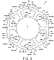
FIG. 3 is a plan view showing a stator core inFIG. 2 . -
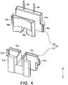
FIG. 4 is an exploded perspective view showing an insulator inFIG. 2 . -
FIG. 5A and FIG. 5B are enlarged views showing a part of a stator core shown inFIG. 3 . -
FIG. 6 is a plan view showing an original core body which becomes a stator core shown inFIG. 3 after being processed. -
FIG. 7A is an explanatory view showing a manufacturing method for a core plate which structures an original core body shown inFIG. 6 , andFIG. 7B is an enlarged view showing a part of a material plate shown inFIG. 7A . -
FIG. 8A and FIG. 8B are explanatory views showing a structure of a stator core in a prior art. - An embodiment of the present invention will be described below with reference to the accompanying drawings.
-
FIG. 1 is a cross-sectional view showing a pump device 1 in accordance with an embodiment of the present invention. In the following descriptions, an upper side inFIG. 1 ("Z1" direction side) is referred to as an "upper" side and a lower side inFIG. 1 ("Z2" direction side) is referred to as a "lower" side. - A pump device 1 in this embodiment is a pump referred to as a canned pump (canned motor pump), which includes an
impeller 2, a motor 3 structured to rotate theimpeller 2, and acircuit board 4 configured to control the motor 3. The motor 3 is structured of arotor 5 and astator 6. Theimpeller 2, the motor 3 and thecircuit board 4 are disposed inside a case body structured of ahousing 7 and anupper case 8 which covers an upper part of thehousing 7. Thehousing 7 and theupper case 8 are fixed to each other with a screw not shown. - The
upper case 8 is formed with anintake part 8a for a fluid and anejection part 8b for the fluid. A pump chamber 9 where a fluid inhaled through theintake part 8a is passed toward theejection part 8b is formed between thehousing 7 and theupper case 8. Further, a sealing member (O-ring) 10 is disposed in a joined portion between thehousing 7 and theupper case 8 for securing airtightness of the pump chamber 9. Thehousing 7 includes a partition member 11 which is disposed between the pump chamber 9 and thestator 6 so as to separate the pump chamber 9 from thestator 6, and aresin sealing member 12 made of resin which covers an under face and a side face of the partition member 11. - The
rotor 5 includes adrive magnet 14, asleeve 15 in a cylindrical tube shape, and a holdingmember 16 which holds thedrive magnet 14 and thesleeve 15. The holdingmember 16 is formed in a substantially cylindrical tube shape with a flange. Thedrive magnet 14 is fixed on an outer peripheral side of the holdingmember 16 and thesleeve 15 is fixed on an inner peripheral side of the holdingmember 16. Animpeller 2 is fixed to aflange part 16a disposed on an upper side of the holdingmember 16. Theimpeller 2 and therotor 5 are disposed inside the pump chamber 9. - The
rotor 5 is rotatably supported by a fixedshaft 17. The fixedshaft 17 is disposed so that an axial direction of the fixedshaft 17 and the upper and lower direction are coincided with each other. In other words, the upper and lower direction is an axial direction of therotor 5. An upper end of the fixedshaft 17 is held by theupper case 8 and a lower end of the fixedshaft 17 is held by thehousing 7. The fixedshaft 17 is inserted through an inner peripheral side of thesleeve 15. Further, the fixedshaft 17 is attached with athrust bearing member 18 which is abutted with an upper end face of thesleeve 15. In this embodiment, thesleeve 15 functions as a radial bearing for therotor 5, and thesleeve 15 and thethrust bearing member 18 function as a thrust bearing for therotor 5. - The
stator 6 includes drive coils 23 as a coil, astator core 24, andinsulators 25 as an insulation member, and thestator 6 is formed in a tube shape as a whole. Specifically, thestator 6 is formed in a substantially cylindrical tube shape. Thestator 6 is disposed on an outer peripheral side of therotor 5 through the partition member 11. In other words, therotor 5 is disposed on an inner peripheral side with respect to thestator 6. Further, thestator 6 is disposed so that an axial direction of thestator 6 and the upper and lower direction are coincided with each other. In other words, the upper and lower direction is an axial direction of thestator 6. Further, thestator 6 includesterminal pins 26 around which end parts of the drive coils 23 are bound and electrically connected. A specific structure of thestator 6 will be described below. In the following descriptions, a radial direction of therotor 5 and thestator 6 is referred to as a "radial direction", and a circumferential direction of therotor 5 and thestator 6 is referred to as a "circumferential direction". - The partition member 11 is formed in a substantially bottomed cylindrical tube shape with a flange and is provided with a
cylindrical tube part 11b, abottom part 11c and aflange part 11d. Thecylindrical tube part 11b is formed in a cylindrical tube shape and is disposed so as to cover an outer peripheral face of thedrive magnet 14. Further, thecylindrical tube part 11b is disposed so that an axial direction of thecylindrical tube part 11b and the upper and lower direction are substantially coincided with each other. Thebottom part 11c is formed in a substantially circular plate shape which closes a lower end of thecylindrical tube part 11b. Theflange part 11d is formed so as to be enlarged from an upper end of thecylindrical tube part 11b to an outer side in the radial direction. - An upper face of the
bottom part 11c is formed with ashaft holding part 11h which holds a lower end side of the fixedshaft 17 so as to protrude to an upper side. An under face of thebottom part 11c is formed with a fixingprojection 11j for fixing acircuit board 4 to the partition member 11 and apositioning projection 11k for positioning thecircuit board 4 so as to protrude to a lower side. As shown inFIG. 1 , an inner side and an upper side of the partition member 11 is structured to be the pump chamber 9, and theimpeller 2 and therotor 5 are disposed on the inner side and the upper side of the partition member 11. The partition member 11 functions to prevent the fluid inside the pump chamber 9 from flowing into an arrangement portion of thestator 6. - The
circuit board 4 is fixed to an under face side of thebottom part 11c so that a thickness direction of thecircuit board 4 and the upper and lower direction are coincided with each other. Specifically, thecircuit board 4 is fixed to the under face side of thebottom part 11c by ascrew 34 screwed into the fixingprojection 11j in a state positioned by the fixingprojection 11j and thepositioning projection 11k. Further, the lower end side portions of the terminal pins 26 are fixed to thecircuit board 4 by soldering. - The
resin sealing member 12 completely covers thecircuit board 4, the drive coils 23 and the like to protect thecircuit board 4, the drive coils 23 and the like from a fluid. Theresin sealing member 12 is formed by injecting resin material to the partition member 11 in a state that thecircuit board 4 and thestator 6 are attached to the partition member 11. Specifically, the partition member 11 to which thecircuit board 4 and thestator 6 have been attached is disposed inside a die and resin material is injected in the die and cured to form theresin sealing member 12. Theresin sealing member 12 is formed in a substantially bottomed cylindrical tube shape as a whole and completely covers thecircuit board 4, thestator 6, thecylindrical tube part 11b and thebottom part 11c. Further, theresin sealing member 12 covers an under face of theflange part 11d. -
FIG. 2 is a perspective view showing thestator 6 inFIG. 1 .FIG. 3 is a plan view showing thestator core 24 inFIG. 2 .FIG. 4 is an exploded perspective view showing theinsulator 25 inFIG. 2 .FIG. 5A and FIG. 5B are enlarged views showing a part of thestator core 24 shown inFIG. 3 . - The
stator 6 includes, as described above, the drive coils 23, thestator core 24, theinsulators 25 and the terminal pins 26. Thestator core 24 is a laminated core which is structured by laminating thin magnetic plates made of magnetic material. Thestator core 24 is, as shown inFIG. 3 , provided with an outerperipheral ring part 24a formed in a ring shape and a plurality ofsalient pole parts 24b which are protruded toward an inner side in the radial direction from the outerperipheral ring part 24a. Thestator core 24 in this embodiment is provided with sixsalient pole parts 24b. The sixsalient pole parts 24b are formed at equal angular pitches and are disposed at regular intervals in the circumferential direction. In accordance with an embodiment of the present invention, the number of thesalient pole parts 24b of thestator core 24 may be other than six. - A shape of an outer peripheral face of the outer
peripheral ring part 24a is a substantially circular shape when viewed in the upper and lower direction, and a shape of its inner peripheral face when viewed in the upper and lower direction is formed in a substantially hexagonal ring shape. The outer peripheral face of the outerperipheral ring part 24a structures an outer peripheral face of thestator core 24. An axial center of the outerperipheral ring part 24a when viewed in the upper and lower direction is an axial center of thestator core 24. Further, the axial center of thestator core 24 when viewed in the upper and lower direction is coincided with the axial center of thestator 6. - The outer
peripheral ring part 24a is structured of six outerperipheral parts 24e. In other words, the outerperipheral ring part 24a is structured of the same number of the outerperipheral parts 24e as that of thesalient pole parts 24b. One outerperipheral part 24e is one portion of the outerperipheral ring part 24a in the circumferential direction, which is a portion between one vertex and its adjacent vertex of the inner peripheral face of the outerperipheral ring part 24a which is formed in a substantially hexagonal shape when viewed in the upper and lower direction. In other words, one outerperipheral part 24e is one portion of the outerperipheral ring part 24a in the circumferential direction, which is a portion corresponding to one side of the inner peripheral face in a substantially hexagonal shape of the outerperipheral ring part 24a when viewed in the upper and lower direction. - The
salient pole part 24b is formed at a center of the outerperipheral part 24e in the circumferential direction. In other words, each of the six outerperipheral parts 24e is connected with onesalient pole part 24b. Further, thesalient pole part 24b is structured of a salient poletip end part 24c which is a tip end part of thesalient pole part 24b and a connectingpart 24d which connects the salient poletip end part 24c with the outerperipheral ring part 24a. When viewed in the upper and lower direction, the salient poletip end part 24c is formed in a substantially circular arc shape which is extended to both sides in the circumferential direction from a tip end (inner side end in the radial direction) of the connectingpart 24d which is formed in a straight line shape. An inner side face of the salient poletip end part 24c in the radial direction faces an outer peripheral face of thedrive magnet 14 through thecylindrical tube part 11b. - As described above, the outer
peripheral ring part 24a is formed in a ring shape whose shape of its inner peripheral face when viewed in the upper and lower direction is a substantially hexagonal shape and an inner side face of the outerperipheral part 24e in the radial direction is formed in a flat face perpendicular to the connectingpart 24d. A boundary portion of the outerperipheral parts 24e adjacent to each other in the circumferential direction is formed with aprotruded part 24f, which is protruded to an inner side in the radial direction, on the inner peripheral face of the outerperipheral ring part 24a. Theprotruded part 24f is formed so that a cross-sectional area of the outerperipheral ring part 24a at the boundary portion of the outerperipheral parts 24e adjacent to each other in the circumferential direction is secured to prevent magnetic saturation at the boundary portion. - When an outer side face of the outer
peripheral part 24e in the radial direction is referred to as an outerperipheral face 24g, each of both end side portions in the circumferential direction of the outerperipheral face 24g is formed to be acurved face part 24h which is a convex curved surface shape. Twocurved face parts 24h formed in one outerperipheral face 24g are formed in a circular arc shape so that, when viewed in the upper and lower direction, their curvature radii are equal and their centers of curvature are common. In this embodiment, the center of curvature "C1" (seeFIG. 3 ) of thecurved face part 24h when viewed in the upper and lower direction is coincided with an axial center of the stator 6 (in other words, an axial center of the stator core 24). An outer diameter of a portion between the twocurved face parts 24h in the circumferential direction of one outerperipheral face 24g is set to be smaller than an outer diameter (diameter) "D" of thecurved face part 24h (seeFIG. 5A ). In other words, as shown inFIG. 5A , when viewed in the upper and lower direction, a portion between the twocurved face parts 24h in the circumferential direction of one outerperipheral face 24g is disposed on an inner side in the radial direction with respect to an imaginary circular arc "VA" which is formed by connecting the twocurved face parts 24h and whose curvature radius is equal to that of thecurved face part 24h. Further, an outer diameter of the portion between the twocurved face parts 24h in the circumferential direction of one outerperipheral face 24g is longer in the circumferential direction than a length in the circumferential direction obtained by adding lengths of the twocurved face parts 24h. - A portion between the two
curved face parts 24h in the circumferential direction of one outerperipheral face 24g is formed with a secondcurved face part 24j in a convex curved surface shape which is formed in a circular arc shape when viewed in the upper and lower direction,flat face parts 24k as two first flat face parts in a flat face shape which are formed in a straight line shape when viewed in the upper and lower direction, andflat face parts 24n as two second flat face parts in a flat face shape which are formed in a straight line shape when viewed in the upper and lower direction. The secondcurved face part 24j is formed with a recessedpart 24p which is recessed toward an inner side in the radial direction. Each of one ends of the twoflat face parts 24n is connected with each of both end sides of the secondcurved face part 24j. Each of one ends of the twoflat face parts 24k is connected with each of the other ends of the twoflat face parts 24n, and each of the other ends of the twoflat face parts 24k is connected with each of the twocurved face parts 24h. In other words, theflat face part 24k and theflat face part 24n are formed between thecurved face part 24h and the secondcurved face part 24j in the circumferential direction of the outerperipheral face 24g. - The recessed
part 24p is formed in a circular arc shape when viewed in the upper and lower direction. Further, the recessedpart 24p is formed over the entire region of the secondcurved face part 24j in the upper and lower direction. In addition, the recessedpart 24p is formed at a center of the secondcurved face part 24j in the circumferential direction when viewed in the upper and lower direction. The secondcurved face part 24j is formed so that, when viewed in the upper and lower direction, a center of the secondcurved face part 24j and a center of thesalient pole part 24b in the circumferential direction are coincided with each other in the circumferential direction. In other words, the secondcurved face part 24j is formed so that a center of the secondcurved face part 24j in the circumferential direction and a center of thesalient pole part 24b are overlapped with each other in the radial direction when viewed in the upper and lower direction. As described above, the recessedpart 24p is formed at the center of the secondcurved face part 24j in the circumferential direction when viewed in the upper and lower direction, and thus the recessedpart 24p and thesalient pole part 24b are disposed so as to overlap with each other in the radial direction. - The
flat face part 24k is formed in a flat face shape perpendicular to the connectingpart 24d. One end of theflat face part 24k which is connected with the other end of theflat face part 24n is disposed on an outer side in the radial direction with respect to an end part of the secondcurved face part 24j. Theflat face parts 24n are formed from the respective both ends of the secondcurved face part 24j toward one ends of theflat face parts 24k (in other words, toward an outer side in the radial direction). In this embodiment, the curvature center of the secondcurved face part 24j is coincided with the curvature center "C1" of thecurved face part 24h and a curvature radius of the secondcurved face part 24j is smaller than a curvature radius of thecurved face part 24h. However, it may be structured that a curvature radius of the secondcurved face part 24j and a curvature radius of thecurved face part 24h are equal to each other and that a curvature center of the secondcurved face part 24j and a curvature center "C1" of thecurved face part 24h are separated from each other. - The
stator core 24 is a curling core which is structured so that six outerperipheral parts 24e connected with each other in a straight line shape (seeFIG. 6 ) are bent at boundaries between the outerperipheral parts 24e and that the end parts are connected with each other. In other words, thestator core 24 is formed in a ring shape by connecting end parts of the core with each other which is structured of a belt-shaped core which becomes the outerperipheral ring part 24a and sixsalient pole parts 24b extended from one face of the belt-shaped core. Therefore, as shown inFIG. 3 , a joint 24r is formed at one of positions between the outerperipheral parts 24e in the circumferential direction. In this embodiment, the end parts of the belt-shaped core are welded and fixed to each other in the joint 24r, and a welded mark is left in the joint 24r. - The
insulator 25 is formed of insulating material such as resin. Theinsulator 25 is attached to each of thesalient pole parts 24b and thestator 6 includes sixinsulators 25. In other words, thestator 6 includes the same number of theinsulators 25 as thesalient pole parts 24b. Further, theinsulator 25 is formed in a tube shape with flanges whose both ends are provided with flange parts and is attached to thesalient pole part 24b so that an axial direction of theinsulator 25 and the radial direction of thestator 6 are coincided with each other. Theinsulator 25 is structured of afirst insulator 30 and asecond insulator 31 which are capable of being divided in the upper and lower direction (seeFIG. 4 ), and thefirst insulator 30 and thesecond insulator 31 are combined with each other to form theinsulator 25. Thefirst insulator 30 is disposed on a lower side and thesecond insulator 31 is disposed on an upper side. - As shown in
FIG. 4 , thefirst insulator 30 is structured of ahalf tube part 30a in a rectangular groove shape, which covers side faces of a lower end side portion of the connectingpart 24d and an under face of the connectingpart 24d, an innerside flange part 30b which is connected with an inner side end in the radial direction of thehalf tube part 30a, and an outerside flange part 30c which is connected with an outer side end in the radial direction of thehalf tube part 30a. The innerside flange part 30b is formed in a flange shape which is enlarged from an inner side end of thehalf tube part 30a in the radial direction to both sides in the circumferential direction and to a lower side, and the innerside flange part 30b covers a lower end face of the salient poletip end part 24c and outer peripheral sides of a lower end side portion of the salient poletip end part 24c. - The outer
side flange part 30c is formed in a flange shape which is enlarged from an outer side end of thehalf tube part 30a in the radial direction to both sides in the circumferential direction and to a lower side, and the outerside flange part 30c covers a lower end face of a part of the outerperipheral part 24e (in other words, a part of the outerperipheral ring part 24a in the circumferential direction) and an inner peripheral side of a lower end side portion of a part of the outerperipheral part 24e. Further, as shown inFIGs. 4 and5B , acover part 30d which covers theprotruded part 24f from a lower side and covers a lower end side portion of theprotruded part 24f from thesalient pole part 24b side (in other words, covers from an inner side of the outerperipheral part 24e in the circumferential direction) is formed on both end sides of the outerside flange part 30c in the circumferential direction. - The
second insulator 31 is, as shown inFIG. 4 , structured of ahalf tube part 31a in a rectangular groove shape which covers side faces of an upper end side portion of the connectingpart 24d and an upper face of the connectingpart 24d, an innerside flange part 31b connected with an inner side end in the radial direction of thehalf tube part 31a, and an outerside flange part 31c connected with an outer side end in the radial direction of thehalf tube part 31a. The innerside flange part 31b is formed in a flange shape which is enlarged from an inner side end in the radial direction of thehalf tube part 31a toward both sides in the circumferential direction and toward an upper side, and the innerside flange part 31b covers an outer peripheral side of an upper end side portion of the salient poletip end part 24c. - The outer
side flange part 31c is formed in a flange shape which is enlarged from an outer side end in the radial direction of thehalf tube part 31a toward both sides in the circumferential direction and toward an upper side, and the outerside flange part 31c covers an upper end face of a part of the outerperipheral part 24e (in other words, a part in the circumferential direction of the outerperipheral ring part 24a) and an inner peripheral side of an upper end side portion of a part of the outerperipheral part 24e. Further, as shown inFIGs. 4 and5B , acover part 31d which covers theprotruded part 24f from an upper side and covers an upper end side portion of theprotruded part 24f from thesalient pole part 24b side (in other words, covers from an inner side of the outerperipheral part 24e in the circumferential direction) is formed on both end sides of the outerside flange part 31c in the circumferential direction. - At least an upper end side portion and a lower end side portion of the
protruded part 24f are covered by thecover part 30d and thecover part 31d from thesalient pole part 24b side. Thecover parts drive coil 23 from contacting with theprotruded part 24f when thedrive coil 23 is wound through theinsulator 25. Therefore, according to this embodiment, damage of a coating film of a conducting wire due to contact of the conducting wire structuring thedrive coil 23 with theprotruded part 24f can be prevented. - An upper end side portion of the
terminal pin 26 is press-fitted and fixed to thefirst insulator 30. In other words, theterminal pin 26 is fixed to thefirst insulator 30 so as to protrude from a lower end face of thefirst insulator 30. Further, twoterminal pins 26 are fixed to onefirst insulator 30. - The
drive coil 23 is structured of a conducting wire made of an aluminum alloy or a copper alloy. Thedrive coil 23 is wound around thesalient pole part 24b through theinsulator 25. Specifically, thedrive coil 23 is wound around the connectingpart 24d through thehalf tube parts drive coil 23 is bound and fixed to one of the twoterminal pins 26 fixed to thefirst insulator 30, and the other end part of thedrive coil 23 is bound and fixed to the other of the twoterminal pins 26. -
FIG. 6 is a plan view showing anoriginal core body 54 which becomes thestator core 24 shown inFIG. 3 after being processed.FIG. 7A is an explanatory view showing a manufacturing method for acore plate 55 which structures theoriginal core body 54 shown inFIG. 6 , andFIG. 7B is an enlarged view showing a part of a material plate 60 shown inFIG. 7A . - The
stator 6 is manufactured as described below. First, an original core body 54 (seeFIG. 6 ) which becomes thestator core 24 after being processed is manufactured. Anoriginal core body 54b is, as shown inFIG. 6 , provided with a belt-shapedpart 54b in a straight line shape, which is structured of six outerperipheral parts 24e connected with each other through bendingparts 54a, and sixsalient pole parts 24b each of which is protruded from each of the six outerperipheral parts 24e in a direction perpendicular to a longitudinal direction of the belt-shapedpart 54b. Thestator core 24 is a laminated core as described above. Thecore plate 55 has the same shape as theoriginal core body 54 when viewed in a thickness direction and theoriginal core body 54 is formed of thecore plates 55 in a thin plate shape which are laminated and fixed to each other. In this embodiment, protrudedparts 54c which become theprotruded part 24f after being processed are formed at both ends of the belt-shapedpart 54b and in the vicinities of thebending parts 54a. - In order to manufacture the
original core body 54, first, portions hatched with oblique lines inFIG. 7A are punched through a punching work by a press from a material plate 60 in a thin plate shape made of magnetic material to form a plurality ofcore plates 55. A die which is used in the press work is formed so that portions ofcore plates 55 to be punched which become belt-shapedparts 54b are adjacently disposed to each other, and that portions which becomesalient pole parts 24b of onecore plate 55 are disposed betweensalient pole parts 24b of anothercore plate 55. Further, a plurality ofcore plates 55 formed by punching the material plate 60 is laminated and fixed to each other to manufacture theoriginal core body 54. - After that, the
insulators 25 are attached to theoriginal core body 54. Further, the terminal pins 26 are press-fitted and fixed to thefirst insulator 30. After that, thedrive coil 23 is wound around thesalient pole part 24b through theinsulator 25 and thedrive coil 23 is soldered and fixed to theterminal pin 26. When thedrive coil 23 is to be wound around thesalient pole part 24b through theinsulator 25, contacting of a conducting wire structuring thedrive coil 23 with theprotruded part 24f of thestator core 24 is prevented by thecover parts insulator 25. - After that, the belt-shaped
part 54b is successively bent at thebending parts 54a so that the belt-shapedpart 54b in a straight line shape becomes the outerperipheral ring part 24a in a ring shape and that thesalient pole parts 24b are protruded to an inner side of the outerperipheral ring part 24a in a radial direction. When the belt-shapedpart 54b is to be bent, a bending jig (not shown) is pressed against the recessedparts 24p to bend the belt-shapedpart 54b. After that, the end parts of the belt-shapedpart 54b are connected with each other by welding or the like. When the end parts of the belt-shapedpart 54b are connected with each other, thestator 6 is completed. In this embodiment, when thestator 6 is completed, thecylindrical tube part 11b of the partition member 11 is inserted to an inner peripheral side of thestator 6. After that, thecircuit board 4 is fixed to the partition member 11 and the terminal pins 26 are soldered and fixed to thecircuit board 4. Further, after that, theresin sealing member 12 is formed so as to cover thestator 6 and thecircuit board 4. - As described above, in the
stator core 24 in this embodiment, an outer diameter of a portion between the twocurved face parts 24h in a circumferential direction of one outerperipheral face 24g is set to be smaller than the outer diameter "D" of thecurved face part 24h. Therefore, according to this embodiment, in a die for forming a plurality of thecore plates 55 from one material plate 60, a distance between portions of thecore plates 55 to be punched which become the belt-shapedparts 54b can be made smaller. In other words, in a case that the entire one outerperipheral face 24g is formed in one curved face shape whose curvature radius is equal to that of thecurved face part 24h, for example, a portion as shown by the alternate long and short dash line inFIG. 7B is interfered with a part of itsadjacent core plate 55. Therefore, in a die for forming thecore plate 55, portions of thecore plates 55 to be punched which become the belt-shapedparts 54b cannot be brought close to each other. However, in this embodiment, portions of thecore plates 55 to be punched which become the belt-shapedparts 54b can be brought close to each other. - Therefore, according to this embodiment, in comparison with a case that the entire one outer
peripheral face 24g is formed in one curved face shape, when a plurality ofcore plates 55 is to be formed by using a material plate 60,many core plates 55 can be formed from one material plate 60. In other words, in this embodiment, the number of thecore plates 55 to be obtained from one material plate 60 can be increased. Therefore, according to this embodiment, a manufacturing cost of thestator core 24 which is a curling core can be reduced. - In this embodiment, the
curved face part 24h is formed in a convex curved face shape which is a circular arc shape with an axial center of thestator 6 as the curvature center "C1". In other words, in this embodiment, a part of the outer peripheral face of the outerperipheral ring part 24a is formed in thecurved face part 24h in a convex curved face shape with the axial center of thestator 6 as the curvature center "C1". Therefore, according to this embodiment, while reducing an outer diameter of thestator core 24, a cross-sectional area of the outerperipheral ring part 24a can be secured. Accordingly, in this embodiment, while reducing the outer diameter of thestator core 24, magnetic saturation in the outerperipheral ring part 24a can be suppressed. - Further, in this embodiment, the second
curved face parts 24j in a convex curved face shape whose shape when viewed in the upper and lower direction is a circular arc shape are formed between the twocurved face parts 24h in the circumferential direction of one outerperipheral face 24g. Therefore, according to this embodiment, even when the recessedpart 24p is formed between the twocurved face parts 24h in the circumferential direction, in comparison with a case that the twocurved face parts 24h are connected with each other by a flat face part in a flat face shape, a cross-sectional area of the outerperipheral ring part 24a in a center portion of the outerperipheral part 24e in the circumferential direction can be secured. Accordingly, in this embodiment, magnetic saturation in the outerperipheral ring part 24a can be suppressed effectively. - Further, in the present invention, the outer diameter of the portion between the two
curved face parts 24h in the circumferential direction of one outerperipheral face 24g is longer in the circumferential direction than a length in the circumferential direction which is obtained by adding the twocurved face parts 24h. Therefore, according to this embodiment, in a die for forming a plurality of thecore plates 55 from one material plate 60, a distance between portions of thecore plates 55 to be punched which become the belt-shapedparts 54b can be further reduced. - Although the present invention has been shown and described with reference to a specific embodiment, various changes and modifications will be apparent to those skilled in the art from the teachings herein.
- In the embodiment described above, the
stator core 24 is a laminated core. However, thestator core 24 may be a core other than a laminated core. Even in this case, the number of theoriginal core bodies 54 to be obtained from one material plate can be increased and thus a manufacturing cost of thestator core 24 which is a curling core can be reduced. Further, in the embodiment described above, the curvature center "C1" of thecurved face part 24h when viewed in the upper and lower direction is coincided with the axial center of thestator 6. However, the curvature center "C1" may be displaced from the axial center of thestator 6. In addition, in the embodiment described above, the recessedpart 24p is formed in the outerperipheral part 24e. However, no recessedpart 24p may be formed in the outerperipheral part 24e. - In the embodiment described above, the
curved face part 24h and the secondcurved face part 24j are connected with each other through the twoflat face parts curved face part 24h and the secondcurved face part 24j may be connected with each other through one flat face part formed in a flat face shape. Further, in the embodiment described above, one secondcurved face part 24j is formed between the twocurved face parts 24h in the circumferential direction of one outerperipheral face 24g. However, in addition to the secondcurved face part 24j, one or more curved face parts which is different from the secondcurved face part 24j may be formed between the twocurved face parts 24h of one outerperipheral face 24g in the circumferential direction. In addition, in the embodiment described above, the secondcurved face part 24j is formed between the twocurved face part 24h in the circumferential direction of one outerperipheral face 24g. However, it may be structured that the twocurved face parts 24h are connected with each other through one flat face part formed in a flat face shape. - In the embodiment described above, each of the six
first insulators 30 and the sixsecond insulators 31 is attached to each of the sixsalient pole parts 24b, and thefirst insulator 30 and thesecond insulator 31 are divided for everysalient pole part 24b. However, thefirst insulator 30 and thesecond insulator 31 are not required to be divided for everysalient pole part 24b. For example, it may be structured that the sixfirst insulators 30 are integrally formed each other and the sixsecond insulators 31 are integrally formed each other. Further, in the embodiment described above, the motor 3 is used in a pump device 1. However, the motor 3 may be used in a device other than a pump device 1. Further, in the embodiment described above, thestator 6 is used in a motor 3. However, thestator 6 may be used in an electric power generator. -
- 1
- pump device
- 2
- impeller
- 3
- motor
- 5
- rotor
- 6
- stator
- 9
- pump chamber
- 11
- partition member
- 12
- resin sealing member
- 14
- drive magnet
- 23
- drive coil (coil)
- 24
- stator core
- 24a
- outer peripheral ring part
- 24b
- salient pole part
- 24e
- outer peripheral part
- 24g
- outer peripheral face
- 24h
- curved face part
- 24j
- second curved face part
- 24k
- flat face part
- 24p
- recessed part
- 25
- insulator (insulation member)
- "C1"
- curvature center
- "D"
- outer diameter of curved face part
Claims (10)
- A stator (6), being formed in a tube shape, and the stator (6) comprising:a coil (23);an insulation member (25); anda stator core (24) comprising a plurality of salient pole parts (24b), the coil (23) being wound around each of the plurality of the salient pole parts (24b) through the insulation member (25);wherein the stator core (24) comprises:an outer peripheral ring part (24a) which is formed in a ring shape; andthe plurality of the salient pole parts (24b) which are protruded from the outer peripheral ring part (24a) to an inner side in a radial direction of the stator (6) and are disposed at regular intervals in a circumferential direction of the stator (6);wherein the outer peripheral ring part (24a) is structured with a same number of outer peripheral parts (24e) as a number of the plurality of the salient pole parts (24b);wherein each of a plurality of the outer peripheral parts (24e) is connected with one of the salient pole parts (24b) and each salient pole part (24b) is formed at a center of an outer peripheral part (24e) in the circumferential direction;wherein when an outer side face of an outer peripheral part (24e) in the radial direction is referred to as an outer peripheral face (24g), both end side portions in the circumferential direction of the outer peripheral face (24g) of one of the outer peripheral parts (24e) are respectively formed to be a curved face part (24h) in a convex curved face shape which is a circular arc shape, said curved face parts (24h) have a same curvature radii and their curvature centers (C1) are common when viewed in an axial direction of the stator (6); andwherein an outer diameter of a portion between two of the curved face parts (24h) in the circumferential direction of the outer peripheral face (24g) of one of the outer peripheral parts (24e) is set to be smaller than an outer diameter (D) of the curved face parts (24h);the stator (6) being characterized in that,the outer peripheral face of one of the outer peripheral parts (24e) is formed with a second curved face part (24j) in a convex curved face shape, which is a circular arc shape when viewed in the axial direction and is located between two of the curved face parts (24h) in the circumferential direction.
- The stator (6) according to claim 1, wherein
when viewed in the axial direction, the curvature center (C1) of the curved face part (24h) is coincided with an axial center of the stator (6). - The stator (6) according to claim 1, wherein
the outer peripheral face of one of the outer peripheral parts (24e) is formed with a flat face part (24n) in a flat face shape, which is a straight line shape when viewed in the axial direction, between the curved face part (24h) and the second curved face part (24j) in the circumferential direction. - The stator (6) according to claim 1, wherein
the second curved face part (24j) is formed with a recessed part (24p) which is recessed to an inner side in the radial direction,
the recessed part (24p) is formed over an entire region in the axial direction of the second curved face part (24j) and is formed in a circular arc shape when viewed in the axial direction, and
the salient pole part (24b) and the recessed part (24p) are disposed so as to overlap in the radial direction. - The stator (6) according to claim 1, wherein
the outer peripheral face of one of the outer peripheral parts (24e) is formed between the curved face part (24h) and the second curved face part (24j) in the circumferential direction with:a first flat face part (24k) in a flat face shape which is a straight line shape when viewed in the axial direction and is connected with the curved face part (24h); anda second flat face part (24n) in a flat face shape which is a straight line shape when viewed in the axial direction and is connected with the first flat face part (24k) and the second curved face part (24j). - The stator (6) according to claim 1, wherein
a boundary portion of the outer peripheral parts (24e) adjacent to each other in the circumferential direction is formed with a protruded part (24f) protruding to an inner side in the radial direction in an inner peripheral face of the outer peripheral ring part (24a). - The stator (6) according to claim 1, wherein
a portion between two of the curved face parts (24h) in the circumferential direction of the outer peripheral face (24g) of one of the outer peripheral parts (24e) is longer in the circumferential direction than a length obtained by adding two of the curved face parts (24h) in the circumferential direction. - The stator (6) according to claim 1, wherein
a curvature center of the second curved face part (24j) is coincided with a curvature center (C1) of the curved face part (24h), and
a curvature radius of the second curved face part (24j) is set to be smaller than a curvature radius of the curved face part (24h). - A motor (3), characterized in that the motor (3) comprising:the stator (6) as defined in one of claims 1 through 8; anda rotor (5) which comprises a drive magnet (14) and is disposed on an inner peripheral side with respect to the stator (6).
- A pump device (1), characterized in that the pump device (1) comprises:the motor (3) defined in claim 9;an impeller (2) which is attached to the rotor (5);a pump chamber (9) in which the impeller (2) and the rotor (5) are disposed and through which a fluid is passed;a partition member (11) which is disposed between the stator (6) and the pump chamber (9) and which prevents an inflow of the fluid in the pump chamber (9) into an arrangement portion of the stator (6); anda resin sealing member (12) made of resin which covers the stator (6).
Applications Claiming Priority (2)
| Application Number | Priority Date | Filing Date | Title |
|---|---|---|---|
| JP2015193972A JP6649733B2 (en) | 2015-09-30 | 2015-09-30 | Stator, motor and pump device |
| PCT/JP2016/078584 WO2017057438A1 (en) | 2015-09-30 | 2016-09-28 | Stator, motor, and pump device |
Publications (3)
| Publication Number | Publication Date |
|---|---|
| EP3358715A1 EP3358715A1 (en) | 2018-08-08 |
| EP3358715A4 EP3358715A4 (en) | 2018-11-07 |
| EP3358715B1 true EP3358715B1 (en) | 2020-05-06 |
Family
ID=58423913
Family Applications (1)
| Application Number | Title | Priority Date | Filing Date |
|---|---|---|---|
| EP16851609.4A Active EP3358715B1 (en) | 2015-09-30 | 2016-09-28 | Stator, motor, and pump device |
Country Status (5)
| Country | Link |
|---|---|
| US (1) | US10848018B2 (en) |
| EP (1) | EP3358715B1 (en) |
| JP (1) | JP6649733B2 (en) |
| CN (2) | CN106571698B (en) |
| WO (1) | WO2017057438A1 (en) |
Families Citing this family (9)
| Publication number | Priority date | Publication date | Assignee | Title |
|---|---|---|---|---|
| JP6649733B2 (en) * | 2015-09-30 | 2020-02-19 | 日本電産サンキョー株式会社 | Stator, motor and pump device |
| JP2017135861A (en) * | 2016-01-28 | 2017-08-03 | 日本電産サンキョー株式会社 | Stator and manufacturing method of stator |
| JP7027771B2 (en) * | 2017-09-29 | 2022-03-02 | 日本電産株式会社 | Motors, motor units, and stators |
| FR3072517B1 (en) * | 2017-10-17 | 2020-12-18 | Moving Magnet Tech | TOROIDAL POLYPHASED ELECTRIC MACHINE |
| CN112640259A (en) * | 2018-08-24 | 2021-04-09 | 美蓓亚三美株式会社 | Motor and method for manufacturing motor |
| JP2020058115A (en) * | 2018-09-28 | 2020-04-09 | 日本電産株式会社 | motor |
| JP2020105957A (en) * | 2018-12-27 | 2020-07-09 | 愛三工業株式会社 | pump |
| JP7182489B2 (en) * | 2019-02-08 | 2022-12-02 | マブチモーター株式会社 | resolver and motor |
| CN114583855A (en) * | 2020-12-01 | 2022-06-03 | 创科无线普通合伙 | Stator core assembly, stator assembly, motor device and method thereof |
Family Cites Families (14)
| Publication number | Priority date | Publication date | Assignee | Title |
|---|---|---|---|---|
| JP2004201428A (en) * | 2002-12-19 | 2004-07-15 | Matsushita Electric Ind Co Ltd | Motor |
| JP4057449B2 (en) * | 2003-03-10 | 2008-03-05 | アスモ株式会社 | Rotating electrical machine core |
| DE10338453A1 (en) * | 2003-08-21 | 2005-03-31 | Robert Bosch Gmbh | Main element for an electrical machine |
| US7414347B2 (en) | 2004-03-23 | 2008-08-19 | Emerson Electric Co. | End cap for segmented stator |
| JP2007032370A (en) * | 2005-07-25 | 2007-02-08 | Aisin Seiki Co Ltd | Electric pump |
| JP4760503B2 (en) * | 2006-04-07 | 2011-08-31 | パナソニック電工株式会社 | Pump and pump manufacturing method |
| JP4841536B2 (en) * | 2007-11-30 | 2011-12-21 | 三菱電機株式会社 | Motor and refrigerant compressor provided with the same |
| JP4884418B2 (en) * | 2008-04-04 | 2012-02-29 | 三菱電機株式会社 | Manufacturing method of split stator core |
| JP4948474B2 (en) | 2008-05-16 | 2012-06-06 | 株式会社富士通ゼネラル | Electric motor |
| JP2010057211A (en) | 2008-08-26 | 2010-03-11 | Nippon Densan Corp | Motor |
| US9903372B2 (en) * | 2012-10-05 | 2018-02-27 | Mitsubishi Electric Corporation | Pump, method for manufacturing pump, and refrigeration cycle device |
| DE102012025049A1 (en) | 2012-12-20 | 2014-06-26 | Robert Bosch Gmbh | Method for producing a synchronous motor |
| JP6102779B2 (en) * | 2014-02-07 | 2017-03-29 | 株式会社デンソー | Stator core of rotating electrical machine |
| JP6649733B2 (en) * | 2015-09-30 | 2020-02-19 | 日本電産サンキョー株式会社 | Stator, motor and pump device |
-
2015
- 2015-09-30 JP JP2015193972A patent/JP6649733B2/en active Active
-
2016
- 2016-09-27 CN CN201610857157.5A patent/CN106571698B/en active Active
- 2016-09-27 CN CN201621086249.XU patent/CN206149033U/en not_active Withdrawn - After Issue
- 2016-09-28 WO PCT/JP2016/078584 patent/WO2017057438A1/en unknown
- 2016-09-28 EP EP16851609.4A patent/EP3358715B1/en active Active
- 2016-09-28 US US15/761,430 patent/US10848018B2/en active Active
Non-Patent Citations (1)
| Title |
|---|
| None * |
Also Published As
| Publication number | Publication date |
|---|---|
| JP2017070111A (en) | 2017-04-06 |
| CN106571698B (en) | 2019-03-29 |
| EP3358715A4 (en) | 2018-11-07 |
| US10848018B2 (en) | 2020-11-24 |
| JP6649733B2 (en) | 2020-02-19 |
| CN206149033U (en) | 2017-05-03 |
| WO2017057438A1 (en) | 2017-04-06 |
| EP3358715A1 (en) | 2018-08-08 |
| CN106571698A (en) | 2017-04-19 |
| US20190052130A1 (en) | 2019-02-14 |
Similar Documents
| Publication | Publication Date | Title |
|---|---|---|
| EP3358715B1 (en) | Stator, motor, and pump device | |
| EP3200320B1 (en) | Stator and manufacturing method therefor | |
| JP6190599B2 (en) | Manufacturing method of bus bar unit | |
| CN112368912B (en) | Radial gap type rotary motor with distributed winding method and stator thereof | |
| EP3151391B1 (en) | Motor and method for manufacturing motor | |
| US11329526B2 (en) | Stator, stator assembly, and transducer for converting between electrical energy and mechanical energy | |
| JP6138360B2 (en) | Rotating electric machine and manufacturing method thereof | |
| JP6124493B1 (en) | Rotating electric machine for internal combustion engine and stator thereof | |
| KR20170017912A (en) | Stator of an electric machine | |
| US20170070115A1 (en) | Stator, brushless motor, and stator manufacturing method | |
| US20150102696A1 (en) | Armature, rotating electrical device, and armature manufacturing method | |
| CN111628594B (en) | Converter of electric energy and mechanical energy | |
| US20210288543A1 (en) | Stator for Rotary Electric Machine, Method of Manufacturing Stator for Rotary Electric Machine, and Rotary Electric Machine | |
| JP2018117469A (en) | Stator of rotary electric machine | |
| CN116613910A (en) | Motor and method for manufacturing the same | |
| EP3358714A1 (en) | Stator, motor, and pump device | |
| JP2010259174A (en) | Method of manufacturing motor stators | |
| JP6592284B2 (en) | FEEDING RING AND METHOD FOR MANUFACTURING FEEDING RING | |
| JP6514978B2 (en) | Stator, motor and method of manufacturing stator | |
| US20220302787A1 (en) | Stator and method for manufacturing stator | |
| JP2011229290A (en) | Motor | |
| JP7113959B2 (en) | STATOR, ROTATING ELECTRICAL MACHINE, AND STATOR MANUFACTURING METHOD | |
| WO2017175358A1 (en) | Stator and electric motor | |
| JP7205454B2 (en) | Stators, stator assemblies, converters between electrical and mechanical energy | |
| JP2017011828A (en) | Power supply ring and method of manufacturing power supply ring |
Legal Events
| Date | Code | Title | Description |
|---|---|---|---|
| STAA | Information on the status of an ep patent application or granted ep patent |
Free format text: STATUS: THE INTERNATIONAL PUBLICATION HAS BEEN MADE |
|
| PUAI | Public reference made under article 153(3) epc to a published international application that has entered the european phase |
Free format text: ORIGINAL CODE: 0009012 |
|
| STAA | Information on the status of an ep patent application or granted ep patent |
Free format text: STATUS: REQUEST FOR EXAMINATION WAS MADE |
|
| 17P | Request for examination filed |
Effective date: 20180430 |
|
| AK | Designated contracting states |
Kind code of ref document: A1 Designated state(s): AL AT BE BG CH CY CZ DE DK EE ES FI FR GB GR HR HU IE IS IT LI LT LU LV MC MK MT NL NO PL PT RO RS SE SI SK SM TR |
|
| AX | Request for extension of the european patent |
Extension state: BA ME |
|
| A4 | Supplementary search report drawn up and despatched |
Effective date: 20181009 |
|
| RIC1 | Information provided on ipc code assigned before grant |
Ipc: H02K 1/14 20060101AFI20181003BHEP Ipc: H02K 29/03 20060101ALN20181003BHEP |
|
| DAV | Request for validation of the european patent (deleted) | ||
| DAX | Request for extension of the european patent (deleted) | ||
| REG | Reference to a national code |
Ref country code: DE Ref legal event code: R079 Ref document number: 602016036139 Country of ref document: DE Free format text: PREVIOUS MAIN CLASS: H02K0001180000 Ipc: H02K0001140000 |
|
| GRAP | Despatch of communication of intention to grant a patent |
Free format text: ORIGINAL CODE: EPIDOSNIGR1 |
|
| STAA | Information on the status of an ep patent application or granted ep patent |
Free format text: STATUS: GRANT OF PATENT IS INTENDED |
|
| RIC1 | Information provided on ipc code assigned before grant |
Ipc: H02K 29/03 20060101ALN20200115BHEP Ipc: H02K 1/14 20060101AFI20200115BHEP |
|
| RIC1 | Information provided on ipc code assigned before grant |
Ipc: H02K 1/14 20060101AFI20200121BHEP Ipc: H02K 29/03 20060101ALN20200121BHEP |
|
| INTG | Intention to grant announced |
Effective date: 20200206 |
|
| RIC1 | Information provided on ipc code assigned before grant |
Ipc: H02K 29/03 20060101ALN20200129BHEP Ipc: H02K 1/14 20060101AFI20200129BHEP |
|
| GRAS | Grant fee paid |
Free format text: ORIGINAL CODE: EPIDOSNIGR3 |
|
| GRAA | (expected) grant |
Free format text: ORIGINAL CODE: 0009210 |
|
| STAA | Information on the status of an ep patent application or granted ep patent |
Free format text: STATUS: THE PATENT HAS BEEN GRANTED |
|
| AK | Designated contracting states |
Kind code of ref document: B1 Designated state(s): AL AT BE BG CH CY CZ DE DK EE ES FI FR GB GR HR HU IE IS IT LI LT LU LV MC MK MT NL NO PL PT RO RS SE SI SK SM TR |
|
| REG | Reference to a national code |
Ref country code: GB Ref legal event code: FG4D |
|
| REG | Reference to a national code |
Ref country code: CH Ref legal event code: EP Ref country code: AT Ref legal event code: REF Ref document number: 1268395 Country of ref document: AT Kind code of ref document: T Effective date: 20200515 |
|
| REG | Reference to a national code |
Ref country code: IE Ref legal event code: FG4D |
|
| REG | Reference to a national code |
Ref country code: DE Ref legal event code: R096 Ref document number: 602016036139 Country of ref document: DE |
|
| REG | Reference to a national code |
Ref country code: LT Ref legal event code: MG4D |
|
| REG | Reference to a national code |
Ref country code: NL Ref legal event code: MP Effective date: 20200506 |
|
| PG25 | Lapsed in a contracting state [announced via postgrant information from national office to epo] |
Ref country code: PT Free format text: LAPSE BECAUSE OF FAILURE TO SUBMIT A TRANSLATION OF THE DESCRIPTION OR TO PAY THE FEE WITHIN THE PRESCRIBED TIME-LIMIT Effective date: 20200907 Ref country code: FI Free format text: LAPSE BECAUSE OF FAILURE TO SUBMIT A TRANSLATION OF THE DESCRIPTION OR TO PAY THE FEE WITHIN THE PRESCRIBED TIME-LIMIT Effective date: 20200506 Ref country code: LT Free format text: LAPSE BECAUSE OF FAILURE TO SUBMIT A TRANSLATION OF THE DESCRIPTION OR TO PAY THE FEE WITHIN THE PRESCRIBED TIME-LIMIT Effective date: 20200506 Ref country code: IS Free format text: LAPSE BECAUSE OF FAILURE TO SUBMIT A TRANSLATION OF THE DESCRIPTION OR TO PAY THE FEE WITHIN THE PRESCRIBED TIME-LIMIT Effective date: 20200906 Ref country code: SE Free format text: LAPSE BECAUSE OF FAILURE TO SUBMIT A TRANSLATION OF THE DESCRIPTION OR TO PAY THE FEE WITHIN THE PRESCRIBED TIME-LIMIT Effective date: 20200506 Ref country code: NO Free format text: LAPSE BECAUSE OF FAILURE TO SUBMIT A TRANSLATION OF THE DESCRIPTION OR TO PAY THE FEE WITHIN THE PRESCRIBED TIME-LIMIT Effective date: 20200806 Ref country code: GR Free format text: LAPSE BECAUSE OF FAILURE TO SUBMIT A TRANSLATION OF THE DESCRIPTION OR TO PAY THE FEE WITHIN THE PRESCRIBED TIME-LIMIT Effective date: 20200807 |
|
| PG25 | Lapsed in a contracting state [announced via postgrant information from national office to epo] |
Ref country code: BG Free format text: LAPSE BECAUSE OF FAILURE TO SUBMIT A TRANSLATION OF THE DESCRIPTION OR TO PAY THE FEE WITHIN THE PRESCRIBED TIME-LIMIT Effective date: 20200806 Ref country code: HR Free format text: LAPSE BECAUSE OF FAILURE TO SUBMIT A TRANSLATION OF THE DESCRIPTION OR TO PAY THE FEE WITHIN THE PRESCRIBED TIME-LIMIT Effective date: 20200506 Ref country code: RS Free format text: LAPSE BECAUSE OF FAILURE TO SUBMIT A TRANSLATION OF THE DESCRIPTION OR TO PAY THE FEE WITHIN THE PRESCRIBED TIME-LIMIT Effective date: 20200506 Ref country code: LV Free format text: LAPSE BECAUSE OF FAILURE TO SUBMIT A TRANSLATION OF THE DESCRIPTION OR TO PAY THE FEE WITHIN THE PRESCRIBED TIME-LIMIT Effective date: 20200506 |
|
| REG | Reference to a national code |
Ref country code: AT Ref legal event code: MK05 Ref document number: 1268395 Country of ref document: AT Kind code of ref document: T Effective date: 20200506 |
|
| PG25 | Lapsed in a contracting state [announced via postgrant information from national office to epo] |
Ref country code: AL Free format text: LAPSE BECAUSE OF FAILURE TO SUBMIT A TRANSLATION OF THE DESCRIPTION OR TO PAY THE FEE WITHIN THE PRESCRIBED TIME-LIMIT Effective date: 20200506 Ref country code: NL Free format text: LAPSE BECAUSE OF FAILURE TO SUBMIT A TRANSLATION OF THE DESCRIPTION OR TO PAY THE FEE WITHIN THE PRESCRIBED TIME-LIMIT Effective date: 20200506 |
|
| PG25 | Lapsed in a contracting state [announced via postgrant information from national office to epo] |
Ref country code: SM Free format text: LAPSE BECAUSE OF FAILURE TO SUBMIT A TRANSLATION OF THE DESCRIPTION OR TO PAY THE FEE WITHIN THE PRESCRIBED TIME-LIMIT Effective date: 20200506 Ref country code: EE Free format text: LAPSE BECAUSE OF FAILURE TO SUBMIT A TRANSLATION OF THE DESCRIPTION OR TO PAY THE FEE WITHIN THE PRESCRIBED TIME-LIMIT Effective date: 20200506 Ref country code: DK Free format text: LAPSE BECAUSE OF FAILURE TO SUBMIT A TRANSLATION OF THE DESCRIPTION OR TO PAY THE FEE WITHIN THE PRESCRIBED TIME-LIMIT Effective date: 20200506 Ref country code: RO Free format text: LAPSE BECAUSE OF FAILURE TO SUBMIT A TRANSLATION OF THE DESCRIPTION OR TO PAY THE FEE WITHIN THE PRESCRIBED TIME-LIMIT Effective date: 20200506 Ref country code: IT Free format text: LAPSE BECAUSE OF FAILURE TO SUBMIT A TRANSLATION OF THE DESCRIPTION OR TO PAY THE FEE WITHIN THE PRESCRIBED TIME-LIMIT Effective date: 20200506 Ref country code: CZ Free format text: LAPSE BECAUSE OF FAILURE TO SUBMIT A TRANSLATION OF THE DESCRIPTION OR TO PAY THE FEE WITHIN THE PRESCRIBED TIME-LIMIT Effective date: 20200506 Ref country code: AT Free format text: LAPSE BECAUSE OF FAILURE TO SUBMIT A TRANSLATION OF THE DESCRIPTION OR TO PAY THE FEE WITHIN THE PRESCRIBED TIME-LIMIT Effective date: 20200506 Ref country code: ES Free format text: LAPSE BECAUSE OF FAILURE TO SUBMIT A TRANSLATION OF THE DESCRIPTION OR TO PAY THE FEE WITHIN THE PRESCRIBED TIME-LIMIT Effective date: 20200506 |
|
| PGFP | Annual fee paid to national office [announced via postgrant information from national office to epo] |
Ref country code: DE Payment date: 20200930 Year of fee payment: 5 |
|
| REG | Reference to a national code |
Ref country code: DE Ref legal event code: R097 Ref document number: 602016036139 Country of ref document: DE |
|
| PG25 | Lapsed in a contracting state [announced via postgrant information from national office to epo] |
Ref country code: PL Free format text: LAPSE BECAUSE OF FAILURE TO SUBMIT A TRANSLATION OF THE DESCRIPTION OR TO PAY THE FEE WITHIN THE PRESCRIBED TIME-LIMIT Effective date: 20200506 Ref country code: SK Free format text: LAPSE BECAUSE OF FAILURE TO SUBMIT A TRANSLATION OF THE DESCRIPTION OR TO PAY THE FEE WITHIN THE PRESCRIBED TIME-LIMIT Effective date: 20200506 |
|
| PLBE | No opposition filed within time limit |
Free format text: ORIGINAL CODE: 0009261 |
|
| STAA | Information on the status of an ep patent application or granted ep patent |
Free format text: STATUS: NO OPPOSITION FILED WITHIN TIME LIMIT |
|
| 26N | No opposition filed |
Effective date: 20210209 |
|
| REG | Reference to a national code |
Ref country code: CH Ref legal event code: PL |
|
| GBPC | Gb: european patent ceased through non-payment of renewal fee |
Effective date: 20200928 |
|
| PG25 | Lapsed in a contracting state [announced via postgrant information from national office to epo] |
Ref country code: SI Free format text: LAPSE BECAUSE OF FAILURE TO SUBMIT A TRANSLATION OF THE DESCRIPTION OR TO PAY THE FEE WITHIN THE PRESCRIBED TIME-LIMIT Effective date: 20200506 |
|
| REG | Reference to a national code |
Ref country code: BE Ref legal event code: MM Effective date: 20200930 |
|
| PG25 | Lapsed in a contracting state [announced via postgrant information from national office to epo] |
Ref country code: LU Free format text: LAPSE BECAUSE OF NON-PAYMENT OF DUE FEES Effective date: 20200928 |
|
| PG25 | Lapsed in a contracting state [announced via postgrant information from national office to epo] |
Ref country code: FR Free format text: LAPSE BECAUSE OF NON-PAYMENT OF DUE FEES Effective date: 20200930 |
|
| PG25 | Lapsed in a contracting state [announced via postgrant information from national office to epo] |
Ref country code: BE Free format text: LAPSE BECAUSE OF NON-PAYMENT OF DUE FEES Effective date: 20200930 Ref country code: CH Free format text: LAPSE BECAUSE OF NON-PAYMENT OF DUE FEES Effective date: 20200930 Ref country code: LI Free format text: LAPSE BECAUSE OF NON-PAYMENT OF DUE FEES Effective date: 20200930 Ref country code: IE Free format text: LAPSE BECAUSE OF NON-PAYMENT OF DUE FEES Effective date: 20200928 Ref country code: GB Free format text: LAPSE BECAUSE OF NON-PAYMENT OF DUE FEES Effective date: 20200928 |
|
| REG | Reference to a national code |
Ref country code: DE Ref legal event code: R119 Ref document number: 602016036139 Country of ref document: DE |
|
| PG25 | Lapsed in a contracting state [announced via postgrant information from national office to epo] |
Ref country code: TR Free format text: LAPSE BECAUSE OF FAILURE TO SUBMIT A TRANSLATION OF THE DESCRIPTION OR TO PAY THE FEE WITHIN THE PRESCRIBED TIME-LIMIT Effective date: 20200506 Ref country code: MT Free format text: LAPSE BECAUSE OF FAILURE TO SUBMIT A TRANSLATION OF THE DESCRIPTION OR TO PAY THE FEE WITHIN THE PRESCRIBED TIME-LIMIT Effective date: 20200506 Ref country code: CY Free format text: LAPSE BECAUSE OF FAILURE TO SUBMIT A TRANSLATION OF THE DESCRIPTION OR TO PAY THE FEE WITHIN THE PRESCRIBED TIME-LIMIT Effective date: 20200506 |
|
| PG25 | Lapsed in a contracting state [announced via postgrant information from national office to epo] |
Ref country code: MK Free format text: LAPSE BECAUSE OF FAILURE TO SUBMIT A TRANSLATION OF THE DESCRIPTION OR TO PAY THE FEE WITHIN THE PRESCRIBED TIME-LIMIT Effective date: 20200506 Ref country code: MC Free format text: LAPSE BECAUSE OF FAILURE TO SUBMIT A TRANSLATION OF THE DESCRIPTION OR TO PAY THE FEE WITHIN THE PRESCRIBED TIME-LIMIT Effective date: 20200506 |
|
| PG25 | Lapsed in a contracting state [announced via postgrant information from national office to epo] |
Ref country code: DE Free format text: LAPSE BECAUSE OF NON-PAYMENT OF DUE FEES Effective date: 20220401 |