EP3358451B1 - Elektronische vorrichtung zur variablen anzeige der position eines objekts eines erweiterungsbereichs von anzeigen und anzeigeverfahren - Google Patents
Elektronische vorrichtung zur variablen anzeige der position eines objekts eines erweiterungsbereichs von anzeigen und anzeigeverfahren Download PDFInfo
- Publication number
- EP3358451B1 EP3358451B1 EP18154898.3A EP18154898A EP3358451B1 EP 3358451 B1 EP3358451 B1 EP 3358451B1 EP 18154898 A EP18154898 A EP 18154898A EP 3358451 B1 EP3358451 B1 EP 3358451B1
- Authority
- EP
- European Patent Office
- Prior art keywords
- display
- sensor
- electronic device
- surface area
- processor
- Prior art date
- Legal status (The legal status is an assumption and is not a legal conclusion. Google has not performed a legal analysis and makes no representation as to the accuracy of the status listed.)
- Active
Links
Images


Classifications
-
- G—PHYSICS
- G06—COMPUTING OR CALCULATING; COUNTING
- G06F—ELECTRIC DIGITAL DATA PROCESSING
- G06F3/00—Input arrangements for transferring data to be processed into a form capable of being handled by the computer; Output arrangements for transferring data from processing unit to output unit, e.g. interface arrangements
- G06F3/01—Input arrangements or combined input and output arrangements for interaction between user and computer
- G06F3/03—Arrangements for converting the position or the displacement of a member into a coded form
- G06F3/041—Digitisers, e.g. for touch screens or touch pads, characterised by the transducing means
- G06F3/0414—Digitisers, e.g. for touch screens or touch pads, characterised by the transducing means using force sensing means to determine a position
- G06F3/04142—Digitisers, e.g. for touch screens or touch pads, characterised by the transducing means using force sensing means to determine a position the force sensing means being located peripherally, e.g. disposed at the corners or at the side of a touch sensing plate
-
- G—PHYSICS
- G06—COMPUTING OR CALCULATING; COUNTING
- G06F—ELECTRIC DIGITAL DATA PROCESSING
- G06F3/00—Input arrangements for transferring data to be processed into a form capable of being handled by the computer; Output arrangements for transferring data from processing unit to output unit, e.g. interface arrangements
- G06F3/01—Input arrangements or combined input and output arrangements for interaction between user and computer
- G06F3/03—Arrangements for converting the position or the displacement of a member into a coded form
- G06F3/041—Digitisers, e.g. for touch screens or touch pads, characterised by the transducing means
- G06F3/0412—Digitisers structurally integrated in a display
-
- G—PHYSICS
- G06—COMPUTING OR CALCULATING; COUNTING
- G06F—ELECTRIC DIGITAL DATA PROCESSING
- G06F3/00—Input arrangements for transferring data to be processed into a form capable of being handled by the computer; Output arrangements for transferring data from processing unit to output unit, e.g. interface arrangements
- G06F3/01—Input arrangements or combined input and output arrangements for interaction between user and computer
- G06F3/048—Interaction techniques based on graphical user interfaces [GUI]
- G06F3/0487—Interaction techniques based on graphical user interfaces [GUI] using specific features provided by the input device, e.g. functions controlled by the rotation of a mouse with dual sensing arrangements, or of the nature of the input device, e.g. tap gestures based on pressure sensed by a digitiser
- G06F3/0488—Interaction techniques based on graphical user interfaces [GUI] using specific features provided by the input device, e.g. functions controlled by the rotation of a mouse with dual sensing arrangements, or of the nature of the input device, e.g. tap gestures based on pressure sensed by a digitiser using a touch-screen or digitiser, e.g. input of commands through traced gestures
- G06F3/04886—Interaction techniques based on graphical user interfaces [GUI] using specific features provided by the input device, e.g. functions controlled by the rotation of a mouse with dual sensing arrangements, or of the nature of the input device, e.g. tap gestures based on pressure sensed by a digitiser using a touch-screen or digitiser, e.g. input of commands through traced gestures by partitioning the display area of the touch-screen or the surface of the digitising tablet into independently controllable areas, e.g. virtual keyboards or menus
-
- G—PHYSICS
- G06—COMPUTING OR CALCULATING; COUNTING
- G06F—ELECTRIC DIGITAL DATA PROCESSING
- G06F1/00—Details not covered by groups G06F3/00 - G06F13/00 and G06F21/00
- G06F1/16—Constructional details or arrangements
- G06F1/1613—Constructional details or arrangements for portable computers
- G06F1/1633—Constructional details or arrangements of portable computers not specific to the type of enclosures covered by groups G06F1/1615 - G06F1/1626
- G06F1/1637—Details related to the display arrangement, including those related to the mounting of the display in the housing
-
- G—PHYSICS
- G06—COMPUTING OR CALCULATING; COUNTING
- G06F—ELECTRIC DIGITAL DATA PROCESSING
- G06F3/00—Input arrangements for transferring data to be processed into a form capable of being handled by the computer; Output arrangements for transferring data from processing unit to output unit, e.g. interface arrangements
- G06F3/01—Input arrangements or combined input and output arrangements for interaction between user and computer
- G06F3/017—Gesture based interaction, e.g. based on a set of recognized hand gestures
-
- G—PHYSICS
- G06—COMPUTING OR CALCULATING; COUNTING
- G06F—ELECTRIC DIGITAL DATA PROCESSING
- G06F3/00—Input arrangements for transferring data to be processed into a form capable of being handled by the computer; Output arrangements for transferring data from processing unit to output unit, e.g. interface arrangements
- G06F3/01—Input arrangements or combined input and output arrangements for interaction between user and computer
- G06F3/03—Arrangements for converting the position or the displacement of a member into a coded form
- G06F3/033—Pointing devices displaced or positioned by the user, e.g. mice, trackballs, pens or joysticks; Accessories therefor
- G06F3/0346—Pointing devices displaced or positioned by the user, e.g. mice, trackballs, pens or joysticks; Accessories therefor with detection of the device orientation or free movement in a 3D space, e.g. 3D mice, 6-DOF [six degrees of freedom] pointers using gyroscopes, accelerometers or tilt-sensors
-
- G—PHYSICS
- G06—COMPUTING OR CALCULATING; COUNTING
- G06F—ELECTRIC DIGITAL DATA PROCESSING
- G06F3/00—Input arrangements for transferring data to be processed into a form capable of being handled by the computer; Output arrangements for transferring data from processing unit to output unit, e.g. interface arrangements
- G06F3/01—Input arrangements or combined input and output arrangements for interaction between user and computer
- G06F3/03—Arrangements for converting the position or the displacement of a member into a coded form
- G06F3/041—Digitisers, e.g. for touch screens or touch pads, characterised by the transducing means
- G06F3/0414—Digitisers, e.g. for touch screens or touch pads, characterised by the transducing means using force sensing means to determine a position
-
- G—PHYSICS
- G06—COMPUTING OR CALCULATING; COUNTING
- G06F—ELECTRIC DIGITAL DATA PROCESSING
- G06F3/00—Input arrangements for transferring data to be processed into a form capable of being handled by the computer; Output arrangements for transferring data from processing unit to output unit, e.g. interface arrangements
- G06F3/01—Input arrangements or combined input and output arrangements for interaction between user and computer
- G06F3/03—Arrangements for converting the position or the displacement of a member into a coded form
- G06F3/041—Digitisers, e.g. for touch screens or touch pads, characterised by the transducing means
- G06F3/0416—Control or interface arrangements specially adapted for digitisers
- G06F3/0418—Control or interface arrangements specially adapted for digitisers for error correction or compensation, e.g. based on parallax, calibration or alignment
- G06F3/04186—Touch location disambiguation
-
- G—PHYSICS
- G06—COMPUTING OR CALCULATING; COUNTING
- G06F—ELECTRIC DIGITAL DATA PROCESSING
- G06F3/00—Input arrangements for transferring data to be processed into a form capable of being handled by the computer; Output arrangements for transferring data from processing unit to output unit, e.g. interface arrangements
- G06F3/01—Input arrangements or combined input and output arrangements for interaction between user and computer
- G06F3/048—Interaction techniques based on graphical user interfaces [GUI]
- G06F3/0484—Interaction techniques based on graphical user interfaces [GUI] for the control of specific functions or operations, e.g. selecting or manipulating an object, an image or a displayed text element, setting a parameter value or selecting a range
- G06F3/04842—Selection of displayed objects or displayed text elements
-
- G—PHYSICS
- G06—COMPUTING OR CALCULATING; COUNTING
- G06F—ELECTRIC DIGITAL DATA PROCESSING
- G06F3/00—Input arrangements for transferring data to be processed into a form capable of being handled by the computer; Output arrangements for transferring data from processing unit to output unit, e.g. interface arrangements
- G06F3/01—Input arrangements or combined input and output arrangements for interaction between user and computer
- G06F3/048—Interaction techniques based on graphical user interfaces [GUI]
- G06F3/0487—Interaction techniques based on graphical user interfaces [GUI] using specific features provided by the input device, e.g. functions controlled by the rotation of a mouse with dual sensing arrangements, or of the nature of the input device, e.g. tap gestures based on pressure sensed by a digitiser
- G06F3/0488—Interaction techniques based on graphical user interfaces [GUI] using specific features provided by the input device, e.g. functions controlled by the rotation of a mouse with dual sensing arrangements, or of the nature of the input device, e.g. tap gestures based on pressure sensed by a digitiser using a touch-screen or digitiser, e.g. input of commands through traced gestures
-
- G—PHYSICS
- G06—COMPUTING OR CALCULATING; COUNTING
- G06F—ELECTRIC DIGITAL DATA PROCESSING
- G06F3/00—Input arrangements for transferring data to be processed into a form capable of being handled by the computer; Output arrangements for transferring data from processing unit to output unit, e.g. interface arrangements
- G06F3/14—Digital output to display device ; Cooperation and interconnection of the display device with other functional units
- G06F3/1423—Digital output to display device ; Cooperation and interconnection of the display device with other functional units controlling a plurality of local displays, e.g. CRT and flat panel display
- G06F3/1431—Digital output to display device ; Cooperation and interconnection of the display device with other functional units controlling a plurality of local displays, e.g. CRT and flat panel display using a single graphics controller
-
- H—ELECTRICITY
- H04—ELECTRIC COMMUNICATION TECHNIQUE
- H04M—TELEPHONIC COMMUNICATION
- H04M1/00—Substation equipment, e.g. for use by subscribers
- H04M1/02—Constructional features of telephone sets
- H04M1/0202—Portable telephone sets, e.g. cordless phones, mobile phones or bar type handsets
- H04M1/026—Details of the structure or mounting of specific components
- H04M1/0266—Details of the structure or mounting of specific components for a display module assembly
-
- G—PHYSICS
- G06—COMPUTING OR CALCULATING; COUNTING
- G06F—ELECTRIC DIGITAL DATA PROCESSING
- G06F2203/00—Indexing scheme relating to G06F3/00 - G06F3/048
- G06F2203/041—Indexing scheme relating to G06F3/041 - G06F3/045
- G06F2203/04101—2.5D-digitiser, i.e. digitiser detecting the X/Y position of the input means, finger or stylus, also when it does not touch, but is proximate to the digitiser's interaction surface and also measures the distance of the input means within a short range in the Z direction, possibly with a separate measurement setup
-
- G—PHYSICS
- G06—COMPUTING OR CALCULATING; COUNTING
- G06F—ELECTRIC DIGITAL DATA PROCESSING
- G06F2203/00—Indexing scheme relating to G06F3/00 - G06F3/048
- G06F2203/041—Indexing scheme relating to G06F3/041 - G06F3/045
- G06F2203/04105—Pressure sensors for measuring the pressure or force exerted on the touch surface without providing the touch position
-
- G—PHYSICS
- G06—COMPUTING OR CALCULATING; COUNTING
- G06F—ELECTRIC DIGITAL DATA PROCESSING
- G06F3/00—Input arrangements for transferring data to be processed into a form capable of being handled by the computer; Output arrangements for transferring data from processing unit to output unit, e.g. interface arrangements
- G06F3/01—Input arrangements or combined input and output arrangements for interaction between user and computer
- G06F3/03—Arrangements for converting the position or the displacement of a member into a coded form
- G06F3/041—Digitisers, e.g. for touch screens or touch pads, characterised by the transducing means
- G06F3/044—Digitisers, e.g. for touch screens or touch pads, characterised by the transducing means by capacitive means
- G06F3/0446—Digitisers, e.g. for touch screens or touch pads, characterised by the transducing means by capacitive means using a grid-like structure of electrodes in at least two directions, e.g. using row and column electrodes
-
- H—ELECTRICITY
- H04—ELECTRIC COMMUNICATION TECHNIQUE
- H04M—TELEPHONIC COMMUNICATION
- H04M2250/00—Details of telephonic subscriber devices
- H04M2250/12—Details of telephonic subscriber devices including a sensor for measuring a physical value, e.g. temperature or motion
Definitions
- the present disclosure relates generally to a technology capable of varying the position of a side key of an electronic device.
- An electronic device may include various user interfaces.
- the electronic device may include at least one key provided on a side surface of a housing, in addition to a user interface of a front surface included together with a touch screen.
- the key provided on the side surface of the electronic device may be a key, such as a volume key, a power key, or the like, which is significantly frequently used by a user.
- an electronic device has been disclosed with a display implemented in an edge type by expanding a front display to a portion of a side surface of the electronic device. Since a conventional electronic device in such a type may be designed such that a portion of the side surface of the display is bent to surround a side surface of a housing, the width of the side surface of the housing may be significantly reduced. Accordingly, in the conventional electronic device, a space may be insufficient to apply a physical side key to the side surface of the housing.
- EP 2 947 538 A2 discloses a mobile terminal designating two specific side regions, 262 and 263.
- a graphic object is displayed.
- a notification information related to the graphic object is displayed in the region 262 different from the 263 region, to allow contents related to the event to be read.
- EP 2 879 037 A1 discloses a mobile terminal which performs an output differently depending on whether a detected strength of the first tapping input is included in a first range or a second range.
- US 2016/0026316 A1 describes a method and device for measuring pressure based on touch input.
- WO 2016/065482 A1 describes an electronic device with touch sensitive, pressure sensitive and displayable sides.
- an example aspect of the present disclosure is to provide an electronic device for variably displaying a display position of a graphic object on an expansion area of a display and a method of displaying an object.
- an element e.g., a first element
- another element e.g., a second element
- the element may be directly coupled with/to or connected to the another element or an intervening element (e.g., a third element) may be present therebetween.
- a "processor configured to (or adapted to) perform A, B, and C" may refer to a dedicated processor (e.g., an embedded processor) for performing a corresponding operation or a generic-purpose processor (e.g., a central processing unit (CPU) or an application processor) which may perform corresponding operations by executing one or more software programs which are stored in a memory device
- a dedicated processor e.g., an embedded processor
- a generic-purpose processor e.g., a central processing unit (CPU) or an application processor
- FIG. 1A is a front view of an example electronic device, according to an example embodiment of the present disclosure
- FIG. 1B is a sectional view of the electronic device, according to an example embodiment of the present disclosure.
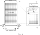
- the front surface area A1 of the display is a display area, which faces the forward direction of the electronic device 10, in the whole display area A3 of the electronic device 10 (or the display).
- the side surface (edge) area A2 of the display which is an area provided at one side or both sides of the front surface area A1, is a display area, which faces the side direction of the electronic device 10, or a display area, which faces the forward direction and the side direction of the electronic device 10, in an entire display area A3.
- the side surface area A2 may include a display area facing a backward direction of the electronic device 10.
- the side surface area A2 may have a curved surface shape or a flat surface shape.
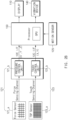
- the circuit component 100 includes a processor (e.g., including processing circuitry) 150, a memory 130, a touch sensor integrated chip (IC), a force sensor IC, and other circuit components 100'.
- the other circuit components 100' may include a printed circuit board P1, a processor (e.g., reference numeral 150 of FIG. 2A ) and a memory (e.g., reference numeral 130 of FIG. 2A ).
- the circuit components (com) will be described later with reference to FIGS. 2A and 2B .
- the housing members h1 to h6 may form an outer appearance of the electronic device 10 and may fix the circuit components to relevant positions.
- the housing members h1 to h6 may include a cover glass h1, a support member (dummy embo) h2, a metal bracket h3, a fixing member h4, a rear case h5, and a back cover h6.
- a printed circuit board (e.g., a memory, a processor, or the like) having the other circuit components 100' mounted on or accommodated in the PCB may be interposed between the metal bracket h3 and the rear case h5.
- the back cover h6 may be attached to an outer surface of the rear case h5.
- the back cover h6 may form an outer back surface of the electronic device 10.
- the back cover h6 may be formed of a polymer material or may be formed of metal or a ceramic material. Since the cover glass h1 is formed on a front outer surface of the electronic device 10, the electronic device 10 is formed to have a glass-type outer appearance by the cover glass h1 and the back cover h6.
- the above-described configuration of the housing members h1 to h6 of the electronic device 10 is provided for an illustrative purpose of explaining the arrangement relation between the touch sensor 123 and the force sensor 121.
- the housing and the housing members h1 to h6 of the electronic device 10 according to an embodiment disclosed in the present disclosure may have various configurations.
- the sensor module 120 includes various sensor circuitry, such as, for example, the touch sensor 123, the force sensor 121, and a motion sensor 125.
- various sensor circuitry such as, for example, the touch sensor 123, the force sensor 121, and a motion sensor 125.
- the above sensors will be described in greater detail below with reference to FIGS. 3A and 3B .
- the touch sensor 123 may include a touch panel 123_a and a touch control unit (e.g., including touch control circuitry) 123_b (see, e.g., FIG 2B ).
- the touch panel 123_a may be disposed or included above (or under) the side surface area A2 and the front surface area A1 of the display 110.
- the touch panel 123_a may be present separately from the display 110 and may be configured integrally with the display 110.
- the touch control unit 123_b may include various touch control circuitry and sense the variation in capacitance and touch coordinates corresponding to an approach, a touch, or a grip of a user to the touch panel 123_a based on a signal received from the touch panel 123_a.
- the touch control unit 123_b may sense touch coordinates (x, y) of the user by distinguishing the side surface area A2 and the front surface area A1. According to an embodiment, the touch control unit 123_b may control at least one of a portion of the touch panel 123_a disposed in the side surface area A2 or the front surface area A1 in terms of a sensing period, a sensitivity, and an activation/deactivation state. According to an embodiment, the touch control unit 123_b may communicate with the processor 150 through, for example, an I2C interface.
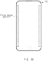
- the force sensor 121 may be included under the side surface area A2 of the display 110.
- the force sensor 121 may calculate the pressure to the side surface area A2 and a sensing position (x', y', and z) to the side surface area A2.
- the force sensor 121 may communicate with the processor 150 through, for example, an I2C interface.
- force sensors 121 are positioned at both sides of the electronic device 10.
- a force sensor pattern for pressure sensing may be positioned at an area other than the top or the bottom of the electronic device 10 in which a main antenna or a sub-antenna is present.
- the force sensor 121 may rarely affect antenna performance in an antenna area and may provide the convenience for the user in manipulating the side key.
- the force sensor 121 may be included throughout the whole area under the display 110 depending on the form in which the display 110 is implemented.
- the processor 150 may be configured to distinguish the front surface area A1 of the display 110 and the side surface areas A2 of the display 110.
- the motion sensor 125 senses the motion of the electronic device 10.
- the motion sensor 125 may be at least one of an acceleration sensor or a terrestrial magnetism sensor, or the like, but is not limited thereto.
- an example that the motion sensor 125 is the acceleration sensor will be described.
- the memory 130 may be a volatile memory (e.g., a random access memory (RAM), or the like), a non-volatile memory (e.g., a read-only memory (ROM), a flash memory, or the like), or any combination thereof.
- the memory 130 may store instructions or data associated with at least one of other element(s) of the electronic device 10.
- the memory 130 may store an instruction for sensing an approach of a user to the display 110 and a user input into the display 110, for displaying a graphic object on the display 110, and for executing a function corresponding to the graphic object.
- the graphic object may include a side key image to be displayed on the side surface area A2 of the display 110. Although the graphic object is displayed on even the front surface area A1 of the display 110, the following description will be made regarding the example that the graphic object is a side key image.
- the processor 150 may include, for example, and without limitation, at least one of a dedicated processor, a central processing unit (CPU), an application processor (AP), a graphics processing unit (GPU), a micro-processor, an application specific integrated circuits (ASIC), or a field programmable gate array (FPGA), or may have a plurality of cores, or the like.
- the processor 150 may perform an arithmetic operation or data processing associated with control and/or communication of at least other elements of the electronic device 10.
- the processor 150 senses the approach of the user to the electronic device 10 or the display 110 using the touch sensor 123. For example, if the capacitance sensed by the touch sensor 123 due to the approach of the user is equal to or greater than a first threshold capacitance, the processor 150 may determine the user to be in an approach state to the electronic device 10. To this end, the processor 150 may continuously activate the touch sensor (e.g., a touch panel at the side surface area) to sense the touch to the side surface area A2. The details thereof will be described later with reference to FIGS. 4A to 4C .
- the touch sensor e.g., a touch panel at the side surface area
- the processor 150 is configured to sense the grip of the user on the display 110 after sensing the approach of the user.
- the processor 150 may sense the grip of the user as the processor 150 senses the variation in the capacitance at both sides of the display 110 depending on the grip of the user.
- the processor 150 may determine whether the capacitance sensed by the touch sensor 123 belongs to a specified capacitance range to distinguish between the grip (or a touch) of the user and a touch by another component, for example, a holder of the electronic device 10.
- the processor 150 may sense a first user input into the side surface area A2 using the force sensor 121 in a grip state of the user. For example, the processor 150 may determine the first user input to occur if pressure sensed during the grip of the user belongs to a first specified range.
- the first specified range may be, for example, a pressure range of first threshold pressure or more.
- the first threshold pressure may be determined by an experiment of detecting a pressure value corresponding to the user input.
- the processor 150 may determine a position of at least one position on which the graphic object is to be displayed, if sensing the first user input. For example, the processor 150 may determine, as display positions of the graphic object, a position of the side surface area A2, in which the first user input is sensed, and a position of at least a portion of the front surface area A1 in the proximity of the sensed position. Therefore, according to an embodiment, as the graphic object is displayed on the side surface area A2 and the front surface area A1 of the display 110, the graphic object may be prevented from being hidden due to the grip of the user.
- the processor 150 determines whether the sensed first user input is a valid user input.
- the valid user input may be a user input made when the user holds the electronic device 10 at a specific angle to view the display 110.
- the processor 150 determines the validity of the first user input using the motion sensor 125 if sensing pressure belonging to the first specified range during the grip of the user.
- the processor 150 determines the variation in the acceleration of the electronic device 10 by using the motion sensor 125 (e.g., an acceleration sensor) and may determine the variation in the angle of the electronic device 10 based on the variation in the acceleration of the electronic device 10.
- the processor 150 may determine the first user input to be the valid user input. Therefore, according to an embodiment, the state of the user moving while viewing the display 110 (using the electronic device 10) may be distinguished from the state of the user carrying the electronic device 10 without using the electronic device 10.
- the processor 150 may sense a left hand grip state of the user and a right hand grip state of the user using the touch sensor 123.
- the processor 150 may differently determine the position of the at least one point in the left hand grip state of the user and the right hand grip state of the user.
- the processor 150 may determine the position of a power key object to be at a left side in which the thumb of the user is positioned and may determine the position of a volume up/down key object to be at a right side in which fingers of the user other than the thumb of the user are positioned, in the left hand grip state of the user.
- the processor 150 may determine the position of the power key object to be at the right side in which the thumb of the user is positioned and may determine the position of the volume up/down key object to be at the left side in which the fingers of the user other than the thumb of the user are positioned, in the right hand grip state of the user.
- the graphic object may be displayed at a position at which both of a left-handed user and a right-handed user are able to easily manipulate the graphic object.
- the processor 150 may continuously display a graphic object on the side surface area A2 until a first specified condition is satisfied after displaying the graphic object.
- the first specified condition may refer to that touches of a user are released from all touch areas of the display 110. Therefore, according to an embodiment, the user may release the touch to one of touch areas and then touch to the touch area again to manipulate one of a plurality of graphic objects. In this case, since remaining touch areas are maintained in a touch state, the processor 150 may continuously display the graphic object.
- the processor 150 may display the graphic object and may erase the graphic object displayed on the side surface area A2 if the first specified condition is satisfied.
- the processor 150 may initialize the determined position of the at least one point if the graphic object is erased from the side surface area A2.
- the position of the graphic object may be changed depending on the touch area of the user. Accordingly, the graphic object may be displayed at a position that the user is easily able to manipulate the graphic object.
- the processor 150 may provide a haptic feedback for the user using the vibration device 140.
- the processor 150 may generate vibration corresponding to the graphic object by using the vibration device 140 to provide a touch feel of a real physical key for the user.
- the processor 150 may vibrate the vibration device 140 at a first frequency to provide a touch feel of a real key for the user.
- the processor 150 may vibrate the vibration device 140 at a second frequency to provide a click feel of a real key.
- the processor 150 may determine the position of the at least one point to be the same position in both of the left hand grip of the user and the right hand grip of the user. In detail, the processor 150 may determine the position of the at least one point to be the same position in both of the left hand grip of the user and the right hand grip of the user if first settings is made through the sensor module 120.
- the first settings may be, for example, made through the manipulation of a first menu for setting the position of the at least one point to the same position regardless of the type of hands (e.g., a left hand or a right hand) which grip the electronic device 10.
- the processor 150 may determine whether to make the first settings by determining the manipulation state of the first menu based on touch coordinates of at least one of the front surface area A1 or the side surface area A2.
- the processor 150 may fix the position of the graphic object without changing the position of the graphic object if making second settings through the sensor module 120.
- the second settings may be made through the manipulation of a second menu for fixing the position of the graphic object regardless of the position in which the user input is sensed.
- the processor 150 may determine whether to make the second settings by determining the manipulation state of a functional menu based on the coordinates of a touch of the user to at least one of the front surface area A1 or the side surface area A2. Therefore, according to an embodiment, a curved surface may be seamlessly designed in the electronic device 10 having the display structure, and a side key object may be intuitively and intelligently provided for the user.
- the processor 150 may differently control the sensitivity to a touch panel (hereinafter, referred to as "first touch panel”), which is provided above (or under) the front surface area A1, and the sensitivity to a touch panel (hereinafter, referred to as “second touch panel”), which is provided above (or under) the side surface area A2, through the touch control unit 123_b.
- the touch control unit 123_b may be configured to differently control the sensitivity of the first touch panel and the sensitivity of the second touch panel.
- FIGS. 4A to 4C the details thereof will be described with reference to FIGS. 4A to 4C .
- FIG. 4A is a circuit diagram illustrating an example touch sensor, according to an example embodiment of the present disclosure
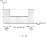
- FIG. 4B is a graph illustrating example driving signal strength sensed in each area of the touch sensor, according to an example embodiment of the present disclosure
- FIG. 4C is a diagram illustrating an example hovering area of the electronic device, according to an example embodiment of the present disclosure.
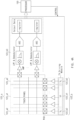
- the touch control unit 123_b may include a first transmission block 123_b1, a second transmission block 123_b2, and a plurality of reception blocks 123_b3.
- the first transmission block 123_b1 may be a block which transmits a signal to a first touch panel 123_a1 included above (or under) the front surface area A1.
- the second transmission block 123_b2 may be a block which transmits a signal to a second touch panel 123_a2 included above (or under) the side surface area A2.
- a plurality of first transmission block 123_b1 may be provided.
- the first transmission blocks 123_b1 may include a transmission block, which is provided in the side surface area A2 at a right side of the electronic device 10, and a transmission block which is provided in the side surface area A2 at a left side of the electronic device 10.
- the reception blocks 123_b3 may include at least one amplifier AMP, a low-pass filter LPF, a demodulator, an analog-digital modulator (ADC), and an output register.
- Each reception block 123_b3 may receive an analog signal corresponding to capacitance from each row of the touch panel 123_a connected to the reception block 123_b3 and may convert and output the analog signal to digital coordinates. Since those skilled in the art may obviously derive the configuration of the reception block 123_b3 from the configuration of the touch sensor 123, the details thereof will be omitted.
- the processor 150 may differently control the first touch panel 123_a1, which is provided above (or under) the front surface area A1, and the second touch panel 123_a2, which is provided above (or under) the side surface area A2, in terms of at least one of a signal sensitivity or activation/deactivation.
- the touch control unit 123_b may adjust the transmit power of the first touch panel 123_a1 to V1 and adjust the transmit power of the second touch panel 123_a2 to V2 (>V1).
- the strength of the transmit power V1 of the first touch panel 123_a1 may be set to strength sufficient to cover the range of a first hovering area.
- the strength of the transmit power V1 of the first touch panel 123_a1 may be set to strength sufficient to sense the approach of the user at a distance (first hovering area) of, for example, 1 cm or less from the front surface area A1, but is not limited thereto.
- the strength of the transmit power V2 of the second touch panel 123_a2 may be set to strength sufficient to cover the range of a second hovering area.
- the strength of the transmit power V2 of the second touch panel 123_a2 may be set to strength sufficient to sense the approach of the user at a distance (second hovering area) of, for example, 3cm or less from the side surface area A2, but is not limited thereto.
- the processor 150 may set a signal transmission period for the second touch panel 123_a2 to a first period if failing to sense the approach of the user using the second touch panel 123_a2 (or before sensing the approach of the user by using the second touch panel 123_a2). After sensing the approach of the user, the processor 150 may set a signal transmission period for the second touch panel 123_a2 to a second period (> the first period)
- the processor 150 may deactivate the first transmission block 123_b1, which transmits a signal to the first touch panel 123_a1) if failing to sense the approach of the user by using the second touch panel 123_a2. After sensing the approach of the user using the second touch panel 123_a2, the processor 150 may activate the first transmission block 123_b1. As described above, according to an embodiment, the approach of the user may be easily sensed, and the power consumption for sensing the touch of the user may be reduced.
- the touch sensor 123 may include a plurality of touch sensors.
- the touch sensor 123 may include a first touch sensor including the first touch panel 123_a1 and the first touch control unit (not illustrated) and a second touch sensor including the second touch panel 123_a2 and the second touch control unit 123_b.
- FIG. 5 is a diagram illustrating an example manner of determining a position of a graphic object depending on a left hand/ right hand grip of a user, according to an example embodiment of the present disclosure.
- the thumb of the user may touch a first touch area 511 positioned at an upper left portion of the display 110, and remaining fingers of the user other than the thumb may touch a second touch area 512 positioned at a lower right portion of the display 110.
- the processor 150 may determine the position of a power key object based on the first touch area 511 positioned at the upper left portion of the display 110 and determine the position of a volume control key object based on the second touch area 512 positioned at the lower right portion of the display 110, in state 510.
- the processor 150 may determine the position of the at least one point by taking into consideration the positions of the fingers of the user on the second touch area 512 on which the volume control key object is displayed. For example, in the case that the first user input is sensed in a plurality of positions of the second touch area 512, the processor 150 may determine two upper positions among the plurality of positions to be positions of a plurality of points on which the volume control key object is to be displayed.
- the thumb of the user may touch a fifth touch area 515 positioned at an upper right portion of the display 110, and remaining fingers of the user other than the thumb may touch a sixth touch area 516 positioned at a lower left portion of the display 110.
- the processor 150 may determine the position of a power key object based on the fifth touch area 515 positioned at the upper right portion of the display 110 and determine the position of a volume control key object based on the sixth touch area 516 positioned at the lower left portion of the display 110, in state 520.
- the graphic object may be displayed on a position in which the user is able to more easily manipulate (touch) the graphic object.
- FIG. 6 is a diagram illustrating an example display position of a graphic object, according to an example embodiment of the present disclosure.
- the processor 150 may determine the position of the at least one point on which the graphic object is to be displayed based on at least one of the touch area touched by the user or the sensing position of the first user input. For example, the processor 150 may determine the display position of the graphic object to include at least portions of a first position A61 of the side surface area A2, at which the first user input is detected, and a second position A62 of the front surface area A1, which is in the proximity of the first position A61 and has a specified area. The specified area may be set to an area corresponding to the first position A61. For another example, the processor 150 may determine a position A63 of one side of the front surface area A1, which is in the proximity of the first position A61 of the side surface area A2, to be the position of the at least one point.
- the graphic object may be prevented from being hidden due to the grip by the user.
- FIG. 7 is a diagram illustrating an example manner of manipulating a graphic object, according to an example embodiment of the present disclosure.
- the processor 150 may determine a graphic object, which is selected from two graphic objects, based on a sliding direction of a user at a right side of the display 110. For example, if the hand of the user moves (slides) downward in the state that the touch by the hand of the user is not released from one side of the display 110 displaying two graphic objects, the processor 150 may determine an upper graphic object to be selected from two graphic objects. In this case, the processor 150 may repeatedly execute a first function by the number of times of sliding downward while ignoring sliding upward until the second user input is detected again.
- the processor 150 may determine whether to change the sliding direction, if sensing a second user input while sensing sliding downward. Thereafter, if the user slides upward, the processor 150 may determine a lower graphic object to be selected and may repeatedly execute a second function corresponding to the lower graphic object by the number of times of sliding upward.
- FIG. 8 is a flowchart illustrating a method of displaying the graphic object (a side key object), according to an example embodiment of the present disclosure.
- the processor 150 monitors the approach (hovering) of the user to the side surface area A2 of the display, in operation 810.
- the processor 150 may monitor the approach state of the user by sensing the variation in capacitance using the second touch panel 123_a2 included in an upper portion (or a lower portion) of the side surface area A2.
- the processor 150 may determine the user to approach the side surface area A2 of the display, if sensing at least a capacitance specified for the approach of the user to the side surface area A2.
- the processor 150 may increase the sensitivity of the second touch panel 123_a2 included above (or under) the side surface area A2. For example, the processor 150 may reduce the sensing period of the second touch panel 123_a2. If sensing the approach of the user to the side surface area A2 in operation 820, the processor 150 activates the force sensor 121 and the motion sensor 125.
- the processor 150 senses pressure using the force sensor 121 and determine whether the sensed pressure is within the first specified range, in operation 830.
- the first specified range may be, for example, a pressure range of the first threshold pressure or more. If the sensed pressure is not determined to belong to the first specified range, the processor 150 may ignore the sensed pressure in operation 890.
- the processor 150 determines whether the sensed pressure is a valid pressure, by using the motion sensor 125, in operation 840. For example, the processor 150 may determine the variation in the acceleration of the display 110 by using the motion sensor 125 and may determine, based on the variation in the acceleration of the display 110, whether the display 110 is maintained at a specific angle. If determining the display 110 to be maintained at the specific angle, the processor 150 may determine the sensed pressure to be the valid pressure. Meanwhile, if the failing to determine the sensed pressure to be the valid pressure, the processor 150 may ignore the sensed pressure in operation 890.
- the processor 150 determines the position of the at least one point in operation 850. According to an embodiment, the processor 150 determines, based on the sensed touch area, whether the grip state of the user is a right hand grip state or a left hand grip state and may differently determine the position of the at least a point in the right hand grip state and in the left hand grip state.
- the processor 150 displays at least one graphic object (e.g., a side key object) on the determined position in the side surface area A2 of the display 110 in operation 860.
- the processor 150 may prepare for a graphic object, which is to be displayed, in operation 820 to operation 860.
- the processor 150 may differently display the graphic object in the right hand grip state and the left hand grip state.
- the processor 150 may determine whether pressure within the second specified range is sensed to one of graphic objects in operation 870.
- the second specified range may be, for example, a pressure range of the second threshold pressure (> the first threshold pressure) or more.
- the processor 150 may execute a function corresponding to the graphic object to, which the pressure belonging to the second specified range is sensed, in operation 880.
- the processor 150 may determine whether to initialize the determined position and to erase the displayed graphic object as illustrated in FIG. 9 , in the state that the graphic object is displayed on the display 110, in operation 830 to operation 880.
- a side key object may be provided to a position of the side surface area A2 of the display 110 corresponding to the position of the hand of the user.
- FIG. 9 is a flowchart illustrating an example manner of initializing the graphic object, according to an example embodiment of the present disclosure.
- the processor 150 may determine whether the touch of the user to at least one point of the side surface area A2 is maintained using the touch sensor 123 in the state that the graphic object is displayed, in operation 910.
- the processor 150 may erase the displayed graphic object in operation 920.
- the processor 150 may initialize the determined position of the at least one point in operation 920.
- the side key object may be fluidly or variably displayed.
- the processor 150 may continuously display the graphic object in operation 930. For example, the user may release the touch to one of touch areas of the display 110 and then touch to the touch area again to manipulate one of a plurality of graphic objects. In this case, since a touch to any one of the touch areas is maintained, the processor 150 may continuously display the graphic object.
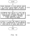
- FIG. 10 is a flowchart illustrating an example method of displaying an object, according to an example embodiment of the present disclosure.
- a processor may sense pressure to a side surface area of a display using a sensor included under the side surface area of the display, in operation 1010.
- the processor 150 may determine whether the sensed pressure is within a first specified range, in operation 1020.
- the processor 150 may determine a position of at least one point of the side surface area if the sensed pressure belongs to the first specified range, in operation 1020.
- the processor 150 may display at least one graphic object on an area corresponding to the determined position of the at least one point in operation 1030.
- an electronic device includes a display including a front surface area and a side surface area disposed in at least one side of the front surface area; a first sensor included under the side surface area and configured to sense pressure applied to the side surface area; and a processor operatively connected with the display and the first sensor, wherein the processor is configured to determine a position of at least one point of the side surface area corresponding to a sensed pressure, if the sensed pressure using the first sensor is within a first specified range; and the processor is further configured to cause the electronic device to display at least one graphic object on an area corresponding to the determined position.
- the electronic device further includes a second sensor configured to sense a grip on the display, wherein the processor is configured to sense a left hand grip and/or a right hand grip using the second sensor; and the processor is further configured to differently determine the position of the at least one point based on sensing the left hand grip and the right hand grip.
- the electronic device further includes a second sensor configured to sense a touch to the display, wherein the processor is configured to determine the position of the at least one point if the sensed pressure is withing the first specified range in a state that the touch is sensed using the second sensor.
- the processor may be configured to sense an approach (hovering proximity) to the display or the touch to the display using the second sensor; the processor may be further configured to activate the first sensor if sensing the approach or the touch; and the processor may be further configured to deactivate the first sensor if failing to sense the approach or the touch.
- the processor may be configured to determine, as the position of the at least one point, a position including a first position, in which pressure within the first specified range is sensed and a portion of the front surface area close to the first position.
- the processor may be configured to execute a first function corresponding to the at least one graphic object if the sensed pressure is within a second specified range in the area, on which the at least one graphic object is displayed, in a state that the touch is sensed.
- the processor may be configured to erase the at least one graphic object and initialize the position of the at least one point if sensing release of a touch to the side surface area using the second sensor.
- the electronic device further includes a motion sensor, wherein the processor is configured to determine a use situation of the display based on variation in an angle of the display determined using the motion sensor; and the processor is further configured to determine the position of the at least one point if the display is being used.
- the electronic device further includes a second sensor and a first touch panel disposed under the front surface area and a second touch panel disposed under the side surface area, wherein the processor is configured to allow the second sensor to increase a sensitivity of the second touch panel to be greater than a sensitivity of the first touch panel.
- the processor may be configured to sense a state of an approach (hovering proximity) using the second sensor; and the processor may be further configured to increase a signal transmission period of the second touch panel after sensing the approach of the user to be greater than a signal transmission period before sensing the approach of the user.
- the processor may be configured to sense a state of an approach (hovering proximity) using the second sensor; the processor may be further configured to deactivate a first transmission block, which is configured to transmit a signal to the first touch panel, if failing to sense the approach of the user; and the processor may be further configured to activate the first transmission block after sensing the approach of the user.
- a method of displaying an object by an electronic device includes sensing pressure to a side surface area of a display using a sensor included under the side surface area; determining a position of at least one point of the side surface area corresponding to the sensed pressure, if the sensed pressure is within a first specified range; and displaying at least one graphic object on one area corresponding to the determined position of the at least one point.
- the method further includes determining whether the sensed pressure is within a second specified range in the at least one area, on which the at least one graphic object is displayed; and executing a first function corresponding to the at least one graphic object if the sensed pressure is within the second specified range.
- the method further includes monitoring release of a touch to the side surface area in a state that the at least one graphic object is displayed; erasing the at least one graphic object displayed on the display if the release of the touch is sensed; and initializing the position of the at least one point.
- the method further includes sensing an approach (hovering proximity) to the display or a touch to the display; and activating an element which senses the pressure if the approach or the touch is sensed.
- the determining of the position of the at least one point includes determining a use situation of the display based on variation in an angle of the display; and determining the position of the at least one point if the display is being used.
- the method further includes sensing an approach (hovering proximity), wherein the increasing of the sensitivity of the first touch panel includes increasing a signal transmission period of the second touch panel after sensing the approach of the user to a signal transmission period greater than the signal transmission period before sensing the approach of the user.
- FIG. 11 is a block diagram illustrating an example electronic device in a network environment according to various example embodiments of the present disclosure.
- the electronic device may include at least one of, for example, televisions (TVs), digital versatile disc (DVD) players, audios, audio accessory devices (e.g., a speaker, a headphone, or a headset), a refrigerator, an air conditioner, a cleaner, an oven, a microwave oven, a washing machine, an air cleaner, a set-top box, a home automation control panel, a security control panel, a game console, an electronic dictionary, an electronic key, a camcorder, or an electronic picture frame, or the like, but is not limited thereto.
- TVs televisions
- DVD digital versatile disc
- audio accessory devices e.g., a speaker, a headphone, or a headset
- a refrigerator e.g., a refrigerator, an air conditioner, a cleaner, an oven, a microwave oven, a washing machine, an air cleaner, a set-top box, a home automation control panel, a security control panel, a game console, an electronic dictionary, an electronic key, a camcorder,
- the electronic device is not limited to the above-described devices.
- the electronic device may complexly provide functions of multiple devices.
- the term "user" used herein may refer to a person who uses the electronic device or may refer to a device (e.g., an artificial intelligence electronic device) that uses the electronic device.
- the electronic device 1101 may communicate with an electronic device 1102 through local wireless communication 1198 or may communication with an electronic device 1104 or a server 1108 through a network 1199. According an embodiment, the electronic device 1101 may communicate with the electronic device 1104 through the server 1108.
- the electronic device 1101 may include a bus 1110, a processor 1120 (e.g., at least one processor and/or processing circuitry), a memory 1130, an input device 1150 (e.g., including input circuitry, such as, for example, and without limitation, a micro-phone or a mouse), a display 1160, an audio module (e.g., including audio circuitry) 1170, a sensor module 1176, an interface (e.g., including interface circuitry) 1177, a haptic module (e.g., including haptic circuitry) 1179, a camera module 1180, a power management module 1188, a battery 1189, a communication module (e.g., including communication circuitry) 1190, and a subscriber identification module 1196.
- the electronic device 1101 may not include at least one (e.g., the display 1160 or the camera module 1180) of the above-described elements or may further include other element(s).
- the bus 1110 may interconnect the above-described elements 1120 to 1190 and may include a circuit for conveying signals (e.g., a control message or data) between the above-described elements.
- signals e.g., a control message or data
- the processor 1120 may include various processing circuitry, such as, for example, and without limitation, one or more of a dedicated processor, a central processing unit (CPU), an application processor (application), a graphic processing unit (GPU), a camera image signal processor (ISP) of a camera or a communication processor (CP), or the like.
- the processor 1120 may be implemented with a system on chip (Soc) or a system in package (SiP).
- Soc system on chip
- SiP system in package
- the processor 1120 may drive an operating system (OS) or an application to control at least one of another element (e.g., hardware or software element) connected to the processor 1120 and may process and compute various data.
- OS operating system
- another element e.g., hardware or software element
- the memory 1130 may include, for example, a volatile memory 1132 or a nonvolatile memory 1134.
- the volatile memory 1132 may include, for example, a random access memory (RAM) (e.g., a dynamic random access memory (DRAM), a static RAM (SRAM), or a synchronous dynamic RAM (SDRAM)).
- the nonvolatile memory 1134 may include, for example, one time programmable read-only memory (OTPROM), programmable read-only memory (PROM), an erasable programmable read-only memory (EPROM), an electrically erasable programmable read-only memory (EEPROM), a mask ROM, a flash ROM, a flash memory, a hard drive, or a solid-state drive (SSD).
- OTPROM one time programmable read-only memory
- PROM programmable read-only memory
- EPROM erasable programmable read-only memory
- EEPROM electrically erasable programmable read-only memory
- nonvolatile memory 1134 may be configured in the form of an internal memory 1136 or the form of an external memory 1138 which is available through connection only if necessary, according to the connection forms of the electronic device 1101.
- the external memory 1138 may further include a flash drive such as compact flash (CF), secure digital (SD), micro secure digital (micro-SD), mini secure digital (mini-SD), extreme digital (xD), a multimedia card (MMC), or a memory stick.
- the external memory 1138 may be operatively or physically connected with the electronic device 1101 in a wired manner (e.g., a cable or a universal serial bus (USB)) or a wireless (e.g., Bluetooth (BT)) manner.
- a wired manner e.g., a cable or a universal serial bus (USB)
- BT wireless
- the memory 1130 may store, for example, at least one different software element, such as an instruction or data associated with the program 1140, of the electronic device 1101.
- the program 1140 may include, for example, a kernel 1141, a library 1143, an application framework 1145 or an application program (interchangeably, "application") 1147.
- the input device 1150 may include various input circuitry, such as, for example, and without limitation, a microphone, a mouse, or a keyboard, or the like.
- the keyboard may include a keyboard physically connected or a keyboard virtually displayed through the display 1160.
- the display 1160 may include a display, a hologram device or a projector, and a control circuit to control a relevant device.
- the screen may include, for example, a liquid crystal display (LCD), a light emitting diode (LED) display, an organic LED (OLED) display, a plastic OLED (POLED), a microelectromechanical systems (MEMS) display, or an electronic paper display, or the like, but is not limited thereto.
- the display may be flexibly, transparently, or wearably implemented.
- the display may include a touch circuitry, which is able to detect a user's touch input such as a gesture input, a proximity input, or a hovering input or a pressure sensor (interchangeably, a force sensor) which is able to measure the intensity of the pressure by the touch.
- the touch circuit or the pressure sensor may be implemented integrally with the display or may be implemented with at least one sensor separately from the display.
- the hologram device may show a stereoscopic image in a space using interference of light.
- the projector may project light onto a screen to display an image.
- the screen may be located inside or outside the electronic device 1101.
- the audio module 1170 may include various audio circuitry and convert, for example, from a sound into an electrical signal or from an electrical signal into the sound. According to an embodiment, the audio module 1170 may acquire sound through the input device 1150 (e.g., a microphone) or may output sound through an output device (not illustrated) (e.g., a speaker or a receiver) included in the electronic device 1101, an external electronic device (e.g., the electronic device 1102 (e.g., a wireless speaker or a wireless headphone)) or an electronic device 1106 (e.g., a wired speaker or a wired headphone)connected with the electronic device 1101
- the input device 1150 e.g., a microphone
- an output device not illustrated
- an external electronic device e.g., the electronic device 1102 (e.g., a wireless speaker or a wireless headphone)
- an electronic device 1106 e.g., a wired speaker or a wired headphone
- the sensor module 1176 may measure or detect, for example, an internal operating state (e.g., power or temperature) or an external environment state (e.g., an altitude, a humidity, or brightness) of the electronic device 1101 to generate an electrical signal or a data value corresponding to the information of the measured state or the detected state.
- an internal operating state e.g., power or temperature
- an external environment state e.g., an altitude, a humidity, or brightness
- the sensor module 1176 may include, for example, and without limitation, at least one of a gesture sensor, a gyro sensor, a barometric pressure sensor, a magnetic sensor, an acceleration sensor, a grip sensor, a proximity sensor, a color sensor (e.g., a red, green, blue (RGB) sensor), an infrared sensor, a biometric sensor (e.g., an iris sensor, a fingerprint senor, a heartbeat rate monitoring (HRM) sensor, an e-nose sensor, an electromyography (EMG) sensor, an electroencephalogram (EEG) sensor, an electrocardiogram (ECG) sensor, a temperature sensor, a humidity sensor, an illuminance sensor or an UV sensor, or the like.
- a gesture sensor e.g., a gyro sensor, a barometric pressure sensor, a magnetic sensor, an acceleration sensor, a grip sensor, a proximity sensor, a color sensor (e.g., a red, green, blue
- the sensor module 1176 may further include a control circuit for controlling at least one or more sensors included therein.
- the sensor module 1176 may be controlled by using the processor 1120 or a processor (e.g., a sensor hub) separate from the processor 1120.
- a processor e.g., a sensor hub
- the separate processor may operate without awakening the processor 1120 to control at least a portion of the operation or the state of the sensor module 1176.
- the haptic module 1179 may include various circuitry and convert an electrical signal into mechanical stimulation (e.g., vibration or motion) or into electrical stimulation. For example, the haptic module 1179 may apply tactile or kinesthetic stimulation to a user.
- the haptic module 1179 may include, for example, a motor, a piezoelectric element, or an electric stimulator.
- the camera module 1180 may capture, for example, a still image and a moving picture.
- the camera module 1180 may include at least one lens (e.g., a wide-angle lens and a telephoto lens, or a front lens and a rear lens), an image sensor, an image signal processor (ISP), or a flash (e.g., a light emitting diode or a xenon lamp).
- a lens e.g., a wide-angle lens and a telephoto lens, or a front lens and a rear lens
- ISP image signal processor
- flash e.g., a light emitting diode or a xenon lamp
- the power management module 1188 may include various circuitry to manage the power of the electronic device 1101, may constitute at least a portion of a power management integrated circuit (PMIC).
- PMIC power management integrated circuit
- the battery 1189 may include a primary cell, a secondary cell, or a fuel cell and may be recharged by an external power source to supply power at least one element of the electronic device 1101.
- the communication module 1190 may include various communication circuitry and establish a communication channel between the electronic device 1101 and an external device (e.g., the first external electronic device 1102, the second external electronic device 1104, or the server 1108).
- the communication module 1190 may support wired communication or wireless communication through the established communication channel.
- the communication module 1190 may include a wireless communication module 1192 or a wired communication module 1194.
- the communication module 1190 may communicate with the external device (e.g., the first external electronic device 1102, the second external electronic device 1104 or the server 1108) through a first network 1198 (e.g.
- the wireless communication module 1192 may support, for example, cellular communication, local wireless communication, global navigation satellite system (GNSS) communication.
- the cellular communication may include, for example, long-term evolution (LTE), LTE Advance (LTE-A), code division multiple access (CMA), wideband CDMA (WCDMA), universal mobile telecommunications system (UMTS), wireless broadband (WiBro), or global system for mobile communications (GSM).
- the local wireless communication may include wireless fidelity (Wi-Fi), WiFi Direct, light fidelity, Bluetooth, Bluetooth low energy (BLE), Zigbee, near field communication (NFC), magnetic secure transmission (MST), radio frequency (RF), or a body area network (BAN).
- the GNSS may include at least one of a global positioning system (GPS), a global navigation satellite system (Glonass), Beidou Navigation Satellite System (Beidou) or Galileo, the European global satellite-based navigation system, or the like.
- GPS global positioning system
- Glonass global navigation satellite system
- Beidou Beidou Navigation Satellite System
- Galileo the European global satellite-based navigation system
- the wireless communication module 1192 may, for example, identify or authenticate the electronic device 1101 within a communication network using the subscriber identification module (e.g., a SIM card) 1196.
- the wireless communication module 1192 may include the processor 1120 (e.g., an application processor (AP) and a separate communication processor (CP).
- the communication processor may perform at least a portion of functions associated with at least one of elements 1110 to 1196 of the electronic device 1101 in substitute for the processor 1120 when the processor 1120 is in an inactive (sleep) state, and together with the processor 1120 when the processor 1120 is in an active state.
- the wireless communication module 1192 may include a plurality of communication modules, each supporting only a relevant communication scheme among cellular communication, short-range wireless communication, or a GNSS communication scheme.
- the wired communication module 1194 may include, for example, include a local area network (LAN) service, a power line communication, or a plain old telephone service (POTS).
- LAN local area network
- POTS plain old telephone service
- the first network 1198 may employ, for example, WiFi direct or Bluetooth for transmitting or receiving instructions or data through wireless direct connection between the electronic device 1101 and the first external electronic device 1102.
- the second network 1199 may include a telecommunication network (e.g., a computer network such as a LAN or a WAN, the Internet or a telephone network) for transmitting or receiving instructions or data between the electronic device 1101 and the second electronic device 1104.
- a telecommunication network e.g., a computer network such as a LAN or a WAN, the Internet or a telephone network
- the instructions or the data may be transmitted or received between the electronic device 1101 and the second external electronic device 1104 through the server 1108 connected with the second network.
- Each of the external first and second external electronic devices 1102 and 1104 may be a device of which the type is different from or the same as that of the electronic device 1101.
- all or a part of operations that the electronic device (1101 will perform may be executed by another or a plurality of electronic devices (e.g., the electronic devices 1102 and 1104 or the server 1108.
- the electronic device 1101 may not perform the function or the service internally, but may alternatively or additionally transmit requests for at least a part of a function associated with the electronic device 1101 to another device (e.g., the electronic device 1102 or 1104 or the server 1108).
- the another electronic device e.g., the electronic device 1102 or 1104 or the server 1108, may execute the requested function or additional function and may transmit the execution result to the electronic device 1101.
- the electronic device 1101 may provide the requested function or service using the received result or may additionally process the received result to provide the requested function or service.
- cloud computing, distributed computing, or client-server computing may be used.
- module as used in the present disclosure may refer, for example, to a unit including one or more combinations of hardware, software and firmware.
- the term “module” may be interchangeably used with the terms “unit”, “logic”, “logical block”, “component” and “circuit”.
- the “module” may be a minimum unit of an integrated component or may be a part thereof.
- the “module” may be a minimum unit for performing one or more functions or a part thereof.
- the “module” may be implemented mechanically or electronically.
- the "module” may include at least one of a dedicated processor, a CPU, an application-specific IC (ASIC) chip, a field-programmable gate array (FPGA), and a programmable-logic device for performing some operations, or the like, which are known or will be developed.
- ASIC application-specific IC
- FPGA field-programmable gate array
- At least a part of an apparatus (e.g., modules or functions thereof) or a method (e.g., operations) according to an embodiment of the present disclosure may be, for example, implemented by instructions stored in a computer-readable storage media in the form of a program module.
- the instruction when executed by a processor 1120, may cause the one or more processors to perform a function corresponding to the instruction.
- the computer-readable storage media for example, may be the memory 1130.
- a computer-readable recording medium may include a hard disk, a floppy disk, a magnetic media (e.g., a magnetic tape), an optical media (e.g., a compact disc read only memory (CD-ROM) and a digital versatile disc (DVD), a magneto-optical media (e.g., a floptical disk)), and hardware devices (e.g., a read only memory (ROM), a random access memory (RAM), or a flash memory).
- a program instruction may include not only a mechanical code such as generated by a compiler but also a high-level language code executable on a computer using an interpreter.
- the above hardware unit may be configured to operate via one or more software modules for performing an operation according to an embodiment of the present disclosure, and vice versa.
Landscapes
- Engineering & Computer Science (AREA)
- Theoretical Computer Science (AREA)
- General Engineering & Computer Science (AREA)
- Human Computer Interaction (AREA)
- Physics & Mathematics (AREA)
- General Physics & Mathematics (AREA)
- Computer Hardware Design (AREA)
- Computer Graphics (AREA)
- Signal Processing (AREA)
- User Interface Of Digital Computer (AREA)
- Position Input By Displaying (AREA)
- Computer Networks & Wireless Communication (AREA)
Claims (11)
- Elektronische Vorrichtung (10), die Folgendes umfasst:ein Display (110), das eine Vorderfläche und eine Seitenfläche enthält, die an mindestens einer Seite der Vorderfläche angeordnet ist, wobei die Vorderfläche in eine Vorwärtsrichtung der elektronischen Vorrichtung weist und die Seitenfläche in eine Seitenrichtung, in die Vorwärtsrichtung und in die Seitenrichtung oder in eine Rückwärtsrichtung der elektronischen Vorrichtung weist;einen ersten Sensor (121), der unter der Seitenfläche (A2) angeordnet ist und so konfiguriert ist, dass er einen auf zumindest einen Teil der Seitenfläche (A2) ausgeübten Druck erfasst;einen zweiten Sensor (123), der so konfiguriert ist, dass er eine Eingabe auf dem Display erfasst, wobei die Eingabe eine schwebende Eingabe enthält;einen Bewegungssensor (125); undeinen Prozessor (150), der mit dem Display (110), dem ersten Sensor, dem zweiten Sensor und dem Bewegungssensor operativ verbunden ist,wobei der Prozessor (150) zu Folgendem konfiguriert ist:Identifizieren (810, 820) der Eingabe auf dem Display über den zweiten Sensor (123),als Antwort auf die Eingabe auf dem Display, Aktivieren des ersten Sensors (121) und des Bewegungssensors (125),nach der Aktivierung des ersten Sensors (121), Identifizieren eines Drucks der Eingabe über den ersten Sensor (121),wenn (830) der Druck der Eingabe innerhalb eines ersten angegebenen Bereichs liegt, Bestimmen (840), ob der Druck ein gültiger Druck ist, basierend auf einer Variation einer Beschleunigung des Displays über den Bewegungssensor (125),wenn der Druck der Eingabe ein gültiger Druck ist, Bestimmen, ob ein Griff der rechten Hand oder ein Griff der linken Hand zu dem Druck geführt hat, und Bestimmen (850) einer ersten Position (x', y', z') von mindestens einem Punkt der Seitenfläche (A2), die dem erfassten Druck entspricht, undAnzeigen (860) mindestens eines grafischen Objekts auf einer Fläche, die die bestimmte erste Position enthält, basierend auf der Bestimmung, ob der Druck durch den Griff der rechten Hand oder den Griff der linken Hand verursacht wurde,wobei das grafische Objekt ein Seitentastenobjekt ist, das ein Power-Tastenobjekt (k1) und/oder ein Volumentastenobjekt (k2) umfasst.
- Elektronische Vorrichtung nach Anspruch 1, die ferner Folgendes umfasst:
wobei der zweite Sensor (123) ferner so konfiguriert ist, dass er einen Griff auf dem Display erfasst, wobei der Prozessor (150) zu Folgendem konfiguriert ist:Erfassen des Griffs der linken Hand und/oder des Griffs der rechten Hand unter Verwendung des zweiten Sensors (123); undunterschiedliches Bestimmen der Position des mindestens einen Punktes basierend auf dem Erfassen des Griffs der linken Hand und/oder des Griffs der rechten Hand. - Elektronische Vorrichtung nach Anspruch 1, wobei der Prozessor ferner zu Folgendem konfiguriert ist:Bestimmen, als Position des mindestens einen Punktes, einer Position, die die erste Position (A61) enthält, in der ein Druck innerhalb des ersten angegebenen Bereichs erfasst wird und eines Teils (A62, A63, A1) der Vorderseite innerhalb einer vorbestimmten Distanz zu der ersten Position.
- Elektronische Vorrichtung nach Anspruch 1, wobei der Prozessor ferner zu Folgendem konfiguriert ist:
Ausführen (880) einer ersten Funktion, die dem mindestens einen grafischen Objekt entspricht, wenn (870) der erfasste Druck innerhalb eines zweiten angegebenen Bereichs in dem Bereich liegt, auf dem das mindestens eine grafische Objekt angezeigt wird, in einem Zustand, in dem die Berührung erfasst wird. - Elektronische Vorrichtung nach Anspruch 1, wobei der Prozessor zu Folgendem konfiguriert ist:
Löschen (920) des mindestens einen grafischen Objekts und Initialisieren der Position des mindestens einen Punktes, wenn die Freigabe einer Berührung der Seitenfläche unter Verwendung des zweiten Sensors erfasst wird. - Elektronische Vorrichtung nach Anspruch 1, die ferner Folgendes umfasst:wobei der zweite Sensor (123) ein erstes Touchpanel (123_a1), das unter der Vorderfläche (A1) angeordnet ist, und ein zweites Touchpanel (123_a2) enthält, das unter der Seitenfläche (A2) angeordnet ist,wobei der Prozessor zu Folgendem konfiguriert ist:
Ermöglichen, dass der zweite Sensor eine Empfindlichkeit des zweiten Touchpanels so erhöht, dass sie höher als eine Empfindlichkeit des ersten Touchpanels ist. - Elektronische Vorrichtung nach Anspruch 6, wobei der Prozessor ferner zu Folgendem konfiguriert ist:Erfassen eines Zustands einer schwebenden Nähe unter Verwendung des zweiten Sensors; undErhöhen einer Signalübertragungsperiode des zweiten Touchpanels nach dem Erfassen der schwebenden Nähe, so dass sie größer als eine Signalübertragungsperiode vor dem Erfassen der schwebenden Nähe ist.
- Elektronische Vorrichtung nach Anspruch 6, wobei der Prozessor zu Folgendem konfiguriert ist:Erfassen eines Zustands einer schwebenden Nähe unter Verwendung des zweiten Sensors (123);Deaktivieren eines ersten Übertragungsblocks (123_b1), der so konfiguriert ist, dass er ein Signal an das erste Touchpanel überträgt, wenn er die schwebende Nähe nicht erfasst; undAktivieren des ersten Übertragungsblocks (123_b1) nach dem Erfassen der schwebenden Nähe.
- Verfahren zum Anzeigen eines Objekts durch eine elektronische Vorrichtung (10), die ein Display enthält, wobei das Display eine Vorderfläche (A1) und eine Seitenfläche (A2) enthält, die an mindestens einer Seite der Vorderfläche angeordnet ist, wobei die Vorderfläche in eine Vorwärtsrichtung der elektronischen Vorrichtung weist und die Seitenfläche in eine Seitenrichtung weist, wobei das Verfahren Folgendes umfasst:Identifizieren (810, 820) einer Eingabe auf dem Display, wobei die Eingabe eine schwebende Eingabe enthält,als Antwort auf die Eingabe auf dem Display, Aktivieren eines ersten Sensors (121) und des Bewegungssensors (125),nach der Aktivierung des ersten Sensors, Identifizieren eines Drucks der Eingabe,wenn (830) der Druck der Eingabe innerhalb eines ersten angegebenen Bereichs liegt, Bestimmen (840), ob der Druck ein gültiger Druck ist, basierend auf einer Variation einer Beschleunigung des Displays,wenn der Druck der Eingabe ein gültiger Druck ist, Bestimmen, ob ein Griff der rechten Hand oder ein Griff der linken Hand zu dem Druck führte, und Bestimmen (850) einer ersten Position (x', y', z') von mindestens einem Punkt der Seitenfläche (A2), die dem erfassten Druck entspricht, undAnzeigen (860) mindestens eines grafischen Objekts auf einer Fläche, die die bestimmte erste Position enthält, basierend auf der Bestimmung, ob der Druck durch den Griff der rechten Hand oder den Griff der linken Hand verursacht wurde,wobei das grafische Objekt ein Seitentastenobjekt ist, das ein Power-Tastenobjekt (k1) und/oder ein Volumentastenobjekt (k2) umfasst.
- Verfahren nach Anspruch 9, wobei das Bestimmen der Position des mindestens einen Punktes Folgendes enthält:Erfassen des Griffs der linken Hand und/oder des Griffs der rechten Hand; undunterschiedliches Bestimmen der Position des mindestens einen Punktes basierend auf dem Erfassen des Griffs der linken Hand und/oder des Griffs der rechten Hand.
- Verfahren nach Anspruch 9, das ferner Folgendes umfasst:Überwachen (910) der Freigabe einer Berührung der Seitenfläche in einem Zustand, in dem das mindestens eine grafische Objekt angezeigt wird;Löschen (920) des mindestens einen auf dem Display angezeigten grafischen Objekts, wenn die Freigabe der Berührung erfasst wird; undInitialisieren der Position des mindestens einen Punktes.
Applications Claiming Priority (1)
| Application Number | Priority Date | Filing Date | Title |
|---|---|---|---|
| KR1020170015735A KR102687729B1 (ko) | 2017-02-03 | 2017-02-03 | 전자 장치 및 객체 표시 방법 |
Publications (2)
| Publication Number | Publication Date |
|---|---|
| EP3358451A1 EP3358451A1 (de) | 2018-08-08 |
| EP3358451B1 true EP3358451B1 (de) | 2024-10-09 |
Family
ID=61157094
Family Applications (1)
| Application Number | Title | Priority Date | Filing Date |
|---|---|---|---|
| EP18154898.3A Active EP3358451B1 (de) | 2017-02-03 | 2018-02-02 | Elektronische vorrichtung zur variablen anzeige der position eines objekts eines erweiterungsbereichs von anzeigen und anzeigeverfahren |
Country Status (4)
| Country | Link |
|---|---|
| US (1) | US10955957B2 (de) |
| EP (1) | EP3358451B1 (de) |
| KR (1) | KR102687729B1 (de) |
| CN (1) | CN108388394A (de) |
Families Citing this family (47)
| Publication number | Priority date | Publication date | Assignee | Title |
|---|---|---|---|---|
| US9225307B2 (en) * | 2012-06-28 | 2015-12-29 | Sonos, Inc. | Modification of audio responsive to proximity detection |
| US10732714B2 (en) | 2017-05-08 | 2020-08-04 | Cirrus Logic, Inc. | Integrated haptic system |
| KR102421518B1 (ko) * | 2017-06-27 | 2022-07-15 | 엘지전자 주식회사 | 전자장치 및 이의 제어방법 |
| JP2019109441A (ja) * | 2017-12-20 | 2019-07-04 | 京セラドキュメントソリューションズ株式会社 | 画像形成装置 |
| US10832537B2 (en) | 2018-04-04 | 2020-11-10 | Cirrus Logic, Inc. | Methods and apparatus for outputting a haptic signal to a haptic transducer |
| US10955956B2 (en) * | 2018-05-07 | 2021-03-23 | Apple Inc. | Devices, methods, and graphical user interfaces for interaction with an intensity-sensitive input region |
| KR102519800B1 (ko) * | 2018-07-17 | 2023-04-10 | 삼성디스플레이 주식회사 | 전자 장치 |
| KR102545479B1 (ko) | 2018-07-31 | 2023-06-20 | 삼성디스플레이 주식회사 | 표시 장치 |
| US11269415B2 (en) | 2018-08-14 | 2022-03-08 | Cirrus Logic, Inc. | Haptic output systems |
| KR102297040B1 (ko) * | 2018-09-20 | 2021-09-02 | 어보브반도체 주식회사 | 좁은 베젤을 포함하는 전자장치 및 그 근접 센싱 방법 |
| WO2020068876A1 (en) * | 2018-09-24 | 2020-04-02 | Interlink Electronics, Inc. | Multi-modal touchpad |
| GB201817495D0 (en) | 2018-10-26 | 2018-12-12 | Cirrus Logic Int Semiconductor Ltd | A force sensing system and method |
| US11550394B2 (en) * | 2018-11-08 | 2023-01-10 | Goto Group, Inc. | Force-based control for a mobile device having a non-linear surface |
| US11050452B2 (en) * | 2018-12-06 | 2021-06-29 | Apple Inc. | Electronic devices having circuitry in housing attachment structures |
| KR102689552B1 (ko) * | 2018-12-19 | 2024-07-29 | 삼성디스플레이 주식회사 | 전자장치 |
| KR102650383B1 (ko) | 2019-03-26 | 2024-03-25 | 삼성디스플레이 주식회사 | 전자 장치 및 이의 구동 방법 |
| US11644370B2 (en) | 2019-03-29 | 2023-05-09 | Cirrus Logic, Inc. | Force sensing with an electromagnetic load |
| US12035445B2 (en) | 2019-03-29 | 2024-07-09 | Cirrus Logic Inc. | Resonant tracking of an electromagnetic load |
| US10828672B2 (en) | 2019-03-29 | 2020-11-10 | Cirrus Logic, Inc. | Driver circuitry |
| US11283337B2 (en) | 2019-03-29 | 2022-03-22 | Cirrus Logic, Inc. | Methods and systems for improving transducer dynamics |
| US10955955B2 (en) | 2019-03-29 | 2021-03-23 | Cirrus Logic, Inc. | Controller for use in a device comprising force sensors |
| US10992297B2 (en) | 2019-03-29 | 2021-04-27 | Cirrus Logic, Inc. | Device comprising force sensors |
| US11509292B2 (en) | 2019-03-29 | 2022-11-22 | Cirrus Logic, Inc. | Identifying mechanical impedance of an electromagnetic load using least-mean-squares filter |
| US11797113B2 (en) | 2019-06-01 | 2023-10-24 | Apple Inc. | Devices, methods, and graphical user interfaces for interaction with a control |
| CN110187371B (zh) * | 2019-06-03 | 2021-07-23 | 福建工程学院 | 一种基于路灯辅助的无人驾驶高精度定位方法及系统 |
| US10976825B2 (en) | 2019-06-07 | 2021-04-13 | Cirrus Logic, Inc. | Methods and apparatuses for controlling operation of a vibrational output system and/or operation of an input sensor system |
| GB2604215B (en) * | 2019-06-21 | 2024-01-31 | Cirrus Logic Int Semiconductor Ltd | A method and apparatus for configuring a plurality of virtual buttons on a device |
| TWI711961B (zh) * | 2019-08-14 | 2020-12-01 | 仁寶電腦工業股份有限公司 | 觸控裝置的控制方法 |
| CN110673783B (zh) * | 2019-08-29 | 2021-12-31 | 华为技术有限公司 | 一种触控方法与电子设备 |
| US11408787B2 (en) | 2019-10-15 | 2022-08-09 | Cirrus Logic, Inc. | Control methods for a force sensor system |
| US11380175B2 (en) | 2019-10-24 | 2022-07-05 | Cirrus Logic, Inc. | Reproducibility of haptic waveform |
| US12276687B2 (en) | 2019-12-05 | 2025-04-15 | Cirrus Logic Inc. | Methods and systems for estimating coil impedance of an electromagnetic transducer |
| US11545951B2 (en) | 2019-12-06 | 2023-01-03 | Cirrus Logic, Inc. | Methods and systems for detecting and managing amplifier instability |
| US11662821B2 (en) | 2020-04-16 | 2023-05-30 | Cirrus Logic, Inc. | In-situ monitoring, calibration, and testing of a haptic actuator |
| US12244253B2 (en) | 2020-04-16 | 2025-03-04 | Cirrus Logic Inc. | Restricting undesired movement of a haptic actuator |
| US11389699B2 (en) * | 2020-07-28 | 2022-07-19 | Tonal Systems, Inc. | Smarter user handles for exercise machine |
| US11494031B2 (en) * | 2020-08-23 | 2022-11-08 | Sentons Inc. | Touch input calibration |
| KR20220030383A (ko) * | 2020-08-28 | 2022-03-11 | 삼성디스플레이 주식회사 | 표시 장치 및 그것의 동작 방법 |
| US11741869B2 (en) | 2020-11-06 | 2023-08-29 | Samsung Electronics Co., Ltd. | Electronic device including variable display and method of operating the same |
| US11933822B2 (en) | 2021-06-16 | 2024-03-19 | Cirrus Logic Inc. | Methods and systems for in-system estimation of actuator parameters |
| US11765499B2 (en) | 2021-06-22 | 2023-09-19 | Cirrus Logic Inc. | Methods and systems for managing mixed mode electromechanical actuator drive |
| US11908310B2 (en) | 2021-06-22 | 2024-02-20 | Cirrus Logic Inc. | Methods and systems for detecting and managing unexpected spectral content in an amplifier system |
| EP4386977A4 (de) * | 2021-10-24 | 2024-12-11 | Samsung Electronics Co., Ltd. | Elektronische vorrichtung und verfahren zur identifizierung des greifzustands einer elektronischen vorrichtung |
| WO2023075150A1 (ko) | 2021-10-28 | 2023-05-04 | 삼성전자주식회사 | 전자 장치 및 그 제어 방법 |
| US11552649B1 (en) | 2021-12-03 | 2023-01-10 | Cirrus Logic, Inc. | Analog-to-digital converter-embedded fixed-phase variable gain amplifier stages for dual monitoring paths |
| US12327014B2 (en) | 2023-03-03 | 2025-06-10 | Apple Inc. | Devices, methods, and user interfaces for edge and corner interactions |
| US20250085812A1 (en) * | 2023-09-08 | 2025-03-13 | Stmicroelectronics International N.V. | Grip rejection host processing |
Citations (3)
| Publication number | Priority date | Publication date | Assignee | Title |
|---|---|---|---|---|
| WO2016065482A1 (en) * | 2014-10-30 | 2016-05-06 | Szeto Timothy Jing Yin | Electronic device with pressure-sensitive side(s) |
| EP2947538B1 (de) * | 2014-05-23 | 2017-05-17 | LG Electronics Inc. | Mobiles Endgerät und Verfahren zur Steuerung davon |
| EP2879037B1 (de) * | 2013-11-27 | 2018-08-22 | LG Electronics Inc. | Mobiles Endgerät und Steuerungsverfahren dafür |
Family Cites Families (5)
| Publication number | Priority date | Publication date | Assignee | Title |
|---|---|---|---|---|
| KR102152727B1 (ko) | 2014-03-03 | 2020-09-08 | 삼성디스플레이 주식회사 | 액정 표시 장치 |
| US9766743B2 (en) * | 2014-05-30 | 2017-09-19 | Lg Electronics Inc. | Mobile terminal and control method thereof |
| KR20160013760A (ko) * | 2014-07-28 | 2016-02-05 | 삼성전자주식회사 | 터치 신호를 이용한 디바이스에 대한 압력 측정 방법 및 압력을 측정하는 디바이스 |
| US20180081524A1 (en) * | 2014-11-28 | 2018-03-22 | Huawei Technologies Co., Ltd. | Screen Interface Moving Method and Terminal |
| KR20160076857A (ko) * | 2014-12-23 | 2016-07-01 | 엘지전자 주식회사 | 이동 단말기 및 그의 컨텐츠 제어방법 |
-
2017
- 2017-02-03 KR KR1020170015735A patent/KR102687729B1/ko active Active
-
2018
- 2018-01-24 US US15/878,805 patent/US10955957B2/en active Active
- 2018-02-02 CN CN201810107762.XA patent/CN108388394A/zh active Pending
- 2018-02-02 EP EP18154898.3A patent/EP3358451B1/de active Active
Patent Citations (4)
| Publication number | Priority date | Publication date | Assignee | Title |
|---|---|---|---|---|
| EP2879037B1 (de) * | 2013-11-27 | 2018-08-22 | LG Electronics Inc. | Mobiles Endgerät und Steuerungsverfahren dafür |
| EP2947538B1 (de) * | 2014-05-23 | 2017-05-17 | LG Electronics Inc. | Mobiles Endgerät und Verfahren zur Steuerung davon |
| WO2016065482A1 (en) * | 2014-10-30 | 2016-05-06 | Szeto Timothy Jing Yin | Electronic device with pressure-sensitive side(s) |
| US20170336899A1 (en) * | 2014-10-30 | 2017-11-23 | Timothy Jing Yin Szeto | Electronic device with touch sensitive, pressure sensitive and displayable sides |
Also Published As
| Publication number | Publication date |
|---|---|
| US20180224963A1 (en) | 2018-08-09 |
| US10955957B2 (en) | 2021-03-23 |
| CN108388394A (zh) | 2018-08-10 |
| EP3358451A1 (de) | 2018-08-08 |
| KR102687729B1 (ko) | 2024-07-24 |
| KR20180090635A (ko) | 2018-08-13 |
Similar Documents
| Publication | Publication Date | Title |
|---|---|---|
| EP3358451B1 (de) | Elektronische vorrichtung zur variablen anzeige der position eines objekts eines erweiterungsbereichs von anzeigen und anzeigeverfahren | |
| US10949012B2 (en) | Electronic device comprising force sensor | |
| US11016603B2 (en) | Electronic device and operation method therefor | |
| US9952711B2 (en) | Electronic device and method of processing screen area of electronic device | |
| KR102737612B1 (ko) | 터치 정확도 향상을 위한 터치 센서의 배치 방법 및 상기 방법을 이용한 전자 장치 | |
| CN106598322B (zh) | 装置及通过该装置的触摸面板获得坐标的方法 | |
| US10547716B2 (en) | Electronic device for detecting opening and closing of cover device and method of operating same | |
| US11204645B2 (en) | Method for providing haptic feedback, and electronic device for performing same | |
| CN107924286B (zh) | 电子设备及电子设备的输入方法 | |
| US10409540B2 (en) | Electronic device including a plurality of touch displays and method for changing status thereof | |
| KR20180044129A (ko) | 전자 장치 및 전자 장치의 지문 정보 획득 방법 | |
| US10732805B2 (en) | Electronic device and method for determining a selection area based on pressure input of touch | |
| KR102706129B1 (ko) | 전자 장치 및 전자 장치의 터치 좌표 판단 방법 | |
| KR102365678B1 (ko) | 외부 장치를 이용한 화면 출력 방법 및 이를 지원하는 전자 장치 | |
| AU2017346260B2 (en) | Electronic device and computer-readable recording medium for displaying images | |
| EP3550415B1 (de) | Verfahren zur anzeige eines objekts und elektronische vorrichtung damit | |
| CN108475174A (zh) | 电子设备及其操作方法 | |
| US20190278089A1 (en) | Electronic device, external electronic device and method for connecting electronic device and external electronic device | |
| US10877588B2 (en) | Electronic apparatus comprising force sensor and method for controlling electronic apparatus thereof | |
| US11037333B2 (en) | Method of applying graphic effect and electronic device performing same | |
| US10528248B2 (en) | Method for providing user interface and electronic device therefor | |
| EP3338167B1 (de) | Elektronische vorrichtung und steuerungsverfahren dafür | |
| US11003293B2 (en) | Electronic device that executes assigned operation in response to touch pressure, and method therefor | |
| US11894602B2 (en) | Antenna structure formed in bracket and electronic device including same | |
| US11082551B2 (en) | Electronic device and operating method thereof |
Legal Events
| Date | Code | Title | Description |
|---|---|---|---|
| PUAI | Public reference made under article 153(3) epc to a published international application that has entered the european phase |
Free format text: ORIGINAL CODE: 0009012 |
|
| STAA | Information on the status of an ep patent application or granted ep patent |
Free format text: STATUS: THE APPLICATION HAS BEEN PUBLISHED |
|
| AK | Designated contracting states |
Kind code of ref document: A1 Designated state(s): AL AT BE BG CH CY CZ DE DK EE ES FI FR GB GR HR HU IE IS IT LI LT LU LV MC MK MT NL NO PL PT RO RS SE SI SK SM TR |
|
| AX | Request for extension of the european patent |
Extension state: BA ME |
|
| STAA | Information on the status of an ep patent application or granted ep patent |
Free format text: STATUS: REQUEST FOR EXAMINATION WAS MADE |
|
| 17P | Request for examination filed |
Effective date: 20181217 |
|
| RBV | Designated contracting states (corrected) |
Designated state(s): AL AT BE BG CH CY CZ DE DK EE ES FI FR GB GR HR HU IE IS IT LI LT LU LV MC MK MT NL NO PL PT RO RS SE SI SK SM TR |
|
| STAA | Information on the status of an ep patent application or granted ep patent |
Free format text: STATUS: EXAMINATION IS IN PROGRESS |
|
| 17Q | First examination report despatched |
Effective date: 20210604 |
|
| GRAP | Despatch of communication of intention to grant a patent |
Free format text: ORIGINAL CODE: EPIDOSNIGR1 |
|
| STAA | Information on the status of an ep patent application or granted ep patent |
Free format text: STATUS: GRANT OF PATENT IS INTENDED |
|
| INTG | Intention to grant announced |
Effective date: 20240521 |
|
| RIN1 | Information on inventor provided before grant (corrected) |
Inventor name: HEO, CHANG RYONG Inventor name: YEOM, DONG HYUN Inventor name: KIM, HYUN SOO Inventor name: LEE, NA KYOUNG Inventor name: KIM, HA RIM Inventor name: KIM, NA YOUNG Inventor name: LEE, MIN SUNG |
|
| GRAS | Grant fee paid |
Free format text: ORIGINAL CODE: EPIDOSNIGR3 |
|
| GRAA | (expected) grant |
Free format text: ORIGINAL CODE: 0009210 |
|
| STAA | Information on the status of an ep patent application or granted ep patent |
Free format text: STATUS: THE PATENT HAS BEEN GRANTED |
|
| AK | Designated contracting states |
Kind code of ref document: B1 Designated state(s): AL AT BE BG CH CY CZ DE DK EE ES FI FR GB GR HR HU IE IS IT LI LT LU LV MC MK MT NL NO PL PT RO RS SE SI SK SM TR |
|
| REG | Reference to a national code |
Ref country code: CH Ref legal event code: EP |
|
| REG | Reference to a national code |
Ref country code: DE Ref legal event code: R096 Ref document number: 602018075114 Country of ref document: DE |
|
| REG | Reference to a national code |
Ref country code: IE Ref legal event code: FG4D |
|
| REG | Reference to a national code |
Ref country code: LT Ref legal event code: MG9D |
|
| REG | Reference to a national code |
Ref country code: NL Ref legal event code: MP Effective date: 20241009 |
|
| REG | Reference to a national code |
Ref country code: AT Ref legal event code: MK05 Ref document number: 1731290 Country of ref document: AT Kind code of ref document: T Effective date: 20241009 |
|
| PG25 | Lapsed in a contracting state [announced via postgrant information from national office to epo] |
Ref country code: NL Free format text: LAPSE BECAUSE OF FAILURE TO SUBMIT A TRANSLATION OF THE DESCRIPTION OR TO PAY THE FEE WITHIN THE PRESCRIBED TIME-LIMIT Effective date: 20241009 |
|
| PG25 | Lapsed in a contracting state [announced via postgrant information from national office to epo] |
Ref country code: NL Free format text: LAPSE BECAUSE OF FAILURE TO SUBMIT A TRANSLATION OF THE DESCRIPTION OR TO PAY THE FEE WITHIN THE PRESCRIBED TIME-LIMIT Effective date: 20241009 |
|
| PG25 | Lapsed in a contracting state [announced via postgrant information from national office to epo] |
Ref country code: HR Free format text: LAPSE BECAUSE OF FAILURE TO SUBMIT A TRANSLATION OF THE DESCRIPTION OR TO PAY THE FEE WITHIN THE PRESCRIBED TIME-LIMIT Effective date: 20241009 Ref country code: PT Free format text: LAPSE BECAUSE OF FAILURE TO SUBMIT A TRANSLATION OF THE DESCRIPTION OR TO PAY THE FEE WITHIN THE PRESCRIBED TIME-LIMIT Effective date: 20250210 Ref country code: IS Free format text: LAPSE BECAUSE OF FAILURE TO SUBMIT A TRANSLATION OF THE DESCRIPTION OR TO PAY THE FEE WITHIN THE PRESCRIBED TIME-LIMIT Effective date: 20250209 |
|
| PGFP | Annual fee paid to national office [announced via postgrant information from national office to epo] |
Ref country code: DE Payment date: 20250120 Year of fee payment: 8 |
|
| PG25 | Lapsed in a contracting state [announced via postgrant information from national office to epo] |
Ref country code: FI Free format text: LAPSE BECAUSE OF FAILURE TO SUBMIT A TRANSLATION OF THE DESCRIPTION OR TO PAY THE FEE WITHIN THE PRESCRIBED TIME-LIMIT Effective date: 20241009 |
|
| PG25 | Lapsed in a contracting state [announced via postgrant information from national office to epo] |
Ref country code: BG Free format text: LAPSE BECAUSE OF FAILURE TO SUBMIT A TRANSLATION OF THE DESCRIPTION OR TO PAY THE FEE WITHIN THE PRESCRIBED TIME-LIMIT Effective date: 20241009 |
|
| PG25 | Lapsed in a contracting state [announced via postgrant information from national office to epo] |
Ref country code: ES Free format text: LAPSE BECAUSE OF FAILURE TO SUBMIT A TRANSLATION OF THE DESCRIPTION OR TO PAY THE FEE WITHIN THE PRESCRIBED TIME-LIMIT Effective date: 20241009 |
|
| PG25 | Lapsed in a contracting state [announced via postgrant information from national office to epo] |
Ref country code: NO Free format text: LAPSE BECAUSE OF FAILURE TO SUBMIT A TRANSLATION OF THE DESCRIPTION OR TO PAY THE FEE WITHIN THE PRESCRIBED TIME-LIMIT Effective date: 20250109 |
|
| PG25 | Lapsed in a contracting state [announced via postgrant information from national office to epo] |
Ref country code: LV Free format text: LAPSE BECAUSE OF FAILURE TO SUBMIT A TRANSLATION OF THE DESCRIPTION OR TO PAY THE FEE WITHIN THE PRESCRIBED TIME-LIMIT Effective date: 20241009 Ref country code: GR Free format text: LAPSE BECAUSE OF FAILURE TO SUBMIT A TRANSLATION OF THE DESCRIPTION OR TO PAY THE FEE WITHIN THE PRESCRIBED TIME-LIMIT Effective date: 20250110 Ref country code: AT Free format text: LAPSE BECAUSE OF FAILURE TO SUBMIT A TRANSLATION OF THE DESCRIPTION OR TO PAY THE FEE WITHIN THE PRESCRIBED TIME-LIMIT Effective date: 20241009 |
|
| PG25 | Lapsed in a contracting state [announced via postgrant information from national office to epo] |
Ref country code: PL Free format text: LAPSE BECAUSE OF FAILURE TO SUBMIT A TRANSLATION OF THE DESCRIPTION OR TO PAY THE FEE WITHIN THE PRESCRIBED TIME-LIMIT Effective date: 20241009 |
|
| PGFP | Annual fee paid to national office [announced via postgrant information from national office to epo] |
Ref country code: GB Payment date: 20250120 Year of fee payment: 8 |
|
| PG25 | Lapsed in a contracting state [announced via postgrant information from national office to epo] |
Ref country code: RS Free format text: LAPSE BECAUSE OF FAILURE TO SUBMIT A TRANSLATION OF THE DESCRIPTION OR TO PAY THE FEE WITHIN THE PRESCRIBED TIME-LIMIT Effective date: 20250109 |
|
| PG25 | Lapsed in a contracting state [announced via postgrant information from national office to epo] |
Ref country code: SM Free format text: LAPSE BECAUSE OF FAILURE TO SUBMIT A TRANSLATION OF THE DESCRIPTION OR TO PAY THE FEE WITHIN THE PRESCRIBED TIME-LIMIT Effective date: 20241009 |
|
| PG25 | Lapsed in a contracting state [announced via postgrant information from national office to epo] |
Ref country code: DK Free format text: LAPSE BECAUSE OF FAILURE TO SUBMIT A TRANSLATION OF THE DESCRIPTION OR TO PAY THE FEE WITHIN THE PRESCRIBED TIME-LIMIT Effective date: 20241009 |
|
| REG | Reference to a national code |
Ref country code: DE Ref legal event code: R097 Ref document number: 602018075114 Country of ref document: DE |
|
| PG25 | Lapsed in a contracting state [announced via postgrant information from national office to epo] |
Ref country code: EE Free format text: LAPSE BECAUSE OF FAILURE TO SUBMIT A TRANSLATION OF THE DESCRIPTION OR TO PAY THE FEE WITHIN THE PRESCRIBED TIME-LIMIT Effective date: 20241009 |
|
| PG25 | Lapsed in a contracting state [announced via postgrant information from national office to epo] |
Ref country code: RO Free format text: LAPSE BECAUSE OF FAILURE TO SUBMIT A TRANSLATION OF THE DESCRIPTION OR TO PAY THE FEE WITHIN THE PRESCRIBED TIME-LIMIT Effective date: 20241009 |
|
| PG25 | Lapsed in a contracting state [announced via postgrant information from national office to epo] |
Ref country code: SK Free format text: LAPSE BECAUSE OF FAILURE TO SUBMIT A TRANSLATION OF THE DESCRIPTION OR TO PAY THE FEE WITHIN THE PRESCRIBED TIME-LIMIT Effective date: 20241009 |
|
| PG25 | Lapsed in a contracting state [announced via postgrant information from national office to epo] |
Ref country code: CZ Free format text: LAPSE BECAUSE OF FAILURE TO SUBMIT A TRANSLATION OF THE DESCRIPTION OR TO PAY THE FEE WITHIN THE PRESCRIBED TIME-LIMIT Effective date: 20241009 |
|
| PG25 | Lapsed in a contracting state [announced via postgrant information from national office to epo] |
Ref country code: IT Free format text: LAPSE BECAUSE OF FAILURE TO SUBMIT A TRANSLATION OF THE DESCRIPTION OR TO PAY THE FEE WITHIN THE PRESCRIBED TIME-LIMIT Effective date: 20241009 |
|
| PLBE | No opposition filed within time limit |
Free format text: ORIGINAL CODE: 0009261 |
|
| STAA | Information on the status of an ep patent application or granted ep patent |
Free format text: STATUS: NO OPPOSITION FILED WITHIN TIME LIMIT |
|
| PG25 | Lapsed in a contracting state [announced via postgrant information from national office to epo] |
Ref country code: SE Free format text: LAPSE BECAUSE OF FAILURE TO SUBMIT A TRANSLATION OF THE DESCRIPTION OR TO PAY THE FEE WITHIN THE PRESCRIBED TIME-LIMIT Effective date: 20241009 |
|
| PG25 | Lapsed in a contracting state [announced via postgrant information from national office to epo] |
Ref country code: MC Free format text: LAPSE BECAUSE OF FAILURE TO SUBMIT A TRANSLATION OF THE DESCRIPTION OR TO PAY THE FEE WITHIN THE PRESCRIBED TIME-LIMIT Effective date: 20241009 |
|
| 26N | No opposition filed |
Effective date: 20250710 |
|
| REG | Reference to a national code |
Ref country code: CH Ref legal event code: PL |
|
| PG25 | Lapsed in a contracting state [announced via postgrant information from national office to epo] |
Ref country code: LU Free format text: LAPSE BECAUSE OF NON-PAYMENT OF DUE FEES Effective date: 20250202 |
|
| PG25 | Lapsed in a contracting state [announced via postgrant information from national office to epo] |
Ref country code: CH Free format text: LAPSE BECAUSE OF NON-PAYMENT OF DUE FEES Effective date: 20250228 |