EP3358169A1 - Verfahren zur anpassung der zusammensetzung eines gemisches aus kraftstoff und verbrennungsluft - Google Patents
Verfahren zur anpassung der zusammensetzung eines gemisches aus kraftstoff und verbrennungsluft Download PDFInfo
- Publication number
- EP3358169A1 EP3358169A1 EP17400006.7A EP17400006A EP3358169A1 EP 3358169 A1 EP3358169 A1 EP 3358169A1 EP 17400006 A EP17400006 A EP 17400006A EP 3358169 A1 EP3358169 A1 EP 3358169A1
- Authority
- EP
- European Patent Office
- Prior art keywords
- internal combustion
- combustion engine
- mixture
- speed
- fuel
- Prior art date
- Legal status (The legal status is an assumption and is not a legal conclusion. Google has not performed a legal analysis and makes no representation as to the accuracy of the status listed.)
- Granted
Links
Images


Classifications
-
- F—MECHANICAL ENGINEERING; LIGHTING; HEATING; WEAPONS; BLASTING
- F02—COMBUSTION ENGINES; HOT-GAS OR COMBUSTION-PRODUCT ENGINE PLANTS
- F02D—CONTROLLING COMBUSTION ENGINES
- F02D41/00—Electrical control of supply of combustible mixture or its constituents
- F02D41/0097—Electrical control of supply of combustible mixture or its constituents using means for generating speed signals
-
- F—MECHANICAL ENGINEERING; LIGHTING; HEATING; WEAPONS; BLASTING
- F02—COMBUSTION ENGINES; HOT-GAS OR COMBUSTION-PRODUCT ENGINE PLANTS
- F02D—CONTROLLING COMBUSTION ENGINES
- F02D41/00—Electrical control of supply of combustible mixture or its constituents
- F02D41/02—Circuit arrangements for generating control signals
- F02D41/04—Introducing corrections for particular operating conditions
- F02D41/06—Introducing corrections for particular operating conditions for engine starting or warming up
- F02D41/061—Introducing corrections for particular operating conditions for engine starting or warming up the corrections being time dependent
-
- F—MECHANICAL ENGINEERING; LIGHTING; HEATING; WEAPONS; BLASTING
- F02—COMBUSTION ENGINES; HOT-GAS OR COMBUSTION-PRODUCT ENGINE PLANTS
- F02D—CONTROLLING COMBUSTION ENGINES
- F02D31/00—Use of speed-sensing governors to control combustion engines, not otherwise provided for
- F02D31/001—Electric control of rotation speed
- F02D31/007—Electric control of rotation speed controlling fuel supply
-
- F—MECHANICAL ENGINEERING; LIGHTING; HEATING; WEAPONS; BLASTING
- F02—COMBUSTION ENGINES; HOT-GAS OR COMBUSTION-PRODUCT ENGINE PLANTS
- F02D—CONTROLLING COMBUSTION ENGINES
- F02D35/00—Controlling engines, dependent on conditions exterior or interior to engines, not otherwise provided for
- F02D35/0015—Controlling engines, dependent on conditions exterior or interior to engines, not otherwise provided for using exhaust gas sensors
- F02D35/0046—Controlling fuel supply
- F02D35/0053—Controlling fuel supply by means of a carburettor
-
- F—MECHANICAL ENGINEERING; LIGHTING; HEATING; WEAPONS; BLASTING
- F02—COMBUSTION ENGINES; HOT-GAS OR COMBUSTION-PRODUCT ENGINE PLANTS
- F02D—CONTROLLING COMBUSTION ENGINES
- F02D41/00—Electrical control of supply of combustible mixture or its constituents
- F02D41/02—Circuit arrangements for generating control signals
- F02D41/04—Introducing corrections for particular operating conditions
- F02D41/06—Introducing corrections for particular operating conditions for engine starting or warming up
- F02D41/062—Introducing corrections for particular operating conditions for engine starting or warming up for starting
-
- F—MECHANICAL ENGINEERING; LIGHTING; HEATING; WEAPONS; BLASTING
- F02—COMBUSTION ENGINES; HOT-GAS OR COMBUSTION-PRODUCT ENGINE PLANTS
- F02D—CONTROLLING COMBUSTION ENGINES
- F02D41/00—Electrical control of supply of combustible mixture or its constituents
- F02D41/02—Circuit arrangements for generating control signals
- F02D41/04—Introducing corrections for particular operating conditions
- F02D41/06—Introducing corrections for particular operating conditions for engine starting or warming up
- F02D41/068—Introducing corrections for particular operating conditions for engine starting or warming up for warming-up
-
- F—MECHANICAL ENGINEERING; LIGHTING; HEATING; WEAPONS; BLASTING
- F02—COMBUSTION ENGINES; HOT-GAS OR COMBUSTION-PRODUCT ENGINE PLANTS
- F02D—CONTROLLING COMBUSTION ENGINES
- F02D41/00—Electrical control of supply of combustible mixture or its constituents
- F02D41/24—Electrical control of supply of combustible mixture or its constituents characterised by the use of digital means
- F02D41/2406—Electrical control of supply of combustible mixture or its constituents characterised by the use of digital means using essentially read only memories
- F02D41/2425—Particular ways of programming the data
- F02D41/2429—Methods of calibrating or learning
- F02D41/2432—Methods of calibration
-
- F—MECHANICAL ENGINEERING; LIGHTING; HEATING; WEAPONS; BLASTING
- F02—COMBUSTION ENGINES; HOT-GAS OR COMBUSTION-PRODUCT ENGINE PLANTS
- F02D—CONTROLLING COMBUSTION ENGINES
- F02D41/00—Electrical control of supply of combustible mixture or its constituents
- F02D41/24—Electrical control of supply of combustible mixture or its constituents characterised by the use of digital means
- F02D41/2406—Electrical control of supply of combustible mixture or its constituents characterised by the use of digital means using essentially read only memories
- F02D41/2425—Particular ways of programming the data
- F02D41/2429—Methods of calibrating or learning
- F02D41/2451—Methods of calibrating or learning characterised by what is learned or calibrated
- F02D41/2454—Learning of the air-fuel ratio control
-
- F—MECHANICAL ENGINEERING; LIGHTING; HEATING; WEAPONS; BLASTING
- F02—COMBUSTION ENGINES; HOT-GAS OR COMBUSTION-PRODUCT ENGINE PLANTS
- F02D—CONTROLLING COMBUSTION ENGINES
- F02D41/00—Electrical control of supply of combustible mixture or its constituents
- F02D41/30—Controlling fuel injection
- F02D41/3011—Controlling fuel injection according to or using specific or several modes of combustion
- F02D41/3076—Controlling fuel injection according to or using specific or several modes of combustion with special conditions for selecting a mode of combustion, e.g. for starting, for diagnosing
-
- F—MECHANICAL ENGINEERING; LIGHTING; HEATING; WEAPONS; BLASTING
- F02—COMBUSTION ENGINES; HOT-GAS OR COMBUSTION-PRODUCT ENGINE PLANTS
- F02M—SUPPLYING COMBUSTION ENGINES IN GENERAL WITH COMBUSTIBLE MIXTURES OR CONSTITUENTS THEREOF
- F02M1/00—Carburettors with means for facilitating engine's starting or its idling below operational temperatures
- F02M1/08—Carburettors with means for facilitating engine's starting or its idling below operational temperatures the means to facilitate starting or idling becoming operative or inoperative automatically
-
- F—MECHANICAL ENGINEERING; LIGHTING; HEATING; WEAPONS; BLASTING
- F02—COMBUSTION ENGINES; HOT-GAS OR COMBUSTION-PRODUCT ENGINE PLANTS
- F02M—SUPPLYING COMBUSTION ENGINES IN GENERAL WITH COMBUSTIBLE MIXTURES OR CONSTITUENTS THEREOF
- F02M37/00—Apparatus or systems for feeding liquid fuel from storage containers to carburettors or fuel-injection apparatus; Arrangements for purifying liquid fuel specially adapted for, or arranged on, internal-combustion engines
- F02M37/0011—Constructional details; Manufacturing or assembly of elements of fuel systems; Materials therefor
- F02M37/0023—Valves in the fuel supply and return system
-
- F—MECHANICAL ENGINEERING; LIGHTING; HEATING; WEAPONS; BLASTING
- F02—COMBUSTION ENGINES; HOT-GAS OR COMBUSTION-PRODUCT ENGINE PLANTS
- F02M—SUPPLYING COMBUSTION ENGINES IN GENERAL WITH COMBUSTIBLE MIXTURES OR CONSTITUENTS THEREOF
- F02M37/00—Apparatus or systems for feeding liquid fuel from storage containers to carburettors or fuel-injection apparatus; Arrangements for purifying liquid fuel specially adapted for, or arranged on, internal-combustion engines
- F02M37/0047—Layout or arrangement of systems for feeding fuel
- F02M37/007—Layout or arrangement of systems for feeding fuel characterised by its use in vehicles, in stationary plants or in small engines, e.g. hand held tools
-
- F—MECHANICAL ENGINEERING; LIGHTING; HEATING; WEAPONS; BLASTING
- F02—COMBUSTION ENGINES; HOT-GAS OR COMBUSTION-PRODUCT ENGINE PLANTS
- F02M—SUPPLYING COMBUSTION ENGINES IN GENERAL WITH COMBUSTIBLE MIXTURES OR CONSTITUENTS THEREOF
- F02M7/00—Carburettors with means for influencing, e.g. enriching or keeping constant, fuel/air ratio of charge under varying conditions
- F02M7/10—Other installations, without moving parts, for influencing fuel/air ratio, e.g. electrical means
-
- F—MECHANICAL ENGINEERING; LIGHTING; HEATING; WEAPONS; BLASTING
- F02—COMBUSTION ENGINES; HOT-GAS OR COMBUSTION-PRODUCT ENGINE PLANTS
- F02D—CONTROLLING COMBUSTION ENGINES
- F02D19/00—Controlling engines characterised by their use of non-liquid fuels, pluralities of fuels, or non-fuel substances added to the combustible mixtures
- F02D19/06—Controlling engines characterised by their use of non-liquid fuels, pluralities of fuels, or non-fuel substances added to the combustible mixtures peculiar to engines working with pluralities of fuels, e.g. alternatively with light and heavy fuel oil, other than engines indifferent to the fuel consumed
- F02D19/0602—Control of components of the fuel supply system
- F02D19/0607—Control of components of the fuel supply system to adjust the fuel mass or volume flow
-
- F—MECHANICAL ENGINEERING; LIGHTING; HEATING; WEAPONS; BLASTING
- F02—COMBUSTION ENGINES; HOT-GAS OR COMBUSTION-PRODUCT ENGINE PLANTS
- F02D—CONTROLLING COMBUSTION ENGINES
- F02D1/00—Controlling fuel-injection pumps, e.g. of high pressure injection type
- F02D2001/0085—Arrangements using fuel pressure for controlling fuel delivery in quantity or timing
- F02D2001/009—Means for varying the pressure of fuel supply pump according to engine working parameters
-
- F—MECHANICAL ENGINEERING; LIGHTING; HEATING; WEAPONS; BLASTING
- F02—COMBUSTION ENGINES; HOT-GAS OR COMBUSTION-PRODUCT ENGINE PLANTS
- F02D—CONTROLLING COMBUSTION ENGINES
- F02D2200/00—Input parameters for engine control
- F02D2200/60—Input parameters for engine control said parameters being related to the driver demands or status
- F02D2200/604—Engine control mode selected by driver, e.g. to manually start particle filter regeneration or to select driving style
-
- F—MECHANICAL ENGINEERING; LIGHTING; HEATING; WEAPONS; BLASTING
- F02—COMBUSTION ENGINES; HOT-GAS OR COMBUSTION-PRODUCT ENGINE PLANTS
- F02D—CONTROLLING COMBUSTION ENGINES
- F02D2400/00—Control systems adapted for specific engine types; Special features of engine control systems not otherwise provided for; Power supply, connectors or cabling for engine control systems
- F02D2400/04—Two-stroke combustion engines with electronic control
-
- F—MECHANICAL ENGINEERING; LIGHTING; HEATING; WEAPONS; BLASTING
- F02—COMBUSTION ENGINES; HOT-GAS OR COMBUSTION-PRODUCT ENGINE PLANTS
- F02D—CONTROLLING COMBUSTION ENGINES
- F02D2400/00—Control systems adapted for specific engine types; Special features of engine control systems not otherwise provided for; Power supply, connectors or cabling for engine control systems
- F02D2400/06—Small engines with electronic control, e.g. for hand held tools
Definitions
- the invention relates to a method for initiating an adaptation of the composition of a mixture of fuel and combustion air, wherein the mixture is supplied to a combustion chamber of a mixture-lubricated internal combustion engine in a working device. At least a subset of the fuel supplied to the internal combustion engine is supplied via an electromagnetically controlled fuel valve, wherein in an operating state of the internal combustion engine depending on operating parameters of the internal combustion engine, the supplied subset of the fuel is metered by opening and closing of the electromagnetic fuel valve.
- the adaptation of the mixture of fuel and combustion air is particularly dependent on the air pressure or on the height of the place of use of the implement. It is known that the user can make settings for adjusting the height of the work with appropriate tool on the mixture forming device of the engine, for example, by manually turning the carburetor screw with a tool such as a screwdriver or the like. This is complicated and requires the entrainment of tools. An adaptation of the mixture of fuel and combustion air will be useful even when components of the implement have been cleaned or replaced, such. B. a combustion air purifying air filter.
- the invention has for its object to provide a method for adjusting the composition of a mixture of fuel and combustion air, which can be easily initiated by the user without special tools.
- the adaptation of the composition of the mixture is carried out in a special operating state deviating from the operating state of the internal combustion engine.
- the user In order to initiate this special operating state of the internal combustion engine, the user must first start the internal combustion engine and, after starting, operate a predetermined operating time in a first rotational speed range. If the predetermined operating time has expired and the first speed range has been maintained during the first operating time, the user can initiate the special operating state by a simple user action to adapt the composition of the mixture. As a user action, a simple or multiple pressing of the throttle lever and / or the locking lever may be appropriate.
- the user advantageously takes no further actions during the first operating time of the internal combustion engine and leaves the internal combustion engine in its operating state.
- a user action for initiating the special operating state is expedient in that the user action causes an increase in the rotational speed of the internal combustion engine into a second rotational speed range.
- the second speed range is advantageously above the first speed range and is achieved in a simple manner in that the user operates the internal combustion engine in the second speed range under full throttle. The user can thus initiate the special operating state after expiration of the predetermined operating time by depressing the throttle lever of the implement, in particular completely depressing it, that is to say full throttle.
- the internal combustion engine in the first and / or second speed range is operated in particular without load.
- the start of the internal combustion engine is in particular a cold start, so that the internal combustion engine is operated during the predetermined operating time after the cold start with starting gas in the first speed range. In this first speed range, the engine warms up and conditions itself.
- a time window expediently opens after the predefined operating time has elapsed.
- This time window extends after the expiry of the predetermined operating time over a period of advantageously 15 seconds to 360 seconds, in particular over a period of 30 seconds to 90 seconds, particularly advantageously from 30 seconds to 60 seconds. If no predetermined user action takes place within the time window, the internal combustion engine is operated in the normal operating state.
- the calibration or adaptation of the composition of the mixture takes place in particular in several successive calibration stages.
- the adjustment of the mixture at rated speed of the internal combustion engine can be carried out in a first calibration stage.
- the first calibration stage is advantageously used to set the maximum power of the implement.
- the adaptation of the mixture takes place at maximum speed of the internal combustion engine.
- the adaptation of the mixture for idling can be done.
- the third calibration stage only under predetermined further boundary conditions be performed, for example, only with the connection of a diagnostic device.
- the user Upon successful completion of the calibration stage, the user receives a corresponding feedback, such. B. a reduction in the speed n of the internal combustion engine to a speed which is advantageously below the second speed range.
- the speed n return is advantageously above the first speed range and below the second speed range. It may be appropriate, for successful completion z.
- the supplied subset of the fuel is metered in particular by clocked opening of the electromagnetic fuel valve by a control unit.
- the total amount of fuel supplied to the combustion air is metered via the electromagnetic fuel valve.
- the mixture in the combustion chamber is ignited by the spark of a spark plug, which is controlled by a control unit.
- a spark plug which is controlled by a control unit.
- it is advantageously provided to adjust the speed by suppressing the spark. This is also called "Austakten”.
- FIG. 1 illustrated implement 1 is a motor chain saw 2 with an internal combustion engine 3, which drives as a tool 5 a circulating on a guide rail 4 saw chain.
- the internal combustion engine 3 is controlled in its rotational speed by a user by a throttle lever 6, which is associated with a throttle lock 7.
- the throttle lever 6 can advantageously be depressed to increase the rotational speed of the internal combustion engine 3 only in the direction of arrow 8 in the direction of full throttle when the throttle lock 7 is actuated.
- the throttle 6 and the throttle lock 7 are provided in a rear handle 19 of the implement 1.
- the internal combustion engine 3 is a preferably mixture-lubricated internal combustion engine, in particular a time-cycle engine, a mixture-lubricated four-stroke engine or the like.
- the internal combustion engine 3 is in particular a single-cylinder internal combustion engine.
- a mixture 10 of fuel and combustion air is supplied via a mixture forming device 9.
- the mixture 10 fills a combustion chamber 11 of the internal combustion engine 3 and is ignited by a spark plug 12 by emitting a spark.
- the supplied via the mixture forming device 9 of the incoming combustion air fuel is metered at least in a subset via an electromagnetic fuel valve 13.
- an operating state I of the internal combustion engine 3 which may also be referred to as a normal operating state
- the composition of the mixture 10 is changed depending on operating parameters by controlling the electromagnetic fuel valve 13.
- a control unit 15 may be provided which z. B. via a speed sensor 16, the rotational speed of the engine 3 is supplied as a first operating parameter.
- the control unit 15 Via a further sensor 17, the control unit 15, the pressure in the crankcase 18 and / or the temperature in the crankcase 18 can be reported as further operating parameters.
- the enumeration of the operating parameters is exemplary; More or less operating parameters can be processed in the control unit 15.
- the control unit 15 is connected via a control line 14 to the fuel valve 13.
- the control unit 15 controls the opening time of the fuel valve 13.
- the opening time of the fuel valve 13 determines the supplied subset of the fuel supplied to the internal combustion engine.
- the fuel valve 13 is suitably a clocked fuel valve, ie, the fuel valve 13 is opened and closed by applying a clock frequency; by changing the clock frequency, the total opening duration of the fuel valve 13 can be adjusted, and thus the amount of fuel flowing to the mixture-forming device, in particular a subset of fuel, can be metered.
- the fuel valve 13 is advantageously an electromagnetic fuel valve which is normally open.
- a normally closed electromagnetic fuel valve may also be advantageous.
- the promotion of the fuel in the mixture forming device 9 takes place in particular via the present in the intake passage of the mixture forming device 9 negative pressure; if the fuel valve 13 is opened, fuel is sucked.
- Fig. 2 illustrated embodiment of a working device is a cut-off machine 20, in the housing of an internal combustion engine accordingly Fig. 1 is arranged. Also, this engine is controllable in its speed via the throttle 6, wherein the throttle 6 can be advantageous only after actuation of the throttle lock 7 in the direction of arrow 8 in the direction of full throttle can be pivoted.
- the throttle 6 and the throttle lock 7 are provided in a rear handle 19 of the implement 1.
- the mixture 10 of fuel and combustion air changes depending on the air pressure or depending on the height of the job site of the implement 1. If the density of the combustion air, with the same metering of the fuel quantity, the mixture 10 would be too rich; Therefore, it is expedient to calibrate the mixture formation device 9 before starting the implement 1 such that an adaptation of the composition of the mixture 10 of fuel and combustion air to the air pressure or to the height of the site of the implement 1 is achieved.
- the internal combustion engine 3 In order to initiate the adjustment of the composition of the mixture 10 of fuel and combustion air, the internal combustion engine 3 is set from a first operating state I to a second operating state, which corresponds to a special operating state II. In the special operating state II, the mixture-forming device 9 is calibrated and the composition of the mixture 10 of fuel and combustion air is adjusted.
- the first operating state I can also be referred to as the normal operating state of the internal combustion engine, in which the working device is used as intended.
- the initiation of the adjustment of the composition of the mixture 10 of fuel and combustion air takes place in dependence on at least one predetermined user action, in particular by means provided for operating the implement 1 operating elements such.
- the internal combustion engine 3 must be started by the user first.
- the start of the internal combustion engine 3 is expediently a cold start.
- a corresponding cold start flap or the like can be actuated at the mixture formation device 9.
- a cold start is understood to mean a first start of the internal combustion engine, in which the internal combustion engine 3 at startup has at most ambient temperature. If the internal combustion engine 3 has an ambient temperature, it can be assumed that a first commissioning of the internal combustion engine 3 is present. This corresponds to a cold start.
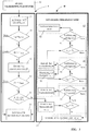
- This first speed range can be determined by a predetermined speed band and / or by a limit speed n limit , such as Fig. 3 in the left column shows.
- a predetermined limit speed n limit for example, with starting gas, it is checked whether the actual speed n is smaller than a predetermined limit speed n limit .
- a minimum speed can be queried. If the predetermined condition is satisfied, then an operation is in the first speed range B, as the FIGS. 4 and 5 play.
- the maximum limit speed n limit can correspond to a starting speed n STR .
- the operation with starting gas is first detected.
- the actual rotational speed n is , as shown in a first decision diamond 30, at least monitored that a predetermined limit speed n limit is not exceeded. Thereafter, it is checked, as shown by the decision diamond 31, whether over a predetermined minimum operating time T min, the actual speed n is smaller than the limit speed n limit . If this condition is fulfilled, a time window ZF is opened in accordance with field 32.
- the time window IF according to field 32 has an upper time limit T max , which is monitored as shown in decision diamond 33. If the time limit T max is reached without a predetermined user action being carried out, the internal combustion engine 3 continues to run in a normal, the first operating state I. This first operating state I is indicated in field 35.
- the internal combustion engine 3 is operated in the first operating state I whenever the result of the checks according to the decisions in the decision bars 30, 31, and 33 is answered "no".
- time window ZF according to decision diamond 33 is open and the user executes a predetermined user action, this is queried in the method sequence, as shown in the decision diamond 34. If a predetermined user action is detected, it is changed from the operating state I to the special operating state II.
- the detected user action expediently leads to an increase in the rotational speed n is of the internal combustion engine 3 into a second rotational speed range C and / or D ( FIGS. 4 . 5 ).
- FIGS. 4 and 5 show the second speed range C and / or D above the first speed range B.
- the user action is given by the fact that the user completely depresses the throttle 6 in the direction of arrow 8, the engine thus by the user in the second speed range C and / or D. operated under full throttle.
- the special mode II is initiated and the full throttle position - preferably by the user - maintained until the engine 3 gives a feedback to the user that the calibration was successful.
- the user must carry out the predetermined user action permanently over a predetermined period of time in order to initiate the owner mode II. Subsequently, the internal combustion engine 3 in conjunction with the control unit 15, the process for adjusting the composition of the mixture 10 of fuel and combustion air automatically perform up to a process end.
- the start of the internal combustion engine 3 may also be a warm start.
- a warm start is a start after the previous run of the internal combustion engine 3.
- the internal combustion engine 3 may have a temperature higher than the ambient temperature. If the user wishes to adapt the composition of a mixture 10 of fuel and combustion air after a warm start, he may perform the warm start in a start position of the mixture formation device 9 to initiate the special operating state.
- the warm start is detected by the control unit 15 and then detected as the first start of the engine 3.
- the internal combustion engine 3 is operated after the start in a first operating state for a predetermined operating time T min in a first speed range B. After the operating time T min has elapsed, the time window is opened ZF to jump to a special operating state II after execution of a predetermined user action, eg. B. Full throttle.
- the method for adjusting the composition of a mixture 10 of fuel and combustion air is advantageously carried out in a plurality of calibration stages 40, 50, 60.
- the adaptation of the composition of the mixture 10 of fuel and combustion air in three calibration stages 40, 50, 60 in particular automated without further compelling user actions.
- the first calibration stage 40 After the first calibration stage 40 has elapsed, it is queried in accordance with decision diamond 41 whether the calibration was successful. If no error is detected, the branching takes place in the method as shown in decision diamond 41. In the branch "Yes”, the second calibration stage 50 is branched. If the calibration was unsuccessful, the system branches to the field 19 via the "no" branch in accordance with the decision diamond 41 and the internal combustion engine 3 is switched off.
- the calibration may be completed upon successful completion of the second calibration stage 50.
- Successful calibration is reported to the user through feedback.
- the speed of the engine 3 may be lowered to a feedback speed n Re , as shown in block 52. It may also be expedient to switch off the internal combustion engine as feedback to the user.
- the third calibration stage 60 can advantageously be released only under predetermined further boundary conditions. Thus, it may be necessary to allow the implementation of the third calibration stage 60 only when a diagnostic device is connected. Suitably, the third calibration stage 60 can be approached only in service in a workshop. In the third calibration stage 60, the mixture is calibrated at idling speed LL . If the third calibration stage 60 has passed successfully, the internal combustion engine 3 is preferably switched off, as shown in box 62.
- the feedback speed n Re is advantageously less than n max, and in particular less than n nom.
- the feedback speed n Re is preferably greater than n or n STR LL, but in particular may be zero and be achieved by stopping the engine. 3
- the user can - he keeps the throttle 6 still pressed - go from the gas and transfer the throttle 6 opposite to the arrow 8 in the neutral position.
- an adaptation of the composition of a mixture 10 of fuel and combustion air at idle in the calibration stage 60 can now take place.
- decision diamond 61 it is then queried whether the calibration of the third calibration stage 60 was successful. If an error occurs, the system branches to the field 19 via the "no" branch and the internal combustion engine 3 is switched off. If the calibration of the third calibration stage 60 was successful, the internal combustion engine 3 is advantageously switched off. The switching off of the internal combustion engine serves as feedback to the user, in which case it is possible in particular to read out via a connected diagnostic device whether the calibration has been successful.
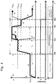
- FIG. 4 An example of the procedure for adjusting the composition of a mixture 10 of fuel and combustion air is in a first advantageous embodiment in Fig. 4 played.
- the internal combustion engine 3 is started with starting gas, whereby the internal combustion engine 3 passes through at a starting rotational speed n STR .
- the starting speed n STR corresponds to a limit speed n limit .
- This start pass must for a fixed operating time BZ the time T min of the embodiment 30 seconds, so that the time window ZF to initiate the special operating state II is opened.
- a so-called full-load calibration is performed in a first calibration stage 40.
- the internal combustion engine is advantageously decelerated at a defined speed.
- the ignition is advantageously clocked out and adjusted the mixture. If the regulation criterion, for example a predefined speed, can not be achieved in the second speed range C of the calibrating stage 40, the calibration stops by lowering the speed in accordance with the falling edge H. In particular, the speed n drops to 'zero'. The engine 3 is turned off.
- the second calibration module 50 successfully completed in the further, second speed range D is advantageously lowered via the control unit 15, the rotational speed n of the engine 3 in a process section E to a feedback speed n Re.
- This significant reduction of the speed is advantageously carried out by the control unit 15, although the user is still full throttle, as the illustrated course of the throttle position over time shows.
- the throttle lever is in accordance with the shift indicator Fig. 4 also in the process section E in position "1", ie in position "full throttle".
- the internal combustion engine 3 is adapted by the calibration to changed boundary conditions, for example adapted to the height of the place of use or the prevailing air pressure or to newly installed spare parts or to a cleaned air filter.
- Fig. 5 shows an alternative process flow of initiating a process for adjusting the composition of a mixture 10 of fuel and combustion air. It takes place - accordingly Fig. 4 in section A, a start of the internal combustion engine 3 under starting gas; the internal combustion engine 3 will run up to start speed n STR .
- the speed range B is maintained for an operating time BZ with a time duration T min of 30 seconds in the exemplary embodiment; after the minimum operating time BZ has elapsed, the time window ZF is opened in accordance with field 32 in FIG Fig. 3 open.
- the user moves the throttle from the position "0" (idle) to the position "1" (full throttle), as the representation of the throttle position over time below the speed curve shows the speed n of the engine 3 is run up to a rated speed n nenn and over a period T N of advantageously 30 seconds carried out a calibration. If the calibration in the second speed range C over the minimum time T N is faulty, the speed falls in accordance with the falling edge H to zero. The internal combustion engine 3 goes out. If the calibration is successful, falls under the action of the control unit 15 - in spite of the throttle lever in position "1" (full throttle) - the speed in the section E to a feedback speed n Re.
- the user recognizes a completed calibration and goes off the gas; the throttle lever assumes the position "0" (idle).
- the internal combustion engine 3 drops to the idling speed n LL .
- an idle calibration according to the calibration stage 60 in FIG Fig. 3 take place after the successful completion of the internal combustion engine 3 is turned off. That the Combustion engine 3 supplied mixture 10 is adapted to the density of the combustion air.
Landscapes
- Engineering & Computer Science (AREA)
- Chemical & Material Sciences (AREA)
- Combustion & Propulsion (AREA)
- Mechanical Engineering (AREA)
- General Engineering & Computer Science (AREA)
- Combined Controls Of Internal Combustion Engines (AREA)
- Electrical Control Of Air Or Fuel Supplied To Internal-Combustion Engine (AREA)
Abstract
Description
- Die Erfindung betrifft ein Verfahren zur Einleitung einer Anpassung der Zusammensetzung eines Gemisches aus Kraftstoff und Verbrennungsluft, wobei das Gemisch einem Brennraum eines gemischgeschmierten Verbrennungsmotors in einem Arbeitsgerät zugeführt ist. Zumindest eine Teilmenge des dem Verbrennungsmotor zugeführten Kraftstoffs ist über ein elektromagnetisch gesteuertes Kraftstoffventil zugeführt, wobei in einem Betriebszustand des Verbrennungsmotors abhängig von Betriebsparametern des Verbrennungsmotors die zugeführte Teilmenge des Kraftstoffs durch Öffnen und Schließen des elektromagnetischen Kraftstoffventils zugemessen wird.
- Die Anpassung des Gemisches aus Kraftstoff und Verbrennungsluft ist im besonderen Maße abhängig vom Luftdruck bzw. von der Höhe des Einsatzortes des Arbeitsgerätes. Es ist bekannt, dass der Benutzer mit entsprechendem Werkzeug an der Gemischbildungseinrichtung des Verbrennungsmotors Einstellungen zur Anpassung der Höhe des Arbeitsortes vornehmen kann, beispielsweise durch manuelles Drehen der Vergaserschraube mit einem Werkzeug wie einem Schraubendreher oder dgl. Dies ist aufwendig und bedingt das Mitführen von Werkzeug. Eine Anpassung des Gemisches aus Kraftstoff und Verbrennungsluft wird zweckmäßig auch dann erfolgen, wenn Bauteile des Arbeitsgerätes gereinigt oder ausgetauscht wurden, wie z. B. ein die Verbrennungsluft reinigender Luftfilter.
- Der Erfindung liegt die Aufgabe zugrunde, ein Verfahren zur Anpassung der Zusammensetzung eines Gemisches aus Kraftstoff und Verbrennungsluft anzugeben, das vom Benutzer ohne besonderes Werkzeug einfach eingeleitet werden kann.
- Die Aufgabe wird erfindungsgemäß nach den Merkmalen des Anspruchs 1 gelöst.
- Zunächst ist vorgesehen, dass die Anpassung der Zusammensetzung des Gemisches in einem von dem Betriebszustand des Verbrennungsmotors abweichenden Sonderbetriebszustand ausgeführt wird. Um diesen Sonderbetriebszustand des Verbrennungsmotors einzuleiten, muss der Benutzer den Verbrennungsmotor zunächst starten und nach dem Start eine vorgegebene Betriebszeit in einem ersten Drehzahlbereich betreiben. Ist die vorgegebene Betriebszeit abgelaufen und während der ersten Betriebszeit der erste Drehzahlbereich eingehalten, kann der Benutzer zur Anpassung der Zusammensetzung des Gemisches den Sonderbetriebszustand durch eine einfache Benutzerhandlung einleiten. Als Benutzerhandlung kann ein einfaches oder Mehrfaches Drücken des Gashebels und/oder des Sperrhebels zweckmäßig sein.
- Der Benutzer nimmt während der ersten Betriebszeit des Verbrennungsmotors vorteilhaft keine weiteren Handlungen vor und belässt den Verbrennungsmotor in seinem Betriebszustand.
- Eine Benutzerhandlung zur Einleitung des Sonderbetriebszustandes besteht zweckmäßig darin, dass durch die Benutzerhandlung eine Erhöhung der Drehzahl des Verbrennungsmotors in einen zweiten Drehzahlbereich bewirkt wird. Der zweite Drehzahlbereich liegt vorteilhaft oberhalb des ersten Drehzahlbereichs und wird in einfacher Weise dadurch erreicht, dass der Benutzer den Verbrennungsmotor im zweiten Drehzahlbereich unter Vollgas betreibt. Der Benutzer kann somit den Sonderbetriebszustand nach Ablauf der vorgegebenen Betriebszeit dadurch einleiten, dass er den Gashebel des Arbeitsgerätes niederdrückt, insbesondere vollständig niederdrückt, also Vollgas gibt.
- Dabei wird der Verbrennungsmotor in dem ersten und/oder zweiten Drehzahlbereich insbesondere lastfrei betrieben.
- Der Start des Verbrennungsmotors ist insbesondere ein Kaltstart, so dass der Verbrennungsmotor während der vorgegebenen Betriebszeit nach dem Kaltstart mit Startgas in dem ersten Drehzahlbereich betrieben wird. In diesem ersten Drehzahlbereich läuft die Maschine warm und konditioniert sich.
- Um die Benutzerhandlung einzuleiten, öffnet nach Ablauf der vorgegebenen Betriebszeit zweckmäßig ein Zeitfenster. Dieses Zeitfenster erstreckt sich nach Ablauf der vorgegebenen Betriebszeit über eine Zeitspanne von vorteilhaft 15 Sekunden bis 360 Sekunden, insbesondere über eine Zeitspanne von 30 Sekunden bis 90 Sekunden, besonders vorteilhaft von 30 Sekunden bis 60 Sekunden. Erfolgt innerhalb des Zeitfensters keine vorgegebene Benutzerhandlung, wird der Verbrennungsmotor im normalen Betriebszustand betrieben.
- Die Kalibrierung oder Anpassung der Zusammensetzung des Gemisches erfolgt insbesondere in mehreren aufeinander folgenden Kalibrierstufen. Dabei kann in einer ersten Kalibrierstufe die Anpassung des Gemisches bei Nenndrehzahl des Verbrennungsmotors erfolgen. Die erste Kalibrierstufe dient vorteilhaft der Einstellung der maximalen Leistung des Arbeitsgerätes.
- In einer vorteilhaft folgenden zweiten Kalibrierstufe erfolgt die Anpassung des Gemisches bei Höchstdrehzahl des Verbrennungsmotors.
- In Weiterbildung der Erfindung ist vorgesehen, eine dritte Kalibrierstufe freizuschalten, wenn die erste und die zweite Kalibrierstufe erfolgreich abgeschlossen wurden. In einer derartigen dritten Kalibrierstufe kann die Anpassung des Gemisches für den Leerlauf erfolgen. Vorteilhaft kann die dritte Kalibrierstufe nur unter vorgegebenen weiteren Randbedingungen durchgeführt werden, beispielsweise nur mit Anschluss eines Diagnosegerätes.
- Während der Anpassung des Gemisches in den unterschiedlichen Kalibrierstufen ist vorgesehen, bei erfolglosem Abschluss einer Kalibrierstufe den Sonderbetriebszustand zu beenden und in den Verbrennungsmotor abzuschalten. Dies dient dem Benutzer beispielsweise als Rückmeldung, dass die Kalibrierung der Maschine nicht erfolgreich war.
- Bei erfolgreichem Abschluss der Kalibrierstufe erhält der Benutzer eine entsprechende Rückmeldung, so z. B. eine Absenkung der Drehzahl n des Verbrennungsmotors auf eine Drehzahl, die vorteilhaft unterhalb des zweiten Drehzahlbereichs liegt. Die Drehzahl nRück liegt vorteilhaft oberhalb des ersten Drehzahlbereichs und unterhalb des zweiten Drehzahlbereichs. Es kann zweckmäßig sein, bei erfolgreichem Abschluss z. B. der dritten Kalibrierstufe den Verbrennungsmotor über die Steuerungseinheit abzuschalten.
- Die zugeführte Teilmenge des Kraftstoffes wird insbesondere durch getaktetes Öffnen des elektromagnetischen Kraftstoffventils von einer Steuereinheit zugemessen. Vorteilhaft wird die gesamte Menge des der Verbrennungsluft zugeführten Kraftstoffs über das elektromagnetische Kraftstoffventil zugemessen.
- Das Gemisch im Brennraum wird durch den Zündfunken einer Zündkerze gezündet, welche von einer Steuereinheit angesteuert ist. Um die Nenndrehzahl des Verbrennungsmotors einzustellen, ist vorteilhaft vorgesehen, durch Unterdrückung des Zündfunkens die Drehzahl einzustellen. Dieses wird auch als "Austakten" bezeichnet.
- Weitere Merkmale der Erfindung ergeben sich aus den weiteren Ansprüchen, der Beschreibung und der Zeichnung, in der nachfolgend im Einzelnen beschriebene Ausführungsbeispiele der Erfindung dargestellt sind. Es zeigen:
- Fig. 1
- in einer schematischen Schnittdarstellung ein erstes Arbeitsgerät mit einem Verbrennungsmotor,
- Fig. 2
- eine Seitenansicht auf ein weiteres Arbeitsgerät mit einem Verbrennungsmotor,
- Fig. 3
- ein Ablaufdiagramm zur Anpassung der Zusammensetzung eines Gemisches aus Kraftstoff und Verbrennungsluft für einen Verbrennungsmotor,
- Fig. 4
- eine schematische Wiedergabe eines Verfahrensablaufs mehrerer aufeinander folgender Kalibrierstufen,
- Fig. 5
- eine schematische Darstellung eines Verfahrensablaufs aufeinander folgender Kalibrierstufen mit einer Kalibrierstufe zur Anpassung des Gemisches bei Leerlaufdrehzahl.
- Das in
Fig. 1 dargestellte Arbeitsgerät 1 ist eine Motorkettensäge 2 mit einem Verbrennungsmotor 3, der als Werkzeug 5 eine auf einer Führungsschiene 4 umlaufende Sägekette antreibt. Der Verbrennungsmotor 3 wird in seiner Drehzahl von einem Benutzer durch einen Gashebel 6 gesteuert, dem eine Gashebelsperre 7 zugeordnet ist. Der Gashebel 6 kann vorteilhaft zur Erhöhung der Drehzahl des Verbrennungsmotors 3 erst dann in Pfeilrichtung 8 in Richtung Vollgas niedergedrückt werden, wenn die Gashebelsperre 7 betätigt ist. Der Gashebel 6 und die Gashebelsperre 7 sind in einem hinteren Handgriff 19 des Arbeitsgerätes 1 vorgesehen. - Im gezeigten Ausführungsbeispiel ist der Verbrennungsmotor 3 ein vorzugsweise gemischgeschmierter Verbrennungsmotor, insbesondere ein Zeitaktmotor, ein gemischgeschmierter Viertaktmotor oder dgl. Der Verbrennungsmotor 3 ist insbesondere ein einzylindriger Verbrennungsmotor.
- Zum Betrieb des Verbrennungsmotors 3 wird über eine Gemischbildungseinrichtung 9 ein Gemisch 10 aus Kraftstoff und Verbrennungsluft zugeführt. Das Gemisch 10 füllt einen Brennraum 11 des Verbrennungsmotors 3 und wird von einer Zündkerze 12 durch Abgeben eines Zündfunkens gezündet.
- Der über die Gemischbildungseinrichtung 9 der zuströmenden Verbrennungsluft zugeführte Kraftstoff wird zumindest in einer Teilmenge über ein elektromagnetisches Kraftstoffventil 13 zugemessen. In einem Betriebszustand I des Verbrennungsmotors 3, der auch als normaler Betriebszustand bezeichnet werden kann, wird die Zusammensetzung des Gemisches 10 abhängig von Betriebsparametern durch Steuerung des elektromagnetischen Kraftstoffventils 13 geändert. Hierzu kann eine Steuereinheit 15 vorgesehen sein, welcher z. B. über einen Drehzahlsensor 16 die Drehzahl des Verbrennungsmotors 3 als ein erster Betriebsparameter zugeführt ist. Über einen weiteren Sensor 17 kann der Steuereinheit 15 der Druck im Kurbelgehäuse 18 und/oder die Temperatur im Kurbelgehäuse 18 als weitere Betriebsparameter gemeldet werden. Die Aufzählung der Betriebsparameter ist beispielhaft; es können mehr oder weniger Betriebsparameter in der Steuereinheit 15 verarbeitet werden.
- Die Steuereinheit 15 ist über eine Steuerleitung 14 mit dem Kraftstoffventil 13 verbunden. Die Steuereinheit 15 steuert die Öffnungszeit des Kraftstoffventils 13. Die Öffnungszeit des Kraftstoffventils 13 bestimmt die zugeführte Teilmenge des dem Verbrennungsmotors zugeführten Kraftstoffs.
- Das Kraftstoffventil 13 ist zweckmäßig ein getaktetes Kraftstoffventil, d. h., das Kraftstoffventil 13 wird durch Anlegen einer Taktfrequenz geöffnet und geschlossen; durch Änderung der Taktfrequenz kann die Gesamtöffnungsdauer des Kraftstoffventils 13 eingestellt und somit die der Gemischbildungseinrichtung zufließende Kraftstoffmenge, insbesondere eine Teilmenge an Kraftstoff zugemessen werden.
- Das Kraftstoffventil 13 ist vorteilhaft ein elektromagnetisches Kraftstoffventil welches stromlos geöffnet ist. Auch ein stromlos geschlossenes elektromagnetisches Kraftstoffventil kann vorteilhaft sein.
- Die Förderung des Kraftstoffs in die Gemischbildungseinrichtung 9 erfolgt insbesondere über den im Ansaugkanal der Gemischbildungseinrichtung 9 anstehenden Unterdruck; ist das Kraftstoffventil 13 geöffnet, wird Kraftstoff angesaugt.
- Das in
Fig. 2 dargestellte Ausführungsbeispiel eines Arbeitsgerätes ist ein Trennschleifer 20, in dessen Gehäuse ein Verbrennungsmotor entsprechendFig. 1 angeordnet ist. Auch dieser Verbrennungsmotor ist in seiner Drehzahl über den Gashebel 6 steuerbar, wobei der Gashebel 6 vorteilhaft erst nach Betätigung der Gashebelsperre 7 in Pfeilrichtung 8 in Richtung Vollgas verschwenkt werden kann. Der Gashebel 6 und die Gashebelsperre 7 sind in einem hinteren Handgriff 19 des Arbeitsgerätes 1 vorgesehen. - Bei derartigen Verbrennungsmotoren3 ändert sich das Gemisch 10 aus Kraftstoff und Verbrennungsluft in Abhängigkeit vom Luftdruck bzw. in Abhängigkeit von der Höhe des Einsatzortes des Arbeitsgerätes 1. Verändert sich die Dichte der Verbrennungsluft, würde bei gleicher Zumessung der Kraftstoffmenge das Gemisch 10 zu fett; daher ist es zweckmäßig, die Gemischbildungseinrichtung 9 vor Inbetriebnahme des Arbeitsgerätes 1 derart zu kalibrieren, dass eine Anpassung der Zusammensetzung des Gemisches 10 aus Kraftstoff und Verbrennungsluft an den Luftdruck bzw. an die Höhe des Einsatzortes des Arbeitsgerätes 1 erzielt ist.
- Nach dem erfindungsgemäßen Verfahren gemäß dem Ablaufdiagramm in
Fig. 3 wird zur Einleitung der Anpassung der Zusammensetzung des Gemisches 10 aus Kraftstoff und Verbrennungsluft der Verbrennungsmotor 3 aus einem ersten Betriebszustand I in einen zweiten Betriebszustand versetzt, der einem Sonderbetriebszustand II entspricht. Im Sonderbetriebszustand II wird die Gemischbildungseinrichtung 9 kalibriert und die Zusammensetzung des Gemisches 10 aus Kraftstoff und Verbrennungsluft angepasst. - Der erste Betriebszustand I kann auch als normaler Betriebszustand des Verbrennungsmotors bezeichnet werden, in dem das Arbeitsgerät bestimmungsgemäß genutzt wird.
- Die Einleitung der Anpassung der Zusammensetzung des Gemisches 10 aus Kraftstoff und Verbrennungsluft erfolgt in Abhängigkeit zumindest einer vorgegebenen Benutzerhandlung insbesondere mittels der zum Bedienen des Arbeitsgerätes 1 vorgesehenen Bedienelemente wie z. B. dem Gashebel 6 und/oder der Gashebelsperre 7. Um von dem ersten Betriebszustand I des Verbrennungsmotors 3 in einen zur Anpassung der Zusammensetzung des Gemisches 10 notwendigen Sonderbetriebszustand II zu gelangen, muss der Verbrennungsmotor 3 vom Benutzer zunächst gestartet werden. Dabei ist der Start des Verbrennungsmotors 3 zweckmäßig ein Kaltstart. Zum Kaltstart kann an der Gemischbildungseinrichtung 9 eine entsprechende Kaltstartklappe oder dgl. betätigt sein. Als Kaltstart wird ein erster Start des Verbrennungsmotors verstanden, bei dem der Verbrennungsmotor 3 beim Start höchstens Umgebungstemperatur hat. Hat der Verbrennungsmotor 3 Umgebungstemperatur, kann davon ausgegangen werden, dass eine erste Inbetriebnahme des Verbrennungsmotors 3 vorliegt. Dies entspricht einem Kaltstart.
- Nach dem Start des Verbrennungsmotors 3 ersichtlich in Feld 36 in
Fig. 3 muss dieser für eine vorgegebene Betriebszeit BZ der Zeitdauer Tmin in einem ersten Drehzahlbereich betrieben werden. Dieser erste Drehzahlbereich kann durch ein vorgegebenes Drehzahlband und/oder durch eine Grenzdrehzahl ngrenz bestimmt sein, wieFig. 3 in der linken Spalte zeigt. Während dieser Betriebszeit BZ, beispielsweise mit Startgas, wird überprüft, ob die Ist-Drehzahl nist kleiner einer vorgegebenen Grenzdrehzahl ngrenz ist. Bei Vorgabe eines Drehzahlbandes kann auch dessen untere Grenze, z. B. eine Minimaldrehzahl abgefragt werden. Ist die vorgegebene Bedingung erfüllt, so liegt ein Betrieb im ersten Drehzahlbereich B vor, wie dieFiguren 4 und5 wiedergeben. Die maximale Grenzdrehzahl ngrenz kann einer Startdrehzahl nSTR entsprechen. - Entsprechend dem Ablaufdiagramm in
Fig. 3 wird im Feld 37 zunächst der Betrieb mit Startgas festgestellt. Die Ist-Drehzahl nist wird, wie in einer ersten Entscheidungsraute 30 dargestellt, zumindest darauf überwacht, dass eine vorgegebene Grenzdrehzahl ngrenz nicht überschritten wird. Danach wird überprüft, wie durch die Entscheidungsraute 31 dargestellt, ob über eine vorgegebene minimale Betriebszeit Tmin die Ist-Drehzahl nist kleiner als die Grenzdrehzahl ngrenz ist. Ist diese Bedingung erfüllt, wird gemäß Feld 32 ein Zeitfenster ZF geöffnet. Das Zeitfenster ZF gemäß Feld 32 hat eine obere Zeitgrenze Tmax, die, wie in der Entscheidungsraute 33 dargestellt, überwacht wird. Wird die Zeitgrenze Tmax erreicht, ohne dass eine vorgegebene Benutzerhandlung ausgeführt wird, läuft der Verbrennungsmotor 3 in einem normalen, dem ersten Betriebszustand I weiter. Dieser erste Betriebszustand I ist im Feld 35 angegeben. Der Verbrennungsmotor 3 wird immer dann in dem ersten Betriebszustand I betrieben, wenn das Ergebnis der Überprüfungen gemäß der Entscheidungen in den Entscheidungsrauten 30, 31, und 33 mit "Nein" beantwortet ist. - Ist das Zeitfenster ZF gemäß Entscheidungsraute 33 offen und führt der Benutzer eine vorgegebene Benutzerhandlung aus, wird dies im Verfahrensablauf abgefragt, wie in der Entscheidungsraute 34 dargestellt ist. Wird eine vorgegebene Benutzerhandlung festgestellt, wird von dem Betriebszustand I in den Sonderbetriebszustand II gewechselt.
- Die festgestellte Benutzerhandlung, siehe
Figur 3 , dort Feld 34, führt zweckmäßig zu einer Erhöhung der Drehzahl nist des Verbrennungsmotors 3 bis in einen zweiten Drehzahlbereich C und/oder D (Figuren 4 ,5 ). Wie dieFiguren 4 und5 zeigen, liegt der zweite Drehzahlbereich C und/oder D oberhalb des ersten Drehzahlbereichs B. Insbesondere ist die Benutzerhandlung dadurch gegeben, dass der Benutzer den Gashebel 6 in Pfeilrichtung 8 vollständig niederdrückt, der Verbrennungsmotor somit durch den Benutzer im zweiten Drehzahlbereich C und/oder D unter Vollgas betrieben wird. Mit der Stellung "Vollgas" des Gashebels 6 wird der Sonderbetriebszustand II eingeleitet und die Vollgasstellung - vorzugsweise durch den Benutzer - beibehalten, bis der Verbrennungsmotor 3 eine Rückmeldung an den Benutzer gibt, dass die Kalibrierung erfolgreich war. - Der Benutzer hält mit der Einleitung des Sonderbetriebszustandes II den Gashebel 6 dauerhaft betätigt, vorteilhaft bis zu einem Endanschlag gedrückt, was einer Vollgasstellung entspricht. Es kann vorteilhaft sein, dass mit der Einleitung des Sonderbetriebszustandes II durch eine vorgegebene Benutzerhandlung die Steuereinheit 15 die Steuerung des Verbrennungsmotors 3 übernimmt und das Verfahren zur Anpassung der Zusammensetzung des Gemisches 10 aus Kraftstoff und Verbrennungsluft selbsttätig bis zu einem Verfahrensende durchführt.
- Es kann auch vorgesehen sein, dass der Benutzer die vorgegebene Benutzerhandlung über einen vorgegebenen Zeitraum dauerhaft durchführen muss, um den Sönderbetriebszustand II einzuleiten. Anschließend kann der Verbrennungsmotor 3 in Verbindung mit der Steuereinheit 15 das Verfahren zur Anpassung der Zusammensetzung des Gemisches 10 aus Kraftstoff und Verbrennungsluft selbsttätig bis zu einem Verfahrensende durchführen.
- Im Rahmen der Erfindung kann der Start des Verbrennungsmotors 3 auch ein Warmstart sein. Als Warmstart wird ein Start nach vorherigem Lauf des Verbrennungsmotors 3 bezeichnet. Der Verbrennungsmotor 3 kann eine Temperatur aufweisen, die höher als die Umgebungstemperatur ist. Möchte der Benutzer eine Anpassung der Zusammensetzung eines Gemisches 10 aus Kraftstoff und Verbrennungsluft nach einem Warmstart, so kann er zur Einleitung des Sonderbetriebszustandes den Warmstart in einer Startposition der Gemischbildungseinrichtung 9 durchführen. Der Warmstart wird von der Steuereinheit 15 erkennt und dann als erster Start des Verbrennungsmotors 3 detektiert. Sofern der Benutzer während der ersten Betriebszeit keine weiteren Benutzerhandlungen vornimmt wird der Verbrennungsmotor 3 nach dem Start in einem ersten Betriebszustand eine vorgegebene Betriebszeit Tmin in einem ersten Drehzahlbereich B betrieben. Nach Ablauf der Betriebszeit Tmin erfolgt die Öffnung des Zeitfensters ZF zum Sprung in einen Sonderbetriebszustand II nach Ausführung einer vorgegebenen Benutzerhandlung, z. B. Vollgas geben.
- Die Anpassung der Zusammensetzung des Gemisches 10 aus Kraftstoff und Verbrennungsluft erfolgt insbesondere lastfrei, d. h., ohne Last am Werkzeug 5. So ist bei dem Ausführungsbeispiel gemäß
Figur 1 als Werkzeug 5 eine Sägekette auf der Führungsschiene montiert, allerdings wird das Verfahren zur Anpassung des Gemisches nur dann durchgeführt, wenn die Sägekette nicht zum Schnitt im Holz eingesetzt wird. Die Sägekette kann lastfrei mitlaufen. Entsprechendes gilt z. B. für ein Arbeitsgerät nachFig. 2 . - Das Verfahren zur Anpassung der Zusammensetzung eines Gemisches 10 aus Kraftstoff und Verbrennungsluft erfolgt vorteilhaft in mehreren Kalibrierstufen 40, 50, 60. Nach dem Ausführungsbeispiel erfolgt nach Einleitung des Sonderbetriebszustands II (
Fig. 3 ) die Anpassung der Zusammensetzung des Gemisches 10 aus Kraftstoff und Verbrennungsluft in drei Kalibrierstufen 40, 50, 60, insbesondere automatisiert ohne weitere zwingende Benutzerhandlungen. - Aufgrund der im Ausführungsbeispiel vorgegebenen Benutzerhandlung "Vollgas" läuft der Verbrennungsmotor 3 zunächst bei einer Nenndrehzahl nnenn. Dieser Betrieb bei Nenndrehzahl nnenn muss für eine Minimalzeit TN vorliegen. Während dieser Minimalzeit TN erfolgt die Kalibrierung in der ersten Kalibrierstufe 40 bei Nenndrehzahl nnenn. Diese Nenndrehzahl nnenn wird - auch unter Vollgas - durch Austakten der Zündung erzielt. Das Gemisch 10 im Brennraum 11 wird durch den Zündfunken der Zündkerze 12 gezündet, die von einer Zündvorrichtung, im Ausführungsbeispiel die Steuereinheit 15, angesteuert wird. Die Nenndrehzahl nnenn wird durch Unterdrückung des Zündfunkens durch die Steuereinheit 15 eingeregelt. Der Verbrennungsmotor 3 wird auf die Nenndrehzahl nnenn abgeregelt.
- Nach Ablauf der ersten Kalibrierstufe 40 wird gemäß der Entscheidungsraute 41 abgefragt, ob die Kalibrierung erfolgreich war. Wird kein Fehler festgestellt, erfolgt im Verfahren die Verzweigung wie in der Entscheidungsraute 41 dargestellt. Im Zweig "Ja" wird auf die zweite Kalibrierstufe 50 verzweigt. War die Kalibrierung nicht erfolgreich, wird über den "Nein"-Zweig gemäß der Entscheidungsraute 41 auf das Feld 19 verzweigt und der Verbrennungsmotors 3 abgeschaltet.
- Wurde die erste Kalibrierstufe 40 erfolgreich abgeschlossen, erfolgt die Erhöhung der Drehzahl nist des Verbrennungsmotors 3 auf eine Maximaldrehzahl nmax. Vorteilhaft liegt dieser Drehzahlbereich der Maximaldrehzahl nmax für eine Minimalzeit TH vor. Während dieser Minimalzeit TH erfolgt die Kalibrierung in der zweiten Kalibrierstufe 50 zwecks weiterer Anpassung des Gemisches 10 aus Kraftstoff und Verbrennungsluft. Wie in der Entscheidungsraute 51 dargestellt, wird dann im Verfahren abgefragt, ob die Kalibrierung der zweiten Kalibrierstufe 50 erfolgreich war. In einem Fehlerfall in der zweiten Kalibrierstufe 50 verzweigt die Entscheidungsraute 51 auf den "Nein"-Zweig, der zum Feld 19 und zum Abschalten des Verbrennungsmotors 3 führt.
- Alternativ kann die Kalibrierung nach erfolgreichem Abschluss der zweiten Kalibrierstufe 50 abgeschlossen sein. Die erfolgreiche Kalibrierung wird durch eine Rückmeldung an den Benutzer gemeldet. Als Rückmeldung einer erfolgreichen Kalibrierung kann die Drehzahl des Verbrennungsmotors 3 auf eine Rückmeldedrehzahl nRück abgesenkt werden, wie Feld 52 zeigt. Es kann auch zweckmäßig sein, als Rückmeldung an den Benutzer den Verbrennungsmotor auszuschalten.
- War die Kalibrierung auch in der zweiten Kalibrierstufe 50 erfolgreich, kann die dritte Kalibrierstufe 60 vorteilhaft nur unter vorgegebenen weiteren Randbedingungen freigeschaltet werden. So kann es erforderlich sein, die Durchführung der dritten Kalibrierstufe 60 nur bei Anschluss eines Diagnosegerätes zuzulassen. Zweckmäßig kann die dritte Kalibrierstufe 60 nur im Service in einer Werkstatt angefahren werden. In der dritten Kalibrierstufe 60 erfolgt eine Kalibrierung des Gemisches bei Leerlaufdrehzahl nLL. Wurde die dritte Kalibrierstufe 60 erfolgreich durchlaufen, wird der Verbrennungsmotor 3 vorzugsweise abgeschaltet, wie Feld 62 darstellt.
- Um vor Ort dem Benutzer die erfolgreiche Kalibrierung des Verbrennungsmotors 3 nach erfolgreichem Durchlaufen der Kalibrierstufen 40 und 50 zurückzumelden, erfolgt nach Abschluss der zweiten Kalibrierstufe 50 vorteilhaft die Absenkung der Drehzahl n des Verbrennungsmotors 3 auf eine Rückmeldedrehzahl nRück. Die Rückmeldedrehzahl nRück ist vorteilhaft kleiner als nmax, insbesondere kleiner als nnenn. Die RückmeldeDrehzahl nRück ist vorzugsweise größer als nSTR bzw. nLL, kann insbesondere aber Null sein und durch Abschalten des Verbrennungsmotors 3 erzielt sein.
- Nach der Rückmeldung kann der Benutzer - hält er den Gashebel 6 noch immer gedrückt - vom Gas gehen und den Gashebel 6 entgegen Pfeilrichtung 8 in Leerlaufstellung überführen. Alternativ kann nun eine Anpassung der Zusammensetzung eines Gemisches 10 aus Kraftstoff und Verbrennungsluft im Leerlauf in der Kalibrierstufe 60 erfolgen. Wie in der Entscheidungsraute 61 dargestellt, wird dann abgefragt, ob die Kalibrierung der dritten Kalibrierstufe 60 erfolgreich war. Trat ein Fehler auf, wird über den "Nein"-Zweig in das Feld 19 verzweigt und der Verbrennungsmotor 3 ausgeschaltet. War die Kalibrierung der dritten Kalibrierstufe 60 erfolgreich, wird vorteilhaft der Verbrennungsmotor 3 ausgeschaltet. Das Ausschalten des Verbrennungsmotors dient als Rückmeldung an den Benutzer, wobei insbesondere über ein angeschlossenes Diagnosegerät ausgelesen werden kann, ob die Kalibrierung erfolgreich war.
- Ein Beispiel des Verfahrensablaufs zur Anpassung der Zusammensetzung eines Gemisches 10 aus Kraftstoff und Verbrennungsluft ist in einer ersten vorteilhaften Ausführungsform in
Fig. 4 wiedergegeben. Im Abschnitt A erfolgt ein Starten des Verbrennungsmotors 3 mit Startgas, wodurch der Verbrennungsmotor 3 mit einer Startdrehzahl nSTR durchläuft. Die Startdrehzahl nSTR entspricht einer Grenzdrehzahl ngrenz. Dieser Startdurchlauf muss für eine feste Betriebszeit BZ der Zeitdauer Tmin von im Ausführungsbeispiel 30 Sekunden vorliegen, damit das Zeitfenster ZF zum Einleiten des Sonderbetriebszustands II geöffnet wird. - Betätigt der Benutzer innerhalb dieses in
Fig. 3 angegebenen Zeitfensters ZF den Gashebel 6, gibt er insbesondere Vollgas, so erhöht sich die Drehzahl n auf die Drehzahl nnenn. In diesem zweiten Drehzahlbereich C mit erhöhter Drehzahl n erfolgt in einer ersten Kalibrierstufe 40 eine sogenannte Volllastkalibrierung. In der Volllastkalibrierung wird vorteilhaft bei einer definierten Drehzahl der Verbrennungsmotor abgeregelt. Beim Abregeln wird vorteilhaft die Zündung ausgetaktet und das Gemisch angepasst. Kann das Einregelkriterium, beispielsweise eine vorgegebene Drehzahl, im zweiten Drehzahlbereich C der Kälibrierstufe 40 nicht erreicht werden, bricht die Kalibrierung durch Absenkung der Drehzahl gemäß abfallender Flanke H ab. Insbesondere fällt die Drehzahl n auf 'Null' ab. Der Verbrennungsmotor 3 wird ausgeschaltet. - War die Kalibrierung im zweiten Drehzahlbereich C erfolgreich, wird die Austaktung der Zündung unterbunden, so dass - da der Benutzer vorteilhaft unverändert Vollgas gibt - der Verbrennungsmotor 3 auf eine Maximaldrehzahl nmax hochläuft. Während dieses weiteren zweiten Drehzahlbereichs D mit erhöhter Drehzahl erfolgt die Kalibrierung des Gemisches im Hochdrehzahlbereich in der zweiten Kalibrierstufe 50.
- Ist die zweite Kalibrierstufe 50 im weiteren, zweiten Drehzahlbereich D erfolgreich abgeschlossen, wird vorteilhaft über die Steuereinheit 15 die Drehzahl n des Verbrennungsmotors 3 in einem Verfahrensabschnitt E auf eine Rückmeldedrehzahl nRück abgesenkt. Diese signifikante Absenkung der Drehzahl erfolgt vorteilhaft durch die Steuereinheit 15, obwohl vom Benutzer weiterhin Vollgas gegeben wird, wie der dargestellte Verlauf der Gashebelstellung über der Zeit zeigt. Der Gashebel steht gemäß Schaltanzeige in
Fig. 4 auch im Verfahrensabschnitt E in Stellung "1 ", also in Stellung "Vollgas". - Mit Erkennung der Rückmeldedrehzahl nRück geht der Benutzer im Abschnitt F vom Gas; der Gashebel 6 geht in die Leerlaufstellung und der Verbrennungsmotor 3 läuft mit der Leerlaufdrehzahl nLL. Der Verbrennungsmotor 3 wird durch die Kalibrierung an geänderte Randbedingungen angepasst, beispielsweise an die Höhe des Einsatzortes bzw. den herrschenden Luftdruck angepasst oder an neu verbaute Ersatzteile oder an einen gereinigten Luftfilter.
- Es steht dem Benutzer offen, im Abschnitt G durch fortdauerndes Vollgas geben die Drehzahl auf einer Maximaldrehzahl nmax zu halten.
-
Fig. 5 zeigt einen alternativen Verfahrensablauf des Einleitens eines Verfahrens zur Anpassung der Zusammensetzung eines Gemisches 10 aus Kraftstoff und Verbrennungsluft. Es erfolgt - entsprechendFig. 4 - im Abschnitt A ein Start des Verbrennungsmotors 3 unter Startgas; der Verbrennungsmotor 3 wird auf Startdrehzahl nSTR hochlaufen. Der Drehzahlbereich B wird für eine Betriebszeit BZ mit einer Zeitdauer Tmin von im Ausführungsbeispiel angegebenen 30 Sekunden gehalten; nach Ablauf der minimalen Betriebszeit BZ wird das Zeitfenster ZF gemäß Feld 32 inFig. 3 geöffnet. Der Benutzer verlagert den Gashebel aus der Stellung "0" (Leerlauf) in die Stellung "1" (Vollgas), wie die Darstellung der Gashebelstellung über der Zeit unterhalb des Drehzahlverlaufs zeigt Die Drehzahl n des Verbrennungsmotors 3 wird auf eine Nenndrehzahl nnenn hochlaufen und über einen Zeitraum TN von vorteilhaft 30 Sekunden eine Kalibrierung durchgeführt. Ist die Kalibrierung im zweiten Drehzahlbereich C über der Minimalzeit TN fehlerhaft, fällt die Drehzahl gemäß der abfallenden Flanke H auf Null. Der Verbrennungsmotor 3 geht aus. Ist die Kalibrierung erfolgreich, fällt unter Wirkung der Steuereinheit 15 - trotz Stellung des Gashebels in "1" (Vollgas) - die Drehzahl im Abschnitt E auf eine Rückmeldedrehzahl nRück. Der Benutzer erkennt eine abgeschlossene Kalibrierung und geht vom Gas; der Gashebel nimmt die Stellung "0" (Leerlauf) ein. Der Verbrennungsmotor 3 fällt auf die Leerlaufdrehzahl nLL ab. Im Drehzahlbereich F kann nun eine Leerlaufkalibrierung gemäß der Kalibrierstufe 60 inFig. 3 erfolgen, nach deren erfolgreichem Abschluss der Verbrennungsmotor 3 ausgeschaltet wird. Das dem Verbrennungsmotor 3 zugeführte Gemisch 10 ist der Dichte der Verbrennungsluft angepasst.
Claims (19)
- Verfahren zur Anpassung der Zusammensetzung eines Gemisches (10) aus Kraftstoff und Verbrennungsluft, das einem Brennraum (11) eines gerischgeschmierten Verbrennungsmotors (3) in einem Arbeitsgerät (1) zugeführt ist, welches von einem Benutzer geführt ist,- wobei zumindest eine Teilmenge des Kraftstoffs dem Verbrennungsmotor (3) über ein elektromagnetisch gesteuertes Kraftstoffventil (13) zugeführt wird,- und in einem Betriebszustand (I) des Verbrennungsmotors (3) abhängig von Betriebsparametern die zugeführte Teilmenge des Kraftstoffs durch das elektromagnetische Kraftstoffventil (13) zugemessen wird,dadurch gekennzeichnet,- dass die Anpassung der Zusammensetzung des Gemisches (10) in einem von dem Betriebszustand (I) des Verbrennungsmotors (3) abweichenden Sonderbetriebszustand (II) durchgeführt wird,- dass zur Einleitung des Sonderbetriebszustandes (II) der Verbrennungsmotors (3) vom Benutzer zunächst gestartet wird,- dass der Verbrennungsmotor (3) nach dem Start eine vorgegebene Betriebszeit (Tmin) in einem ersten Drehzahlbereich (B) betrieben wird,- und dass nach Ablauf der vorgegebenen Betriebszeit (Tmin) der Sonderbetriebszustand (II) zur Anpassung der Zusammensetzung des Gemisches (10) durch eine Benutzerhandlung eingeleitet wird.
- Verfahren nach Anspruch 1,
dadurch gekennzeichnet, dass die Benutzerhandlung eine Erhöhung der Drehzahl des Verbrennungsmotors (3) in einen zweiten Drehzahlbereich (C, D) bewirkt. - Verfahren nach Anspruch 2,
dadurch gekennzeichnet, dass der zweite Drehzahlbereich (C, D) oberhalb des ersten Drehzahlbereichs (B) liegt. - Verfahren nach Anspruch 2,
dadurch gekennzeichnet, dass der Verbrennungsmotor (3) durch den Benutzer im zweiten Drehzahlbereich (C, D) unter Vollgas betrieben wird. - Verfahren nach einem der Ansprüche 1 bis 4,
dadurch gekennzeichnet, dass der Verbrennungsmotor (3) in einem Drehzahlbereich (B, C, D) lastfrei betrieben wird. - Verfahren nach einem der Ansprüche 1 bis 5,
dadurch gekennzeichnet, dass der Start des Verbrennungsmotors (3) ein Kaltstart ist. - Verfahren nach Anspruch 6,
dadurch gekennzeichnet, dass der Verbrennungsmotor (3) während der vorgegebenen Betriebszeit (Tmin) nach dem Kaltstart mit Startgas im ersten Drehzahlbereich (B) betrieben wird. - Verfahren nach Anspruch 1,
dadurch gekennzeichnet, dass nach Ablauf der vorgegebenen Betriebszeit (Tmin) ein Zeitfenster (ZF) öffnet. - Verfahren nach Anspruch 8,
dadurch gekennzeichnet, dass sich das Zeitfenster (ZF) nach Ablauf der vorgegebenen Betriebszeit (Tmin) über eine Zeitspanne von 15 bis 360 Sekunden erstreckt. - Verfahren nach Anspruch 8 oder 9,
dadurch gekennzeichnet, dass außerhalb des Zeitfensters (ZF) der Verbrennungsmotor (3) im normalen Betriebszustand (I) betrieben wird. - Verfahren nach einem der Ansprüche 1 bis 10,
dadurch gekennzeichnet, dass die Anpassung der Zusammensetzung des Gemisches (10) in mehreren aufeinander folgenden Kalibrierstufen (40, 50, 60) erfolgt. - Verfahren nach Anspruch 11,
dadurch gekennzeichnet, dass in einer ersten Kalibrierstufe (40) die Anpassung des Gemisches (10) bei Nenndrehzahl (nnenn) des Verbrennungsmotors (3) erfolgt. - Verfahren nach Anspruch 11,
dadurch gekennzeichnet, dass in einer zweiten Kalibrierstufe (50) die Anpassung des Gemisches (10) bei Höchstdrehzahl (nmax) des Verbrennungsmotors (3) erfolgt. - Verfahren nach Anspruch 12 und 13,
dadurch gekennzeichnet, dass bei erfolgreichem Abschluss der ersten und der zweiten Kalibrierstufe (40, 50) eine dritte Kalibrierstufe (60) freigeschaltet wird. - Verfahren nach Anspruch 14,
dadurch gekennzeichnet, dass in der dritten Kalibrierstufe (60) die Anpassung des Gemisches (10) bei Leerlaufdrehzahl (nLL) erfolgt. - Verfahren nach einem der Ansprüche 11 bis 15,
dadurch gekennzeichnet, dass bei erfolglosem Abschluss einer Kalibrierstufe (40, 50, 60) der Sonderbetriebszustand (II) beendet wird. - Verfahren nach einem der Ansprüche 11 bis 16,
dadurch gekennzeichnet, dass bei erfolgreichem Abschluss der dritten Kalibrierstufe (60) der Verbrennungsmotor (3) abgeschaltet wird. - Verfahren nach einem der Ansprüche 1 bis 17,
dadurch gekennzeichnet, dass die zugeführte Teilmenge des Kraftstoffs durch getaktetes Öffnen des elektromagnetischen Kraftstoffventils (13) von einer Steuereinheit (15) zugemessen wird. - Verfahren nach Anspruch 18,
dadurch gekennzeichnet, dass das Gemisch im Brennraum (11) durch den Zündfunken einer Zündkerze (12) gezündet wird, die von der Steuereinheit (15) angesteuert wird, und dass die lastfreie Nenndrehzahl (nnenn) durch Unterdrückung des Zündfunkens eingeregelt wird.
Priority Applications (3)
| Application Number | Priority Date | Filing Date | Title |
|---|---|---|---|
| EP17400006.7A EP3358169B1 (de) | 2017-02-01 | 2017-02-01 | Verfahren zur anpassung der zusammensetzung eines gemisches aus kraftstoff und verbrennungsluft |
| CN201810101429.8A CN108374727B (zh) | 2017-02-01 | 2018-02-01 | 用于匹配由燃料和燃烧用空气构成的混合物的成分的方法 |
| US15/886,705 US10330038B2 (en) | 2017-02-01 | 2018-02-01 | Method for adapting the composition of a mixture of fuel and combustion air |
Applications Claiming Priority (1)
| Application Number | Priority Date | Filing Date | Title |
|---|---|---|---|
| EP17400006.7A EP3358169B1 (de) | 2017-02-01 | 2017-02-01 | Verfahren zur anpassung der zusammensetzung eines gemisches aus kraftstoff und verbrennungsluft |
Publications (2)
| Publication Number | Publication Date |
|---|---|
| EP3358169A1 true EP3358169A1 (de) | 2018-08-08 |
| EP3358169B1 EP3358169B1 (de) | 2021-09-01 |
Family
ID=58094364
Family Applications (1)
| Application Number | Title | Priority Date | Filing Date |
|---|---|---|---|
| EP17400006.7A Active EP3358169B1 (de) | 2017-02-01 | 2017-02-01 | Verfahren zur anpassung der zusammensetzung eines gemisches aus kraftstoff und verbrennungsluft |
Country Status (3)
| Country | Link |
|---|---|
| US (1) | US10330038B2 (de) |
| EP (1) | EP3358169B1 (de) |
| CN (1) | CN108374727B (de) |
Families Citing this family (2)
| Publication number | Priority date | Publication date | Assignee | Title |
|---|---|---|---|---|
| DE102018209245A1 (de) * | 2018-06-11 | 2019-12-12 | Robert Bosch Gmbh | Vorrichtung und Verfahren zur Prüfung von sicherheitsrelevanten Abschaltpfaden in Steuergeräten während des laufenden Motorbetriebs |
| CN110905673B (zh) * | 2019-12-05 | 2022-06-24 | 潍柴动力股份有限公司 | 一种发动机控制方法及装置 |
Citations (4)
| Publication number | Priority date | Publication date | Assignee | Title |
|---|---|---|---|---|
| US5226920A (en) * | 1991-09-11 | 1993-07-13 | Aktiebolaget Electrolux | Method and arrangement for adjusting air/fuel ratio of an i. c. engine |
| WO2007133125A1 (en) * | 2006-05-12 | 2007-11-22 | Husqvarna Aktiebolag | Method for adjusting the air-fuel ratio of an internal combustion engine |
| US20090050124A1 (en) * | 2006-03-07 | 2009-02-26 | Husqvarna Zehoah Co., Ltd | Two-Cycle Engine |
| US20100258099A1 (en) * | 2007-10-27 | 2010-10-14 | Walbro Engine Management ,Llc. | Engine fuel delivery systems, apparatus and methods |
Family Cites Families (5)
| Publication number | Priority date | Publication date | Assignee | Title |
|---|---|---|---|---|
| DE102004036557A1 (de) * | 2004-07-28 | 2006-03-23 | Andreas Stihl Ag & Co. Kg | Verbrennungsmotor und Verfahren zu dessen Betrieb |
| DE112011104735B4 (de) * | 2011-01-18 | 2018-05-09 | Toyota Jidosha Kabushiki Kaisha | Kraftstoffeinspritzsteuersystem für eine Brennkraftmaschine |
| US9995210B2 (en) * | 2012-03-23 | 2018-06-12 | Thermo King Corporation | Control system for a generator |
| US9435287B2 (en) * | 2014-02-25 | 2016-09-06 | Ford Global Technologies, Llc | Method for fuel injection control |
| JP6423026B2 (ja) * | 2017-02-09 | 2018-11-14 | 本田技研工業株式会社 | ハイブリッド車 |
-
2017
- 2017-02-01 EP EP17400006.7A patent/EP3358169B1/de active Active
-
2018
- 2018-02-01 CN CN201810101429.8A patent/CN108374727B/zh active Active
- 2018-02-01 US US15/886,705 patent/US10330038B2/en active Active
Patent Citations (4)
| Publication number | Priority date | Publication date | Assignee | Title |
|---|---|---|---|---|
| US5226920A (en) * | 1991-09-11 | 1993-07-13 | Aktiebolaget Electrolux | Method and arrangement for adjusting air/fuel ratio of an i. c. engine |
| US20090050124A1 (en) * | 2006-03-07 | 2009-02-26 | Husqvarna Zehoah Co., Ltd | Two-Cycle Engine |
| WO2007133125A1 (en) * | 2006-05-12 | 2007-11-22 | Husqvarna Aktiebolag | Method for adjusting the air-fuel ratio of an internal combustion engine |
| US20100258099A1 (en) * | 2007-10-27 | 2010-10-14 | Walbro Engine Management ,Llc. | Engine fuel delivery systems, apparatus and methods |
Also Published As
| Publication number | Publication date |
|---|---|
| EP3358169B1 (de) | 2021-09-01 |
| CN108374727B (zh) | 2022-07-12 |
| US20180216554A1 (en) | 2018-08-02 |
| US10330038B2 (en) | 2019-06-25 |
| CN108374727A (zh) | 2018-08-07 |
Similar Documents
| Publication | Publication Date | Title |
|---|---|---|
| DE102012002225B4 (de) | Handgeführtes Arbeitsgerät | |
| DE69508050T2 (de) | Einspritzeinrichtung für eine Brennkraftmaschine | |
| DE102007031396B4 (de) | Verfahren zum Betrieb eines Zweitaktmotors | |
| DE102005053095B3 (de) | Kraftstoffzuführungseinrichtung für einen Dieselmotor und Verfahren zum Betreiben einer Kraftstoffzuführungseinrichtung für einen Dieselmotor | |
| DE10335345B4 (de) | Verfahren zum Betrieb einer Vergaseranordnung für einen Verbrennungsmotor und Vergaseranordnung zu dessen Durchführung | |
| DE2618440A1 (de) | Verfahren und vorrichtung zur steuerung des betriebs eines verdichters | |
| EP0464041B1 (de) | Verfahren zur bestimmung wenigstens einer endstellung einer verstelleinrichtung in einem kraftfahrzeug | |
| DE102009031707B4 (de) | Verfahren zum Betrieb eines Verbrennungsmotors | |
| DE3017846A1 (de) | Vorrichtung und verfahren zum steuern des luftdurchsatzes bei einem brennkraftmotor eines kraftfahrzeugs | |
| EP2693022A1 (de) | Verfahren zur Abschaltung einer Drehzahlbegrenzung bei einem Verbrennungsmotor | |
| DE3546310C2 (de) | ||
| EP2826982B1 (de) | Verfahren zum Betrieb eines Verbrennungsmotors | |
| DE10360033A1 (de) | Variables Ventilsystem für einen Verbrennungsmotor | |
| EP3412946A1 (de) | Verfahren zur ansteuerung eines elektromagnetischen ventils und elektromagnetisches ventil | |
| DE3924934C2 (de) | ||
| EP3358169B1 (de) | Verfahren zur anpassung der zusammensetzung eines gemisches aus kraftstoff und verbrennungsluft | |
| EP2679357A2 (de) | Arbeitsgerät | |
| DE102006038277B4 (de) | Verfahren zum Regeln der Zusammensetzung eines Kraftstoff/Luft-Gemisches für einen Verbrennungsmotor | |
| EP2270325B1 (de) | Verfahren zum Betrieb eines Verbrennungsmotors | |
| DE102013009669B4 (de) | Verbrennungsmotor mit einer Starteinrichtung | |
| DE102008064008A1 (de) | Verfahren zum Betrieb eines Verbrennungsmotors | |
| DE102006003861A1 (de) | Verfahren zum Betreiben einer Kraftstoffeinspritzvorrichtung, insbesondere eines Kraftfahrzeugs | |
| DE102005048419B4 (de) | Einlaßmengensteuervorrichtung für einen Verbrennungsmotor | |
| DE2546076A1 (de) | Anordnung mit einer brennkraftmaschine und einer drehzahl-regeleinrichtung | |
| DE102007044400B3 (de) | Verfahren und Vorrichtung zum Aufheizen wenigstens eines Injektors eines Motors |
Legal Events
| Date | Code | Title | Description |
|---|---|---|---|
| PUAI | Public reference made under article 153(3) epc to a published international application that has entered the european phase |
Free format text: ORIGINAL CODE: 0009012 |
|
| STAA | Information on the status of an ep patent application or granted ep patent |
Free format text: STATUS: THE APPLICATION HAS BEEN PUBLISHED |
|
| AK | Designated contracting states |
Kind code of ref document: A1 Designated state(s): AL AT BE BG CH CY CZ DE DK EE ES FI FR GB GR HR HU IE IS IT LI LT LU LV MC MK MT NL NO PL PT RO RS SE SI SK SM TR |
|
| AX | Request for extension of the european patent |
Extension state: BA ME |
|
| STAA | Information on the status of an ep patent application or granted ep patent |
Free format text: STATUS: REQUEST FOR EXAMINATION WAS MADE |
|
| 17P | Request for examination filed |
Effective date: 20190129 |
|
| RBV | Designated contracting states (corrected) |
Designated state(s): AL AT BE BG CH CY CZ DE DK EE ES FI FR GB GR HR HU IE IS IT LI LT LU LV MC MK MT NL NO PL PT RO RS SE SI SK SM TR |
|
| STAA | Information on the status of an ep patent application or granted ep patent |
Free format text: STATUS: EXAMINATION IS IN PROGRESS |
|
| 17Q | First examination report despatched |
Effective date: 20200102 |
|
| GRAP | Despatch of communication of intention to grant a patent |
Free format text: ORIGINAL CODE: EPIDOSNIGR1 |
|
| STAA | Information on the status of an ep patent application or granted ep patent |
Free format text: STATUS: GRANT OF PATENT IS INTENDED |
|
| RIC1 | Information provided on ipc code assigned before grant |
Ipc: F02M 1/08 20060101ALI20210308BHEP Ipc: F02D 41/30 20060101ALI20210308BHEP Ipc: F02D 35/00 20060101ALI20210308BHEP Ipc: F02M 7/20 20060101ALI20210308BHEP Ipc: F02M 7/10 20060101ALI20210308BHEP Ipc: F02D 31/00 20060101ALI20210308BHEP Ipc: F02D 41/04 20060101ALI20210308BHEP Ipc: F02D 41/24 20060101ALI20210308BHEP Ipc: F02D 3/04 20060101AFI20210308BHEP |
|
| INTG | Intention to grant announced |
Effective date: 20210413 |
|
| GRAS | Grant fee paid |
Free format text: ORIGINAL CODE: EPIDOSNIGR3 |
|
| GRAA | (expected) grant |
Free format text: ORIGINAL CODE: 0009210 |
|
| STAA | Information on the status of an ep patent application or granted ep patent |
Free format text: STATUS: THE PATENT HAS BEEN GRANTED |
|
| AK | Designated contracting states |
Kind code of ref document: B1 Designated state(s): AL AT BE BG CH CY CZ DE DK EE ES FI FR GB GR HR HU IE IS IT LI LT LU LV MC MK MT NL NO PL PT RO RS SE SI SK SM TR |
|
| REG | Reference to a national code |
Ref country code: GB Ref legal event code: FG4D Free format text: NOT ENGLISH |
|
| REG | Reference to a national code |
Ref country code: CH Ref legal event code: EP Ref country code: AT Ref legal event code: REF Ref document number: 1426482 Country of ref document: AT Kind code of ref document: T Effective date: 20210915 |
|
| REG | Reference to a national code |
Ref country code: DE Ref legal event code: R096 Ref document number: 502017011360 Country of ref document: DE |
|
| REG | Reference to a national code |
Ref country code: IE Ref legal event code: FG4D Free format text: LANGUAGE OF EP DOCUMENT: GERMAN |
|
| REG | Reference to a national code |
Ref country code: LT Ref legal event code: MG9D |
|
| REG | Reference to a national code |
Ref country code: NL Ref legal event code: MP Effective date: 20210901 |
|
| PG25 | Lapsed in a contracting state [announced via postgrant information from national office to epo] |
Ref country code: LT Free format text: LAPSE BECAUSE OF FAILURE TO SUBMIT A TRANSLATION OF THE DESCRIPTION OR TO PAY THE FEE WITHIN THE PRESCRIBED TIME-LIMIT Effective date: 20210901 Ref country code: BG Free format text: LAPSE BECAUSE OF FAILURE TO SUBMIT A TRANSLATION OF THE DESCRIPTION OR TO PAY THE FEE WITHIN THE PRESCRIBED TIME-LIMIT Effective date: 20211201 Ref country code: FI Free format text: LAPSE BECAUSE OF FAILURE TO SUBMIT A TRANSLATION OF THE DESCRIPTION OR TO PAY THE FEE WITHIN THE PRESCRIBED TIME-LIMIT Effective date: 20210901 Ref country code: ES Free format text: LAPSE BECAUSE OF FAILURE TO SUBMIT A TRANSLATION OF THE DESCRIPTION OR TO PAY THE FEE WITHIN THE PRESCRIBED TIME-LIMIT Effective date: 20210901 Ref country code: NO Free format text: LAPSE BECAUSE OF FAILURE TO SUBMIT A TRANSLATION OF THE DESCRIPTION OR TO PAY THE FEE WITHIN THE PRESCRIBED TIME-LIMIT Effective date: 20211201 Ref country code: RS Free format text: LAPSE BECAUSE OF FAILURE TO SUBMIT A TRANSLATION OF THE DESCRIPTION OR TO PAY THE FEE WITHIN THE PRESCRIBED TIME-LIMIT Effective date: 20210901 Ref country code: SE Free format text: LAPSE BECAUSE OF FAILURE TO SUBMIT A TRANSLATION OF THE DESCRIPTION OR TO PAY THE FEE WITHIN THE PRESCRIBED TIME-LIMIT Effective date: 20210901 Ref country code: HR Free format text: LAPSE BECAUSE OF FAILURE TO SUBMIT A TRANSLATION OF THE DESCRIPTION OR TO PAY THE FEE WITHIN THE PRESCRIBED TIME-LIMIT Effective date: 20210901 |
|
| PG25 | Lapsed in a contracting state [announced via postgrant information from national office to epo] |
Ref country code: PL Free format text: LAPSE BECAUSE OF FAILURE TO SUBMIT A TRANSLATION OF THE DESCRIPTION OR TO PAY THE FEE WITHIN THE PRESCRIBED TIME-LIMIT Effective date: 20210901 Ref country code: LV Free format text: LAPSE BECAUSE OF FAILURE TO SUBMIT A TRANSLATION OF THE DESCRIPTION OR TO PAY THE FEE WITHIN THE PRESCRIBED TIME-LIMIT Effective date: 20210901 Ref country code: GR Free format text: LAPSE BECAUSE OF FAILURE TO SUBMIT A TRANSLATION OF THE DESCRIPTION OR TO PAY THE FEE WITHIN THE PRESCRIBED TIME-LIMIT Effective date: 20211202 |
|
| PG25 | Lapsed in a contracting state [announced via postgrant information from national office to epo] |
Ref country code: IS Free format text: LAPSE BECAUSE OF FAILURE TO SUBMIT A TRANSLATION OF THE DESCRIPTION OR TO PAY THE FEE WITHIN THE PRESCRIBED TIME-LIMIT Effective date: 20220101 Ref country code: SM Free format text: LAPSE BECAUSE OF FAILURE TO SUBMIT A TRANSLATION OF THE DESCRIPTION OR TO PAY THE FEE WITHIN THE PRESCRIBED TIME-LIMIT Effective date: 20210901 Ref country code: SK Free format text: LAPSE BECAUSE OF FAILURE TO SUBMIT A TRANSLATION OF THE DESCRIPTION OR TO PAY THE FEE WITHIN THE PRESCRIBED TIME-LIMIT Effective date: 20210901 Ref country code: RO Free format text: LAPSE BECAUSE OF FAILURE TO SUBMIT A TRANSLATION OF THE DESCRIPTION OR TO PAY THE FEE WITHIN THE PRESCRIBED TIME-LIMIT Effective date: 20210901 Ref country code: PT Free format text: LAPSE BECAUSE OF FAILURE TO SUBMIT A TRANSLATION OF THE DESCRIPTION OR TO PAY THE FEE WITHIN THE PRESCRIBED TIME-LIMIT Effective date: 20220103 Ref country code: NL Free format text: LAPSE BECAUSE OF FAILURE TO SUBMIT A TRANSLATION OF THE DESCRIPTION OR TO PAY THE FEE WITHIN THE PRESCRIBED TIME-LIMIT Effective date: 20210901 Ref country code: EE Free format text: LAPSE BECAUSE OF FAILURE TO SUBMIT A TRANSLATION OF THE DESCRIPTION OR TO PAY THE FEE WITHIN THE PRESCRIBED TIME-LIMIT Effective date: 20210901 Ref country code: CZ Free format text: LAPSE BECAUSE OF FAILURE TO SUBMIT A TRANSLATION OF THE DESCRIPTION OR TO PAY THE FEE WITHIN THE PRESCRIBED TIME-LIMIT Effective date: 20210901 Ref country code: AL Free format text: LAPSE BECAUSE OF FAILURE TO SUBMIT A TRANSLATION OF THE DESCRIPTION OR TO PAY THE FEE WITHIN THE PRESCRIBED TIME-LIMIT Effective date: 20210901 |
|
| REG | Reference to a national code |
Ref country code: DE Ref legal event code: R097 Ref document number: 502017011360 Country of ref document: DE |
|
| PLBE | No opposition filed within time limit |
Free format text: ORIGINAL CODE: 0009261 |
|
| STAA | Information on the status of an ep patent application or granted ep patent |
Free format text: STATUS: NO OPPOSITION FILED WITHIN TIME LIMIT |
|
| PG25 | Lapsed in a contracting state [announced via postgrant information from national office to epo] |
Ref country code: IT Free format text: LAPSE BECAUSE OF FAILURE TO SUBMIT A TRANSLATION OF THE DESCRIPTION OR TO PAY THE FEE WITHIN THE PRESCRIBED TIME-LIMIT Effective date: 20210901 Ref country code: DK Free format text: LAPSE BECAUSE OF FAILURE TO SUBMIT A TRANSLATION OF THE DESCRIPTION OR TO PAY THE FEE WITHIN THE PRESCRIBED TIME-LIMIT Effective date: 20210901 |
|
| 26N | No opposition filed |
Effective date: 20220602 |
|
| PG25 | Lapsed in a contracting state [announced via postgrant information from national office to epo] |
Ref country code: SI Free format text: LAPSE BECAUSE OF FAILURE TO SUBMIT A TRANSLATION OF THE DESCRIPTION OR TO PAY THE FEE WITHIN THE PRESCRIBED TIME-LIMIT Effective date: 20210901 |
|
| PG25 | Lapsed in a contracting state [announced via postgrant information from national office to epo] |
Ref country code: MC Free format text: LAPSE BECAUSE OF FAILURE TO SUBMIT A TRANSLATION OF THE DESCRIPTION OR TO PAY THE FEE WITHIN THE PRESCRIBED TIME-LIMIT Effective date: 20210901 |
|
| REG | Reference to a national code |
Ref country code: CH Ref legal event code: PL |
|
| REG | Reference to a national code |
Ref country code: BE Ref legal event code: MM Effective date: 20220228 |
|
| GBPC | Gb: european patent ceased through non-payment of renewal fee |
Effective date: 20220201 |
|
| PG25 | Lapsed in a contracting state [announced via postgrant information from national office to epo] |
Ref country code: LU Free format text: LAPSE BECAUSE OF NON-PAYMENT OF DUE FEES Effective date: 20220201 |
|
| PG25 | Lapsed in a contracting state [announced via postgrant information from national office to epo] |
Ref country code: LI Free format text: LAPSE BECAUSE OF NON-PAYMENT OF DUE FEES Effective date: 20220228 Ref country code: IE Free format text: LAPSE BECAUSE OF NON-PAYMENT OF DUE FEES Effective date: 20220201 Ref country code: GB Free format text: LAPSE BECAUSE OF NON-PAYMENT OF DUE FEES Effective date: 20220201 Ref country code: CH Free format text: LAPSE BECAUSE OF NON-PAYMENT OF DUE FEES Effective date: 20220228 |
|
| PG25 | Lapsed in a contracting state [announced via postgrant information from national office to epo] |
Ref country code: BE Free format text: LAPSE BECAUSE OF NON-PAYMENT OF DUE FEES Effective date: 20220228 |
|
| REG | Reference to a national code |
Ref country code: AT Ref legal event code: MM01 Ref document number: 1426482 Country of ref document: AT Kind code of ref document: T Effective date: 20220201 |
|
| PG25 | Lapsed in a contracting state [announced via postgrant information from national office to epo] |
Ref country code: AT Free format text: LAPSE BECAUSE OF NON-PAYMENT OF DUE FEES Effective date: 20220201 |
|
| PG25 | Lapsed in a contracting state [announced via postgrant information from national office to epo] |
Ref country code: HU Free format text: LAPSE BECAUSE OF FAILURE TO SUBMIT A TRANSLATION OF THE DESCRIPTION OR TO PAY THE FEE WITHIN THE PRESCRIBED TIME-LIMIT; INVALID AB INITIO Effective date: 20170201 |
|
| PG25 | Lapsed in a contracting state [announced via postgrant information from national office to epo] |
Ref country code: MK Free format text: LAPSE BECAUSE OF FAILURE TO SUBMIT A TRANSLATION OF THE DESCRIPTION OR TO PAY THE FEE WITHIN THE PRESCRIBED TIME-LIMIT Effective date: 20210901 Ref country code: CY Free format text: LAPSE BECAUSE OF FAILURE TO SUBMIT A TRANSLATION OF THE DESCRIPTION OR TO PAY THE FEE WITHIN THE PRESCRIBED TIME-LIMIT Effective date: 20210901 |
|
| PG25 | Lapsed in a contracting state [announced via postgrant information from national office to epo] |
Ref country code: TR Free format text: LAPSE BECAUSE OF FAILURE TO SUBMIT A TRANSLATION OF THE DESCRIPTION OR TO PAY THE FEE WITHIN THE PRESCRIBED TIME-LIMIT Effective date: 20210901 |
|
| PG25 | Lapsed in a contracting state [announced via postgrant information from national office to epo] |
Ref country code: MT Free format text: LAPSE BECAUSE OF FAILURE TO SUBMIT A TRANSLATION OF THE DESCRIPTION OR TO PAY THE FEE WITHIN THE PRESCRIBED TIME-LIMIT Effective date: 20210901 |
|
| PGFP | Annual fee paid to national office [announced via postgrant information from national office to epo] |
Ref country code: DE Payment date: 20260220 Year of fee payment: 10 |
|
| PGFP | Annual fee paid to national office [announced via postgrant information from national office to epo] |
Ref country code: FR Payment date: 20260224 Year of fee payment: 10 |