EP3357743A2 - Vehicle - Google Patents
Vehicle Download PDFInfo
- Publication number
- EP3357743A2 EP3357743A2 EP18155125.0A EP18155125A EP3357743A2 EP 3357743 A2 EP3357743 A2 EP 3357743A2 EP 18155125 A EP18155125 A EP 18155125A EP 3357743 A2 EP3357743 A2 EP 3357743A2
- Authority
- EP
- European Patent Office
- Prior art keywords
- electric power
- charging control
- charging
- scheduled
- vehicle
- Prior art date
- Legal status (The legal status is an assumption and is not a legal conclusion. Google has not performed a legal analysis and makes no representation as to the accuracy of the status listed.)
- Granted
Links
Images


Classifications
-
- B—PERFORMING OPERATIONS; TRANSPORTING
- B60—VEHICLES IN GENERAL
- B60L—PROPULSION OF ELECTRICALLY-PROPELLED VEHICLES; SUPPLYING ELECTRIC POWER FOR AUXILIARY EQUIPMENT OF ELECTRICALLY-PROPELLED VEHICLES; ELECTRODYNAMIC BRAKE SYSTEMS FOR VEHICLES IN GENERAL; MAGNETIC SUSPENSION OR LEVITATION FOR VEHICLES; MONITORING OPERATING VARIABLES OF ELECTRICALLY-PROPELLED VEHICLES; ELECTRIC SAFETY DEVICES FOR ELECTRICALLY-PROPELLED VEHICLES
- B60L58/00—Methods or circuit arrangements for monitoring or controlling batteries or fuel cells, specially adapted for electric vehicles
- B60L58/10—Methods or circuit arrangements for monitoring or controlling batteries or fuel cells, specially adapted for electric vehicles for monitoring or controlling batteries
- B60L58/12—Methods or circuit arrangements for monitoring or controlling batteries or fuel cells, specially adapted for electric vehicles for monitoring or controlling batteries responding to state of charge [SoC]
-
- B—PERFORMING OPERATIONS; TRANSPORTING
- B60—VEHICLES IN GENERAL
- B60L—PROPULSION OF ELECTRICALLY-PROPELLED VEHICLES; SUPPLYING ELECTRIC POWER FOR AUXILIARY EQUIPMENT OF ELECTRICALLY-PROPELLED VEHICLES; ELECTRODYNAMIC BRAKE SYSTEMS FOR VEHICLES IN GENERAL; MAGNETIC SUSPENSION OR LEVITATION FOR VEHICLES; MONITORING OPERATING VARIABLES OF ELECTRICALLY-PROPELLED VEHICLES; ELECTRIC SAFETY DEVICES FOR ELECTRICALLY-PROPELLED VEHICLES
- B60L53/00—Methods of charging batteries, specially adapted for electric vehicles; Charging stations or on-board charging equipment therefor; Exchange of energy storage elements in electric vehicles
- B60L53/10—Methods of charging batteries, specially adapted for electric vehicles; Charging stations or on-board charging equipment therefor; Exchange of energy storage elements in electric vehicles characterised by the energy transfer between the charging station and the vehicle
- B60L53/12—Inductive energy transfer
- B60L53/126—Methods for pairing a vehicle and a charging station, e.g. establishing a one-to-one relation between a wireless power transmitter and a wireless power receiver
-
- B—PERFORMING OPERATIONS; TRANSPORTING
- B60—VEHICLES IN GENERAL
- B60L—PROPULSION OF ELECTRICALLY-PROPELLED VEHICLES; SUPPLYING ELECTRIC POWER FOR AUXILIARY EQUIPMENT OF ELECTRICALLY-PROPELLED VEHICLES; ELECTRODYNAMIC BRAKE SYSTEMS FOR VEHICLES IN GENERAL; MAGNETIC SUSPENSION OR LEVITATION FOR VEHICLES; MONITORING OPERATING VARIABLES OF ELECTRICALLY-PROPELLED VEHICLES; ELECTRIC SAFETY DEVICES FOR ELECTRICALLY-PROPELLED VEHICLES
- B60L53/00—Methods of charging batteries, specially adapted for electric vehicles; Charging stations or on-board charging equipment therefor; Exchange of energy storage elements in electric vehicles
- B60L53/10—Methods of charging batteries, specially adapted for electric vehicles; Charging stations or on-board charging equipment therefor; Exchange of energy storage elements in electric vehicles characterised by the energy transfer between the charging station and the vehicle
- B60L53/14—Conductive energy transfer
-
- B—PERFORMING OPERATIONS; TRANSPORTING
- B60—VEHICLES IN GENERAL
- B60L—PROPULSION OF ELECTRICALLY-PROPELLED VEHICLES; SUPPLYING ELECTRIC POWER FOR AUXILIARY EQUIPMENT OF ELECTRICALLY-PROPELLED VEHICLES; ELECTRODYNAMIC BRAKE SYSTEMS FOR VEHICLES IN GENERAL; MAGNETIC SUSPENSION OR LEVITATION FOR VEHICLES; MONITORING OPERATING VARIABLES OF ELECTRICALLY-PROPELLED VEHICLES; ELECTRIC SAFETY DEVICES FOR ELECTRICALLY-PROPELLED VEHICLES
- B60L53/00—Methods of charging batteries, specially adapted for electric vehicles; Charging stations or on-board charging equipment therefor; Exchange of energy storage elements in electric vehicles
- B60L53/30—Constructional details of charging stations
- B60L53/35—Means for automatic or assisted adjustment of the relative position of charging devices and vehicles
- B60L53/38—Means for automatic or assisted adjustment of the relative position of charging devices and vehicles specially adapted for charging by inductive energy transfer
-
- B—PERFORMING OPERATIONS; TRANSPORTING
- B60—VEHICLES IN GENERAL
- B60L—PROPULSION OF ELECTRICALLY-PROPELLED VEHICLES; SUPPLYING ELECTRIC POWER FOR AUXILIARY EQUIPMENT OF ELECTRICALLY-PROPELLED VEHICLES; ELECTRODYNAMIC BRAKE SYSTEMS FOR VEHICLES IN GENERAL; MAGNETIC SUSPENSION OR LEVITATION FOR VEHICLES; MONITORING OPERATING VARIABLES OF ELECTRICALLY-PROPELLED VEHICLES; ELECTRIC SAFETY DEVICES FOR ELECTRICALLY-PROPELLED VEHICLES
- B60L53/00—Methods of charging batteries, specially adapted for electric vehicles; Charging stations or on-board charging equipment therefor; Exchange of energy storage elements in electric vehicles
- B60L53/60—Monitoring or controlling charging stations
-
- B—PERFORMING OPERATIONS; TRANSPORTING
- B60—VEHICLES IN GENERAL
- B60L—PROPULSION OF ELECTRICALLY-PROPELLED VEHICLES; SUPPLYING ELECTRIC POWER FOR AUXILIARY EQUIPMENT OF ELECTRICALLY-PROPELLED VEHICLES; ELECTRODYNAMIC BRAKE SYSTEMS FOR VEHICLES IN GENERAL; MAGNETIC SUSPENSION OR LEVITATION FOR VEHICLES; MONITORING OPERATING VARIABLES OF ELECTRICALLY-PROPELLED VEHICLES; ELECTRIC SAFETY DEVICES FOR ELECTRICALLY-PROPELLED VEHICLES
- B60L2240/00—Control parameters of input or output; Target parameters
- B60L2240/80—Time limits
-
- B—PERFORMING OPERATIONS; TRANSPORTING
- B60—VEHICLES IN GENERAL
- B60Y—INDEXING SCHEME RELATING TO ASPECTS CROSS-CUTTING VEHICLE TECHNOLOGY
- B60Y2200/00—Type of vehicle
- B60Y2200/90—Vehicles comprising electric prime movers
- B60Y2200/91—Electric vehicles
-
- Y—GENERAL TAGGING OF NEW TECHNOLOGICAL DEVELOPMENTS; GENERAL TAGGING OF CROSS-SECTIONAL TECHNOLOGIES SPANNING OVER SEVERAL SECTIONS OF THE IPC; TECHNICAL SUBJECTS COVERED BY FORMER USPC CROSS-REFERENCE ART COLLECTIONS [XRACs] AND DIGESTS
- Y02—TECHNOLOGIES OR APPLICATIONS FOR MITIGATION OR ADAPTATION AGAINST CLIMATE CHANGE
- Y02T—CLIMATE CHANGE MITIGATION TECHNOLOGIES RELATED TO TRANSPORTATION
- Y02T10/00—Road transport of goods or passengers
- Y02T10/60—Other road transportation technologies with climate change mitigation effect
- Y02T10/70—Energy storage systems for electromobility, e.g. batteries
-
- Y—GENERAL TAGGING OF NEW TECHNOLOGICAL DEVELOPMENTS; GENERAL TAGGING OF CROSS-SECTIONAL TECHNOLOGIES SPANNING OVER SEVERAL SECTIONS OF THE IPC; TECHNICAL SUBJECTS COVERED BY FORMER USPC CROSS-REFERENCE ART COLLECTIONS [XRACs] AND DIGESTS
- Y02—TECHNOLOGIES OR APPLICATIONS FOR MITIGATION OR ADAPTATION AGAINST CLIMATE CHANGE
- Y02T—CLIMATE CHANGE MITIGATION TECHNOLOGIES RELATED TO TRANSPORTATION
- Y02T10/00—Road transport of goods or passengers
- Y02T10/60—Other road transportation technologies with climate change mitigation effect
- Y02T10/7072—Electromobility specific charging systems or methods for batteries, ultracapacitors, supercapacitors or double-layer capacitors
-
- Y—GENERAL TAGGING OF NEW TECHNOLOGICAL DEVELOPMENTS; GENERAL TAGGING OF CROSS-SECTIONAL TECHNOLOGIES SPANNING OVER SEVERAL SECTIONS OF THE IPC; TECHNICAL SUBJECTS COVERED BY FORMER USPC CROSS-REFERENCE ART COLLECTIONS [XRACs] AND DIGESTS
- Y02—TECHNOLOGIES OR APPLICATIONS FOR MITIGATION OR ADAPTATION AGAINST CLIMATE CHANGE
- Y02T—CLIMATE CHANGE MITIGATION TECHNOLOGIES RELATED TO TRANSPORTATION
- Y02T90/00—Enabling technologies or technologies with a potential or indirect contribution to GHG emissions mitigation
- Y02T90/10—Technologies relating to charging of electric vehicles
- Y02T90/12—Electric charging stations
-
- Y—GENERAL TAGGING OF NEW TECHNOLOGICAL DEVELOPMENTS; GENERAL TAGGING OF CROSS-SECTIONAL TECHNOLOGIES SPANNING OVER SEVERAL SECTIONS OF THE IPC; TECHNICAL SUBJECTS COVERED BY FORMER USPC CROSS-REFERENCE ART COLLECTIONS [XRACs] AND DIGESTS
- Y02—TECHNOLOGIES OR APPLICATIONS FOR MITIGATION OR ADAPTATION AGAINST CLIMATE CHANGE
- Y02T—CLIMATE CHANGE MITIGATION TECHNOLOGIES RELATED TO TRANSPORTATION
- Y02T90/00—Enabling technologies or technologies with a potential or indirect contribution to GHG emissions mitigation
- Y02T90/10—Technologies relating to charging of electric vehicles
- Y02T90/14—Plug-in electric vehicles
Definitions
- the present disclosure relates to a vehicle that enables both contacted charging and contactless charging of the mounted electric power storage device.
- a vehicle that enables contacted charging and contactless charging is known in the related art.
- contacted charging an electric power storage device mounted in the vehicle is charged using electric power that is received from an electric power supply through an inlet in a state in which a connector disposed in a cable connected to the electric power supply outside the vehicle is connected to the inlet of the vehicle.
- contactless charging the electric power storage device is charged using electric power that is contactlessly received without a connection point from the electric power supply outside the vehicle.
- a configuration that prioritizes contacted charging when the connector is connected to the vehicle during contactless charging, and stops contactless charging is disclosed in Japanese Unexamined Patent Application Publication No. 2013-179723 ( JP 2013-179723 A ).
- a known example of contactless charging is magnetic resonance charging as disclosed in Japanese Unexamined Patent Application Publication No. 2013-154815 ( JP 2013-154815 A ), Japanese Unexamined Patent Application Publication No. 2013-146154 ( JP 2013-146154 A ), Japanese Unexamined Patent Application Publication No. 2013-146148 ( JP 2013-146148 A ), Japanese Unexamined Patent Application Publication No. 2013-110822 ( JP 2013-110822 A ), and Japanese Unexamined Patent Application Publication No. 2013-126327 ( JP 2013-126327 A ).
- scheduled charging that starts charging at a set time that is set in advance may be performed in such a vehicle.
- the connector is connected to the inlet before the start of contactless charging when execution of scheduled charging is planned to start contactless charging at the set time
- the content of scheduled charging may be changed to start contacted charging at the set time.
- a user connects the connector to the vehicle regardless of planned execution of scheduled charging that starts contactless charging at the set time, there is a possibility that the user expects charging to be started before the set time.
- charging may not be performed as intended by the user.
- the present disclosure provides a vehicle that enables contacted charging and contactless charging and in which charging is performed by reflecting the user's intention.
- An aspect of the present disclosure relates to a vehicle including an electric power storage device, a charging inlet configured to be connected to a charging connector disposed in a charging cable connected to an electric power supply outside the vehicle, an electric power reception device configured to contactlessly receive electric power from the electric power supply, and a controller configured to execute either contacted charging control to charge the electric power storage device using electric power received from the electric power supply through the charging inlet, or contactless charging control to charge the electric power storage device using electric power received from the electric power supply through the electric power reception device.
- the controller is configured to start charging the electric power storage device when the time reaches a set time set in advance when scheduled charging control that starts charging the electric power storage device at the set time is planned to be executed in a state in which electric power is receivable through either the charging inlet or the electric power reception device.
- the scheduled charging control includes scheduled charging control that starts the contactless charging control, and scheduled charging control that starts the contacted charging control.
- the controller is configured to execute the contacted charging control by suppressing execution of the scheduled charging control that starts the contactless charging control, when the charging connector is connected to the charging inlet when the scheduled charging control that starts the contactless charging control at the set time is planned to be executed.
- the charging connector when the charging connector is connected to the charging inlet when the scheduled charging control that starts the contactless charging control at the set time is planned to be executed, there is a possibility that a user expects charging to be started before the set time.
- charging can be performed as intended by the user by suppressing execution of the scheduled charging control and executing the contacted charging control.
- the contacted charging control since the contacted charging control is started before the set time, the user can recognize that execution of the scheduled charging control is suppressed.
- the scheduled charging control that starts the contactless charging control may be suppressed by canceling planned execution of the scheduled charging control.
- the controller may be configured to suppress execution of the scheduled charging control that starts the contacted charging control, when an operation of disconnecting the charging connector and the charging inlet from each other, or an operation of connecting the charging connector to the charging inlet is performed when the scheduled charging control that starts the contacted charging control at the set time is planned to be executed.
- the user can suppress execution of the scheduled charging control by performing the operation of disconnecting the charging connector and the charging inlet from each other, or the operation of connecting the charging connector to the charging inlet. That is, the user can suppress execution of the scheduled charging control by performing a simple operation of the charging connector.
- the scheduled charging control that starts the contacted charging control may be suppressed by canceling planned execution of the scheduled charging control.
- the controller may be configured to determine whether electric power is receivable through the electric power reception device, based on a positional relationship between the electric power reception device and an electric power transmission device configured to transmit electric power to the electric power reception device from the electric power supply outside the vehicle.
- the controller may be configured to start charging the electric power storage device by the contactless charging control when the time reaches the set time when the scheduled charging control that starts the contactless charging control at the set time is planned to be executed in a state in which the controller determines that electric power is receivable through the electric power reception device.
- the controller may be configured to stop the contactless charging control when the positional relationship between the electric power reception device and the electric power transmission device is changed to the positional relationship in which the contactless charging control is not executed, or when a state of charge of the electric power storage device reaches a threshold.
- the vehicle according to the aspect of the present disclosure may further include a connection detection circuit configured to detect whether the charging inlet is connected to the charging connector.
- the controller may be configured to determine whether the connection is made, based on a detection signal that is output from the connection detection circuit.
- the controller may be configured to start charging the electric power storage device by the contacted charging control when the time reaches the set time when the scheduled charging control that starts the contacted charging control at the set time is planned to be executed in a state in which the controller determines that the contacted charging control is performed when the controller determines that the connection is made.
- the controller may be configured to stop the contacted charging control when the charging connector is detached from the charging inlet, or when a state of charge of the electric power storage device reaches a threshold.
- a vehicle that enables contacted charging and contactless charging and in which charging is performed by reflecting the user's intention can be provided.
- FIG. 1 is a configuration diagram of a vehicle charging system 1 that includes a vehicle 100 according to the present embodiment.
- the vehicle charging system 1 includes the vehicle 100, a charging station 200, a charging cable 300, a charging connector 310, an electric power transmission device 400, and a system electric power supply 500.
- the vehicle 100 is, for example, an electric vehicle that uses a motor generator (not illustrated) as a drive source.
- the vehicle 100 includes a charging inlet 110, an electric power storage device 120, a charger 130, a power control unit (PCU) 140, an electric power reception device 150, a touch panel display 170, a communication device 180, and an electronic control unit (ECU) 190.
- PCU power control unit
- ECU electronice control unit
- the charging inlet 110 has a shape to which the charging connector 310 can be connected.
- the charging inlet 110 incorporates a terminal that is electrically connected to the charger 130.
- the charging connector 310 When the charging connector 310 is connected to the charging inlet 110, the terminal in the charging inlet 110 is in contact with a terminal that is incorporated in the charging connector 310. Accordingly, the charging inlet 110 can receive electric power from the system electric power supply 500 through the charging station 200, the charging cable 300, and the charging connector 310. Electric power received in the charging inlet 110 is output to the charger 130.
- the electric power storage device 120 is an electric power storage component that is configured to be capable of being charged or discharged.
- the electric power storage device 120 is configured to include a secondary battery such as a lithium ion battery, a nickel-hydrogen battery, or a lead-acid battery, or an electric power storage element such as an electric double-layer capacitor.
- the charger 130 is supplied with alternating current electric power from the charging station 200 through the charging inlet 110.
- the charger 130 converts the alternating current electric power into direct current electric power in accordance with a control signal from the ECU 190.
- the charger 130 steps up or steps down the output voltage of the direct current electric power to a desired voltage and supplies the direct current electric power to the electric power storage device 120.
- the charger 130 is configured to include, for example, a rectification circuit that converts the alternating current electric power into direct current electric power, and a converter that steps up or steps down the voltage of the direct current electric power.
- the PCU 140 includes an inverter, a converter, and the like.
- the PCU 140 converts direct current electric power supplied from the electric power storage device 120 into alternating current electric power and supplies the alternating current electric power to the motor generator in accordance with a control signal from the ECU 190. Accordingly, traveling drive power of the vehicle 100 is generated in the motor generator.
- the PCU 140 converts alternating current electric power generated by a regenerative operation of the motor generator into direct current electric power and supplies the direct current electric power to the electric power storage device 120. Accordingly, the electric power storage device 120 can be charged.
- the electric power reception device 150 contactlessly receives alternating current electric power from the electric power transmission device 400 through an electric power reception coil (that is, without a connection point between the electric power reception device 150 and the electric power transmission device 400).
- the electric power reception device 150 converts the alternating current electric power into direct current electric power, converts the voltage of the direct current electric power into a desired voltage, and supplies the direct current electric power to the electric power storage device 120. Accordingly, the electric power storage device 120 can be charged.
- a detailed configuration of the electric power reception device 150 will be described below.
- the touch panel display 170 for example, is disposed in a position that can be visually recognized by a user in a driver's seat.
- the touch panel display 170 displays various types of information. The user performs a predetermined operation on the touch panel display 170.
- the communication device 180 is configured to be capable of wirelessly communicating with a communication unit 402 of the electric power transmission device 400 that is present within the communication range of the communication device 180.
- the communication device 180 receives information related to a wireless power transfer (WPT) class supported by the electric power transmission device 400, information related to the amount of electric power transmitted by the electric power transmission device 400, and the like from the communication unit 402 of the electric power transmission device 400.
- WPT wireless power transfer
- communication between the communication device 180 and the communication unit 402 of the electric power transmission device 400 is automatically established when the vehicle 100 enters the communication range of the communication unit 402 of the electric power transmission device 400, by authenticating and registering the communication in advance.
- both of the communication device 180 and the communication unit 402 are configured with a wireless local area network (LAN) module that complies with Institute of Electrical and Electronics Engineers (IEEE) 802.11.
- the communication unit 402 of the electric power transmission device 400 functions as a master device in the wireless LAN.
- Communication between the communication device 180 and the communication unit 402 is established in order to start, for example, contactless electric power transfer.
- information related to starting/stopping electric power transfer, and information related to the status of electric power reception (the voltage of received electric power, the current of received electric power, the amount of received electric power, and the like) performed by the electric power reception device 150 are exchanged in communication between the communication device 180 and the communication unit 402.
- the ECU 190 incorporates a central processing unit (CPU) and a memory 192, not illustrated, and controls each device (the charger 130, the PCU 140, the electric power reception device 150, the touch panel display 170, and the communication device 180) of the vehicle 100 based on information stored in the memory 192 or information from each sensor (not illustrated). Control executed by the ECU 190 is not limited to a software process and can also be processed in dedicated hardware (electronic circuit).
- the ECU 190 has a function as a clock (for example, a radio clock) and has a time acquisition unit (not illustrated) for acquiring the current time.
- the charging station 200 is a device that is disposed outside the vehicle 100 and supplies electric power to the vehicle 100 from the system electric power supply 500.
- the charging cable 300 is connected to the charging station 200.
- the charging connector 310 is disposed at the tip end of the charging cable 300.
- the electric power transmission device 400 is a device that is disposed outside the vehicle 100 and contactlessly transmits electric power to the vehicle 100 from the system electric power supply 500.
- the electric power transmission device 400 includes an electric power transmission unit 404, a camera 406, a controller 408, and the communication unit 402 for communication with the vehicle 100.
- the communication unit 402 exchanges various types of information with the communication device 180 after communication with the communication device 180 is established as described above.
- the communication unit 402 is operated in accordance with a control signal from the controller 408.
- the camera 406 is an imaging device that captures an image for determining whether the positional relationship between the vehicle 100 and the electric power transmission device 400 enables contactless charging.
- the camera 406 includes, for example, a fisheye lens and is disposed upward in the electric power transmission device 400.
- the camera 406 is configured to be capable of imaging, by the fisheye lens, a wide space including the electric power reception device 150 when the vehicle 100 is moved toward the electric power transmission device 400.
- the camera 406 images a space above the electric power transmission device 400 in accordance with a control signal from the controller 408.
- the electric power transmission unit 404 is configured with an electric power transmission coil and the like.
- FIG. 2 is a circuit diagram schematically illustrating the electric power reception system for contactless charging.
- the electric power reception device 150 includes a resonator 5A and a rectifier 5R that converts alternating current electric power received by the resonator 5A into direct current electric power and supplies the direct current electric power to the electric power storage device 120.
- the resonator 5A is an LC resonator and includes an electric power reception coil 5L and a capacitor 5T that are connected to the rectifier 5R.
- the Q factor of the resonator 5A is greater than or equal to 100.
- the electric power transmission unit 404 includes a resonator 8A and a converter 8R that is connected to the system electric power supply 500.
- the converter 8R adjusts the frequency and voltage of alternating current electric power supplied from the system electric power supply 500, and supplies the adjusted alternating current electric power to the resonator 8A.
- the resonator 8A is an LC resonator and includes an electric power transmission coil 8L and a capacitor 8T that are connected to the converter 8R.
- the Q factor of the resonator 8A is greater than or equal to 100.
- the resonant frequency of the resonator 8A substantially matches the resonant frequency of the resonator 5A.
- contacted charging control for charging the electric power storage device 120 mounted in the vehicle 100 using electric power charged from the charging station 200 through the charging cable 300 and the charging connector 310, or contactless charging control for charging the electric power storage device 120 using electric power received from the electric power transmission device 400 may be executed in the vehicle 100.
- the ECU 190 executes executable charging control when the state of the vehicle 100 is changed to enable either the contacted charging control or the contactless charging control.
- each charging control will be described.
- the ECU 190 executes the contacted charging control when the charging connector 310 is connected to the charging inlet 110.
- the ECU 190 uses a connection detection circuit (not illustrated) to detect whether the charging connector 310 is connected to the charging inlet 110. Specifically, the connection detection circuit outputs an ON signal to the ECU 190 when the charging connector 310 is connected to the charging inlet 110. The connection detection circuit stops outputting the ON signal when the charging connector 310 is detached from the charging inlet 110 (that is, when the charging connector 310 and the charging inlet 110 are disconnected from each other).
- the connection detection circuit may be configured with a switch, or may be configured with an electric circuit in which the circuit resistance is changed by connecting the charging connector 310 to the charging inlet 110.
- the ECU 190 determines that the charging connector 310 is connected to the charging inlet 110 (that is, a state in which the contacted charging control can be executed), and executes the contacted charging control.
- the ECU 190 When the ECU 190 starts the contacted charging control, the ECU 190 acquires information related to the contacted charging control such as the amount of electric power supplied by the charging station 200, from a pilot signal (CPLT) that is received from the charging station 200 through the charging cable 300. The ECU 190 controls the charger 130 based on the acquired information. The ECU 190 stops the contacted charging control when the charging connector 310 is detached from the charging inlet 110, or when the state of charge (SOC) of the electric power storage device 120 reaches a threshold (an SOC corresponding to the full state of charge).
- SOC state of charge
- the ECU 190 executes the contactless charging control when the positional relationship between the vehicle 100 and the electric power transmission device 400 is changed to enable execution of the contactless charging control.
- the ECU 190 determines whether the positional relationship between the vehicle 100 and the electric power transmission device 400 enables execution of the contactless charging control, based on the image data of the camera 406 transmitted from the electric power transmission device 400.
- the controller 408 of the electric power transmission device 400 starts the camera 406 when communication is established between the communication unit 402 and the communication device 180.
- the camera 406 images the space above the electric power transmission device 400 and transmits the captured image data to the controller 408.
- the controller 408 acquires the image data from the camera 406 and transmits the acquired image data to the ECU 190 through the communication unit 402.
- a mark for specifying the position of the electric power reception device 150 from the captured image data is disposed in a predetermined location on the lower surface (a surface facing the electric power transmission device 400) of the electric power reception device 150.
- the ECU 190 specifies the mark from the image data received from the electric power transmission device 400 and calculates the relative positional relationship (a distance in the horizontal direction and a distance in the vertical direction) between the vehicle 100 (electric power reception device 150) and the electric power transmission device 400 based on the position and size of the specified mark in the image data.
- the ECU 190 determines that the positional relationship between the vehicle 100 and the electric power transmission device 400 enables execution of the contactless charging control (for example, a positional relationship in which the distance in the horizontal direction and the distance in the vertical direction are within a predetermined range) (that is, a state in which the contactless charging control can be executed)
- the ECU 190 executes the contactless charging control in cooperation with the electric power transmission device 400.
- the ECU 190 stops the contactless charging control when the positional relationship between the vehicle 100 and the electric power transmission device 400 does not enable execution of the contactless charging control, or when the SOC of the electric power storage device 120 reaches the threshold.
- the ECU 190 waits until a time that is set in advance (hereinafter, referred to as a set time), when scheduled charging control that starts the charging control at the set time is planned to be executed. When the set time is reached, the ECU 190 executes the charging control.
- the set time may be set by the user inputting the set time on the touch panel display 170, and may be stored in a predetermined storage area of the memory 192. Alternatively, the set time may be stored in advance in the predetermined storage area of the memory 192 of the ECU 190.
- the ECU 190 stores, in the memory 192, information that indicates that a scheduled charging control execution flag is in an ON state (that is, information that indicates that the scheduled charging control is planned to be executed). For example, the user can request execution of the scheduled charging control by selecting any one of the contacted charging control and the contactless charging control by operating the touch panel display 170.
- the ECU 190 stores, in the memory 192, information of the type of charging control that is executed as the scheduled charging control in response to the request of the user, along with the set time and information indicating that the scheduled charging control is planned to be executed.
- the ECU 190 executes sleep control until the set time when the predetermined storage area of the memory 192 stores information indicating that the scheduled charging control is planned to be executed, information indicating that execution of the contactless charging control is selected as the scheduled charging control, and the set time in a state in which the contactless charging control can be executed.
- the sleep control refers to control of setting a part of a plurality of electric devices mounted in the vehicle 100 to a standstill state such that use of a part of the function of the vehicle 100 is restricted, and that the electric power consumption of the vehicle 100 becomes lower than before the restriction.
- the ECU 190 ends the sleep control and executes the contactless charging control at the set time when the time reaches the set time.
- the ECU 190 executes the sleep control until the set time when the predetermined storage area of the memory 192 stores information indicating that the scheduled charging control is planned to be executed, information indicating that execution of the contacted charging control is selected as the scheduled charging control, and the set time in a state in which the contacted charging control can be executed.
- the ECU 190 ends the sleep control and executes the contacted charging control at the set time when the time reaches the set time.
- the sleep control may be ended at a time before the set time.
- the vehicle 100 having the configuration described heretofore is moved to a position in which the contactless charging control can be executed, and that the position to which the vehicle 100 is moved is a position in which the charging connector 310 can be connected to the charging inlet 110, as illustrated in FIG. 1 .
- the contactless charging control is planned to be executed as the scheduled charging control.
- the vehicle 100 waits until the set time at which the contactless charging control is executed.
- the ECU 190 may change the control content of the scheduled charging control to start the contacted charging control at the set time.
- the ECU 190 when the charging connector 310 is connected to the charging inlet 110 when the contactless charging control is planned to be executed as the scheduled charging control, the ECU 190 suppresses execution of the scheduled charging control and executes the contacted charging control before the set time.
- the charging control can be executed as intended by the user by suppressing execution of the scheduled charging control and executing the contacted charging control before the set time.
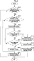
- FIG. 3 is a flowchart illustrating the control process that is executed in the ECU 190 in the present embodiment.
- step (hereinafter, a step will be denoted by S) 100 the ECU 190 determines whether the state of the vehicle 100 enables execution of the contactless charging control.
- the ECU 190 determines that the state of the vehicle 100 enables execution of the contactless charging control (YES in S100)
- the process transitions to S102.
- the ECU 190 determines whether the contactless charging control is planned to be executed as the scheduled charging control.
- the ECU 190 determines that the contactless charging control is planned to be executed as the scheduled charging control, when the predetermined storage area of the memory 192 stores information indicating that the scheduled charging control is planned to be executed, information indicating that execution of the contactless charging control is selected as the scheduled charging control, and the set time.
- the ECU 190 determines that the contactless charging control is planned to be executed as the scheduled charging control (YES in S102)
- the process transitions to S104.
- the ECU 190 executes the sleep control.
- the ECU 190 determines whether the charging connector 310 is connected to the charging inlet 110. When the ECU 190 determines that the charging connector 310 is connected to the charging inlet 110 (YES in S106), the process transitions to S114. When the ECU 190 determines that the charging connector 310 is not connected to the charging inlet 110 (NO in S106), the process transitions to S108.
- the ECU 190 determines whether the time reaches the set time. When the ECU 190 determines that the time reaches the set time (YES in S108), the process transitions to S110.
- the ECU 190 ends the sleep control. In S112, the ECU 190 executes the contactless charging control.
- the ECU 190 cancels planned execution of the scheduled charging control in S114. Specifically, for example, the ECU 190 cancels planned execution of the scheduled charging control by deleting information indicating that the scheduled charging control is planned to be executed, information indicating that execution of the contactless charging control is selected as the scheduled charging control, and the set time stored in the predetermined storage area. In such a case, for example, the ECU 190 may suppress execution of the scheduled charging control by prohibiting execution of the scheduled charging control regardless of information stored in the predetermined storage area. The ECU 190 may cancel planned execution of the scheduled charging control by deleting solely information indicating that the scheduled charging control is planned to be executed.
- the ECU 190 ends the sleep control.
- the ECU 190 executes the contacted charging control.
- the process is finished.
- the ECU 190 determines that the scheduled charging control is not planned to be executed (NO in S102)
- the process transitions to S112, and the contactless charging control is executed immediately.
- the ECU 190 determines that the time does not reach the set time (NO in S108)
- the process returns to S106.
- FIG. 4 is a diagram for describing operation of the ECU 190 in the present embodiment.
- the horizontal axis in FIG. 4 denotes time.
- the vertical axis in FIG. 4 denotes executability of the contactless charging control, whether or not the scheduled charging control is executed, the connection state of the charging connector 310 to the charging inlet 110, whether or not the sleep control is executed, whether or not the contacted charging control is executed, and whether or not the contactless charging control is executed. That is, a change in the availability of contactless charging is illustrated by LN1 in FIG. 4 .
- a change in whether or not the scheduled charging control is executed is illustrated by LN2 and LN2' in FIG. 4 .
- a change in the connection state of the charging connector 310 to the charging inlet 110 is illustrated by LN3 and LN3' in FIG. 4 .
- a change in whether or not the sleep control is executed is illustrated by LN4 and LN4' in FIG. 4 .
- a change in whether or not the contacted charging control is executed is illustrated by LN5 and LN5' in FIG. 4 .
- a change in whether or not the contactless charging control is executed is illustrated by LN6 and LN6' in FIG. 4 .
- contactless charging is planned to be executed as the scheduled charging control, and that the positional relationship between the vehicle 100 and the electric power transmission device 400 does not enable execution of contactless charging.
- the vehicle 100 enters the communication range of the electric power transmission device 400, communication is established between the communication device 180 of the vehicle 100 and the communication unit 402 of the electric power transmission device 400.
- the camera 406 is started, and the image data captured by the camera 406 is transmitted to the vehicle 100.
- the ECU 190 determines that the contactless charging control can be executed (YES in S 100), as illustrated by LN1 in FIG. 4 . Since the contactless charging control is planned to be executed as the scheduled charging control (YES in S102) as illustrated by LN2 in FIG. 4 , the sleep control is executed (S104) as illustrated by LN4 in FIG. 4 .
- the state in which the scheduled charging control is planned to be executed is continued as illustrated by LN2' in FIG. 4 .
- the sleep control is ended (S110) as illustrated by LN4' in FIG. 4
- the contactless charging control is executed (S112) as illustrated by LN6' in FIG. 4 .
- the contacted charging control is not executed as illustrated by LN5' in FIG. 4 .
- the charging connector 310 when the charging connector 310 is connected to the charging inlet 110 when the scheduled charging control that starts the contactless charging control at the set time is planned to be executed, there is a possibility that the user expects charging to be started before the set time.
- charging can be performed as intended by the user by suppressing execution of the scheduled charging control and executing the contacted charging control.
- the contacted charging control since the contacted charging control is started before the set time, the user can recognize that execution of the scheduled charging control is suppressed. Accordingly, an electric vehicle that enables contacted charging and contactless charging and in which charging can be performed by reflecting the user's intention can be provided.
- the vehicle 100 is not particularly limited to an electric vehicle, provided that the vehicle 100 is a vehicle in which a vehicle-mounted electric power storage device can be charged by either contacted charging or contactless charging using an external electric power supply.
- the vehicle 100 may be a hybrid vehicle or a vehicle that uses an engine as a drive source.
- a determination as to whether the state of the vehicle 100 enables execution of the contactless charging control is performed based on the image data of the space above the electric power transmission device 400 captured by the camera 406
- a determination as to whether the state of the vehicle 100 enables execution of the contactless charging control can be performed by, for example, using a switch that outputs an ON signal to the electric power transmission device 400 when being in contact with a wheel of the vehicle 100 at a stoppage of the wheel.
- the ECU 190 may determine that the state of the vehicle 100 enables execution of the contactless charging control.
- the ECU 190 may determine whether the state of the vehicle 100 enables execution of the contactless charging control, using a camera that images the vehicle 100 from above in a parking area. For example, the camera transmits the image data captured from above in the parking area to the electric power transmission device 400. The electric power transmission device 400 transmits the image data received from the camera to the ECU 190. The ECU 190 specifies the position of the vehicle 100 in the parking area from the received image data. When the specified position of the vehicle 100 is within a predetermined range in which electric power can be transferred to the electric power reception device 150 from the electric power transmission device 400, the ECU 190 determines that the state of the vehicle 100 enables execution of the contactless charging control.
- the contacted charging control is executed, by reflecting the user's intention as much as possible, at a time when the charging connector 310 is connected to the charging inlet 110 when the contactless charging control at the set time is planned to be executed as the scheduled charging control
- execution of the contacted charging control is not particularly limited to the time of connection, provided that the contacted charging control is executed at a time before the set time.
- the contacted charging control may be executed after a predetermined time period elapses from the time of connection.
- the predetermined time period may be set as a time period in which a process of notifying the user that contacted charging will be executed is completed.
- the contactless charging control is not particularly limited to magnetic resonance charging control.
- the contactless charging control may employ electromagnetic induction charging control, charging control by receiving a radio wave, and the like.
- the contacted charging control is executed when the charging connector 310 is connected to the charging inlet 110 before the start of the contactless charging control when the scheduled charging control is planned to be executed in a state in which the contactless charging control can be executed
- the following operation may also be performed.
- the ECU 190 may stop the contactless charging control and execute the contacted charging control even when the charging connector 310 is connected to the charging inlet 110 after the start of the contactless charging control (after the set time).
- the contactless charging control is automatically started when the scheduled charging control is not planned to be executed in a state in which the contactless charging control can be executed
- the ECU 190 may ask the user through the touch panel display 170 whether or not to immediately start the contactless charging control when the scheduled charging control is not planned to be executed in a state in which the contactless charging control can be executed.
- the ECU 190 may start the contactless charging control when the ECU 190 receives an instruction to start the contactless charging control from the user through the touch panel display 170.
- a switch that starts the contactless charging control may be disposed in the electric power transmission device 400 or the charging station, and the ECU 190 may start the contactless charging control when the user operates the switch to be in an ON state.
- connection of the charging connector 310 to the charging inlet 110 suppresses execution of the scheduled charging control when the contactless charging control is planned to be executed as the scheduled charging control in a state in which the contactless charging control can be executed
- the following operation may also be performed in such a case.
- an operation of attaching or detaching the charging connector 310 may cause the ECU 190 to suppress execution of the scheduled charging control when the contacted charging control is planned to be executed as the scheduled charging control in a state in which the contacted charging control can be executed while the contactless charging control cannot be executed.
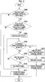
- FIG. 5 is a flowchart illustrating the control process that is executed in the ECU 190 in the modification example.
- the ECU 190 determines whether the state of the vehicle 100 enables execution of the contacted charging control. Specifically, when the charging connector 310 is connected to the charging inlet 110, the ECU 190 determines that the state of the vehicle 100 enables execution of the contacted charging control. A method of determining whether or the charging connector 310 is connected to the charging inlet 110 is the same as described above. Thus, a detailed description of the determination method will not be repeated.
- the ECU 190 determines that the state of the vehicle 100 enables execution of the contacted charging control (YES in S200)
- the process transitions to S202.
- the ECU 190 determines whether the contacted charging control is planned to be executed as the scheduled charging control.
- the ECU 190 determines that the contacted charging control is planned to be executed as the scheduled charging control, when the predetermined storage area of the memory 192 stores information indicating that the scheduled charging control is planned to be executed, information indicating that execution of the contacted charging control is selected as the scheduled charging control, and the set time.
- the ECU 190 determines that the contacted charging control is planned to be executed as the scheduled charging control (YES in S202)
- the process transitions to S204.
- the ECU 190 executes the sleep control.
- the ECU 190 determines whether the operation of attaching or detaching the charging connector 310 is performed.
- the operation of attaching or detaching the charging connector 310 includes a first operation that disconnects the charging connector 310 and the charging inlet 110 from each other, and a second operation that connects the charging connector 310 to the charging inlet 110.
- the operation of attaching or detaching the charging connector 310 may include an operation of repeating the first operation and the second operation a predetermined number of times.
- the ECU 190 determines whether the time reaches the set time. When the ECU 190 determines that the time reaches the set time (YES in S208), the process transitions to S210. In S210, the ECU 190 ends the sleep control. In S212, the ECU 190 executes the contacted charging control.
- the ECU 190 determines that the charging connector 310 is connected to the charging inlet 110 (YES in S206)
- the ECU 190 cancels planned execution of the scheduled charging control in S214. Specifically, the ECU 190 cancels planned execution of the scheduled charging control by deleting at least information, stored in the predetermined storage area, indicating that the scheduled charging control is planned to be executed.
- the ECU 190 ends the sleep control. In S218, the ECU 190 executes the contacted charging control.
- the state of the vehicle 100 does not enable execution of contactless charging, that contacted charging is planned to be executed as the scheduled charging control, and that the charging connector 310 is not connected to the charging inlet 110.
- the ECU 190 determines that the state of the vehicle 100 enables execution of the contacted charging control (YES in S200). Since the contacted charging control is planned to be executed as the scheduled charging control (YES in S202), the sleep control is executed (S204).
- planned execution of the scheduled charging control can be canceled by performing the operation of attaching or detaching the charging connector 310. That is, the user can suppress execution of the scheduled charging control by performing a simple operation of the charging connector 310.
- the modification example may be embodied by combining all or a part of the control process.
- the embodiment disclosed herein is for illustrative purposes from every point of view and should not be considered restrictive.
- the scope of the present disclosure is not disclosed by the description and is disclosed by the claims, and is intended to include all changes made within the equivalent meaning and scope of the claims.
Abstract
Description
- The present disclosure relates to a vehicle that enables both contacted charging and contactless charging of the mounted electric power storage device.
- A vehicle that enables contacted charging and contactless charging is known in the related art. In contacted charging, an electric power storage device mounted in the vehicle is charged using electric power that is received from an electric power supply through an inlet in a state in which a connector disposed in a cable connected to the electric power supply outside the vehicle is connected to the inlet of the vehicle. In contactless charging, the electric power storage device is charged using electric power that is contactlessly received without a connection point from the electric power supply outside the vehicle. As such a vehicle, for example, a configuration that prioritizes contacted charging when the connector is connected to the vehicle during contactless charging, and stops contactless charging is disclosed in Japanese Unexamined Patent Application Publication No.
2013-179723 JP 2013-179723 A 2013-154815 JP 2013-154815 A 2013-146154 JP 2013-146154 A 2013-146148 JP 2013-146148 A 2013-110822 JP 2013-110822 A 2013-126327 JP 2013-126327 A - For example, scheduled charging that starts charging at a set time that is set in advance may be performed in such a vehicle. In such a case, for example, when the connector is connected to the inlet before the start of contactless charging when execution of scheduled charging is planned to start contactless charging at the set time, the content of scheduled charging may be changed to start contacted charging at the set time. However, considering that a user connects the connector to the vehicle regardless of planned execution of scheduled charging that starts contactless charging at the set time, there is a possibility that the user expects charging to be started before the set time. Thus, when the state of waiting for scheduled charging is continued, charging may not be performed as intended by the user.
- The present disclosure provides a vehicle that enables contacted charging and contactless charging and in which charging is performed by reflecting the user's intention.
- An aspect of the present disclosure relates to a vehicle including an electric power storage device, a charging inlet configured to be connected to a charging connector disposed in a charging cable connected to an electric power supply outside the vehicle, an electric power reception device configured to contactlessly receive electric power from the electric power supply, and a controller configured to execute either contacted charging control to charge the electric power storage device using electric power received from the electric power supply through the charging inlet, or contactless charging control to charge the electric power storage device using electric power received from the electric power supply through the electric power reception device. The controller is configured to start charging the electric power storage device when the time reaches a set time set in advance when scheduled charging control that starts charging the electric power storage device at the set time is planned to be executed in a state in which electric power is receivable through either the charging inlet or the electric power reception device. The scheduled charging control includes scheduled charging control that starts the contactless charging control, and scheduled charging control that starts the contacted charging control. The controller is configured to execute the contacted charging control by suppressing execution of the scheduled charging control that starts the contactless charging control, when the charging connector is connected to the charging inlet when the scheduled charging control that starts the contactless charging control at the set time is planned to be executed.
- According to the aspect of the present disclosure, when the charging connector is connected to the charging inlet when the scheduled charging control that starts the contactless charging control at the set time is planned to be executed, there is a possibility that a user expects charging to be started before the set time. Thus, charging can be performed as intended by the user by suppressing execution of the scheduled charging control and executing the contacted charging control. Furthermore, since the contacted charging control is started before the set time, the user can recognize that execution of the scheduled charging control is suppressed.
- In the vehicle according to the aspect of the present disclosure, the scheduled charging control that starts the contactless charging control may be suppressed by canceling planned execution of the scheduled charging control.
- In the vehicle according to the aspect of the present disclosure, the controller may be configured to suppress execution of the scheduled charging control that starts the contacted charging control, when an operation of disconnecting the charging connector and the charging inlet from each other, or an operation of connecting the charging connector to the charging inlet is performed when the scheduled charging control that starts the contacted charging control at the set time is planned to be executed.
- According to the aspect of the present disclosure, the user can suppress execution of the scheduled charging control by performing the operation of disconnecting the charging connector and the charging inlet from each other, or the operation of connecting the charging connector to the charging inlet. That is, the user can suppress execution of the scheduled charging control by performing a simple operation of the charging connector.
- In the vehicle according to the aspect of the present disclosure, the scheduled charging control that starts the contacted charging control may be suppressed by canceling planned execution of the scheduled charging control.
- In the vehicle according to the aspect of the present disclosure, the controller may be configured to determine whether electric power is receivable through the electric power reception device, based on a positional relationship between the electric power reception device and an electric power transmission device configured to transmit electric power to the electric power reception device from the electric power supply outside the vehicle. The controller may be configured to start charging the electric power storage device by the contactless charging control when the time reaches the set time when the scheduled charging control that starts the contactless charging control at the set time is planned to be executed in a state in which the controller determines that electric power is receivable through the electric power reception device. The controller may be configured to stop the contactless charging control when the positional relationship between the electric power reception device and the electric power transmission device is changed to the positional relationship in which the contactless charging control is not executed, or when a state of charge of the electric power storage device reaches a threshold.
- The vehicle according to the aspect of the present disclosure may further include a connection detection circuit configured to detect whether the charging inlet is connected to the charging connector. The controller may be configured to determine whether the connection is made, based on a detection signal that is output from the connection detection circuit. The controller may be configured to start charging the electric power storage device by the contacted charging control when the time reaches the set time when the scheduled charging control that starts the contacted charging control at the set time is planned to be executed in a state in which the controller determines that the contacted charging control is performed when the controller determines that the connection is made. The controller may be configured to stop the contacted charging control when the charging connector is detached from the charging inlet, or when a state of charge of the electric power storage device reaches a threshold.
- According to the aspect of the present disclosure, a vehicle that enables contacted charging and contactless charging and in which charging is performed by reflecting the user's intention can be provided.
- Features, advantages, and technical and industrial significance of exemplary embodiments of the invention will be described below with reference to the accompanying drawings, in which like numerals denote like elements, and wherein:
-
FIG. 1 is a configuration diagram of a vehicle charging system that includes a vehicle according to the present embodiment; -
FIG. 2 is a circuit diagram schematically illustrating an electric power reception system for contactless charging; -
FIG. 3 is a flowchart illustrating a control process that is executed in an ECU in the present embodiment; -
FIG. 4 is a timing chart for describing operation of the ECU in the present embodiment; and -
FIG. 5 is a flowchart illustrating a control process executed in an ECU in a modification example. - Hereinafter, an embodiment of the present disclosure will be described in detail with reference to the drawings. Hereinafter, the same or corresponding parts in the drawings will be designated with the same reference signs, and descriptions of such parts will not be repeated.
-
FIG. 1 is a configuration diagram of avehicle charging system 1 that includes avehicle 100 according to the present embodiment. With reference toFIG. 1 , thevehicle charging system 1 includes thevehicle 100, acharging station 200, acharging cable 300, acharging connector 310, an electricpower transmission device 400, and a systemelectric power supply 500. - The
vehicle 100 is, for example, an electric vehicle that uses a motor generator (not illustrated) as a drive source. - The
vehicle 100 includes acharging inlet 110, an electricpower storage device 120, acharger 130, a power control unit (PCU) 140, an electricpower reception device 150, atouch panel display 170, acommunication device 180, and an electronic control unit (ECU) 190. - The
charging inlet 110 has a shape to which thecharging connector 310 can be connected. Thecharging inlet 110 incorporates a terminal that is electrically connected to thecharger 130. When thecharging connector 310 is connected to thecharging inlet 110, the terminal in thecharging inlet 110 is in contact with a terminal that is incorporated in thecharging connector 310. Accordingly, thecharging inlet 110 can receive electric power from the systemelectric power supply 500 through thecharging station 200, thecharging cable 300, and thecharging connector 310. Electric power received in thecharging inlet 110 is output to thecharger 130. - The electric
power storage device 120 is an electric power storage component that is configured to be capable of being charged or discharged. The electricpower storage device 120 is configured to include a secondary battery such as a lithium ion battery, a nickel-hydrogen battery, or a lead-acid battery, or an electric power storage element such as an electric double-layer capacitor. - The
charger 130 is supplied with alternating current electric power from thecharging station 200 through thecharging inlet 110. Thecharger 130 converts the alternating current electric power into direct current electric power in accordance with a control signal from theECU 190. Thecharger 130 steps up or steps down the output voltage of the direct current electric power to a desired voltage and supplies the direct current electric power to the electricpower storage device 120. Thecharger 130 is configured to include, for example, a rectification circuit that converts the alternating current electric power into direct current electric power, and a converter that steps up or steps down the voltage of the direct current electric power. - The PCU 140 includes an inverter, a converter, and the like. The PCU 140 converts direct current electric power supplied from the electric
power storage device 120 into alternating current electric power and supplies the alternating current electric power to the motor generator in accordance with a control signal from theECU 190. Accordingly, traveling drive power of thevehicle 100 is generated in the motor generator. Alternatively, thePCU 140 converts alternating current electric power generated by a regenerative operation of the motor generator into direct current electric power and supplies the direct current electric power to the electricpower storage device 120. Accordingly, the electricpower storage device 120 can be charged. - The electric
power reception device 150 contactlessly receives alternating current electric power from the electricpower transmission device 400 through an electric power reception coil (that is, without a connection point between the electricpower reception device 150 and the electric power transmission device 400). The electricpower reception device 150 converts the alternating current electric power into direct current electric power, converts the voltage of the direct current electric power into a desired voltage, and supplies the direct current electric power to the electricpower storage device 120. Accordingly, the electricpower storage device 120 can be charged. A detailed configuration of the electricpower reception device 150 will be described below. - The
touch panel display 170, for example, is disposed in a position that can be visually recognized by a user in a driver's seat. Thetouch panel display 170 displays various types of information. The user performs a predetermined operation on thetouch panel display 170. - The
communication device 180 is configured to be capable of wirelessly communicating with acommunication unit 402 of the electricpower transmission device 400 that is present within the communication range of thecommunication device 180. Thecommunication device 180 receives information related to a wireless power transfer (WPT) class supported by the electricpower transmission device 400, information related to the amount of electric power transmitted by the electricpower transmission device 400, and the like from thecommunication unit 402 of the electricpower transmission device 400. For example, communication between thecommunication device 180 and thecommunication unit 402 of the electricpower transmission device 400 is automatically established when thevehicle 100 enters the communication range of thecommunication unit 402 of the electricpower transmission device 400, by authenticating and registering the communication in advance. For example, both of thecommunication device 180 and thecommunication unit 402 are configured with a wireless local area network (LAN) module that complies with Institute of Electrical and Electronics Engineers (IEEE) 802.11. In such a case, thecommunication unit 402 of the electricpower transmission device 400 functions as a master device in the wireless LAN. Communication between thecommunication device 180 and thecommunication unit 402 is established in order to start, for example, contactless electric power transfer. For example, information related to starting/stopping electric power transfer, and information related to the status of electric power reception (the voltage of received electric power, the current of received electric power, the amount of received electric power, and the like) performed by the electricpower reception device 150 are exchanged in communication between thecommunication device 180 and thecommunication unit 402. - The
ECU 190 incorporates a central processing unit (CPU) and amemory 192, not illustrated, and controls each device (thecharger 130, thePCU 140, the electricpower reception device 150, thetouch panel display 170, and the communication device 180) of thevehicle 100 based on information stored in thememory 192 or information from each sensor (not illustrated). Control executed by theECU 190 is not limited to a software process and can also be processed in dedicated hardware (electronic circuit). TheECU 190 has a function as a clock (for example, a radio clock) and has a time acquisition unit (not illustrated) for acquiring the current time. - The charging
station 200 is a device that is disposed outside thevehicle 100 and supplies electric power to thevehicle 100 from the systemelectric power supply 500. The chargingcable 300 is connected to the chargingstation 200. The chargingconnector 310 is disposed at the tip end of the chargingcable 300. - The electric
power transmission device 400 is a device that is disposed outside thevehicle 100 and contactlessly transmits electric power to thevehicle 100 from the systemelectric power supply 500. The electricpower transmission device 400 includes an electricpower transmission unit 404, acamera 406, acontroller 408, and thecommunication unit 402 for communication with thevehicle 100. - The
communication unit 402 exchanges various types of information with thecommunication device 180 after communication with thecommunication device 180 is established as described above. Thecommunication unit 402 is operated in accordance with a control signal from thecontroller 408. - The
camera 406 is an imaging device that captures an image for determining whether the positional relationship between thevehicle 100 and the electricpower transmission device 400 enables contactless charging. Thecamera 406 includes, for example, a fisheye lens and is disposed upward in the electricpower transmission device 400. Thecamera 406 is configured to be capable of imaging, by the fisheye lens, a wide space including the electricpower reception device 150 when thevehicle 100 is moved toward the electricpower transmission device 400. Thecamera 406 images a space above the electricpower transmission device 400 in accordance with a control signal from thecontroller 408. - The electric
power transmission unit 404 is configured with an electric power transmission coil and the like. Hereinafter, a detailed configuration of an electric power reception system configured with the electricpower reception device 150 and the electricpower transmission unit 404 for contactless charging will be described.FIG. 2 is a circuit diagram schematically illustrating the electric power reception system for contactless charging. As illustrated inFIG. 2 , the electricpower reception device 150 includes aresonator 5A and arectifier 5R that converts alternating current electric power received by theresonator 5A into direct current electric power and supplies the direct current electric power to the electricpower storage device 120. Theresonator 5A is an LC resonator and includes an electricpower reception coil 5L and acapacitor 5T that are connected to therectifier 5R. The Q factor of theresonator 5A is greater than or equal to 100. - The electric
power transmission unit 404 includes aresonator 8A and aconverter 8R that is connected to the systemelectric power supply 500. Theconverter 8R adjusts the frequency and voltage of alternating current electric power supplied from the systemelectric power supply 500, and supplies the adjusted alternating current electric power to theresonator 8A. Theresonator 8A is an LC resonator and includes an electricpower transmission coil 8L and acapacitor 8T that are connected to theconverter 8R. The Q factor of theresonator 8A is greater than or equal to 100. The resonant frequency of theresonator 8A substantially matches the resonant frequency of theresonator 5A. - In the configuration described heretofore, either contacted charging control for charging the electric
power storage device 120 mounted in thevehicle 100 using electric power charged from the chargingstation 200 through the chargingcable 300 and the chargingconnector 310, or contactless charging control for charging the electricpower storage device 120 using electric power received from the electricpower transmission device 400 may be executed in thevehicle 100. - In the present embodiment, for example, the
ECU 190 executes executable charging control when the state of thevehicle 100 is changed to enable either the contacted charging control or the contactless charging control. Hereinafter, each charging control will be described. - The
ECU 190, for example, executes the contacted charging control when the chargingconnector 310 is connected to the charginginlet 110. - The
ECU 190, for example, uses a connection detection circuit (not illustrated) to detect whether the chargingconnector 310 is connected to the charginginlet 110. Specifically, the connection detection circuit outputs an ON signal to theECU 190 when the chargingconnector 310 is connected to the charginginlet 110. The connection detection circuit stops outputting the ON signal when the chargingconnector 310 is detached from the charging inlet 110 (that is, when the chargingconnector 310 and the charginginlet 110 are disconnected from each other). For example, the connection detection circuit may be configured with a switch, or may be configured with an electric circuit in which the circuit resistance is changed by connecting the chargingconnector 310 to the charginginlet 110. When theECU 190 receives the ON signal from the connection detection circuit, theECU 190 determines that the chargingconnector 310 is connected to the charging inlet 110 (that is, a state in which the contacted charging control can be executed), and executes the contacted charging control. - When the
ECU 190 starts the contacted charging control, theECU 190 acquires information related to the contacted charging control such as the amount of electric power supplied by the chargingstation 200, from a pilot signal (CPLT) that is received from the chargingstation 200 through the chargingcable 300. TheECU 190 controls thecharger 130 based on the acquired information. TheECU 190 stops the contacted charging control when the chargingconnector 310 is detached from the charginginlet 110, or when the state of charge (SOC) of the electricpower storage device 120 reaches a threshold (an SOC corresponding to the full state of charge). - The
ECU 190 executes the contactless charging control when the positional relationship between thevehicle 100 and the electricpower transmission device 400 is changed to enable execution of the contactless charging control. - The
ECU 190 determines whether the positional relationship between thevehicle 100 and the electricpower transmission device 400 enables execution of the contactless charging control, based on the image data of thecamera 406 transmitted from the electricpower transmission device 400. - The
controller 408 of the electricpower transmission device 400 starts thecamera 406 when communication is established between thecommunication unit 402 and thecommunication device 180. When thecamera 406 is started, thecamera 406 images the space above the electricpower transmission device 400 and transmits the captured image data to thecontroller 408. Thecontroller 408 acquires the image data from thecamera 406 and transmits the acquired image data to theECU 190 through thecommunication unit 402. A mark for specifying the position of the electricpower reception device 150 from the captured image data is disposed in a predetermined location on the lower surface (a surface facing the electric power transmission device 400) of the electricpower reception device 150. - The
ECU 190 specifies the mark from the image data received from the electricpower transmission device 400 and calculates the relative positional relationship (a distance in the horizontal direction and a distance in the vertical direction) between the vehicle 100 (electric power reception device 150) and the electricpower transmission device 400 based on the position and size of the specified mark in the image data. When theECU 190 determines that the positional relationship between thevehicle 100 and the electricpower transmission device 400 enables execution of the contactless charging control (for example, a positional relationship in which the distance in the horizontal direction and the distance in the vertical direction are within a predetermined range) (that is, a state in which the contactless charging control can be executed), theECU 190 executes the contactless charging control in cooperation with the electricpower transmission device 400. - The
ECU 190 stops the contactless charging control when the positional relationship between thevehicle 100 and the electricpower transmission device 400 does not enable execution of the contactless charging control, or when the SOC of the electricpower storage device 120 reaches the threshold. - Even in a state in which the
vehicle 100 can execute the contacted charging control and the contactless charging control, theECU 190 waits until a time that is set in advance (hereinafter, referred to as a set time), when scheduled charging control that starts the charging control at the set time is planned to be executed. When the set time is reached, theECU 190 executes the charging control. - The set time, for example, may be set by the user inputting the set time on the
touch panel display 170, and may be stored in a predetermined storage area of thememory 192. Alternatively, the set time may be stored in advance in the predetermined storage area of thememory 192 of theECU 190. - When the user operates the
touch panel display 170 to request execution of the scheduled charging control at the set time, theECU 190 stores, in thememory 192, information that indicates that a scheduled charging control execution flag is in an ON state (that is, information that indicates that the scheduled charging control is planned to be executed). For example, the user can request execution of the scheduled charging control by selecting any one of the contacted charging control and the contactless charging control by operating thetouch panel display 170. TheECU 190 stores, in thememory 192, information of the type of charging control that is executed as the scheduled charging control in response to the request of the user, along with the set time and information indicating that the scheduled charging control is planned to be executed. - The
ECU 190, for example, executes sleep control until the set time when the predetermined storage area of thememory 192 stores information indicating that the scheduled charging control is planned to be executed, information indicating that execution of the contactless charging control is selected as the scheduled charging control, and the set time in a state in which the contactless charging control can be executed. For example, the sleep control refers to control of setting a part of a plurality of electric devices mounted in thevehicle 100 to a standstill state such that use of a part of the function of thevehicle 100 is restricted, and that the electric power consumption of thevehicle 100 becomes lower than before the restriction. TheECU 190 ends the sleep control and executes the contactless charging control at the set time when the time reaches the set time. - Alternatively, the
ECU 190, for example, executes the sleep control until the set time when the predetermined storage area of thememory 192 stores information indicating that the scheduled charging control is planned to be executed, information indicating that execution of the contacted charging control is selected as the scheduled charging control, and the set time in a state in which the contacted charging control can be executed. TheECU 190 ends the sleep control and executes the contacted charging control at the set time when the time reaches the set time. The sleep control may be ended at a time before the set time. - It is assumed that, for example, the
vehicle 100 having the configuration described heretofore is moved to a position in which the contactless charging control can be executed, and that the position to which thevehicle 100 is moved is a position in which the chargingconnector 310 can be connected to the charginginlet 110, as illustrated inFIG. 1 . Furthermore, it is assumed that the contactless charging control is planned to be executed as the scheduled charging control. Thevehicle 100 waits until the set time at which the contactless charging control is executed. In such a case, when the chargingconnector 310 is connected to the charginginlet 110 before the start of the contactless charging control, theECU 190, for example, may change the control content of the scheduled charging control to start the contacted charging control at the set time. - However, considering that the user connects the charging
connector 310 to the charginginlet 110 before the set time regardless of the contactless charging control that is planned to be executed as the scheduled charging control, there is a possibility that the user expects the contacted charging control to be started before the set time. In such a case, when the state in which the scheduled charging control is planned to be executed is continued, the charging control may not be executed as intended by the user. - In the present embodiment, when the charging
connector 310 is connected to the charginginlet 110 when the contactless charging control is planned to be executed as the scheduled charging control, theECU 190 suppresses execution of the scheduled charging control and executes the contacted charging control before the set time. - When the charging
connector 310 is connected to the charginginlet 110, there is a possibility that the user expects the contacted charging control to be started before the set time. Thus, the charging control can be executed as intended by the user by suppressing execution of the scheduled charging control and executing the contacted charging control before the set time. - A control process that is executed in the
ECU 190 mounted in thevehicle 100 according to the present embodiment will be described with reference toFIG. 3. FIG. 3 is a flowchart illustrating the control process that is executed in theECU 190 in the present embodiment. - In step (hereinafter, a step will be denoted by S) 100, the
ECU 190 determines whether the state of thevehicle 100 enables execution of the contactless charging control. When theECU 190 determines that the state of thevehicle 100 enables execution of the contactless charging control (YES in S100), the process transitions to S102. - In S102, the
ECU 190 determines whether the contactless charging control is planned to be executed as the scheduled charging control. TheECU 190 determines that the contactless charging control is planned to be executed as the scheduled charging control, when the predetermined storage area of thememory 192 stores information indicating that the scheduled charging control is planned to be executed, information indicating that execution of the contactless charging control is selected as the scheduled charging control, and the set time. When theECU 190 determines that the contactless charging control is planned to be executed as the scheduled charging control (YES in S102), the process transitions to S104. - In S104, the
ECU 190 executes the sleep control. In S106, theECU 190 determines whether the chargingconnector 310 is connected to the charginginlet 110. When theECU 190 determines that the chargingconnector 310 is connected to the charging inlet 110 (YES in S106), the process transitions to S114. When theECU 190 determines that the chargingconnector 310 is not connected to the charging inlet 110 (NO in S106), the process transitions to S108. - In S108, the
ECU 190 determines whether the time reaches the set time. When theECU 190 determines that the time reaches the set time (YES in S108), the process transitions to S110. - In S110, the
ECU 190 ends the sleep control. In S112, theECU 190 executes the contactless charging control. - When the
ECU 190 determines that the chargingconnector 310 is connected to the charging inlet 110 (YES in S106), theECU 190 cancels planned execution of the scheduled charging control in S114. Specifically, for example, theECU 190 cancels planned execution of the scheduled charging control by deleting information indicating that the scheduled charging control is planned to be executed, information indicating that execution of the contactless charging control is selected as the scheduled charging control, and the set time stored in the predetermined storage area. In such a case, for example, theECU 190 may suppress execution of the scheduled charging control by prohibiting execution of the scheduled charging control regardless of information stored in the predetermined storage area. TheECU 190 may cancel planned execution of the scheduled charging control by deleting solely information indicating that the scheduled charging control is planned to be executed. - In S116, the
ECU 190 ends the sleep control. InS 118, theECU 190 executes the contacted charging control. - When the
ECU 190 in S100 determines that the state of thevehicle 100 does not enable execution of the contactless charging control (NO in S100), the process is finished. When theECU 190 determines that the scheduled charging control is not planned to be executed (NO in S102), the process transitions to S112, and the contactless charging control is executed immediately. When theECU 190 determines that the time does not reach the set time (NO in S108), the process returns to S106. - Operation of the
ECU 190 mounted in thevehicle 100 according to the present embodiment will be described with reference toFIG. 4 based on the configuration and the flowchart described heretofore.FIG. 4 is a diagram for describing operation of theECU 190 in the present embodiment. - The horizontal axis in
FIG. 4 denotes time. The vertical axis inFIG. 4 denotes executability of the contactless charging control, whether or not the scheduled charging control is executed, the connection state of the chargingconnector 310 to the charginginlet 110, whether or not the sleep control is executed, whether or not the contacted charging control is executed, and whether or not the contactless charging control is executed. That is, a change in the availability of contactless charging is illustrated by LN1 inFIG. 4 . A change in whether or not the scheduled charging control is executed is illustrated by LN2 and LN2' inFIG. 4 . A change in the connection state of the chargingconnector 310 to the charginginlet 110 is illustrated by LN3 and LN3' inFIG. 4 . A change in whether or not the sleep control is executed is illustrated by LN4 and LN4' inFIG. 4 . A change in whether or not the contacted charging control is executed is illustrated by LN5 and LN5' inFIG. 4 . A change in whether or not the contactless charging control is executed is illustrated by LN6 and LN6' inFIG. 4 . - For example, it is assumed that contactless charging is planned to be executed as the scheduled charging control, and that the positional relationship between the
vehicle 100 and the electricpower transmission device 400 does not enable execution of contactless charging. When thevehicle 100 enters the communication range of the electricpower transmission device 400, communication is established between thecommunication device 180 of thevehicle 100 and thecommunication unit 402 of the electricpower transmission device 400. Thecamera 406 is started, and the image data captured by thecamera 406 is transmitted to thevehicle 100. When thevehicle 100 is moved, and theECU 190, based on the received image data, determines that the positional relationship between thevehicle 100 and the electricpower transmission device 400 is changed to enable execution of the contactless charging control, theECU 190 determines that the contactless charging control can be executed (YES in S 100), as illustrated by LN1 inFIG. 4 . Since the contactless charging control is planned to be executed as the scheduled charging control (YES in S102) as illustrated by LN2 inFIG. 4 , the sleep control is executed (S104) as illustrated by LN4 inFIG. 4 . - When the charging
connector 310 is connected to the charginginlet 110 at time T(1) (YES in S106) as illustrated by LN3 inFIG. 4 , planned execution of the scheduled charging control is canceled (S114) as illustrated by LN2 inFIG. 4 . The sleep control is ended (S116) as illustrated by LN4 inFIG. 4 , and the contacted charging control is executed (S118) as illustrated by LN5 inFIG. 4 . - When the charging
connector 310 is not connected to the charginginlet 110 at time T(1) (NO in S106) as illustrated by LN3' inFIG. 4 , the state in which the scheduled charging control is planned to be executed is continued as illustrated by LN2' inFIG. 4 . Thus, when the time reaches the set time at time T(2) (YES in S108), the sleep control is ended (S110) as illustrated by LN4' inFIG. 4 , and the contactless charging control is executed (S112) as illustrated by LN6' inFIG. 4 . Thus, the contacted charging control is not executed as illustrated by LN5' inFIG. 4 . - As described heretofore, in the vehicle according to the present embodiment, when the charging
connector 310 is connected to the charginginlet 110 when the scheduled charging control that starts the contactless charging control at the set time is planned to be executed, there is a possibility that the user expects charging to be started before the set time. Thus, when the chargingconnector 310 is connected to the charginginlet 110, charging can be performed as intended by the user by suppressing execution of the scheduled charging control and executing the contacted charging control. Furthermore, since the contacted charging control is started before the set time, the user can recognize that execution of the scheduled charging control is suppressed. Accordingly, an electric vehicle that enables contacted charging and contactless charging and in which charging can be performed by reflecting the user's intention can be provided. - Hereinafter, a modified example will be described. While the embodiment above illustratively describes the
vehicle 100 as an electric vehicle, thevehicle 100 is not particularly limited to an electric vehicle, provided that thevehicle 100 is a vehicle in which a vehicle-mounted electric power storage device can be charged by either contacted charging or contactless charging using an external electric power supply. For example, thevehicle 100 may be a hybrid vehicle or a vehicle that uses an engine as a drive source. - While, in the embodiment described above, a determination as to whether the state of the
vehicle 100 enables execution of the contactless charging control is performed based on the image data of the space above the electricpower transmission device 400 captured by thecamera 406, a determination as to whether the state of thevehicle 100 enables execution of the contactless charging control can be performed by, for example, using a switch that outputs an ON signal to the electricpower transmission device 400 when being in contact with a wheel of thevehicle 100 at a stoppage of the wheel. For example, when theECU 190 receives, from the electricpower transmission device 400, information that indicates that the ON signal is output from the switch, theECU 190 may determine that the state of thevehicle 100 enables execution of the contactless charging control. Alternatively, theECU 190 may determine whether the state of thevehicle 100 enables execution of the contactless charging control, using a camera that images thevehicle 100 from above in a parking area. For example, the camera transmits the image data captured from above in the parking area to the electricpower transmission device 400. The electricpower transmission device 400 transmits the image data received from the camera to theECU 190. TheECU 190 specifies the position of thevehicle 100 in the parking area from the received image data. When the specified position of thevehicle 100 is within a predetermined range in which electric power can be transferred to the electricpower reception device 150 from the electricpower transmission device 400, theECU 190 determines that the state of thevehicle 100 enables execution of the contactless charging control. - While, in the embodiment described above, the contacted charging control is executed, by reflecting the user's intention as much as possible, at a time when the charging
connector 310 is connected to the charginginlet 110 when the contactless charging control at the set time is planned to be executed as the scheduled charging control, execution of the contacted charging control is not particularly limited to the time of connection, provided that the contacted charging control is executed at a time before the set time. For example, the contacted charging control may be executed after a predetermined time period elapses from the time of connection. For example, the predetermined time period may be set as a time period in which a process of notifying the user that contacted charging will be executed is completed. - While the embodiment describes magnetic resonance charging control as one aspect of the contactless charging control and a configuration for executing the charging control, the contactless charging control is not particularly limited to magnetic resonance charging control. For example, the contactless charging control may employ electromagnetic induction charging control, charging control by receiving a radio wave, and the like.
- While, in the embodiment described above, the contacted charging control is executed when the charging
connector 310 is connected to the charginginlet 110 before the start of the contactless charging control when the scheduled charging control is planned to be executed in a state in which the contactless charging control can be executed, the following operation may also be performed. For example, theECU 190 may stop the contactless charging control and execute the contacted charging control even when the chargingconnector 310 is connected to the charginginlet 110 after the start of the contactless charging control (after the set time). - While, in the embodiment described above, the contactless charging control is automatically started when the scheduled charging control is not planned to be executed in a state in which the contactless charging control can be executed, the following operation may also be performed. For example, the
ECU 190 may ask the user through thetouch panel display 170 whether or not to immediately start the contactless charging control when the scheduled charging control is not planned to be executed in a state in which the contactless charging control can be executed. TheECU 190 may start the contactless charging control when theECU 190 receives an instruction to start the contactless charging control from the user through thetouch panel display 170. Alternatively, a switch that starts the contactless charging control may be disposed in the electricpower transmission device 400 or the charging station, and theECU 190 may start the contactless charging control when the user operates the switch to be in an ON state. - While, in the embodiment described above, connection of the charging
connector 310 to the charginginlet 110 suppresses execution of the scheduled charging control when the contactless charging control is planned to be executed as the scheduled charging control in a state in which the contactless charging control can be executed, the following operation may also be performed in such a case. For example, an operation of attaching or detaching the chargingconnector 310 may cause theECU 190 to suppress execution of the scheduled charging control when the contacted charging control is planned to be executed as the scheduled charging control in a state in which the contacted charging control can be executed while the contactless charging control cannot be executed. - Hereinafter, one example of a control process that is executed in the
ECU 190 in the modification example will be described usingFIG. 5. FIG. 5 is a flowchart illustrating the control process that is executed in theECU 190 in the modification example. - In S200, the
ECU 190 determines whether the state of thevehicle 100 enables execution of the contacted charging control. Specifically, when the chargingconnector 310 is connected to the charginginlet 110, theECU 190 determines that the state of thevehicle 100 enables execution of the contacted charging control. A method of determining whether or the chargingconnector 310 is connected to the charginginlet 110 is the same as described above. Thus, a detailed description of the determination method will not be repeated. When theECU 190 determines that the state of thevehicle 100 enables execution of the contacted charging control (YES in S200), the process transitions to S202. - In S202, the
ECU 190 determines whether the contacted charging control is planned to be executed as the scheduled charging control. TheECU 190 determines that the contacted charging control is planned to be executed as the scheduled charging control, when the predetermined storage area of thememory 192 stores information indicating that the scheduled charging control is planned to be executed, information indicating that execution of the contacted charging control is selected as the scheduled charging control, and the set time. When theECU 190 determines that the contacted charging control is planned to be executed as the scheduled charging control (YES in S202), the process transitions to S204. - In S204, the
ECU 190 executes the sleep control. In S206, theECU 190 determines whether the operation of attaching or detaching the chargingconnector 310 is performed. The operation of attaching or detaching the chargingconnector 310 includes a first operation that disconnects the chargingconnector 310 and the charginginlet 110 from each other, and a second operation that connects the chargingconnector 310 to the charginginlet 110. The operation of attaching or detaching the chargingconnector 310 may include an operation of repeating the first operation and the second operation a predetermined number of times. When theECU 190 determines that the operation of attaching or detaching the chargingconnector 310 is performed (YES in S206), the process transitions to S214. When theECU 190 determines that the operation of attaching or detaching the chargingconnector 310 is not performed (NO in S206), the process transitions to S208. - In S208, the
ECU 190 determines whether the time reaches the set time. When theECU 190 determines that the time reaches the set time (YES in S208), the process transitions to S210. In S210, theECU 190 ends the sleep control. In S212, theECU 190 executes the contacted charging control. - When the
ECU 190 determines that the chargingconnector 310 is connected to the charging inlet 110 (YES in S206), theECU 190 cancels planned execution of the scheduled charging control in S214. Specifically, theECU 190 cancels planned execution of the scheduled charging control by deleting at least information, stored in the predetermined storage area, indicating that the scheduled charging control is planned to be executed. - In S216, the
ECU 190 ends the sleep control. In S218, theECU 190 executes the contacted charging control. - When the
ECU 190 in S200 determines that the state of thevehicle 100 does not enable execution of the contacted charging control (NO in S200), the process is finished. When theECU 190 determines that the scheduled charging control is not planned to be executed (NO in S202), the process transitions to S212, and the contacted charging control is executed immediately. When theECU 190 determines that the time does not reach the set time (NO in S208), the process returns to S206. - Operation of the
ECU 190 in the modification example will be described based on the flowchart described heretofore. - For example, it is assumed that the state of the
vehicle 100 does not enable execution of contactless charging, that contacted charging is planned to be executed as the scheduled charging control, and that the chargingconnector 310 is not connected to the charginginlet 110. When the user connects the chargingconnector 310 to the charging inlet, theECU 190 determines that the state of thevehicle 100 enables execution of the contacted charging control (YES in S200). Since the contacted charging control is planned to be executed as the scheduled charging control (YES in S202), the sleep control is executed (S204). - When the operation of attaching or detaching the charging
connector 310 is performed during execution of the sleep control (YES in S206), planned execution of the scheduled charging control is canceled (S214). The sleep control is ended (S216), and the contacted charging control is executed (S218). - When the operation of attaching or detaching the charging
connector 310 is not performed (NO in S206), and the time reaches the set time (YES in S208), the sleep control is ended (S210), and the contacted charging control is executed (S212). - As described above, when the contacted charging control is planned to be executed as the scheduled charging control in a state in which the contacted charging control can be executed, planned execution of the scheduled charging control can be canceled by performing the operation of attaching or detaching the charging
connector 310. That is, the user can suppress execution of the scheduled charging control by performing a simple operation of the chargingconnector 310. - The modification example may be embodied by combining all or a part of the control process. The embodiment disclosed herein is for illustrative purposes from every point of view and should not be considered restrictive. The scope of the present disclosure is not disclosed by the description and is disclosed by the claims, and is intended to include all changes made within the equivalent meaning and scope of the claims.
Claims (6)
- A vehicle (100) comprising:an electric power storage device (120);a charging inlet (110) configured to be connected to a charging connector (310) disposed in a charging cable (300) connected to an electric power supply outside the vehicle (100);an electric power reception device (150) configured to contactlessly receive electric power from the electric power supply; anda controller configured to execute either contacted charging control to charge the electric power storage device (120) using electric power received from the electric power supply through the charging inlet (110), or contactless charging control to charge the electric power storage device (120) using electric power received from the electric power supply through the electric power reception device (150), wherein:the controller is configured to start charging the electric power storage device (120) when the time reaches a set time set in advance when scheduled charging control that starts charging the electric power storage device (120) at the set time is to be executed and when electric power is receivable through either the charging inlet (110) or the electric power reception device (150);the scheduled charging control includes scheduled charging control that starts the contactless charging control, and scheduled charging control that starts the contacted charging control; andthe controller is configured to execute the contacted charging control by preventing execution of the scheduled charging control that starts the contactless charging control, when the charging connector (310) is connected to the charging inlet (110) when the scheduled charging control that starts the contactless charging control at the set time is to be executed.
- The vehicle (100) according to claim 1, wherein execution of the scheduled charging control that starts the contactless charging control is prevented by canceling planned execution of the scheduled charging control.
- The vehicle (100) according to claim 1, wherein the controller is configured to prevent execution of the scheduled charging control that starts the contacted charging control, when an operation of disconnecting the charging connector (310) and the charging inlet (110) from each other, or an operation of connecting the charging connector (310) to the charging inlet (110) is performed when the scheduled charging control that starts the contacted charging control at the set time is to be executed.
- The vehicle (100) according to claim 3, wherein execution of the scheduled charging control that starts the contacted charging control is prevented by canceling planned execution of the scheduled charging control.
- The vehicle (100) according to claim 1, wherein:the controller is configured to determine whether electric power is receivable through the electric power reception device (150), based on a positional relationship between the electric power reception device (150) and an electric power transmission device (400) configured to transmit electric power to the electric power reception device (150) from the electric power supply outside the vehicle (100);the controller is configured to start charging the electric power storage device (120) by the contactless charging control when the time reaches the set time when the scheduled charging control that starts the contactless charging control at the set time is planned to be executed in a state in which the controller determines that electric power is receivable through the electric power reception device (150); andthe controller is configured to stop the contactless charging control when the positional relationship between the electric power reception device (150) and the electric power transmission device (400) is changed to the positional relationship in which the contactless charging control is not executed, or when a state of charge of the electric power storage device (120) reaches a threshold.
- The vehicle (100) according to claim 1, further comprising a connection detection circuit configured to detect whether the charging inlet (110) is connected to the charging connector (310), wherein:the controller is configured to determine whether the connection is made, based on a detection signal that is output from the connection detection circuit;the controller is configured to start charging the electric power storage device (120) by the contacted charging control when the time reaches the set time when the scheduled charging control that starts the contacted charging control at the set time is to be executed and when the controller determines that the contacted charging control is performed when the controller determines that the connection is made; andthe controller is configured to stop the contacted charging control when the charging connector (310) is detached from the charging inlet (110), or when a state of charge of the electric power storage device (120) reaches a threshold.
Applications Claiming Priority (1)
| Application Number | Priority Date | Filing Date | Title |
|---|---|---|---|
| JP2017020105A JP6589904B2 (en) | 2017-02-07 | 2017-02-07 | vehicle |
Publications (3)
| Publication Number | Publication Date |
|---|---|
| EP3357743A2 true EP3357743A2 (en) | 2018-08-08 |
| EP3357743A3 EP3357743A3 (en) | 2018-08-29 |
| EP3357743B1 EP3357743B1 (en) | 2019-12-18 |
Family
ID=61163578
Family Applications (1)
| Application Number | Title | Priority Date | Filing Date |
|---|---|---|---|
| EP18155125.0A Active EP3357743B1 (en) | 2017-02-07 | 2018-02-05 | Vehicle |
Country Status (5)
| Country | Link |
|---|---|
| US (1) | US10434887B2 (en) |
| EP (1) | EP3357743B1 (en) |
| JP (1) | JP6589904B2 (en) |
| KR (1) | KR102099791B1 (en) |
| CN (1) | CN108394294B (en) |
Families Citing this family (6)
| Publication number | Priority date | Publication date | Assignee | Title |
|---|---|---|---|---|
| JP6897371B2 (en) * | 2017-07-03 | 2021-06-30 | トヨタ自動車株式会社 | Vehicle and power transmission system |
| JP2020167890A (en) * | 2019-03-29 | 2020-10-08 | 株式会社デンソーテン | Charging control device, charging system, and charging method |
| CN111016695B (en) * | 2019-12-23 | 2024-02-27 | 内蒙古快为科技有限公司 | Wireless induction charging system and method for vehicle |
| CN111605416B (en) * | 2020-05-12 | 2021-12-07 | 宁波吉利汽车研究开发有限公司 | Method and system for setting reservation charging and computer readable storage medium |
| JP7294301B2 (en) * | 2020-10-28 | 2023-06-20 | トヨタ自動車株式会社 | Mobile body, server and judgment program |
| CN114148189A (en) * | 2021-12-22 | 2022-03-08 | 沙龙智行科技有限公司 | Wireless charging method and device for electric vehicle, cloud server and storage medium |
Citations (6)
| Publication number | Priority date | Publication date | Assignee | Title |
|---|---|---|---|---|
| JP2013110822A (en) | 2011-11-18 | 2013-06-06 | Toyota Motor Corp | Power transmission system, vehicle, and power supply facility |
| JP2013126327A (en) | 2011-12-15 | 2013-06-24 | Toyota Motor Corp | Power receiving apparatus, vehicle including the same, power transmission apparatus, and power transmission system |
| JP2013146148A (en) | 2012-01-16 | 2013-07-25 | Toyota Motor Corp | Vehicle |
| JP2013146154A (en) | 2012-01-16 | 2013-07-25 | Toyota Motor Corp | Power reception device, power transmission device, and power transmission system |
| JP2013154815A (en) | 2012-01-31 | 2013-08-15 | Toyota Motor Corp | Vehicle and power transmission system |
| JP2013179723A (en) | 2012-02-10 | 2013-09-09 | Sumitomo Electric Ind Ltd | Charge device and charge method |
Family Cites Families (13)
| Publication number | Priority date | Publication date | Assignee | Title |
|---|---|---|---|---|
| US9853488B2 (en) * | 2008-07-11 | 2017-12-26 | Charge Fusion Technologies, Llc | Systems and methods for electric vehicle charging and power management |
| US20110302078A1 (en) * | 2010-06-02 | 2011-12-08 | Bryan Marc Failing | Managing an energy transfer between a vehicle and an energy transfer system |
| CN107089142B (en) * | 2012-01-30 | 2020-02-18 | 丰田自动车株式会社 | Power receiving device for vehicle, power supply apparatus, and power transmission system |
| JP2014107915A (en) * | 2012-11-27 | 2014-06-09 | Nissan Motor Co Ltd | Non-contact power supply system |
| JP2016034169A (en) * | 2012-12-26 | 2016-03-10 | 日産自動車株式会社 | Non-contact power supply device and non-contact power supply system |
| JP6003696B2 (en) * | 2013-02-06 | 2016-10-05 | トヨタ自動車株式会社 | Conversion unit |
| JP5761230B2 (en) * | 2013-02-26 | 2015-08-12 | トヨタ自動車株式会社 | Vehicle charging device |
| JP5979308B2 (en) * | 2013-03-29 | 2016-08-24 | 日産自動車株式会社 | Contactless power supply system |
| JP6217211B2 (en) * | 2013-07-23 | 2017-10-25 | 株式会社Ihi | Non-contact power supply apparatus and system |
| US10899235B2 (en) * | 2014-01-02 | 2021-01-26 | Causam Energy, Inc. | Systems and methods for electric vehicle charging and user interface therefor |
| JP6337709B2 (en) | 2014-09-12 | 2018-06-06 | トヨタ自動車株式会社 | vehicle |
| US20160352113A1 (en) * | 2015-05-29 | 2016-12-01 | GM Global Technology Operations LLC | Electric vehicle charging station |
| CN106347158B (en) * | 2016-09-29 | 2020-08-14 | 北京新能源汽车股份有限公司 | Charger and automobile |
-
2017
- 2017-02-07 JP JP2017020105A patent/JP6589904B2/en active Active
-
2018
- 2018-01-30 KR KR1020180011183A patent/KR102099791B1/en active IP Right Grant
- 2018-02-02 CN CN201810106584.9A patent/CN108394294B/en active Active
- 2018-02-02 US US15/887,579 patent/US10434887B2/en active Active
- 2018-02-05 EP EP18155125.0A patent/EP3357743B1/en active Active
Patent Citations (6)
| Publication number | Priority date | Publication date | Assignee | Title |
|---|---|---|---|---|
| JP2013110822A (en) | 2011-11-18 | 2013-06-06 | Toyota Motor Corp | Power transmission system, vehicle, and power supply facility |
| JP2013126327A (en) | 2011-12-15 | 2013-06-24 | Toyota Motor Corp | Power receiving apparatus, vehicle including the same, power transmission apparatus, and power transmission system |
| JP2013146148A (en) | 2012-01-16 | 2013-07-25 | Toyota Motor Corp | Vehicle |
| JP2013146154A (en) | 2012-01-16 | 2013-07-25 | Toyota Motor Corp | Power reception device, power transmission device, and power transmission system |
| JP2013154815A (en) | 2012-01-31 | 2013-08-15 | Toyota Motor Corp | Vehicle and power transmission system |
| JP2013179723A (en) | 2012-02-10 | 2013-09-09 | Sumitomo Electric Ind Ltd | Charge device and charge method |
Also Published As
| Publication number | Publication date |
|---|---|
| EP3357743A3 (en) | 2018-08-29 |
| EP3357743B1 (en) | 2019-12-18 |
| JP6589904B2 (en) | 2019-10-16 |
| JP2018129901A (en) | 2018-08-16 |
| CN108394294A (en) | 2018-08-14 |
| KR20180091718A (en) | 2018-08-16 |
| US20180222335A1 (en) | 2018-08-09 |
| CN108394294B (en) | 2021-01-12 |
| KR102099791B1 (en) | 2020-04-10 |
| US10434887B2 (en) | 2019-10-08 |
Similar Documents
| Publication | Publication Date | Title |
|---|---|---|
| EP3357743B1 (en) | Vehicle | |
| US10052963B2 (en) | Contactless power transfer system and method of controlling the same | |
| US9878628B2 (en) | Power supply device, vehicle and non-contact power supply system | |
| EP2651008B1 (en) | Wireless power feeding apparatus, vehicle, and method of controlling wireless power feeding system | |
| EP2899059B1 (en) | Contactless charging system, charging station, and method of controlling contactless charging system | |
| EP3089323B1 (en) | Non-contact power transmission device | |
| WO2015097995A1 (en) | Power reception device and vehicle including the same | |
| US10787085B2 (en) | Vehicle, power transmission device, and power feeding system | |
| WO2015076290A1 (en) | Non-contact electric power transmission and reception system | |
| EP2902252B1 (en) | Non-contact electric power transmission system and charging station | |
| JP2015144529A (en) | Non-contact power transmission system and charge station | |
| JP2018133931A (en) | vehicle | |
| JP7040400B2 (en) | vehicle | |
| US20190006878A1 (en) | Vehicle and power transfer system | |
| WO2015075514A1 (en) | Contactless power transfer system, charging station, and vehicle | |
| JP2012217246A (en) | Non-contact charging adapter for vehicle | |
| US20240051408A1 (en) | Vehicle | |
| JP2016178810A (en) | Non-contact power supply system | |
| JP6221699B2 (en) | Vehicle with power receiving unit | |
| CN117465246A (en) | Electric vehicle charging system and method of operating the same | |
| JP2019009855A (en) | vehicle |
Legal Events
| Date | Code | Title | Description |
|---|---|---|---|
| PUAI | Public reference made under article 153(3) epc to a published international application that has entered the european phase |
Free format text: ORIGINAL CODE: 0009012 |
|
| STAA | Information on the status of an ep patent application or granted ep patent |
Free format text: STATUS: REQUEST FOR EXAMINATION WAS MADE |
|
| PUAL | Search report despatched |
Free format text: ORIGINAL CODE: 0009013 |
|
| 17P | Request for examination filed |
Effective date: 20180205 |
|
| AK | Designated contracting states |
Kind code of ref document: A2 Designated state(s): AL AT BE BG CH CY CZ DE DK EE ES FI FR GB GR HR HU IE IS IT LI LT LU LV MC MK MT NL NO PL PT RO RS SE SI SK SM TR |
|
| AX | Request for extension of the european patent |
Extension state: BA ME |
|
| AK | Designated contracting states |
Kind code of ref document: A3 Designated state(s): AL AT BE BG CH CY CZ DE DK EE ES FI FR GB GR HR HU IE IS IT LI LT LU LV MC MK MT NL NO PL PT RO RS SE SI SK SM TR |
|
| AX | Request for extension of the european patent |
Extension state: BA ME |
|
| RIC1 | Information provided on ipc code assigned before grant |
Ipc: B60L 11/18 20060101AFI20180720BHEP |
|
| REG | Reference to a national code |
Ref country code: DE Ref legal event code: R079 Ref document number: 602018001607 Country of ref document: DE Free format text: PREVIOUS MAIN CLASS: B60L0011180000 Ipc: B60L0050500000 |
|
| RIC1 | Information provided on ipc code assigned before grant |
Ipc: B60L 50/50 20190101AFI20190524BHEP |
|
| GRAP | Despatch of communication of intention to grant a patent |
Free format text: ORIGINAL CODE: EPIDOSNIGR1 |
|
| STAA | Information on the status of an ep patent application or granted ep patent |
Free format text: STATUS: GRANT OF PATENT IS INTENDED |
|
| INTG | Intention to grant announced |
Effective date: 20190711 |
|
| GRAS | Grant fee paid |
Free format text: ORIGINAL CODE: EPIDOSNIGR3 |
|
| GRAA | (expected) grant |
Free format text: ORIGINAL CODE: 0009210 |
|
| STAA | Information on the status of an ep patent application or granted ep patent |
Free format text: STATUS: THE PATENT HAS BEEN GRANTED |
|
| AK | Designated contracting states |
Kind code of ref document: B1 Designated state(s): AL AT BE BG CH CY CZ DE DK EE ES FI FR GB GR HR HU IE IS IT LI LT LU LV MC MK MT NL NO PL PT RO RS SE SI SK SM TR |
|
| REG | Reference to a national code |
Ref country code: CH Ref legal event code: EP |
|
| REG | Reference to a national code |
Ref country code: IE Ref legal event code: FG4D |
|
| REG | Reference to a national code |
Ref country code: DE Ref legal event code: R096 Ref document number: 602018001607 Country of ref document: DE |
|
| REG | Reference to a national code |
Ref country code: AT Ref legal event code: REF Ref document number: 1214216 Country of ref document: AT Kind code of ref document: T Effective date: 20200115 |
|
| REG | Reference to a national code |
Ref country code: NL Ref legal event code: MP Effective date: 20191218 |
|
| PG25 | Lapsed in a contracting state [announced via postgrant information from national office to epo] |
Ref country code: LT Free format text: LAPSE BECAUSE OF FAILURE TO SUBMIT A TRANSLATION OF THE DESCRIPTION OR TO PAY THE FEE WITHIN THE PRESCRIBED TIME-LIMIT Effective date: 20191218 Ref country code: BG Free format text: LAPSE BECAUSE OF FAILURE TO SUBMIT A TRANSLATION OF THE DESCRIPTION OR TO PAY THE FEE WITHIN THE PRESCRIBED TIME-LIMIT Effective date: 20200318 Ref country code: GR Free format text: LAPSE BECAUSE OF FAILURE TO SUBMIT A TRANSLATION OF THE DESCRIPTION OR TO PAY THE FEE WITHIN THE PRESCRIBED TIME-LIMIT Effective date: 20200319 Ref country code: NO Free format text: LAPSE BECAUSE OF FAILURE TO SUBMIT A TRANSLATION OF THE DESCRIPTION OR TO PAY THE FEE WITHIN THE PRESCRIBED TIME-LIMIT Effective date: 20200318 Ref country code: SE Free format text: LAPSE BECAUSE OF FAILURE TO SUBMIT A TRANSLATION OF THE DESCRIPTION OR TO PAY THE FEE WITHIN THE PRESCRIBED TIME-LIMIT Effective date: 20191218 Ref country code: LV Free format text: LAPSE BECAUSE OF FAILURE TO SUBMIT A TRANSLATION OF THE DESCRIPTION OR TO PAY THE FEE WITHIN THE PRESCRIBED TIME-LIMIT Effective date: 20191218 Ref country code: FI Free format text: LAPSE BECAUSE OF FAILURE TO SUBMIT A TRANSLATION OF THE DESCRIPTION OR TO PAY THE FEE WITHIN THE PRESCRIBED TIME-LIMIT Effective date: 20191218 |
|
| REG | Reference to a national code |
Ref country code: LT Ref legal event code: MG4D |
|
| PG25 | Lapsed in a contracting state [announced via postgrant information from national office to epo] |
Ref country code: RS Free format text: LAPSE BECAUSE OF FAILURE TO SUBMIT A TRANSLATION OF THE DESCRIPTION OR TO PAY THE FEE WITHIN THE PRESCRIBED TIME-LIMIT Effective date: 20191218 Ref country code: HR Free format text: LAPSE BECAUSE OF FAILURE TO SUBMIT A TRANSLATION OF THE DESCRIPTION OR TO PAY THE FEE WITHIN THE PRESCRIBED TIME-LIMIT Effective date: 20191218 |
|
| PG25 | Lapsed in a contracting state [announced via postgrant information from national office to epo] |
Ref country code: AL Free format text: LAPSE BECAUSE OF FAILURE TO SUBMIT A TRANSLATION OF THE DESCRIPTION OR TO PAY THE FEE WITHIN THE PRESCRIBED TIME-LIMIT Effective date: 20191218 |
|
| PG25 | Lapsed in a contracting state [announced via postgrant information from national office to epo] |
Ref country code: PT Free format text: LAPSE BECAUSE OF FAILURE TO SUBMIT A TRANSLATION OF THE DESCRIPTION OR TO PAY THE FEE WITHIN THE PRESCRIBED TIME-LIMIT Effective date: 20200513 Ref country code: EE Free format text: LAPSE BECAUSE OF FAILURE TO SUBMIT A TRANSLATION OF THE DESCRIPTION OR TO PAY THE FEE WITHIN THE PRESCRIBED TIME-LIMIT Effective date: 20191218 Ref country code: NL Free format text: LAPSE BECAUSE OF FAILURE TO SUBMIT A TRANSLATION OF THE DESCRIPTION OR TO PAY THE FEE WITHIN THE PRESCRIBED TIME-LIMIT Effective date: 20191218 Ref country code: CZ Free format text: LAPSE BECAUSE OF FAILURE TO SUBMIT A TRANSLATION OF THE DESCRIPTION OR TO PAY THE FEE WITHIN THE PRESCRIBED TIME-LIMIT Effective date: 20191218 Ref country code: RO Free format text: LAPSE BECAUSE OF FAILURE TO SUBMIT A TRANSLATION OF THE DESCRIPTION OR TO PAY THE FEE WITHIN THE PRESCRIBED TIME-LIMIT Effective date: 20191218 |
|
| PG25 | Lapsed in a contracting state [announced via postgrant information from national office to epo] |
Ref country code: SM Free format text: LAPSE BECAUSE OF FAILURE TO SUBMIT A TRANSLATION OF THE DESCRIPTION OR TO PAY THE FEE WITHIN THE PRESCRIBED TIME-LIMIT Effective date: 20191218 Ref country code: IS Free format text: LAPSE BECAUSE OF FAILURE TO SUBMIT A TRANSLATION OF THE DESCRIPTION OR TO PAY THE FEE WITHIN THE PRESCRIBED TIME-LIMIT Effective date: 20200418 Ref country code: SK Free format text: LAPSE BECAUSE OF FAILURE TO SUBMIT A TRANSLATION OF THE DESCRIPTION OR TO PAY THE FEE WITHIN THE PRESCRIBED TIME-LIMIT Effective date: 20191218 |
|
| REG | Reference to a national code |
Ref country code: DE Ref legal event code: R097 Ref document number: 602018001607 Country of ref document: DE |
|
| REG | Reference to a national code |
Ref country code: AT Ref legal event code: MK05 Ref document number: 1214216 Country of ref document: AT Kind code of ref document: T Effective date: 20191218 |
|
| PLBE | No opposition filed within time limit |
Free format text: ORIGINAL CODE: 0009261 |
|
| STAA | Information on the status of an ep patent application or granted ep patent |
Free format text: STATUS: NO OPPOSITION FILED WITHIN TIME LIMIT |
|
| REG | Reference to a national code |
Ref country code: BE Ref legal event code: MM Effective date: 20200229 |
|
| PG25 | Lapsed in a contracting state [announced via postgrant information from national office to epo] |
Ref country code: MC Free format text: LAPSE BECAUSE OF FAILURE TO SUBMIT A TRANSLATION OF THE DESCRIPTION OR TO PAY THE FEE WITHIN THE PRESCRIBED TIME-LIMIT Effective date: 20191218 Ref country code: LU Free format text: LAPSE BECAUSE OF NON-PAYMENT OF DUE FEES Effective date: 20200205 Ref country code: ES Free format text: LAPSE BECAUSE OF FAILURE TO SUBMIT A TRANSLATION OF THE DESCRIPTION OR TO PAY THE FEE WITHIN THE PRESCRIBED TIME-LIMIT Effective date: 20191218 Ref country code: DK Free format text: LAPSE BECAUSE OF FAILURE TO SUBMIT A TRANSLATION OF THE DESCRIPTION OR TO PAY THE FEE WITHIN THE PRESCRIBED TIME-LIMIT Effective date: 20191218 |
|
| 26N | No opposition filed |
Effective date: 20200921 |
|
| PG25 | Lapsed in a contracting state [announced via postgrant information from national office to epo] |
Ref country code: SI Free format text: LAPSE BECAUSE OF FAILURE TO SUBMIT A TRANSLATION OF THE DESCRIPTION OR TO PAY THE FEE WITHIN THE PRESCRIBED TIME-LIMIT Effective date: 20191218 Ref country code: AT Free format text: LAPSE BECAUSE OF FAILURE TO SUBMIT A TRANSLATION OF THE DESCRIPTION OR TO PAY THE FEE WITHIN THE PRESCRIBED TIME-LIMIT Effective date: 20191218 |
|
| PG25 | Lapsed in a contracting state [announced via postgrant information from national office to epo] |
Ref country code: IT Free format text: LAPSE BECAUSE OF FAILURE TO SUBMIT A TRANSLATION OF THE DESCRIPTION OR TO PAY THE FEE WITHIN THE PRESCRIBED TIME-LIMIT Effective date: 20191218 Ref country code: IE Free format text: LAPSE BECAUSE OF NON-PAYMENT OF DUE FEES Effective date: 20200205 |
|
| PG25 | Lapsed in a contracting state [announced via postgrant information from national office to epo] |
Ref country code: PL Free format text: LAPSE BECAUSE OF FAILURE TO SUBMIT A TRANSLATION OF THE DESCRIPTION OR TO PAY THE FEE WITHIN THE PRESCRIBED TIME-LIMIT Effective date: 20191218 Ref country code: BE Free format text: LAPSE BECAUSE OF NON-PAYMENT OF DUE FEES Effective date: 20200229 |
|
| REG | Reference to a national code |
Ref country code: DE Ref legal event code: R084 Ref document number: 602018001607 Country of ref document: DE |
|
| REG | Reference to a national code |
Ref country code: GB Ref legal event code: 746 Effective date: 20210929 |
|
| PG25 | Lapsed in a contracting state [announced via postgrant information from national office to epo] |
Ref country code: LI Free format text: LAPSE BECAUSE OF NON-PAYMENT OF DUE FEES Effective date: 20210228 Ref country code: CH Free format text: LAPSE BECAUSE OF NON-PAYMENT OF DUE FEES Effective date: 20210228 |
|
| PG25 | Lapsed in a contracting state [announced via postgrant information from national office to epo] |
Ref country code: TR Free format text: LAPSE BECAUSE OF FAILURE TO SUBMIT A TRANSLATION OF THE DESCRIPTION OR TO PAY THE FEE WITHIN THE PRESCRIBED TIME-LIMIT Effective date: 20191218 Ref country code: MT Free format text: LAPSE BECAUSE OF FAILURE TO SUBMIT A TRANSLATION OF THE DESCRIPTION OR TO PAY THE FEE WITHIN THE PRESCRIBED TIME-LIMIT Effective date: 20191218 Ref country code: CY Free format text: LAPSE BECAUSE OF FAILURE TO SUBMIT A TRANSLATION OF THE DESCRIPTION OR TO PAY THE FEE WITHIN THE PRESCRIBED TIME-LIMIT Effective date: 20191218 |
|
| PG25 | Lapsed in a contracting state [announced via postgrant information from national office to epo] |
Ref country code: MK Free format text: LAPSE BECAUSE OF FAILURE TO SUBMIT A TRANSLATION OF THE DESCRIPTION OR TO PAY THE FEE WITHIN THE PRESCRIBED TIME-LIMIT Effective date: 20191218 |
|
| PGFP | Annual fee paid to national office [announced via postgrant information from national office to epo] |
Ref country code: GB Payment date: 20221230 Year of fee payment: 6 |
|
| PGFP | Annual fee paid to national office [announced via postgrant information from national office to epo] |
Ref country code: FR Payment date: 20230110 Year of fee payment: 6 |
|
| PGFP | Annual fee paid to national office [announced via postgrant information from national office to epo] |
Ref country code: DE Payment date: 20221229 Year of fee payment: 6 |
|
| P01 | Opt-out of the competence of the unified patent court (upc) registered |
Effective date: 20230427 |