EP3357615A1 - Cutting tool and method for producing same - Google Patents
Cutting tool and method for producing same Download PDFInfo
- Publication number
- EP3357615A1 EP3357615A1 EP17851945.0A EP17851945A EP3357615A1 EP 3357615 A1 EP3357615 A1 EP 3357615A1 EP 17851945 A EP17851945 A EP 17851945A EP 3357615 A1 EP3357615 A1 EP 3357615A1
- Authority
- EP
- European Patent Office
- Prior art keywords
- cutting tool
- cutting edge
- cutting
- tool according
- flank face
- Prior art date
- Legal status (The legal status is an assumption and is not a legal conclusion. Google has not performed a legal analysis and makes no representation as to the accuracy of the status listed.)
- Granted
Links
Images


Classifications
-
- B—PERFORMING OPERATIONS; TRANSPORTING
- B23—MACHINE TOOLS; METAL-WORKING NOT OTHERWISE PROVIDED FOR
- B23B—TURNING; BORING
- B23B27/00—Tools for turning or boring machines; Tools of a similar kind in general; Accessories therefor
- B23B27/14—Cutting tools of which the bits or tips or cutting inserts are of special material
-
- B—PERFORMING OPERATIONS; TRANSPORTING
- B23—MACHINE TOOLS; METAL-WORKING NOT OTHERWISE PROVIDED FOR
- B23B—TURNING; BORING
- B23B27/00—Tools for turning or boring machines; Tools of a similar kind in general; Accessories therefor
- B23B27/14—Cutting tools of which the bits or tips or cutting inserts are of special material
- B23B27/141—Specially shaped plate-like cutting inserts, i.e. length greater or equal to width, width greater than or equal to thickness
- B23B27/143—Specially shaped plate-like cutting inserts, i.e. length greater or equal to width, width greater than or equal to thickness characterised by having chip-breakers
-
- B—PERFORMING OPERATIONS; TRANSPORTING
- B23—MACHINE TOOLS; METAL-WORKING NOT OTHERWISE PROVIDED FOR
- B23B—TURNING; BORING
- B23B27/00—Tools for turning or boring machines; Tools of a similar kind in general; Accessories therefor
- B23B27/14—Cutting tools of which the bits or tips or cutting inserts are of special material
- B23B27/18—Cutting tools of which the bits or tips or cutting inserts are of special material with cutting bits or tips or cutting inserts rigidly mounted, e.g. by brazing
- B23B27/20—Cutting tools of which the bits or tips or cutting inserts are of special material with cutting bits or tips or cutting inserts rigidly mounted, e.g. by brazing with diamond bits or cutting inserts
-
- B—PERFORMING OPERATIONS; TRANSPORTING
- B23—MACHINE TOOLS; METAL-WORKING NOT OTHERWISE PROVIDED FOR
- B23C—MILLING
- B23C5/00—Milling-cutters
- B23C5/16—Milling-cutters characterised by physical features other than shape
-
- B—PERFORMING OPERATIONS; TRANSPORTING
- B23—MACHINE TOOLS; METAL-WORKING NOT OTHERWISE PROVIDED FOR
- B23C—MILLING
- B23C5/00—Milling-cutters
- B23C5/16—Milling-cutters characterised by physical features other than shape
- B23C5/165—Milling-cutters characterised by physical features other than shape with chipbreaking or chipdividing equipment
-
- B—PERFORMING OPERATIONS; TRANSPORTING
- B23—MACHINE TOOLS; METAL-WORKING NOT OTHERWISE PROVIDED FOR
- B23D—PLANING; SLOTTING; SHEARING; BROACHING; SAWING; FILING; SCRAPING; LIKE OPERATIONS FOR WORKING METAL BY REMOVING MATERIAL, NOT OTHERWISE PROVIDED FOR
- B23D77/00—Reaming tools
-
- B—PERFORMING OPERATIONS; TRANSPORTING
- B23—MACHINE TOOLS; METAL-WORKING NOT OTHERWISE PROVIDED FOR
- B23D—PLANING; SLOTTING; SHEARING; BROACHING; SAWING; FILING; SCRAPING; LIKE OPERATIONS FOR WORKING METAL BY REMOVING MATERIAL, NOT OTHERWISE PROVIDED FOR
- B23D77/00—Reaming tools
- B23D77/006—Reaming tools with means for lubricating or cooling
-
- B—PERFORMING OPERATIONS; TRANSPORTING
- B23—MACHINE TOOLS; METAL-WORKING NOT OTHERWISE PROVIDED FOR
- B23K—SOLDERING OR UNSOLDERING; WELDING; CLADDING OR PLATING BY SOLDERING OR WELDING; CUTTING BY APPLYING HEAT LOCALLY, e.g. FLAME CUTTING; WORKING BY LASER BEAM
- B23K26/00—Working by laser beam, e.g. welding, cutting or boring
- B23K26/352—Working by laser beam, e.g. welding, cutting or boring for surface treatment
-
- B—PERFORMING OPERATIONS; TRANSPORTING
- B23—MACHINE TOOLS; METAL-WORKING NOT OTHERWISE PROVIDED FOR
- B23K—SOLDERING OR UNSOLDERING; WELDING; CLADDING OR PLATING BY SOLDERING OR WELDING; CUTTING BY APPLYING HEAT LOCALLY, e.g. FLAME CUTTING; WORKING BY LASER BEAM
- B23K26/00—Working by laser beam, e.g. welding, cutting or boring
- B23K26/352—Working by laser beam, e.g. welding, cutting or boring for surface treatment
- B23K26/355—Texturing
-
- B—PERFORMING OPERATIONS; TRANSPORTING
- B23—MACHINE TOOLS; METAL-WORKING NOT OTHERWISE PROVIDED FOR
- B23P—METAL-WORKING NOT OTHERWISE PROVIDED FOR; COMBINED OPERATIONS; UNIVERSAL MACHINE TOOLS
- B23P15/00—Making specific metal objects by operations not covered by a single other subclass or a group in this subclass
- B23P15/28—Making specific metal objects by operations not covered by a single other subclass or a group in this subclass cutting tools
-
- B—PERFORMING OPERATIONS; TRANSPORTING
- B23—MACHINE TOOLS; METAL-WORKING NOT OTHERWISE PROVIDED FOR
- B23P—METAL-WORKING NOT OTHERWISE PROVIDED FOR; COMBINED OPERATIONS; UNIVERSAL MACHINE TOOLS
- B23P15/00—Making specific metal objects by operations not covered by a single other subclass or a group in this subclass
- B23P15/28—Making specific metal objects by operations not covered by a single other subclass or a group in this subclass cutting tools
- B23P15/46—Making specific metal objects by operations not covered by a single other subclass or a group in this subclass cutting tools reaming tools
-
- B—PERFORMING OPERATIONS; TRANSPORTING
- B23—MACHINE TOOLS; METAL-WORKING NOT OTHERWISE PROVIDED FOR
- B23B—TURNING; BORING
- B23B2200/00—Details of cutting inserts
- B23B2200/08—Rake or top surfaces
- B23B2200/081—Rake or top surfaces with projections
-
- B—PERFORMING OPERATIONS; TRANSPORTING
- B23—MACHINE TOOLS; METAL-WORKING NOT OTHERWISE PROVIDED FOR
- B23B—TURNING; BORING
- B23B2200/00—Details of cutting inserts
- B23B2200/12—Side or flank surfaces
- B23B2200/121—Side or flank surfaces with projections
-
- B—PERFORMING OPERATIONS; TRANSPORTING
- B23—MACHINE TOOLS; METAL-WORKING NOT OTHERWISE PROVIDED FOR
- B23B—TURNING; BORING
- B23B2200/00—Details of cutting inserts
- B23B2200/32—Chip breaking or chip evacuation
- B23B2200/321—Chip breaking or chip evacuation by chip breaking projections
-
- B—PERFORMING OPERATIONS; TRANSPORTING
- B23—MACHINE TOOLS; METAL-WORKING NOT OTHERWISE PROVIDED FOR
- B23B—TURNING; BORING
- B23B2200/00—Details of cutting inserts
- B23B2200/32—Chip breaking or chip evacuation
- B23B2200/323—Chip breaking or chip evacuation by chip breaking depressions
-
- B—PERFORMING OPERATIONS; TRANSPORTING
- B23—MACHINE TOOLS; METAL-WORKING NOT OTHERWISE PROVIDED FOR
- B23B—TURNING; BORING
- B23B2226/00—Materials of tools or workpieces not comprising a metal
- B23B2226/12—Boron nitride
-
- B—PERFORMING OPERATIONS; TRANSPORTING
- B23—MACHINE TOOLS; METAL-WORKING NOT OTHERWISE PROVIDED FOR
- B23B—TURNING; BORING
- B23B2226/00—Materials of tools or workpieces not comprising a metal
- B23B2226/12—Boron nitride
- B23B2226/125—Boron nitride cubic [CBN]
-
- B—PERFORMING OPERATIONS; TRANSPORTING
- B23—MACHINE TOOLS; METAL-WORKING NOT OTHERWISE PROVIDED FOR
- B23B—TURNING; BORING
- B23B2226/00—Materials of tools or workpieces not comprising a metal
- B23B2226/31—Diamond
- B23B2226/315—Diamond polycrystalline [PCD]
-
- B—PERFORMING OPERATIONS; TRANSPORTING
- B23—MACHINE TOOLS; METAL-WORKING NOT OTHERWISE PROVIDED FOR
- B23C—MILLING
- B23C2200/00—Details of milling cutting inserts
- B23C2200/12—Side or flank surfaces
- B23C2200/121—Side or flank surfaces with projections
-
- B—PERFORMING OPERATIONS; TRANSPORTING
- B23—MACHINE TOOLS; METAL-WORKING NOT OTHERWISE PROVIDED FOR
- B23C—MILLING
- B23C2200/00—Details of milling cutting inserts
- B23C2200/32—Chip breaking or chip evacuation
- B23C2200/323—Chip breaking or chip evacuation by chip-breaking projections
-
- B—PERFORMING OPERATIONS; TRANSPORTING
- B23—MACHINE TOOLS; METAL-WORKING NOT OTHERWISE PROVIDED FOR
- B23C—MILLING
- B23C2226/00—Materials of tools or workpieces not comprising a metal
- B23C2226/12—Boron nitride
-
- B—PERFORMING OPERATIONS; TRANSPORTING
- B23—MACHINE TOOLS; METAL-WORKING NOT OTHERWISE PROVIDED FOR
- B23C—MILLING
- B23C2226/00—Materials of tools or workpieces not comprising a metal
- B23C2226/12—Boron nitride
- B23C2226/125—Boron nitride cubic [CBN]
-
- B—PERFORMING OPERATIONS; TRANSPORTING
- B23—MACHINE TOOLS; METAL-WORKING NOT OTHERWISE PROVIDED FOR
- B23C—MILLING
- B23C2226/00—Materials of tools or workpieces not comprising a metal
- B23C2226/31—Diamond
- B23C2226/315—Diamond polycrystalline [PCD]
-
- B—PERFORMING OPERATIONS; TRANSPORTING
- B23—MACHINE TOOLS; METAL-WORKING NOT OTHERWISE PROVIDED FOR
- B23D—PLANING; SLOTTING; SHEARING; BROACHING; SAWING; FILING; SCRAPING; LIKE OPERATIONS FOR WORKING METAL BY REMOVING MATERIAL, NOT OTHERWISE PROVIDED FOR
- B23D2277/00—Reaming tools
- B23D2277/24—Materials of the tool or the intended workpiece, methods of applying these materials
- B23D2277/2435—Cubic boron nitride [CBN]
Definitions
- the present disclosure relates to a cutting tool and a manufacturing method thereof.
- the present application claims the priority benefit of Japanese Patent Application No. 2016-246683 filed on December 20, 2016 , the contents of which are incorporated herein by reference in its entirety.
- Japanese Patent Laying-Open No. 2013-212572 discloses a cutting tool.
- the cutting tool disclosed in PTD 1 includes a cutting edge, and a rake face contiguous to the cutting edge.
- the rake face is provided with a surface texture containing a plurality of recesses.
- the recesses are provided intermittently in the chip discharge direction (the direction substantially perpendicular to the cutting edge).
- PTD 1 Japanese Patent Laying-Open No. 2013-212572
- a cutting tool includes a cutting edge portion which contains at least one of cubic boron nitride and polycrystalline diamond.
- the cutting edge portion includes a flank face, a negative land contiguous to the flank face, and a cutting edge formed by a ridgeline between the flank face and the negative land.
- At least one of the negative land and the flank face is provided with a plurality of recesses and a projection. The projection is formed by arranging the edges of adjacent recesses in contact with each other.
- the present disclosure has been made in view of the above-mentioned problems in the prior art. More specifically, the present disclosure provides a cutting tool with reduced cutting resistance and a method for manufacturing the cutting tool.
- the cutting tool of an aspect of the present disclosure it is possible to reduce the cutting resistance.
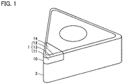
- Fig. 1 is a perspective view illustrating a cutting tool according to the first embodiment.
- the cutting tool according to the first embodiment is, for example, a cutting insert.
- the cutting tool according to the first embodiment is not limited to the cutting insert.
- the cutting tool according to the first embodiment may be, for example, an end mill or a reamer.
- the cutting tool according to the first embodiment includes a cutting edge portion 1.
- the cutting edge portion 1 includes a flank face 11, a negative land 12, and a cutting edge 13.
- the negative land 12 is contiguous to a top face 14 so as to form a negative angle with respect to the top face 14.
- the expression that the negative land 12 forms a negative angle with respect to the top face 14 means that in a state where the top face 14 faces upward and the cutting edge 13 faces leftward, the negative land 12 rotates counterclockwise with respect to the top face 14.
- the negative land 12 and the top face 14 constitute a rake face of the cutting tool according to the first embodiment.
- the negative land 12 is contiguous to the flank face 11.
- the cutting edge 13 is formed by a ridge line between the flank face 11 and the negative land 12.
- the cutting edge portion 1 is a part of the cutting edge chip 10 made of a sintered material containing at least one of cubic boron nitride (CBN) and polycrystalline diamond (PCD), for example.
- the cutting edge portion 1 may be a part of a cutting tool made of a sintered material containing at least one of CBN and PCD.
- the cutting edge portion 1 may be a part of a cutting tool made of a base material such as cemented carbide and at least one of CBN and PCD coated on the surface of the base material.
- the cutting edge portion 1 may only need to contain one of CBN and PCD on at least its surface.
- the volume ratio of CBN, the volume ratio of PCD or the total volume ratio of CBN and PCD contained in the cutting edge portion 1 is preferably 20 volume% or more. If the cutting edge portion 1 is a part of the cutting edge chip 10 made of a sintered material containing at least one of CBN and PCD, the cutting edge chip 10 is attached to a base metal 2 made of cemented carbide or the like via brazing, for example.
- Fig. 2A is an enlarged plan view illustrating a negative land of the cutting tool according to the first embodiment.
- Fig. 2B is an enlarged view illustrating a main part of Fig. 2A .
- Fig. 3 is a cross-sectional view taken along line III-III of Fig. 2A .
- Fig. 4 is a cross-sectional view taken along line IV-IV of Fig. 2A . It should be noted that line III-III is in the same direction as a first direction DR1 to be described later, and line IV-IV is in the same direction as a second direction DR2 to be described later.
- a plurality of recesses 15 are provided on the negative land 12.
- the negative land 12 is recessed where a recess 15 is provided.
- the plurality of recesses 15 are arranged in such a manner that no flat surface is present between adjacent recesses 15.
- each recess 15 has an edge 15a, and the edges 15a of the adjacent recesses 15 are contiguous to each other.
- the plurality of recesses 15 are arranged, for example, in a zigzag manner.
- the plurality of recesses 15 may be provided in such a manner that parts of the adjacent recesses 15 circular in plan view are sequentially overlapped with each other (the overlapped portions are indicated by dotted lines in Fig. 2B ). As to be described later, a projection 16 is formed in the overlapped portion.
- a plurality of recesses 15 are arranged both in column along the first direction DR1 and in row along the second direction DR2, and the adjacent recesses 15 are contiguous to each other.
- the first direction DR1 is a direction intersecting the cutting edge 13.
- the first direction DR1 is preferably orthogonal to the cutting edge 13.
- the second direction DR2 is a direction parallel to the cutting edge 13.
- the second direction DR2 may be orthogonal to the first direction DR1.
- the recesses 15 provided closest to the cutting edge 13 are arranged to be separated from the cutting edge 13. It is preferable that the recesses 15 provided closest to the cutting edge 13 and the cutting edge 13 are separated by a distance DIS.
- the distance DIS is preferably 5 ⁇ m or less.
- the recess 15 is circular or elliptical in cross section, but the shape of the recess 15 in cross section is not limited thereto.
- the recess 15 has a first width W1 in the first direction DR1.
- the first width W1 is the maximum width of the recess 15 in the first direction DR1.
- the first width W1 is preferably greater than 10 ⁇ m and less than 100 ⁇ m.
- the recess 15 has a second width W2 in the second direction DR2.
- the second width W2 is the maximum width of the recess 15 in the second direction DR2.
- the second width W2 is preferably not less than the first width W1 and not more than ten times of the first width W1.
- the recess 15 has a depth D.
- the depth D is the distance between the surface of a portion of the negative land 12 where neither the recess 15 nor the projection 16 is provided and the bottom of the recess 15.
- the depth D is preferably 0.05 ⁇ m or more and 20 ⁇ m or less.
- the arithmetic average roughness Ra of the surface of the recess 15 is preferably 0.05 ⁇ m or more and 1.5 ⁇ m or less.
- the arithmetic average roughness Ra of the surface of the recess 15 is measured by using a laser displacement meter.
- the negative land 12 is provided with a projection 16. It is preferable that a plurality of projections 16 are provided.
- the projection 16 projects in a direction intersecting the negative land 12.
- the projection 16 is formed by arranging the edges 15a of the adjacent recesses 15 in contact with each other. From another viewpoint, the projection 16 is formed in a portion where the adjacent recesses 15 are partly overlapped in plan view. Therefore, the projection 16 is provided in the region where the plurality of recesses 15 are formed. Since the projection 16 is formed by arranging the edges 15a of the adjacent recesses 15 in contact with each other (it is formed in a portion where the adjacent recesses 15, each of which is circular in plan view, are partially overlapped), it is sharp at a tip 16a. In other words, the projection 16 has no flat surface at the tip 16a.
- the projection 16 is formed by arranging the edges 15a of the adjacent recesses 15 in contact with each other, the tip 16 a of the projection 16 matches the edge 15a of the recess 15. Since the projection 16 contains at least one of CBN and PCD, it is less prone to be worn due to the contact with the workpiece as compared with the case where the projection 16 is made of cemented carbide or the like.
- the projection 16 includes a portion extending in a direction orthogonal to the first direction DR1. Since the first direction DR1 is a direction intersecting the cutting edge 13, the projection 16 includes a portion extending in a direction intersecting the direction orthogonal to the cutting edge 13.
- Fig. 5 is a process chart illustrating the method for manufacturing the cutting tool according to the first embodiment. As illustrated in Fig. 5 , the manufacturing method includes a cutting edge portion forming step S1 and a texture forming step S2.
- Fig. 6 is a schematic view illustrating a machining apparatus used in the method for manufacturing the cutting tool according to the first embodiment.
- the machining apparatus 3 used in the method for manufacturing the cutting tool according to the first embodiment includes a light source 31, a scanner head 32, and a machining stage 33.
- the light source 31 supplies laser L to the scanner head 32.
- a workpiece W is placed on the machining stage 33.
- the scanner head 32 scans the surface of the workpiece W with laser L supplied from the light source 31.
- the scanner head 32 is, for example, a galvanometer scanner.
- the texture forming step S2 is performed by using the machining apparatus 3. It is preferable that the cutting edge portion forming step S1 is also performed by using the machining apparatus 3. In other words, it is preferable that both the cutting edge portion forming step S1 and the texture forming method are performed through the irradiation of laser L.
- Fig. 7 is a cross-sectional view illustrating a portion in the vicinity of the cutting edge portion of the cutting tool in the cutting edge portion forming step according to the first embodiment.
- the cutting edge portion 1 having the flank face 11, the negative land 12 and the cutting edge 13 is formed in the cutting edge portion forming step S1.
- the formation of the cutting edge portion 1 having the flank face 11, the negative land 12 and the cutting edge 13 is carried out by irradiating laser L supplied from the light source 31 on the surface of the workpiece W (the face that will become the flank face 11 and the negative land 12 after machining) via the scanner head 32.
- Fig. 8 is a cross-sectional view illustrating a portion in the vicinity of the cutting edge portion of the cutting tool in the texture forming step according to the first embodiment.
- the texture forming step S2 is performed by irradiating laser L supplied from the light source 31 on the negative land 12 via the scanner head 32.
- Fig. 9 is an enlarged top view illustrating the cutting tool in the texture forming step according to the first embodiment.
- the scanning range of laser L is indicated by a dotted line.
- laser L when forming each of the recesses 15, laser L is made to scan the negative land 12 in a circular pattern in plan view.
- laser L is irradiated in such a manner that the irradiation range of laser L partially overlaps with each other.
- the projection 16 is formed in the overlapping region.
- the projection 16 with a sharp tip 16a is formed in the region where the plurality of recesses 15 are formed, so that the negative land 12 has no flat portion between the adjacent recesses 15.
- the plurality of recesses 15 are provided on the negative land 12, and the plurality of recesses 15 are arranged in such a manner that the edges 15a of the adjacent recesses 15 are in contact with each other. Therefore, in the cutting tool according to the first embodiment, no flat surface is present between the adjacent recesses 15, which reduces the contact area between the chips cut from the workpiece and the negative land 12.
- the projection 16 is provided on the negative land 12.
- the cutting tool according to the first embodiment not only the cutting edge 13 but also the projection 16 functions as a cutting edge. Therefore, in the cutting tool according to the first embodiment, the sharpness of the cutting tool is improved. As a result, according to the cutting tool according to the first embodiment, the cutting resistance is reduced.
- the cutting fluid is likely to enter the negative land 12. Therefore, in the cutting tool according to the first embodiment, the cooling effect by the cutting fluid is improved.
- the recess 15 located closest to the cutting edge 13 is separated from the cutting edge 13, since the negative land 12 is recessed where each recess 15 is provided, the recess 15 functions as a chip breaker. Accordingly, it is possible to break chips finely, improving the chip disposability of the cutting tool.
- the depth D of the recess 15 is deep, the cutting fluid is more easily to enter the negative land, and thereby, the cooling effect is further improved. However, if the depth of the recess 15 is too deep, the projection 16 becomes too sharp, which makes it easy to break. Therefore, when the depth D of the recessed portion is 0.05 ⁇ m or more and 20 ⁇ m or less, it is possible to prevent the projection 16 from breaking while improving the cooling effect of the cutting tool.
- the arithmetic average roughness Ra of the surface of the recess 15 is 0.05 ⁇ m or more and 1.5 ⁇ m or less, chips cut from the workpiece are less likely to adhere to the surface of the recess 15. Accordingly, it is possible to suppress the adhesion of chips to the workpiece.
- the distance DIS between the recess 15 located closest to the cutting edge 13 and the cutting edge 13 is large, when the cutting tool according to the first embodiment is used with a small cut, the recess 15 and the workpiece will not contact each other.
- the distance DIS between the recess 15 located closest to the cutting edge 13 and the cutting edge 13 is 5 ⁇ m or less, it is possible to reduce the cutting resistance even when the cutting is performed with a minute cut.
- the cutting tool of the first embodiment when performing not only the texture forming step S2 but also the cutting edge portion forming step S1 by irradiating laser L, there is no need to move the workpiece W during the process (it is unnecessary to perform the positioning of the workpiece when transferring it from the cutting edge forming step S1 to the texture forming step S2). Accordingly, it is possible to form the recess 15 accurately in relation to the cutting edge 13. As a result, it is possible to make the distance DIS between the recess 15 located closest to the cutting edge 13 and the cutting edge 13 equal to 5 ⁇ m or less, for example.
- the cutting tool according to the second embodiment includes a cutting edge portion 1.
- the cutting edge portion 1 includes a flank face 11, a negative land 12, a cutting edge 13 formed by ridgelines of the flank face 11 and the negative land 12.
- the cutting edge portion 1 contains at least one of CBN and PCD. In these respects, the cutting tool according to the second embodiment is the same as the cutting tool according to the first embodiment.
- Fig. 10 is an enlarged plan view illustrating the flank face of the cutting tool according to the second embodiment. As illustrated in Fig. 10 , in the cutting tool according to the second embodiment, the recess 15 and the projection 16 are provided on the flank face 11. In this respect, the cutting tool according to the second embodiment is the same as the cutting tool according to the first embodiment.
- the configuration of the recess 15 and the projection 16 in the cutting tool according to the second embodiment, except that they are not provided on the negative land 12 but on the flank face 11, are the same as the configuration of the recess 15 and the projection 16 in the cutting tool according to the first embodiment.
- a plurality of recesses 15 are provided in the flank face 11 such that the edges 15a of the adjacent recesses 15 are in contact with each other, and the projection 16 is formed by arranging the edges 15a of the adjacent recesses 15 in contact with each other.
- the method for manufacturing the cutting tool according to the second embodiment is similar to the method for manufacturing the cutting tool according to the first embodiment in that it includes a cutting edge portion forming step S1 and a texture forming step S2.
- the texture forming step S2 in the method for manufacturing the cutting tool according to the second embodiment is different from the texture forming step S2 in the method for manufacturing the cutting tool according to the first embodiment in that the recess 15 is formed on the flank face 11 by irradiating the flank face 11 with laser L.
- a plurality of recesses 15 are provided on the flank face 11, and the plurality of recesses 15 are arranged so that the edges 15a of the adjacent recesses 15 are in contact with each other. Therefore, in the cutting tool according to the second embodiment, no flat surface is present between adjacent recesses 15, which reduces the contact area between the surface of the workpiece and the flank face 11.
- the cutting fluid is likely to enter the flank face 11. Therefore, according to the cutting tool according to the second embodiment, it is possible to reduce the cutting resistance and improve the cooling effect by the cutting fluid.
- the cutting tool according to the second embodiment includes a cutting edge portion 1.
- the cutting edge portion 1 includes a flank face 11, a negative land 12, a cutting edge 13 formed by ridgelines of the flank face 11 and the negative land 12.
- the cutting edge portion 1 contains at least one of CBN and PCD.
- the cutting tool according to the third embodiment is the same as the cutting tool according to the first embodiment and the cutting tool according to the second embodiment.
- the recess 15 and the projection 16 are provided on the flank face 11.
- the cutting tool according to the third embodiment is different from the cutting tool according to the first embodiment.
- the recess 15 and the projection 16 are also provided on the negative land 12.
- the cutting tool according to the third embodiment is different from the cutting tool according to the second embodiment.
- the cutting tool according to the third embodiment has a configuration in which the cutting tool according to the first embodiment and the cutting tool according to the second embodiment are combined.
- the method for manufacturing a cutting tool according to the third embodiment is similar to the method for manufacturing a cutting tool according to the first embodiment and the method for manufacturing a cutting tool according to the second embodiment in that it includes a cutting edge portion forming step S1 and a texture forming step S2.
- the texture forming step S2 in the method for manufacturing the cutting tool according to the third embodiment is different from the texture forming step S2 in the method for manufacturing the cutting tool according to the first embodiment and the method for manufacturing the cutting tool according to the second embodiment in that both the flank face 11 and the negative land 12 are irradiated with laser L so that the recesses 15 are formed on both the flank face 11 and the negative land 12.
- the cutting tool according to the third embodiment has a configuration in which the cutting tool according to the first embodiment and the cutting tool according to the second embodiment are combined. Therefore, according to the cutting tool of the third embodiment, it is possible to reduce the cutting resistance and improve the cooling effect by the cutting fluid.
Landscapes
- Engineering & Computer Science (AREA)
- Mechanical Engineering (AREA)
- Physics & Mathematics (AREA)
- Optics & Photonics (AREA)
- Plasma & Fusion (AREA)
- Cutting Tools, Boring Holders, And Turrets (AREA)
- Milling Processes (AREA)
- Laser Beam Processing (AREA)
Abstract
Description
- The present disclosure relates to a cutting tool and a manufacturing method thereof. The present application claims the priority benefit of Japanese Patent Application No.
2016-246683 filed on December 20, 2016 - As a conventional cutting tool, Japanese Patent Laying-Open No.
2013-212572 PTD 1 includes a cutting edge, and a rake face contiguous to the cutting edge. The rake face is provided with a surface texture containing a plurality of recesses. The recesses are provided intermittently in the chip discharge direction (the direction substantially perpendicular to the cutting edge). With such a configuration, it is possible for the cutting tool described inPTD 1 to greatly reduce the cutting force and the thrust force, and it is possible for it to efficiently discharge relatively thin chips. - PTD 1: Japanese Patent Laying-Open No.
2013-212572 - A cutting tool according to an aspect of the present disclosure includes a cutting edge portion which contains at least one of cubic boron nitride and polycrystalline diamond. The cutting edge portion includes a flank face, a negative land contiguous to the flank face, and a cutting edge formed by a ridgeline between the flank face and the negative land. At least one of the negative land and the flank face is provided with a plurality of recesses and a projection. The projection is formed by arranging the edges of adjacent recesses in contact with each other.
-
-
Fig. 1 is a perspective view illustrating a cutting tool according to a first embodiment; -
Fig. 2A is an enlarged plan view illustrating a negative land of the cutting tool according to the first embodiment; -
Fig. 2B is an enlarged view illustrating a main part ofFig. 2A ; -
Fig. 3 is a cross-sectional view taken along line III-III ofFig. 2A ; -
Fig. 4 is a cross-sectional view taken along line IV-IV ofFig. 2A ; -
Fig. 5 is a process chart illustrating a method for manufacturing the cutting tool according to the first embodiment. -
Fig. 6 is a schematic view illustrating a machining apparatus used in the method for manufacturing the cutting tool according to the first embodiment; -
Fig. 7 is a cross-sectional view illustrating a portion in the vicinity of the cutting edge portion of the cutting tool in the cutting edge portion forming step according to the first embodiment; -
Fig. 8 is a cross-sectional view illustrating a portion in the vicinity of the cutting edge portion of the cutting tool in the texture forming step according to the first embodiment; -
Fig. 9 is an enlarged top view illustrating the cutting tool in the texture forming step according to a first embodiment; and -
Fig. 10 is an enlarged plan view illustrating a flank face of the cutting tool according to a second embodiment. - In consideration of the difficulty in cutting a workpiece, it can not be said that the cutting resistance of the cutting tool disclosed in
PTD 1 is sufficiently low, and there is a room left for reducing the cutting resistance. - The present disclosure has been made in view of the above-mentioned problems in the prior art. More specifically, the present disclosure provides a cutting tool with reduced cutting resistance and a method for manufacturing the cutting tool.
- According to the cutting tool of an aspect of the present disclosure, it is possible to reduce the cutting resistance.
- First, aspects of the present disclosure will be described hereinafter.
- (1) A cutting tool according to one aspect of the present disclosure includes a cutting edge portion which contains at least one of cubic boron nitride and polycrystalline diamond. The cutting edge portion includes a flank face, a negative land contiguous to the flank face, and a cutting edge formed by a ridgeline between the flank face and the negative land. At least one of the negative land and the flank face is provided with a plurality of recesses and a projection. The projection is formed by arranging the edges of adjacent recesses in contact with each other. In the present disclosure, the expression that "at least one of the negative land and the flank face is provided with a plurality of recesses and a projection" means that there are 3 possibilities for providing the plurality of recesses and the projection, specifically, the plurality of recesses and the projection are provided only on the negative land (without being provided on the flank face at the same time), the plurality of recesses and the projection are provided only on the flank face (without being provided on the negative land at the same time), the plurality of recesses and the projection are provided both on the negative land and on the flank face.
According to the cutting tool described in the above (1), it is possible to reduce the cutting resistance. Further, according to the cutting tool described in the above (1), it is possible to improve the cooling effect by the cutting fluid. - (2) In the cutting tool described in the above (1), the plurality of recesses and the projection may be provided only on the negative land. According to the cutting tool described in the above (2), it is possible to reduce the cutting resistance of the negative land.
- (3) In the cutting tool described in the above (2), a recess of the plurality of recesses which is provided closest to the cutting edge may be separated by a distance from the cutting edge. According to the cutting tool described in the above (3), it is possible to break the chips finely.
- (4) In the cutting tool described in the above (1), the plurality of recesses and the projection may be provided only on the flank face. According to the cutting tool described in the above (4), it is possible to reduce the cutting resistance of the flank face.
- (5) In the cutting tool described in the above (1), the plurality of recesses may be provided on both the negative land and the flank face. According to the cutting tool described in the above (5), it is possible to reduce the cutting resistance of both the negative land and the flank face.
- (6) In the cutting tools described in the above (1) to (5), the depth of each recess may be 0.05 µm or more and 20 µm or less. According to the cutting tool described in the above (6), it is possible to prevent the projections from getting fractured while improving the cooling effect by the cutting fluid.
- (7) In the cutting tools described in the above (1) to (6), the arithmetic average roughness of the surface of each recess may be 0.05 µm or more and 1.5 µm or less. According to the cutting tool described in the above (7), it is possible to suppress the adhesion of chips cut from the workpiece to the recess.
- (8) In the above cutting tools (1) to (7), the distance between a recess of the plurality of recesses which is provided closest to the cutting edge and the cutting edge may be 5 µm or less. According to the cutting tool described in the above (8), it is possible to reduce the cutting resistance even when the cutting is performed with a small cut.
- (9) A method for manufacturing a cutting tool according to one aspect of the present disclosure is a method for manufacturing a cutting tool including a cutting edge portion which contains at least one of cubic boron nitride and polycrystalline diamond. The cutting edge portion includes a flank face, a negative land contiguous to the flank face, and a cutting edge formed by a ridgeline between the flank face and the negative land. The method for manufacturing a cutting tool according to one aspect of the present disclosure includes a step of irradiating at least one of the negative land and the flank face with laser so as to form a plurality of recesses on the surface irradiated with laser and a plurality of projection formed by arranging the edges of adjacent recesses in contact with each other. According to the manufacturing method described in the above (9), it is possible to obtain a cutting tool with reduced cutting resistance.
- (10) The method for manufacturing a cutting tool according to (9) may further include a step of irradiating the cutting tool with laser so as to form the flank face, the negative land and the cutting edge. According to the manufacturing method described in the above (10), it is possible to arrange the recesses accurately with respect to the cutting edge.
- Hereinafter, embodiments of the present disclosure will be described in detail with reference to the drawings. It should be noted that in the drawings, the same or corresponding parts are denoted by the same reference numerals. In addition, at least some of the embodiments described below may be arbitrarily combined.
- Hereinafter, the configuration of a cutting tool according to a first embodiment will be described.
-
Fig. 1 is a perspective view illustrating a cutting tool according to the first embodiment. As illustrated inFig. 1 , the cutting tool according to the first embodiment is, for example, a cutting insert. However, the cutting tool according to the first embodiment is not limited to the cutting insert. The cutting tool according to the first embodiment may be, for example, an end mill or a reamer. - The cutting tool according to the first embodiment includes a
cutting edge portion 1. Thecutting edge portion 1 includes aflank face 11, anegative land 12, and acutting edge 13. Thenegative land 12 is contiguous to atop face 14 so as to form a negative angle with respect to thetop face 14. The expression that thenegative land 12 forms a negative angle with respect to thetop face 14 means that in a state where thetop face 14 faces upward and thecutting edge 13 faces leftward, thenegative land 12 rotates counterclockwise with respect to thetop face 14. Thenegative land 12 and thetop face 14 constitute a rake face of the cutting tool according to the first embodiment. Thenegative land 12 is contiguous to theflank face 11. Thecutting edge 13 is formed by a ridge line between theflank face 11 and thenegative land 12. - The
cutting edge portion 1 is a part of thecutting edge chip 10 made of a sintered material containing at least one of cubic boron nitride (CBN) and polycrystalline diamond (PCD), for example. Thecutting edge portion 1 may be a part of a cutting tool made of a sintered material containing at least one of CBN and PCD. Further, thecutting edge portion 1 may be a part of a cutting tool made of a base material such as cemented carbide and at least one of CBN and PCD coated on the surface of the base material. In summary, thecutting edge portion 1 may only need to contain one of CBN and PCD on at least its surface. The volume ratio of CBN, the volume ratio of PCD or the total volume ratio of CBN and PCD contained in thecutting edge portion 1 is preferably 20 volume% or more. If thecutting edge portion 1 is a part of thecutting edge chip 10 made of a sintered material containing at least one of CBN and PCD, thecutting edge chip 10 is attached to abase metal 2 made of cemented carbide or the like via brazing, for example. -
Fig. 2A is an enlarged plan view illustrating a negative land of the cutting tool according to the first embodiment.Fig. 2B is an enlarged view illustrating a main part ofFig. 2A .Fig. 3 is a cross-sectional view taken along line III-III ofFig. 2A .Fig. 4 is a cross-sectional view taken along line IV-IV ofFig. 2A . It should be noted that line III-III is in the same direction as a first direction DR1 to be described later, and line IV-IV is in the same direction as a second direction DR2 to be described later. - As illustrated in
Figs. 2A, 2B ,3 and 4 , a plurality ofrecesses 15 are provided on thenegative land 12. Thereby, thenegative land 12 is recessed where arecess 15 is provided. The plurality ofrecesses 15 are arranged in such a manner that no flat surface is present betweenadjacent recesses 15. In other words, eachrecess 15 has anedge 15a, and theedges 15a of theadjacent recesses 15 are contiguous to each other. The plurality ofrecesses 15 are arranged, for example, in a zigzag manner. - From another viewpoint, the plurality of
recesses 15 may be provided in such a manner that parts of theadjacent recesses 15 circular in plan view are sequentially overlapped with each other (the overlapped portions are indicated by dotted lines inFig. 2B ). As to be described later, aprojection 16 is formed in the overlapped portion. - More specifically, a plurality of
recesses 15 are arranged both in column along the first direction DR1 and in row along the second direction DR2, and theadjacent recesses 15 are contiguous to each other. The first direction DR1 is a direction intersecting thecutting edge 13. The first direction DR1 is preferably orthogonal to thecutting edge 13. The second direction DR2 is a direction parallel to thecutting edge 13. The second direction DR2 may be orthogonal to the first direction DR1. - It is preferable that the
recesses 15 provided closest to thecutting edge 13 are arranged to be separated from thecutting edge 13. It is preferable that therecesses 15 provided closest to thecutting edge 13 and thecutting edge 13 are separated by a distance DIS. The distance DIS is preferably 5 µm or less. - As illustrated in
Fig. 3 , it is preferable that therecess 15 is circular or elliptical in cross section, but the shape of therecess 15 in cross section is not limited thereto. - The
recess 15 has a first width W1 in the first direction DR1. The first width W1 is the maximum width of therecess 15 in the first direction DR1. The first width W1 is preferably greater than 10 µm and less than 100 µm. Therecess 15 has a second width W2 in the second direction DR2. The second width W2 is the maximum width of therecess 15 in the second direction DR2. The second width W2 is preferably not less than the first width W1 and not more than ten times of the first width W1. - The
recess 15 has a depth D. The depth D is the distance between the surface of a portion of thenegative land 12 where neither therecess 15 nor theprojection 16 is provided and the bottom of therecess 15. The depth D is preferably 0.05 µm or more and 20 µm or less. - The arithmetic average roughness Ra of the surface of the
recess 15 is preferably 0.05 µm or more and 1.5 µm or less. The arithmetic average roughness Ra of the surface of therecess 15 is measured by using a laser displacement meter. - The
negative land 12 is provided with aprojection 16. It is preferable that a plurality ofprojections 16 are provided. Theprojection 16 projects in a direction intersecting thenegative land 12. Theprojection 16 is formed by arranging theedges 15a of theadjacent recesses 15 in contact with each other. From another viewpoint, theprojection 16 is formed in a portion where theadjacent recesses 15 are partly overlapped in plan view. Therefore, theprojection 16 is provided in the region where the plurality ofrecesses 15 are formed. Since theprojection 16 is formed by arranging theedges 15a of theadjacent recesses 15 in contact with each other (it is formed in a portion where theadjacent recesses 15, each of which is circular in plan view, are partially overlapped), it is sharp at atip 16a. In other words, theprojection 16 has no flat surface at thetip 16a. - As described in the above, since the
projection 16 is formed by arranging theedges 15a of theadjacent recesses 15 in contact with each other, thetip 16 a of theprojection 16 matches theedge 15a of therecess 15. Since theprojection 16 contains at least one of CBN and PCD, it is less prone to be worn due to the contact with the workpiece as compared with the case where theprojection 16 is made of cemented carbide or the like. - As described in the above, since the
recesses 15 are arranged along the first direction DR1, theprojection 16 includes a portion extending in a direction orthogonal to the first direction DR1. Since the first direction DR1 is a direction intersecting thecutting edge 13, theprojection 16 includes a portion extending in a direction intersecting the direction orthogonal to thecutting edge 13. - Hereinafter, a method for manufacturing a cutting tool according to the first embodiment will be described.
-
Fig. 5 is a process chart illustrating the method for manufacturing the cutting tool according to the first embodiment. As illustrated inFig. 5 , the manufacturing method includes a cutting edge portion forming step S1 and a texture forming step S2. -
Fig. 6 is a schematic view illustrating a machining apparatus used in the method for manufacturing the cutting tool according to the first embodiment. As illustrated inFig. 6 , themachining apparatus 3 used in the method for manufacturing the cutting tool according to the first embodiment includes alight source 31, ascanner head 32, and amachining stage 33. - The
light source 31 supplies laser L to thescanner head 32. A workpiece W is placed on themachining stage 33. Thescanner head 32 scans the surface of the workpiece W with laser L supplied from thelight source 31. Thescanner head 32 is, for example, a galvanometer scanner. - The texture forming step S2 is performed by using the
machining apparatus 3. It is preferable that the cutting edge portion forming step S1 is also performed by using themachining apparatus 3. In other words, it is preferable that both the cutting edge portion forming step S1 and the texture forming method are performed through the irradiation of laser L. -
Fig. 7 is a cross-sectional view illustrating a portion in the vicinity of the cutting edge portion of the cutting tool in the cutting edge portion forming step according to the first embodiment. As illustrated inFig. 7 , thecutting edge portion 1 having theflank face 11, thenegative land 12 and thecutting edge 13 is formed in the cutting edge portion forming step S1. The formation of thecutting edge portion 1 having theflank face 11, thenegative land 12 and thecutting edge 13 is carried out by irradiating laser L supplied from thelight source 31 on the surface of the workpiece W (the face that will become theflank face 11 and thenegative land 12 after machining) via thescanner head 32. -
Fig. 8 is a cross-sectional view illustrating a portion in the vicinity of the cutting edge portion of the cutting tool in the texture forming step according to the first embodiment. As illustrated inFig. 8 , the texture forming step S2 is performed by irradiating laser L supplied from thelight source 31 on thenegative land 12 via thescanner head 32. -
Fig. 9 is an enlarged top view illustrating the cutting tool in the texture forming step according to the first embodiment. InFig. 9 , the scanning range of laser L is indicated by a dotted line. As illustrated inFig. 9 , when forming each of therecesses 15, laser L is made to scan thenegative land 12 in a circular pattern in plan view. When forming theadjacent recesses 15, laser L is irradiated in such a manner that the irradiation range of laser L partially overlaps with each other. Theprojection 16 is formed in the overlapping region. By repetitively irradiating laser L, theprojection 16 with asharp tip 16a is formed in the region where the plurality ofrecesses 15 are formed, so that thenegative land 12 has no flat portion between the adjacent recesses 15. - Effects of the cutting tool and the manufacturing method thereof according to the first embodiment will be described below.
- In the cutting tool according to the first embodiment, as described in the above, the plurality of
recesses 15 are provided on thenegative land 12, and the plurality ofrecesses 15 are arranged in such a manner that theedges 15a of theadjacent recesses 15 are in contact with each other. Therefore, in the cutting tool according to the first embodiment, no flat surface is present between theadjacent recesses 15, which reduces the contact area between the chips cut from the workpiece and thenegative land 12. - Further, in the cutting tool according to the first embodiment, the
projection 16 is provided on thenegative land 12. In the cutting tool according to the first embodiment, not only thecutting edge 13 but also theprojection 16 functions as a cutting edge. Therefore, in the cutting tool according to the first embodiment, the sharpness of the cutting tool is improved. As a result, according to the cutting tool according to the first embodiment, the cutting resistance is reduced. - In the cutting tool according to the first embodiment, since the
negative land 12 is recessed where eachrecess 15 is provided, the cutting fluid is likely to enter thenegative land 12. Therefore, in the cutting tool according to the first embodiment, the cooling effect by the cutting fluid is improved. - When the
recess 15 located closest to thecutting edge 13 is separated from thecutting edge 13, since thenegative land 12 is recessed where eachrecess 15 is provided, therecess 15 functions as a chip breaker. Accordingly, it is possible to break chips finely, improving the chip disposability of the cutting tool. - If the depth D of the
recess 15 is deep, the cutting fluid is more easily to enter the negative land, and thereby, the cooling effect is further improved. However, if the depth of therecess 15 is too deep, theprojection 16 becomes too sharp, which makes it easy to break. Therefore, when the depth D of the recessed portion is 0.05 µm or more and 20 µm or less, it is possible to prevent theprojection 16 from breaking while improving the cooling effect of the cutting tool. - When the arithmetic average roughness Ra of the surface of the
recess 15 is 0.05 µm or more and 1.5 µm or less, chips cut from the workpiece are less likely to adhere to the surface of therecess 15. Accordingly, it is possible to suppress the adhesion of chips to the workpiece. - If the distance DIS between the
recess 15 located closest to thecutting edge 13 and thecutting edge 13 is large, when the cutting tool according to the first embodiment is used with a small cut, therecess 15 and the workpiece will not contact each other. When the distance DIS between therecess 15 located closest to thecutting edge 13 and thecutting edge 13 is 5 µm or less, it is possible to reduce the cutting resistance even when the cutting is performed with a minute cut. - According to the method for manufacturing a cutting tool according to the first embodiment, it is possible to obtain a cutting tool with reduced cutting resistance, improved cooling effect by cutting fluid and improved chip disposability.
- According to the cutting tool of the first embodiment, when performing not only the texture forming step S2 but also the cutting edge portion forming step S1 by irradiating laser L, there is no need to move the workpiece W during the process (it is unnecessary to perform the positioning of the workpiece when transferring it from the cutting edge forming step S1 to the texture forming step S2). Accordingly, it is possible to form the
recess 15 accurately in relation to thecutting edge 13. As a result, it is possible to make the distance DIS between therecess 15 located closest to thecutting edge 13 and thecutting edge 13 equal to 5 µm or less, for example. - Hereinafter, the cutting tool according to a second embodiment will be described. In the following, the description will be carried out mainly on the points different from the cutting tool according to the first embodiment, and the duplicate contents will not be repeated.
- The cutting tool according to the second embodiment includes a
cutting edge portion 1. Thecutting edge portion 1 includes aflank face 11, anegative land 12, acutting edge 13 formed by ridgelines of theflank face 11 and thenegative land 12. Thecutting edge portion 1 contains at least one of CBN and PCD. In these respects, the cutting tool according to the second embodiment is the same as the cutting tool according to the first embodiment. -
Fig. 10 is an enlarged plan view illustrating the flank face of the cutting tool according to the second embodiment. As illustrated inFig. 10 , in the cutting tool according to the second embodiment, therecess 15 and theprojection 16 are provided on theflank face 11. In this respect, the cutting tool according to the second embodiment is the same as the cutting tool according to the first embodiment. - The configuration of the
recess 15 and theprojection 16 in the cutting tool according to the second embodiment, except that they are not provided on thenegative land 12 but on theflank face 11, are the same as the configuration of therecess 15 and theprojection 16 in the cutting tool according to the first embodiment. In other words, a plurality ofrecesses 15 are provided in theflank face 11 such that theedges 15a of theadjacent recesses 15 are in contact with each other, and theprojection 16 is formed by arranging theedges 15a of theadjacent recesses 15 in contact with each other. - The method for manufacturing the cutting tool according to the second embodiment is similar to the method for manufacturing the cutting tool according to the first embodiment in that it includes a cutting edge portion forming step S1 and a texture forming step S2. However, the texture forming step S2 in the method for manufacturing the cutting tool according to the second embodiment is different from the texture forming step S2 in the method for manufacturing the cutting tool according to the first embodiment in that the
recess 15 is formed on theflank face 11 by irradiating theflank face 11 with laser L. - In the method for manufacturing the cutting tool according to the second embodiment, a plurality of
recesses 15 are provided on theflank face 11, and the plurality ofrecesses 15 are arranged so that theedges 15a of theadjacent recesses 15 are in contact with each other. Therefore, in the cutting tool according to the second embodiment, no flat surface is present betweenadjacent recesses 15, which reduces the contact area between the surface of the workpiece and theflank face 11. In the cutting tool according to the second embodiment, since theflank face 11 is recessed where eachrecess 15 is provided, the cutting fluid is likely to enter theflank face 11. Therefore, according to the cutting tool according to the second embodiment, it is possible to reduce the cutting resistance and improve the cooling effect by the cutting fluid. - Hereinafter, the cutting tool according to a third embodiment will be described. In the following, the description will be carried out mainly on the points different from the cutting tool according to the first embodiment and the cutting tool according to the second embodiment, and the duplicate contents will not be repeated.
- The cutting tool according to the second embodiment includes a
cutting edge portion 1. Thecutting edge portion 1 includes aflank face 11, anegative land 12, acutting edge 13 formed by ridgelines of theflank face 11 and thenegative land 12. Thecutting edge portion 1 contains at least one of CBN and PCD. In these respects, the cutting tool according to the third embodiment is the same as the cutting tool according to the first embodiment and the cutting tool according to the second embodiment. - In the cutting tool according to the third embodiment, the
recess 15 and theprojection 16 are provided on theflank face 11. In this respect, the cutting tool according to the third embodiment is different from the cutting tool according to the first embodiment. In the cutting tool according to the third embodiment, therecess 15 and theprojection 16 are also provided on thenegative land 12. In this respect, the cutting tool according to the third embodiment is different from the cutting tool according to the second embodiment. In other words, the cutting tool according to the third embodiment has a configuration in which the cutting tool according to the first embodiment and the cutting tool according to the second embodiment are combined. - The method for manufacturing a cutting tool according to the third embodiment is similar to the method for manufacturing a cutting tool according to the first embodiment and the method for manufacturing a cutting tool according to the second embodiment in that it includes a cutting edge portion forming step S1 and a texture forming step S2. However, the texture forming step S2 in the method for manufacturing the cutting tool according to the third embodiment is different from the texture forming step S2 in the method for manufacturing the cutting tool according to the first embodiment and the method for manufacturing the cutting tool according to the second embodiment in that both the
flank face 11 and thenegative land 12 are irradiated with laser L so that therecesses 15 are formed on both theflank face 11 and thenegative land 12. - As described in the above, the cutting tool according to the third embodiment has a configuration in which the cutting tool according to the first embodiment and the cutting tool according to the second embodiment are combined. Therefore, according to the cutting tool of the third embodiment, it is possible to reduce the cutting resistance and improve the cooling effect by the cutting fluid.
- It should be understood that the embodiments disclosed herein have been presented for the purpose of illustration and description but not limited in all aspects. It is intended that the scope of the present disclosure is not limited to the description above but defined by the scope of the claims and encompasses all modifications equivalent in meaning and scope to the claims.
-
- 1: cutting edge portion; 2: metal base; 3: machining apparatus; 10: cutting edge chip; 11: flank face; 12: negative land; 13: cutting edge; 14: top face; 15: recess; 15a: edge; 16: projection; 16a: tip; 31: light source; 32: scanner head; 33: machining stage; D: depth; DIS: distance; DR1: first direction; DR2: second direction; L: laser; S1: cutting edge portion forming step; S2: texture forming step; W: workpiece; W1: first width; W2: second width.
Claims (10)
- A cutting tool comprising a cutting edge portion which contains at least one of cubic boron nitride and polycrystalline diamond,
the cutting edge portion including a flank face, a negative land contiguous to the flank face, and a cutting edge formed by a ridgeline between the flank face and the negative land,
at least one of the negative land and the flank face being provided with a plurality of recesses and a projection formed by arranging the edges of adjacent recesses in contact with each other. - The cutting tool according to claim 1, wherein the plurality of recesses and the projection are provided only on the negative land.
- The cutting tool according to claim 2, wherein a recess of the plurality of recesses which is provided closest to the cutting edge is separated by a distance from the cutting edge.
- The cutting tool according to claim 1, wherein the plurality of recesses and the projection are provided only on the flank face.
- The cutting tool according to claim 1, wherein the plurality of recesses are provided on both the negative land and the flank face.
- The cutting tool according to any one of claims 1 to 5, wherein the depth of each recess is 0.05 µm or more and 20 µm or less.
- The cutting tool according to any one of claims 1 to 6, wherein the arithmetic average roughness of the surface of each recess is 0.05 µm or more and 1.5 µm or less.
- The cutting tool according to any one of claims 1 to 7, wherein the distance between a recess of the plurality of recesses which is provided closest to the cutting edge and the cutting edge is 5 µm or less.
- A method for manufacturing a cutting tool comprising a cutting edge portion which contains at least one of cubic boron nitride and polycrystalline diamond,
the cutting edge portion including a flank face, a negative land contiguous to the flank face, and a cutting edge formed by a ridgeline between the flank face and the negative land,
the method comprising a step of irradiating at least one of the negative land and the flank face with laser so as to form a plurality of recesses on the surface irradiated with laser and a plurality of projection formed by arranging the edges of adjacent recesses in contact with each other. - The method for manufacturing a cutting tool according to claim 9, further comprising a step of irradiating the cutting tool with laser so as to form the flank face, the negative land and the cutting edge.
Applications Claiming Priority (2)
| Application Number | Priority Date | Filing Date | Title |
|---|---|---|---|
| JP2016246683 | 2016-12-20 | ||
| PCT/JP2017/030557 WO2018116524A1 (en) | 2016-12-20 | 2017-08-25 | Cutting tool and method for producing same |
Publications (3)
| Publication Number | Publication Date |
|---|---|
| EP3357615A1 true EP3357615A1 (en) | 2018-08-08 |
| EP3357615A4 EP3357615A4 (en) | 2019-07-24 |
| EP3357615B1 EP3357615B1 (en) | 2023-01-18 |
Family
ID=62627269
Family Applications (1)
| Application Number | Title | Priority Date | Filing Date |
|---|---|---|---|
| EP17851945.0A Active EP3357615B1 (en) | 2016-12-20 | 2017-08-25 | Cutting tool and manufacturing method thereof |
Country Status (6)
| Country | Link |
|---|---|
| US (1) | US10632542B2 (en) |
| EP (1) | EP3357615B1 (en) |
| JP (1) | JP6618025B2 (en) |
| KR (1) | KR20180088637A (en) |
| CN (1) | CN108463303B (en) |
| WO (1) | WO2018116524A1 (en) |
Families Citing this family (20)
| Publication number | Priority date | Publication date | Assignee | Title |
|---|---|---|---|---|
| JP7110347B2 (en) * | 2018-07-18 | 2022-08-01 | 京セラ株式会社 | Manufacturing method of cutting insert, cutting tool and cutting work |
| USD910094S1 (en) | 2018-09-11 | 2021-02-09 | Sumitomo Electric Hardmetal Corp. | Cutting tool |
| CN112789131B (en) * | 2018-10-30 | 2024-07-02 | 兼房株式会社 | Rotary tool |
| EP4008474B1 (en) * | 2019-08-01 | 2024-07-17 | Sumitomo Electric Hardmetal Corp. | Method for manufacturing a cutting tool, and the cutting tool |
| JP7314457B2 (en) * | 2019-08-20 | 2023-07-26 | 住友電工ハードメタル株式会社 | Cutting tools |
| JP7023263B2 (en) * | 2019-10-03 | 2022-02-21 | 旭ダイヤモンド工業株式会社 | Rotary cutting tool |
| EP3851231A1 (en) * | 2020-01-17 | 2021-07-21 | Seco Tools Ab | A cutting insert |
| WO2021260775A1 (en) | 2020-06-22 | 2021-12-30 | 住友電工ハードメタル株式会社 | Cutting tool |
| US12186815B2 (en) | 2020-06-22 | 2025-01-07 | Sumitomo Electric Hardmetal Corp. | Cutting tool |
| WO2021260778A1 (en) * | 2020-06-22 | 2021-12-30 | 住友電工ハードメタル株式会社 | Tool and tool production method |
| WO2021260777A1 (en) * | 2020-06-22 | 2021-12-30 | 住友電工ハードメタル株式会社 | Tool and tool production method |
| US20220339719A1 (en) * | 2020-06-22 | 2022-10-27 | Sumitomo Electric Hardmetal Corp. | Tool and method of manufacturing tool |
| JPWO2021260776A1 (en) * | 2020-06-22 | 2021-12-30 | ||
| USD1065274S1 (en) * | 2020-08-24 | 2025-03-04 | Sumitomo Electric Hardmetal Corp. | Pressing tool for cutting tool |
| USD1072005S1 (en) * | 2021-02-03 | 2025-04-22 | Us Synthetic Corporation | Pick |
| JP7282824B2 (en) * | 2021-03-31 | 2023-05-29 | 本田技研工業株式会社 | Cutting tools |
| CN113523331A (en) * | 2021-07-27 | 2021-10-22 | 深圳拓锐特工具有限公司 | CD (compact disc) pattern turning blade for turning stainless steel and manufacturing process thereof |
| JP7276980B1 (en) * | 2022-07-21 | 2023-05-18 | 住友電工ハードメタル株式会社 | Cutting tools |
| USD1121692S1 (en) * | 2025-03-24 | 2026-04-07 | Yih Troun Enterprise Co., Ltd. | Cutter of machine tool |
| CN120606257B (en) * | 2025-07-18 | 2025-11-25 | 江西戈骑磨削技术有限公司 | Cubic boron nitride inserts and negative chamfering automatic grinding machine |
Family Cites Families (61)
| Publication number | Priority date | Publication date | Assignee | Title |
|---|---|---|---|---|
| US2322894A (en) * | 1939-06-29 | 1943-06-29 | Rustless Iron & Steel Corp | Twist drill |
| US2645471A (en) * | 1947-12-06 | 1953-07-14 | King John David | Cutter bit |
| US4259033A (en) * | 1974-11-29 | 1981-03-31 | Kennametal Inc. | Cutting insert |
| JPS5537205A (en) * | 1978-08-30 | 1980-03-15 | Toshiba Tungaloy Co Ltd | Throw-away tip |
| US4189265A (en) * | 1978-09-15 | 1980-02-19 | Fansteel Inc. | Positive chip control insert |
| US4359300A (en) * | 1980-12-29 | 1982-11-16 | General Electric Co. | Cutting insert with improved chip control |
| FR2509209A1 (en) * | 1981-07-10 | 1983-01-14 | Feldmuehle Prod Tech France | NEW PROFILE OF CUTTING PLATES AND OTHER CUTTING MATERIALS OF CERAMICS OR CERMETS |
| GB2179281B (en) * | 1985-08-21 | 1989-12-06 | Gen Electric | Cutting tool insert having cutting edges with recesses |
| US4787784A (en) * | 1987-08-03 | 1988-11-29 | Gte Valenite Corporation | Polygonal cutting insert |
| DE3823199A1 (en) * | 1988-07-08 | 1990-01-11 | Feldmuehle Ag | INSERT FOR CUTTING MACHINING |
| JPH065042Y2 (en) * | 1988-10-20 | 1994-02-09 | 三菱マテリアル株式会社 | Throwaway tip |
| SE469215B (en) * | 1989-06-22 | 1993-06-07 | Seco Tools Ab | CUTS OUR TENSIVE SURFACE IS PROVIDED WITH REMOVALS ANGLED AT ANGLES. |
| SE502199C2 (en) * | 1990-12-19 | 1995-09-11 | Sandvik Ab | Drill inserts with inclined front cutting edges and drilling tools for this |
| DE4118065C2 (en) * | 1991-06-01 | 1994-09-01 | Krupp Widia Gmbh | Polygonal or round cutting insert |
| US5221164A (en) * | 1992-08-03 | 1993-06-22 | Gte Valenite Corporation | Positive rake insert having serrations for cutting |
| US5725334A (en) * | 1993-03-29 | 1998-03-10 | Widia Gmbh | Cutting insert |
| SE502084C2 (en) | 1993-04-05 | 1995-08-07 | Sandvik Ab | Cutting plate with concave curved chip breakers |
| JPH06297207A (en) * | 1993-04-13 | 1994-10-25 | Kobe Steel Ltd | Vapor phase synthetic diamond cutting tool with high toughness |
| ATE172652T1 (en) * | 1993-09-13 | 1998-11-15 | Widia Gmbh | CUTTING INSERT |
| IL109054A (en) * | 1994-03-21 | 1998-07-15 | Iscar Ltd | Cutting insert |
| US5549425A (en) * | 1994-06-29 | 1996-08-27 | Valenite Inc. | Indexable threading insert with pressed-in chip breaker |
| US5788427A (en) * | 1994-08-11 | 1998-08-04 | Kennametal Inc. | Indexable insert |
| US5791833A (en) * | 1994-12-29 | 1998-08-11 | Kennametal Inc. | Cutting insert having a chipbreaker for thin chips |
| JP3383543B2 (en) * | 1997-01-31 | 2003-03-04 | 京セラ株式会社 | Cutting insert |
| SE513610C2 (en) * | 1998-02-03 | 2000-10-09 | Sandvik Ab | Cuts for chip separating machining |
| SE513951C2 (en) * | 1998-11-20 | 2000-12-04 | Seco Tools Ab | Cut with S-shaped chip switch |
| DE60041320D1 (en) * | 1999-11-25 | 2009-02-26 | Sumitomo Electric Industries | Cutting tool made of polycrystalline carbide |
| ZA200007090B (en) * | 1999-12-03 | 2001-06-06 | Sumitomo Electric Industries | Coated PCBN cutting tools. |
| DE10040910A1 (en) * | 2000-08-18 | 2002-02-28 | Widia Gmbh | cutting insert |
| JP3952853B2 (en) * | 2002-05-24 | 2007-08-01 | 三菱マテリアル株式会社 | Throwaway tip |
| US7322776B2 (en) * | 2003-05-14 | 2008-01-29 | Diamond Innovations, Inc. | Cutting tool inserts and methods to manufacture |
| US6957933B2 (en) * | 2003-05-30 | 2005-10-25 | Siderca S.A.I.C. | Threading insert with cooling channels |
| US7592077B2 (en) * | 2003-06-17 | 2009-09-22 | Kennametal Inc. | Coated cutting tool with brazed-in superhard blank |
| CN1539582A (en) * | 2003-11-04 | 2004-10-27 | 哈尔滨理工大学 | Three-dimensional wave surface groove shape indexable triangular turning insert |
| EP1714720B1 (en) * | 2004-01-14 | 2011-05-18 | Sumitomo Electric Hardmetal Corp. | Throw-away tip |
| CN101804467B (en) * | 2004-04-30 | 2012-05-02 | 住友电工硬质合金株式会社 | Surface-coated cubic boron nitride sintered body tool and manufacturing method thereof |
| EP1806192B1 (en) * | 2004-10-29 | 2014-04-23 | Sumitomo Electric Hardmetal Corp. | Edge replacement type cutting tip and method of manufacturing the same |
| KR101245410B1 (en) * | 2005-03-16 | 2013-03-19 | 스미또모 덴꼬오 하드메탈 가부시끼가이샤 | Cbn cutting tool for high-grade, high-efficiency cutting and method of turning a workpiece |
| SE528710C2 (en) * | 2005-06-01 | 2007-01-30 | Sandvik Intellectual Property | Indexable cutter with the coupling means arranged on a release surface |
| CN101218053B (en) * | 2005-07-05 | 2010-07-21 | 山高刀具公司 | Turning cutting insert with grooves providing room for cooling jets |
| KR101307125B1 (en) * | 2005-07-29 | 2013-09-10 | 스미또모 덴꼬오 하드메탈 가부시끼가이샤 | Edge replacing cutting tip and method for producing the same |
| SE529068C2 (en) * | 2005-09-28 | 2007-04-24 | Seco Tools Ab | Milling inserts and milling tools |
| JP4657318B2 (en) * | 2008-04-30 | 2011-03-23 | 株式会社ノリタケスーパーアブレーシブ | Milling tools |
| CN101480783A (en) * | 2009-01-09 | 2009-07-15 | 南京航空航天大学 | Anti-adhering knife/blade with surface micromoulding |
| JP2011110655A (en) * | 2009-11-27 | 2011-06-09 | Sumitomo Electric Hardmetal Corp | Solid end mill |
| EP2633932B1 (en) * | 2010-10-27 | 2017-12-06 | Subaru Corporation | Milling insert and milling tip-replacement-type rotary cutting tool |
| JP4976576B2 (en) | 2010-11-01 | 2012-07-18 | 住友電気工業株式会社 | Cutting tool, manufacturing method thereof and manufacturing apparatus |
| DE102011082979A1 (en) * | 2011-09-19 | 2013-03-21 | Komet Group Gmbh | Reaming tool and method for its production |
| JP5780248B2 (en) * | 2012-03-07 | 2015-09-16 | 株式会社豊田中央研究所 | Cutting tool, method for manufacturing the same, and method for manufacturing a cut product |
| US9649692B2 (en) * | 2012-04-23 | 2017-05-16 | Sumitomo Electric Hardmetal Corp. | Sintered cubic boron nitride compact tool |
| JP2014046407A (en) * | 2012-08-31 | 2014-03-17 | Sumitomo Electric Ind Ltd | Cutting tool |
| ES2728472T3 (en) * | 2012-11-26 | 2019-10-24 | Sumitomo Electric Hardmetal Corp | Milling cutting accessory |
| JP2015160266A (en) * | 2014-02-26 | 2015-09-07 | 国立大学法人 東京大学 | Cutting insert, and tip-replaceable cutting-tool |
| US9796024B2 (en) * | 2014-04-07 | 2017-10-24 | Kennametal India Limited | Cutting insert with enhanced chip breaking performance |
| US9731354B2 (en) * | 2014-05-07 | 2017-08-15 | Kennametal Inc. | Cutting insert with micro-channels |
| WO2016017470A1 (en) * | 2014-07-29 | 2016-02-04 | 京セラ株式会社 | Cutting insert, cutting tool, and method for producing cut product |
| US10286455B2 (en) * | 2014-09-05 | 2019-05-14 | Sumitomo Electric Hardmetal Corp. | Throw-away tip |
| JP2016190275A (en) * | 2015-03-30 | 2016-11-10 | 国立大学法人 東京大学 | Cutting insert and cutting edge exchangeable tool |
| JP6616094B2 (en) | 2015-04-16 | 2019-12-04 | 株式会社iMott | Method for manufacturing protective film |
| JP2017094467A (en) * | 2015-11-26 | 2017-06-01 | 住友電工ハードメタル株式会社 | Rotating tool |
| CN110891720A (en) * | 2017-07-19 | 2020-03-17 | 住友电工硬质合金株式会社 | Cutting tool and method for manufacturing a cutting tool |
-
2017
- 2017-08-25 KR KR1020187011422A patent/KR20180088637A/en not_active Ceased
- 2017-08-25 JP JP2018511160A patent/JP6618025B2/en active Active
- 2017-08-25 CN CN201780003831.6A patent/CN108463303B/en active Active
- 2017-08-25 WO PCT/JP2017/030557 patent/WO2018116524A1/en not_active Ceased
- 2017-08-25 US US15/764,125 patent/US10632542B2/en active Active
- 2017-08-25 EP EP17851945.0A patent/EP3357615B1/en active Active
Also Published As
| Publication number | Publication date |
|---|---|
| WO2018116524A1 (en) | 2018-06-28 |
| KR20180088637A (en) | 2018-08-06 |
| US20190054545A1 (en) | 2019-02-21 |
| CN108463303B (en) | 2020-07-28 |
| JP6618025B2 (en) | 2019-12-11 |
| US10632542B2 (en) | 2020-04-28 |
| EP3357615A4 (en) | 2019-07-24 |
| JPWO2018116524A1 (en) | 2018-12-20 |
| EP3357615B1 (en) | 2023-01-18 |
| CN108463303A (en) | 2018-08-28 |
Similar Documents
| Publication | Publication Date | Title |
|---|---|---|
| EP3357615B1 (en) | Cutting tool and manufacturing method thereof | |
| EP3375550B1 (en) | Cutting tool and method for manufacturing same | |
| JP5438771B2 (en) | Cutting insert, cutting tool, and method of manufacturing a cut product using the same | |
| JP4361793B2 (en) | Throw-away turning insert | |
| US8079786B2 (en) | Tool insert blanks and method of manufacture | |
| EP3603858B1 (en) | Method of manufacturing cutting tool | |
| KR20150023239A (en) | Cutting tool | |
| CN101730601A (en) | Cutting insert having a corner recess | |
| EP2923788B1 (en) | Cutting insert for milling | |
| JP2003183040A (en) | Point cutter, method of use and apparatus | |
| TW201813745A (en) | Cutting tool | |
| TWI712478B (en) | Breaking method of brittle substrate | |
| CN101472697B (en) | Replaceable cutting insert and milling tool | |
| JP2019150899A (en) | Processing method for plate-like material | |
| JP6655193B2 (en) | Manufacturing method of PCD drill | |
| JP2010089235A (en) | Slotting tool and slotting method | |
| JP2018094692A (en) | Throw-away tip | |
| JP2007054945A (en) | Diamond tools | |
| JPH06126512A (en) | Diamond tools | |
| CN204397022U (en) | PCD roughing feed antivibration milling cutter | |
| JP2012066352A (en) | Cutting tool | |
| JP2010036296A (en) | Single crystal diamond cutting tool and method for manufacturing same | |
| JP6745637B2 (en) | Method for manufacturing chips for cutting tools |
Legal Events
| Date | Code | Title | Description |
|---|---|---|---|
| STAA | Information on the status of an ep patent application or granted ep patent |
Free format text: STATUS: UNKNOWN |
|
| STAA | Information on the status of an ep patent application or granted ep patent |
Free format text: STATUS: THE INTERNATIONAL PUBLICATION HAS BEEN MADE |
|
| PUAI | Public reference made under article 153(3) epc to a published international application that has entered the european phase |
Free format text: ORIGINAL CODE: 0009012 |
|
| STAA | Information on the status of an ep patent application or granted ep patent |
Free format text: STATUS: REQUEST FOR EXAMINATION WAS MADE |
|
| 17P | Request for examination filed |
Effective date: 20180329 |
|
| AK | Designated contracting states |
Kind code of ref document: A1 Designated state(s): AL AT BE BG CH CY CZ DE DK EE ES FI FR GB GR HR HU IE IS IT LI LT LU LV MC MK MT NL NO PL PT RO RS SE SI SK SM TR |
|
| AX | Request for extension of the european patent |
Extension state: BA ME |
|
| RIN1 | Information on inventor provided before grant (corrected) |
Inventor name: KUKINO, SATORU Inventor name: HARADA, GAKU Inventor name: TANIGAWA, YOSHINORI |
|
| A4 | Supplementary search report drawn up and despatched |
Effective date: 20190626 |
|
| RIC1 | Information provided on ipc code assigned before grant |
Ipc: B23B 27/14 20060101AFI20190619BHEP Ipc: B23B 27/20 20060101ALI20190619BHEP Ipc: B23K 26/352 20140101ALI20190619BHEP Ipc: B23C 5/16 20060101ALI20190619BHEP Ipc: B23B 27/00 20060101ALI20190619BHEP Ipc: B23C 5/10 20060101ALI20190619BHEP Ipc: B23D 77/00 20060101ALI20190619BHEP |
|
| DAV | Request for validation of the european patent (deleted) | ||
| DAX | Request for extension of the european patent (deleted) | ||
| GRAP | Despatch of communication of intention to grant a patent |
Free format text: ORIGINAL CODE: EPIDOSNIGR1 |
|
| STAA | Information on the status of an ep patent application or granted ep patent |
Free format text: STATUS: GRANT OF PATENT IS INTENDED |
|
| INTG | Intention to grant announced |
Effective date: 20220826 |
|
| RAP3 | Party data changed (applicant data changed or rights of an application transferred) |
Owner name: SUMITOMO ELECTRIC HARDMETAL CORP. |
|
| GRAS | Grant fee paid |
Free format text: ORIGINAL CODE: EPIDOSNIGR3 |
|
| GRAA | (expected) grant |
Free format text: ORIGINAL CODE: 0009210 |
|
| STAA | Information on the status of an ep patent application or granted ep patent |
Free format text: STATUS: THE PATENT HAS BEEN GRANTED |
|
| AK | Designated contracting states |
Kind code of ref document: B1 Designated state(s): AL AT BE BG CH CY CZ DE DK EE ES FI FR GB GR HR HU IE IS IT LI LT LU LV MC MK MT NL NO PL PT RO RS SE SI SK SM TR |
|
| REG | Reference to a national code |
Ref country code: GB Ref legal event code: FG4D |
|
| REG | Reference to a national code |
Ref country code: DE Ref legal event code: R096 Ref document number: 602017065643 Country of ref document: DE |
|
| REG | Reference to a national code |
Ref country code: CH Ref legal event code: EP |
|
| REG | Reference to a national code |
Ref country code: AT Ref legal event code: REF Ref document number: 1544394 Country of ref document: AT Kind code of ref document: T Effective date: 20230215 Ref country code: IE Ref legal event code: FG4D |
|
| REG | Reference to a national code |
Ref country code: SE Ref legal event code: TRGR |
|
| REG | Reference to a national code |
Ref country code: LT Ref legal event code: MG9D |
|
| REG | Reference to a national code |
Ref country code: NL Ref legal event code: MP Effective date: 20230118 |
|
| REG | Reference to a national code |
Ref country code: AT Ref legal event code: MK05 Ref document number: 1544394 Country of ref document: AT Kind code of ref document: T Effective date: 20230118 |
|
| P01 | Opt-out of the competence of the unified patent court (upc) registered |
Effective date: 20230515 |
|
| PG25 | Lapsed in a contracting state [announced via postgrant information from national office to epo] |
Ref country code: NL Free format text: LAPSE BECAUSE OF FAILURE TO SUBMIT A TRANSLATION OF THE DESCRIPTION OR TO PAY THE FEE WITHIN THE PRESCRIBED TIME-LIMIT Effective date: 20230118 |
|
| PG25 | Lapsed in a contracting state [announced via postgrant information from national office to epo] |
Ref country code: RS Free format text: LAPSE BECAUSE OF FAILURE TO SUBMIT A TRANSLATION OF THE DESCRIPTION OR TO PAY THE FEE WITHIN THE PRESCRIBED TIME-LIMIT Effective date: 20230118 Ref country code: PT Free format text: LAPSE BECAUSE OF FAILURE TO SUBMIT A TRANSLATION OF THE DESCRIPTION OR TO PAY THE FEE WITHIN THE PRESCRIBED TIME-LIMIT Effective date: 20230518 Ref country code: NO Free format text: LAPSE BECAUSE OF FAILURE TO SUBMIT A TRANSLATION OF THE DESCRIPTION OR TO PAY THE FEE WITHIN THE PRESCRIBED TIME-LIMIT Effective date: 20230418 Ref country code: LV Free format text: LAPSE BECAUSE OF FAILURE TO SUBMIT A TRANSLATION OF THE DESCRIPTION OR TO PAY THE FEE WITHIN THE PRESCRIBED TIME-LIMIT Effective date: 20230118 Ref country code: LT Free format text: LAPSE BECAUSE OF FAILURE TO SUBMIT A TRANSLATION OF THE DESCRIPTION OR TO PAY THE FEE WITHIN THE PRESCRIBED TIME-LIMIT Effective date: 20230118 Ref country code: HR Free format text: LAPSE BECAUSE OF FAILURE TO SUBMIT A TRANSLATION OF THE DESCRIPTION OR TO PAY THE FEE WITHIN THE PRESCRIBED TIME-LIMIT Effective date: 20230118 Ref country code: ES Free format text: LAPSE BECAUSE OF FAILURE TO SUBMIT A TRANSLATION OF THE DESCRIPTION OR TO PAY THE FEE WITHIN THE PRESCRIBED TIME-LIMIT Effective date: 20230118 Ref country code: AT Free format text: LAPSE BECAUSE OF FAILURE TO SUBMIT A TRANSLATION OF THE DESCRIPTION OR TO PAY THE FEE WITHIN THE PRESCRIBED TIME-LIMIT Effective date: 20230118 |
|
| PG25 | Lapsed in a contracting state [announced via postgrant information from national office to epo] |
Ref country code: PL Free format text: LAPSE BECAUSE OF FAILURE TO SUBMIT A TRANSLATION OF THE DESCRIPTION OR TO PAY THE FEE WITHIN THE PRESCRIBED TIME-LIMIT Effective date: 20230118 Ref country code: IS Free format text: LAPSE BECAUSE OF FAILURE TO SUBMIT A TRANSLATION OF THE DESCRIPTION OR TO PAY THE FEE WITHIN THE PRESCRIBED TIME-LIMIT Effective date: 20230518 Ref country code: GR Free format text: LAPSE BECAUSE OF FAILURE TO SUBMIT A TRANSLATION OF THE DESCRIPTION OR TO PAY THE FEE WITHIN THE PRESCRIBED TIME-LIMIT Effective date: 20230419 Ref country code: FI Free format text: LAPSE BECAUSE OF FAILURE TO SUBMIT A TRANSLATION OF THE DESCRIPTION OR TO PAY THE FEE WITHIN THE PRESCRIBED TIME-LIMIT Effective date: 20230118 |
|
| REG | Reference to a national code |
Ref country code: DE Ref legal event code: R097 Ref document number: 602017065643 Country of ref document: DE |
|
| PG25 | Lapsed in a contracting state [announced via postgrant information from national office to epo] |
Ref country code: SM Free format text: LAPSE BECAUSE OF FAILURE TO SUBMIT A TRANSLATION OF THE DESCRIPTION OR TO PAY THE FEE WITHIN THE PRESCRIBED TIME-LIMIT Effective date: 20230118 Ref country code: RO Free format text: LAPSE BECAUSE OF FAILURE TO SUBMIT A TRANSLATION OF THE DESCRIPTION OR TO PAY THE FEE WITHIN THE PRESCRIBED TIME-LIMIT Effective date: 20230118 Ref country code: EE Free format text: LAPSE BECAUSE OF FAILURE TO SUBMIT A TRANSLATION OF THE DESCRIPTION OR TO PAY THE FEE WITHIN THE PRESCRIBED TIME-LIMIT Effective date: 20230118 Ref country code: DK Free format text: LAPSE BECAUSE OF FAILURE TO SUBMIT A TRANSLATION OF THE DESCRIPTION OR TO PAY THE FEE WITHIN THE PRESCRIBED TIME-LIMIT Effective date: 20230118 Ref country code: CZ Free format text: LAPSE BECAUSE OF FAILURE TO SUBMIT A TRANSLATION OF THE DESCRIPTION OR TO PAY THE FEE WITHIN THE PRESCRIBED TIME-LIMIT Effective date: 20230118 |
|
| PLBE | No opposition filed within time limit |
Free format text: ORIGINAL CODE: 0009261 |
|
| STAA | Information on the status of an ep patent application or granted ep patent |
Free format text: STATUS: NO OPPOSITION FILED WITHIN TIME LIMIT |
|
| PG25 | Lapsed in a contracting state [announced via postgrant information from national office to epo] |
Ref country code: SK Free format text: LAPSE BECAUSE OF FAILURE TO SUBMIT A TRANSLATION OF THE DESCRIPTION OR TO PAY THE FEE WITHIN THE PRESCRIBED TIME-LIMIT Effective date: 20230118 |
|
| 26N | No opposition filed |
Effective date: 20231019 |
|
| PG25 | Lapsed in a contracting state [announced via postgrant information from national office to epo] |
Ref country code: SI Free format text: LAPSE BECAUSE OF FAILURE TO SUBMIT A TRANSLATION OF THE DESCRIPTION OR TO PAY THE FEE WITHIN THE PRESCRIBED TIME-LIMIT Effective date: 20230118 |
|
| PG25 | Lapsed in a contracting state [announced via postgrant information from national office to epo] |
Ref country code: MC Free format text: LAPSE BECAUSE OF FAILURE TO SUBMIT A TRANSLATION OF THE DESCRIPTION OR TO PAY THE FEE WITHIN THE PRESCRIBED TIME-LIMIT Effective date: 20230118 |
|
| REG | Reference to a national code |
Ref country code: CH Ref legal event code: PL |
|
| PG25 | Lapsed in a contracting state [announced via postgrant information from national office to epo] |
Ref country code: MC Free format text: LAPSE BECAUSE OF FAILURE TO SUBMIT A TRANSLATION OF THE DESCRIPTION OR TO PAY THE FEE WITHIN THE PRESCRIBED TIME-LIMIT Effective date: 20230118 |
|
| PG25 | Lapsed in a contracting state [announced via postgrant information from national office to epo] |
Ref country code: LU Free format text: LAPSE BECAUSE OF NON-PAYMENT OF DUE FEES Effective date: 20230825 |
|
| GBPC | Gb: european patent ceased through non-payment of renewal fee |
Effective date: 20230825 |
|
| PG25 | Lapsed in a contracting state [announced via postgrant information from national office to epo] |
Ref country code: LU Free format text: LAPSE BECAUSE OF NON-PAYMENT OF DUE FEES Effective date: 20230825 Ref country code: CH Free format text: LAPSE BECAUSE OF NON-PAYMENT OF DUE FEES Effective date: 20230831 |
|
| REG | Reference to a national code |
Ref country code: BE Ref legal event code: MM Effective date: 20230831 |
|
| REG | Reference to a national code |
Ref country code: IE Ref legal event code: MM4A |
|
| PG25 | Lapsed in a contracting state [announced via postgrant information from national office to epo] |
Ref country code: IT Free format text: LAPSE BECAUSE OF FAILURE TO SUBMIT A TRANSLATION OF THE DESCRIPTION OR TO PAY THE FEE WITHIN THE PRESCRIBED TIME-LIMIT Effective date: 20230118 |
|
| PG25 | Lapsed in a contracting state [announced via postgrant information from national office to epo] |
Ref country code: IE Free format text: LAPSE BECAUSE OF NON-PAYMENT OF DUE FEES Effective date: 20230825 |
|
| PG25 | Lapsed in a contracting state [announced via postgrant information from national office to epo] |
Ref country code: GB Free format text: LAPSE BECAUSE OF NON-PAYMENT OF DUE FEES Effective date: 20230825 |
|
| PG25 | Lapsed in a contracting state [announced via postgrant information from national office to epo] |
Ref country code: IE Free format text: LAPSE BECAUSE OF NON-PAYMENT OF DUE FEES Effective date: 20230825 Ref country code: GB Free format text: LAPSE BECAUSE OF NON-PAYMENT OF DUE FEES Effective date: 20230825 Ref country code: FR Free format text: LAPSE BECAUSE OF NON-PAYMENT OF DUE FEES Effective date: 20230831 |
|
| PG25 | Lapsed in a contracting state [announced via postgrant information from national office to epo] |
Ref country code: BE Free format text: LAPSE BECAUSE OF NON-PAYMENT OF DUE FEES Effective date: 20230831 |
|
| PG25 | Lapsed in a contracting state [announced via postgrant information from national office to epo] |
Ref country code: BG Free format text: LAPSE BECAUSE OF FAILURE TO SUBMIT A TRANSLATION OF THE DESCRIPTION OR TO PAY THE FEE WITHIN THE PRESCRIBED TIME-LIMIT Effective date: 20230118 |
|
| PG25 | Lapsed in a contracting state [announced via postgrant information from national office to epo] |
Ref country code: BG Free format text: LAPSE BECAUSE OF FAILURE TO SUBMIT A TRANSLATION OF THE DESCRIPTION OR TO PAY THE FEE WITHIN THE PRESCRIBED TIME-LIMIT Effective date: 20230118 |
|
| PG25 | Lapsed in a contracting state [announced via postgrant information from national office to epo] |
Ref country code: CY Free format text: LAPSE BECAUSE OF FAILURE TO SUBMIT A TRANSLATION OF THE DESCRIPTION OR TO PAY THE FEE WITHIN THE PRESCRIBED TIME-LIMIT; INVALID AB INITIO Effective date: 20170825 |
|
| PG25 | Lapsed in a contracting state [announced via postgrant information from national office to epo] |
Ref country code: HU Free format text: LAPSE BECAUSE OF FAILURE TO SUBMIT A TRANSLATION OF THE DESCRIPTION OR TO PAY THE FEE WITHIN THE PRESCRIBED TIME-LIMIT; INVALID AB INITIO Effective date: 20170825 |
|
| PGFP | Annual fee paid to national office [announced via postgrant information from national office to epo] |
Ref country code: DE Payment date: 20250702 Year of fee payment: 9 |
|
| PGFP | Annual fee paid to national office [announced via postgrant information from national office to epo] |
Ref country code: SE Payment date: 20250702 Year of fee payment: 9 |
|
| PG25 | Lapsed in a contracting state [announced via postgrant information from national office to epo] |
Ref country code: TR Free format text: LAPSE BECAUSE OF FAILURE TO SUBMIT A TRANSLATION OF THE DESCRIPTION OR TO PAY THE FEE WITHIN THE PRESCRIBED TIME-LIMIT Effective date: 20230118 |