EP3357394A1 - Electric vacuum cleaner - Google Patents
Electric vacuum cleaner Download PDFInfo
- Publication number
- EP3357394A1 EP3357394A1 EP16851555.9A EP16851555A EP3357394A1 EP 3357394 A1 EP3357394 A1 EP 3357394A1 EP 16851555 A EP16851555 A EP 16851555A EP 3357394 A1 EP3357394 A1 EP 3357394A1
- Authority
- EP
- European Patent Office
- Prior art keywords
- dust
- separator
- centrifuge
- parts
- dirt
- Prior art date
- Legal status (The legal status is an assumption and is not a legal conclusion. Google has not performed a legal analysis and makes no representation as to the accuracy of the status listed.)
- Withdrawn
Links
- 239000000428 dust Substances 0.000 claims abstract description 90
- 238000007599 discharging Methods 0.000 claims description 39
- 238000009423 ventilation Methods 0.000 claims description 22
- 238000005192 partition Methods 0.000 claims description 16
- 238000000926 separation method Methods 0.000 description 5
- 238000011144 upstream manufacturing Methods 0.000 description 4
- 238000004140 cleaning Methods 0.000 description 3
- 239000012530 fluid Substances 0.000 description 2
- 230000000630 rising effect Effects 0.000 description 2
- 229920003002 synthetic resin Polymers 0.000 description 2
- 239000000057 synthetic resin Substances 0.000 description 2
- 238000012423 maintenance Methods 0.000 description 1
- 238000012986 modification Methods 0.000 description 1
- 230000004048 modification Effects 0.000 description 1
- 238000006467 substitution reaction Methods 0.000 description 1
Images


Classifications
-
- A—HUMAN NECESSITIES
- A47—FURNITURE; DOMESTIC ARTICLES OR APPLIANCES; COFFEE MILLS; SPICE MILLS; SUCTION CLEANERS IN GENERAL
- A47L—DOMESTIC WASHING OR CLEANING; SUCTION CLEANERS IN GENERAL
- A47L9/00—Details or accessories of suction cleaners, e.g. mechanical means for controlling the suction or for effecting pulsating action; Storing devices specially adapted to suction cleaners or parts thereof; Carrying-vehicles specially adapted for suction cleaners
- A47L9/10—Filters; Dust separators; Dust removal; Automatic exchange of filters
- A47L9/16—Arrangement or disposition of cyclones or other devices with centrifugal action
- A47L9/1616—Multiple arrangement thereof
- A47L9/1625—Multiple arrangement thereof for series flow
-
- A—HUMAN NECESSITIES
- A47—FURNITURE; DOMESTIC ARTICLES OR APPLIANCES; COFFEE MILLS; SPICE MILLS; SUCTION CLEANERS IN GENERAL
- A47L—DOMESTIC WASHING OR CLEANING; SUCTION CLEANERS IN GENERAL
- A47L9/00—Details or accessories of suction cleaners, e.g. mechanical means for controlling the suction or for effecting pulsating action; Storing devices specially adapted to suction cleaners or parts thereof; Carrying-vehicles specially adapted for suction cleaners
- A47L9/10—Filters; Dust separators; Dust removal; Automatic exchange of filters
- A47L9/16—Arrangement or disposition of cyclones or other devices with centrifugal action
- A47L9/1608—Cyclonic chamber constructions
-
- A—HUMAN NECESSITIES
- A47—FURNITURE; DOMESTIC ARTICLES OR APPLIANCES; COFFEE MILLS; SPICE MILLS; SUCTION CLEANERS IN GENERAL
- A47L—DOMESTIC WASHING OR CLEANING; SUCTION CLEANERS IN GENERAL
- A47L9/00—Details or accessories of suction cleaners, e.g. mechanical means for controlling the suction or for effecting pulsating action; Storing devices specially adapted to suction cleaners or parts thereof; Carrying-vehicles specially adapted for suction cleaners
-
- A—HUMAN NECESSITIES
- A47—FURNITURE; DOMESTIC ARTICLES OR APPLIANCES; COFFEE MILLS; SPICE MILLS; SUCTION CLEANERS IN GENERAL
- A47L—DOMESTIC WASHING OR CLEANING; SUCTION CLEANERS IN GENERAL
- A47L9/00—Details or accessories of suction cleaners, e.g. mechanical means for controlling the suction or for effecting pulsating action; Storing devices specially adapted to suction cleaners or parts thereof; Carrying-vehicles specially adapted for suction cleaners
- A47L9/10—Filters; Dust separators; Dust removal; Automatic exchange of filters
- A47L9/16—Arrangement or disposition of cyclones or other devices with centrifugal action
-
- A—HUMAN NECESSITIES
- A47—FURNITURE; DOMESTIC ARTICLES OR APPLIANCES; COFFEE MILLS; SPICE MILLS; SUCTION CLEANERS IN GENERAL
- A47L—DOMESTIC WASHING OR CLEANING; SUCTION CLEANERS IN GENERAL
- A47L9/00—Details or accessories of suction cleaners, e.g. mechanical means for controlling the suction or for effecting pulsating action; Storing devices specially adapted to suction cleaners or parts thereof; Carrying-vehicles specially adapted for suction cleaners
- A47L9/10—Filters; Dust separators; Dust removal; Automatic exchange of filters
- A47L9/16—Arrangement or disposition of cyclones or other devices with centrifugal action
- A47L9/1616—Multiple arrangement thereof
- A47L9/1641—Multiple arrangement thereof for parallel flow
Definitions
- Embodiments described herein relate generally to a vacuum cleaner equipped with a dust-collecting device having a first centrifuge separator that centrifuges dust and dirt, and a plurality of second centrifuge separators that centrifuge smaller dust and dirt compared to that centrifuged by the first centrifuge separator.
- Some of conventional dust-collecting devices for use in a vacuum cleaner respectively include a first centrifuge separator that centrifuges coarse dust corresponding to relatively large dust and dirt, and a plurality of second centrifuge separators that communicate with the downstream side of the first centrifuge separator and centrifuge fine dust (ultrafine dust) corresponding to relatively small dust and dirt.
- the second centrifuge separators become noise sources that generate relatively large fluid noise because each of the second centrifuge separators has a smaller diameter compared to the first centrifuge separator and thus the fluid speed is higher. Accordingly, there is a need to reduce the noise generated by these second centrifuge separators.
- An object of the present invention is to provide a vacuum cleaner capable of suppressing noise and sanitary disposing of dust and dirt, while efficiently collecting dust and dirt by use of a first centrifuge separator and a plurality of second centrifuge separators.
- a vacuum cleaner in an embodiment includes a vacuum cleaner body portion including an electric blower, and a dust-collecting device that separates and collects dust and dirt from dust-including air sucked by drive of the electric blower.
- the dust-collecting device includes a first centrifuge separator, a plurality of second centrifuge separators, a first dust-collecting unit and a second dust-collecting unit.
- the first centrifuge separator includes a casing and a separator body portion.
- the separator body portion includes a first cylindrical part having a substantially cylindrical shape with a ventilation opening on the circumferential face thereof.
- the separator body portion also includes a separator part having a cylindrical shape located below the first cylindrical part.
- the separator body portion is accommodated in the casing so that a lower end side of the separator body portion is brought in close contact with the casing.
- the first centrifuge separator centrifuges dust and dirt by swirling dust-including air around the first cylindrical part along an inner face of the casing.
- Each of the plurality of second centrifuge separators includes a second cylindrical part.
- the second cylindrical part is formed to have a substantially cylindrical shape with a smaller diameter compared to the first cylindrical part and communicates respectively in parallel with the first centrifuge separator.
- Each of the plurality of second centrifuge separators centrifuges smaller dust and dirt compared to that centrifuged by the first centrifuge separator by swirling dust-including air having passed through the first centrifuge separator along an inner face of the second cylindrical part.
- the first dust-collecting unit stores the dust and dirt centrifuged by the first centrifuge separator.
- the second dust-collecting unit stores the dust and dirt centrifuged by the plurality of second centrifuge separators.
- the plurality of second centrifuge separators are respectively located inside the separator part.
- the separator body portion partitions off, due to close contact with the casing, the interior of the casing into an outer part and an inner part, that is, the first dust-collecting unit and the second dust-collecting unit.
- reference sign 11 denotes a so-called canister type vacuum cleaner.
- This vacuum cleaner 11 includes a pipe part 12 corresponding to a suction air path element (air path forming body), and a vacuum cleaner body portion 13 to which the pipe part 12 is detachably connected.
- the pipe part 12 includes a connecting pipe part 15 to be connected to the vacuum cleaner body portion 13, a flexible hose body 16 communicating with the tip side of the connecting pipe part 15, a hand operating part 17 arranged on the tip side of the hose body 16, an extension pipe 18 to be detachably connected to the tip side of the hand operating part 17, and a floor brush 19 corresponding to a suction port to be detachably connected to the tip side of the extension pipe 18 or the like.
- the hand operating part 17 is provided with a looped gripping part 21 projecting toward the hose body 16 side, and a plurality of setting buttons 22 for operation on the gripping part 21.
- the vacuum cleaner body portion 13 includes a main casing 26 which has large-diameter traveling wheels 23 on the both sides thereof, a swing wheel (not shown in figures) and other elements on the lower part thereof, and also includes a detachable dust-collecting device 27 corresponding to a dust-collecting cup externally on the upper front part of the main casing 26.
- the vacuum cleaner body portion 13 is configured to be capable of traveling (moving) on a floor surface to be cleaned at least along a back-and-forth direction by use of the traveling wheels 23 and the swing wheel.
- the back-and-forth direction is based on the traveling (moving) direction of the vacuum cleaner body portion 13 (main casing 26) .
- the main casing 26, for example, made of synthetic resin, integrally includes a body portion 31 disposed behind the dust-collecting device 27, and a projecting receiver 32 corresponding to a dust-collecting device support part that projects in the lower front side of the body portion 31 and supports the lower part of the dust-collecting device 27.
- the traveling wheels 23 are pivotally and rotatably supported.
- the body portion 31 also accommodates an electric blower 35, a control circuit part (not shown in figures) corresponding to control means that controls the operation of the electric blower 35, and a power source part corresponding to a power source for the electric blower 35, the control circuit part or the like.
- a cord reel device with wound power cord for connection to an external power source such as a commercial AC power source, or a battery such as a secondary battery is used.
- a communicating opening (not shown in figures) is formed at the front lower part of the body portion 31, which is airtightly connected to the upstream side of the dust-collecting device 27 attached to the main casing 26. Further, an air suction opening part (not shown in figures) is formed on the upper part of the body portion 31, which communicates between the downstream side of the dust-collecting device 27 attached to the main casing 26 and the suction side of the electric blower 35. An exhaust hole (not shown in figures) is formed on the rear part of the body portion 31, which discharges exhaust from the electric blower 35.
- a main body suction port 41 is formed on the front face of the projecting receiver 32, to which the connecting pipe part 15 of the pipe part 12 is connected to suck dust-including air into the dust-collecting device 27.
- the main body suction port 41 communicates with the communicating opening.
- the main body suction port 41 can communicate with the upstream side of the dust-collecting device 27 attached to the main casing 26.
- the operation of the electric blower 35 is controlled by the control circuit part in accordance with operation on the setting buttons 22.
- the electric blower 35 is arranged, for example, so that the suction side of the electric blower 35 faces upward.
- the control circuit part is electrically connected to the setting buttons 22, and is configured to set the operation of the electric blower 35 to the operation mode (for example, strong mode, middle mode, weak mode, automatic mode, stop mode, etc.) set by the operation on the setting buttons 22.
- the operation mode for example, strong mode, middle mode, weak mode, automatic mode, stop mode, etc.
- the dust-collecting device 27 includes a casing 45 that is a container corresponding to a first body portion, and a separator 46 that is a dust-and-dirt separator corresponding to a second body portion to be accommodated inside the casing 45.
- the dust-collecting device 27 is also constituted with a first centrifuge separator 47 and a plurality of second centrifuge separators 48.
- the first centrifuge separator 47 mainly centrifuges relatively large dust and dirt, that is, coarse dust, which is a part of the dust and dirt in the dust-including air sucked by drive of the electric blower 35.
- the second centrifuge separators 48 respectively centrifuge relatively small dust and dirt, that is, fine dust (ultrafine dust), which is the remaining dust and dirt not having been centrifuged by the first centrifuge separator 47.
- the dust-collecting device 27 is detachably locked to the main casing 26 by an attaching/detaching mechanism (not shown in figures).
- the back-and-forth direction and the left-and-right direction in terms of the dust-collecting device 27 is based on a state in which the dust-collecting device 27 is attached to the main casing 26, and the up-and-down direction in terms of the dust-collecting device 27 is based on a state in which the dust-collecting device 27 is detached from the main casing 26 and placed on a horizontal plane, that is, based on the dust-collecting device 27 (the state shown in Fig. 1 ).
- the dust-collecting device 27 is attached to the main casing 26 so that the upper end side, corresponding to one end side, of the dust-collecting device 27 is inclined backward. Therefore, the up-and-down direction described hereafter when the dust-collecting device 27 is attached to the main casing 26 may not correspond to the vertical up-and-down direction.
- the casing 45 corresponds to the outer enclosure of the dust-collecting device 27, having a hollow and substantially cylindrical shape.
- the casing 45 in the embodiment, includes a casing body 51 that is a cylindrical container body, a cover part 52 that is a ceiling part attached on the top end part corresponding to one end part of the casing body 51, and a lid 53 that is a bottom portion that opens and closes a lower end part corresponding to the other end part of the casing body 51.
- the casing 45 also has on one side of the rear thereof, for example, on a location shifted to the right side thereof, an introduction port 54 for sucking dust-including air. Further, the rear part of the casing 45 is provided at the upper part thereof with an exhaust part 55 through which the air after separating of dust and dirt is discharged.
- the casing body 51 is made of a member, for example, translucent (transparent) synthetic resin.
- the introduction port 54 is arranged on the casing body 51.
- the cover part 52 having a substantially circular plate shape seals up the upper end part of the casing body 51.
- the exhaust part 55 is arranged on the cover part 52.
- the cover part 52 and the casing body 51 may be formed integrally or separately.
- the lid 53 includes a lid body 57 having a substantially circular disk shape, a receiving part 58 having a cylindrical shape arranged concentrically with the lid body 57, and a hinge part 59 with which the lid 53 is pivotally and rotatably supported to the casing body 51.
- the lid 53 also includes a seal member and a locking mechanism (not shown in figures) . The seal member is brought into airtightly press-contact with the lower end part of the casing body 51, and the locking mechanism with which the lid 53 is locked to the casing body 51.
- the receiving part 58 projecting from the upper side of the central part of the lid body 57 supports the separator 46 from below when the lid 53 is closed.
- the hinge part 59 arranged on one side part of the lid body 57 or the like connects between the lid 53 and the casing body 51.
- the seal member is arranged along the outer circumferential part of the lid body 57 or the like.
- the locking mechanism is arranged, for example, opposite side to and in the other side part of the hinge part 59 on the lid body 57.
- the locking mechanism can release the locking of the lid 53 to the casing body 51 in accordance with operation on an operation part (not shown in figures).
- the introduction port 54 is arranged in a location so as to face the body portion 31 with the dust-collecting device 27 being attached to the main casing 26.
- the introduction port 54 extending backward and substantially horizontally is airtightly connected to the communicating opening with the dust-collecting device 27 being attached to the main casing 26.
- the introduction port 54 is airtightly connected to the main body suction port 41 (via the communicating opening).
- the exhaust part 55 extends cylindrically backward from the substantially central part of the cover part 52.
- the tip side of the exhaust part 55 forms an exhaust port 55a that faces the body portion 31 with the dust-collecting device 27 being attached to the main casing 26.
- the separator 46 includes a separator body portion 61, a plurality of introduction parts 62 that are accommodated in the separator body portion 61, a plurality of cone parts 63 corresponding to second cylindrical parts, and a plurality of discharging cylindrical parts 64 corresponding to discharging parts.
- the separator 46 is detachably fixed to the casing body 51 or the cover part 52 of the casing 45.
- the separator body portion 61 along with the casing 45, constituting the first centrifuge separator 47, has a shroud part 66 corresponding to a first cylindrical part, a separator part 67, a collective wall part 68 corresponding to a partition wall part, and an exhaust air path part 69.
- the separator body portion 61 is arranged inside the casing 45 along the central axis of the casing 45 so that the lower end side (lower end part) of the separator body portion 61 is supported in close contact with the casing 45 (the lid 53 (the receiving part 58)).
- the separator body portion 61 partitions off, due to the close contact with the casing 45, the interior of the casing 45 into an outer part and an inner part, that is, a first storage part 70 and a second storage part 71.
- the first storage part 70 is a first dust-collecting unit that stores the dust and dirt (coarse dust) centrifuged by the first centrifuge separator 47
- the second storage part 71 is a second dust-collecting unit that stores the dust and dirt (fine dust) centrifuged respectively by the second centrifuge separators 48.
- the separator body portion 61 is divided into a first structure 73 integrally including the shroud part 66, the separator part 67 and the exhaust air path part 69, and a second structure 74 including the collective wall part 68.
- the shroud part 66 forms a swirling air path 76 to swirl dust-including air as the rotation center of the first centrifuge separator 47 between (around) the outer circumference of the shroud part 66 and an inner circumferential face 45a of the casing 45.
- the shroud part 66 having a cylindrical shape with the axis thereof set along up-and-down direction is located in the center of and coaxially with the casing 45. Further, the shroud part 66 is arranged at substantially the same height as the introduction port 54.
- the shroud part 66 also includes a plurality of ventilation openings 77 on the circumferential face thereof, and a partition 78 is arranged between the adjacent ventilation openings 77, 77. Further, each of the ventilation openings 77 is covered by a separation filter 79.
- the ventilation openings 77 penetrate the circumferential face of the shroud part 66 so as to communicate between the outer circumferential side (the swirling air path 76) and the inner circumferential side of the shroud part 66.
- the ventilation openings 77 respectively having, for example, a square shape long in the up-and-down direction are opened and substantially equally separated from each other in the circumferential direction of the shroud part 66.
- the partitions 78 respectively having a shape long in the up-and-down direction are located in the circumferential direction of the shroud part 66 at substantially equal intervals, so as to form a grid shape (lattice shape).
- the separation filter 79 for example, a mesh filter, filters and separates dust and dirt in dust-including air passing through the ventilation openings 77.
- the separator part 67 partitions off the interior of the casing 45 into an upper part and a lower part, that is, the swirling air path 76 and the first storage part 70.
- the separator part 67 is located adjacent to the lower end part of the shroud part 66. That is, the separator part 67 is located below the shroud part 66.
- the separator part 67 is formed in a cylindrical shape with a lid with the axis thereof set along the up-and-down direction, having a larger diameter compared to the shroud part 66, and is arranged coaxially with the shroud part 66.
- the separator part 67 includes a top plate part 81 having a circular plate shape and a circumferential plate part 82 having a substantially cylindrical shape that projects downward in the opposite direction to the shroud part 66 from the outer circumferential part of the top plate part 81.
- the separator part 67 also includes a straightening part 83 that straightens dust-including air passing from the swirling air path 76 respectively to the second centrifuge separators 48 via the ventilation openings 77.
- the top plate part 81 is located so as to cover the lower end part of the shroud part 66.
- the top plate part 81 has a larger diameter compared to the shroud part 66, and the outer circumferential part of the top plate part 81 projects radially and outwardly with respect to the shroud part 66.
- the top plate part 81 has, for example, a plurality of opening parts 85 in an area corresponding to the inside area of the shroud part 66.
- the opening parts 85 introduce dust-including air having passed from the swirling air path 76 to the shroud part 66 via the ventilation openings 77 (separation filters 79), to the inside of the separator part 67 (each of the second centrifuge separators 48 (each of the cone parts 63)).
- the opening parts 85 for example, respectively formed in a circular shape, are arranged symmetrically on the top plate part 81.
- the opening parts 85 include a center opening part 85a arranged at the center of the top plate part 81, that is, at the central axis of the shroud part 66, and a plurality of outer opening parts 85b arranged at intervals on the same circle closer to the outer circumference of the center opening part 85a, that is, near the inner circumference of the shroud part 66.
- the straightening part 83 is constituted with a part of the top plate part 81 in the inner circumferential side of the shroud part 66, and the plurality of opening parts 85. That is, the straightening part 83 communicates between the ventilation openings 77 and each of the second centrifuge separators 48.
- the collective wall part 68 integrally includes an upper wall part 87 having a substantially cylindrical shape corresponding to a partition wall part body, a diameter reducing part 88 corresponding to a dust guide part that is continued to the lower end part of the upper wall part 87 and reduced in diameter from its upper end side to its lower end side, and a connecting part 89 having a cylindrical shape corresponding to a supported part continued to the lower end part of the diameter reducing part 88.
- the collective wall part 68 is formed substantially in a cylindrical shape with the diameter thereof reduced from the upper end part side to the lower end part side.
- the upper end part side (the upper end part side of the upper wall part 87) of the collective wall part 68 is located inside the separator part 67, while the lower end part side (the lower end part side of the upper wall part 87, the diameter reducing part 88, and the connecting part 89) projects downward from the separator part 67 and located in the casing 45.
- the inner part of the collective wall part 68 communicates with the second storage part 71.
- the upper wall part 87 is formed with the diameter gradually reduced from the upper end part side to the lower end part side.
- the lower end part of the upper wall part 87 has, for example, a larger diameter compared to the shroud part 66.
- the diameter reducing part 88 that guides the dust and dirt (fine dust) centrifuged respectively by the second centrifuge separators 48 is inclined toward the second storage part 71.
- the connecting part 89 is the part to make the separator body portion 61 (the separator 46) in close contact with the bottom portion (the lid 53) of the casing 45, and to support the separator body portion 61.
- the connecting part 89 is formed with a diameter having substantially the same size as the receiving part 58 of the lid 53 so as to be in close contact with the receiving part 58 with the lid 53 closing the lower end part of the casing 45.
- the exhaust air path part 69 communicates between all of the second centrifuge separators 48 and the exhaust part 55 (the exhaust port 55a), and flows the air substantially free from dust and dirt having passed through the second centrifuge separators 48, through to the exhaust part 55 (the exhaust port 55a).
- the exhaust air path part 69 is adjacent to the upper end part of the shroud part 66, in the opposite side to the separator part 67. That is, the exhaust air path part 69 is located above the shroud part 66.
- the exhaust air path part 69 having a bottomed cylindrical shape with a larger diameter compared to the shroud part 66 and with the axis direction thereof set along the up-and-down direction is arranged coaxially with the shroud part 66.
- the exhaust air path part 69 includes an air path partition wall part 91 having a circular plate shape and a circumferential wall part 92 that projects upward from the outer circumferential part of the air path partition wall part 91 in the opposite side to the shroud part 66 so as to be in close contact with the inside of the casing 45 (the upper end side of the casing body 51 or the lower part of the cover part 52) .
- the air path partition wall part 91 is located so as to cover the upper end part of the shroud part 66.
- the air path partition wall part 91 has, for example, a plurality of communicating openings 94 in an area corresponding to the inside area of the shroud part 66. These communicating openings 94 that introduce the air having passed through each of the second centrifuge separators 48 into the exhaust air path part 69 respectively communicate with the upper end parts (the downstream end parts) of each of the discharging cylindrical parts 64.
- the circumferential wall part 92 is formed in a cylindrical shape with the diameter thereof gradually increased from the lower end side to the upper end side thereof.
- the first storage part 70 is the space partitioned by the casing body 51 and the lid 53, and the outer side of the collective wall part 68 of the separator body portion 61, due to the close contact between the connecting part 89 of the collective wall part 68 of the separator body portion 61 and the receiving part 58 of the lid 53. That is, the first storage part 70 is the space in the outer circumferential side of the collective wall part 68 inside the casing 45.
- the second storage part 71 is the space partitioned by the lid 53 (the receiving part 58) and the inner side of the collective wall part 68 of the separator body portion 61, due to the close contact between the connecting part 89 of the collective wall part 68 of the separator body portion 61 and the receiving part 58 of the lid 53. Further, the second storage part 71 is surrounded by the receiving part 58 of the lid 53 in the embodiment.
- the first storage part 70 is arranged in a doughnut shape (in an annular shape) around the second storage part 71. That is, the first storage part 70 and the second storage part 71 are positioned concentrically.
- the upper end side (the exhaust air path part 69 (the circumferential wall part 92)) is fixed to the casing 45 (the casing body 51 or the cover part 52), while the lower end side (the side of the separator part 67) is left free.
- the upper end side (the collective wall part 68 (the upper wall part 87)) is inserted into the separator part 67 of the first structure 73 so as to be detachably locked and held, while the lower end side (the lower end side of the collective wall part 68 (the connecting part 89)) is left free.
- the introduction parts 62 are respectively disposed on the upper end parts of each of the cone parts 63 so as to introduce dust-including air having passed through the first centrifuge separator 47 into each of the cone parts 63 respectively and spirally along the tangential directions of the inner circumferential faces of the cone parts 63, and further respectively communicate between each of the cone parts 63 (each of the second centrifuge separators 48) and the discharging cylindrical parts 64.
- the introduction parts 62 are also located below the separator part 67 (the straightening part 83), and air suction openings 62a (the upstream side) respectively located around the introduction parts 62 communicate with the ventilation openings 77 via the opening parts 85.
- the suction sides of these introduction parts 62 communicate with the swirling air path 76 (via the straightening part 83 (the opening parts 85) and the ventilation openings 77).
- the directions of the openings of the air suction openings 62a of each of the introduction parts 62 are set respectively differently by a specified angle, so that the air having passed through the opening parts 85 (the straightening part 83) into the separator part 67 is distributed substantially equally to each of the cone parts 63.
- An air exhaust opening 62b located at the center of each of the introduction parts 62 (the downstream side) is connected to each of the discharging cylindrical parts 64.
- the exhaust sides of the introduction parts 62 communicate with the exhaust air path part 69 (via each of the discharging cylindrical parts 64).
- Each of the cone parts 63 is paired with each of the introduction parts 62 so as to configure each of the second centrifuge separators 48, and communicates in parallel with the first centrifuge separator 47.
- These cone parts 63 respectively having a smaller diameter compared to the shroud part 66 are located with these axial directions set along a vertical up-and-down direction, that is, in substantially parallel to the central axis of the dust-collecting device 27, and are respectively formed in a substantially cylindrical shape with the diameter gradually reduced from the upper end side through which dust-including air flows to the lower end side.
- these cone parts 63 can centrifuge fine dust because in these cone parts 63 the swirling diameter of dust-including air is smaller than the swirling diameter in the swirling air path 76 of the first centrifuge separator 47 and the swirling speed is higher than the swirling speed in the swirling air path 76 of the first centrifuge separator 47.
- these cone parts 63 are integrally connected by, for example, a connecting plate 96 corresponding to a connecting part. These cone parts 63 are supported by the connecting plate 96 at the upper end part of the second structure 74 (the collective wall part 68 (the upper wall part 87)), so as to be accommodated inside the collective wall part 68.
- these cone parts 63 are located inside the separator part 67.
- the lower end parts of these cone parts 63 are located at a position separated from and above the diameter reducing part 88 so as to face the diameter reducing part 88, and communicate with the second storage part 71.
- the lower end parts of these cone parts 63 are formed as discharging opening parts 63a, and discharge the fine dust centrifuged by the second centrifuge separators 48 to the second storage part 71.
- Each of the discharging cylindrical parts 64 having an elongated cylindrical shape communicates between each of the second centrifuge separators 48 (each of the cone parts 63) and the exhaust air path part 69. That is, each of the discharging cylindrical parts 64 is arranged so as to correspond to each of the second centrifuge separators 48 (each of the cone parts 63), and the lower end part (the upstream side) is airtightly connected to each of the air exhaust openings 62b of each of the introduction parts 62, while the upper end part (the downstream side) is airtightly connected to each of the communicating openings 94.
- These discharging cylindrical parts 64 penetrate the top plate part 81 (the straightening part 83) of the separator part 67, and are located in the inside part of the shroud part 66. That is, these discharging cylindrical parts 64 are located in dust-including air to be branched from the ventilation openings 77 (via the straightening part 83) to each of the second centrifuge separators 48 (each of the cone parts 63) .
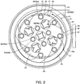
- These discharging cylindrical parts 64 include a plurality of outer discharging cylindrical parts 64a corresponding to the first discharging cylindrical parts located on one relatively-large circle so as to be separated from each other, and a plurality of inner discharging cylindrical parts 64b corresponding to the second discharging cylindrical parts located on one relatively-small circle so as to be separated from each other, and the outer discharging cylindrical parts 64a and the inner discharging cylindrical parts 64b are arranged concentrically and symmetrically.
- the outer discharging cylindrical parts 64a are arranged outside the opening parts 85 (the outer opening parts 85b) and on the back side of the partitions 78 of the shroud part 66, that is, in close contact with the inside of the shroud part 66.
- outer discharging cylindrical parts 64a are arranged, for example, on every other partition 78 and also on both sides of each of the outer opening parts 85b (two for one outer opening part 85b).
- the inner discharging cylindrical parts 64b are arranged around the central axis of the shroud part 66 respectively between the adjacent outer opening parts 85b, 85b, and also outside the center opening part 85a.
- these discharging cylindrical parts 64 are arranged so as to surround each of the opening parts 85.
- the adjacent outer discharging cylindrical parts 64a , 64a and the adjacent inner discharging cylindrical parts 64b, 64b are arranged so as to surround one of the outer opening parts 85b
- the inner discharging cylindrical parts 64b are arranged so as to surround the center opening part 85a ( Fig. 2 ).
- the first centrifuge separator 47 swirls dust-including air in the swirling air path 76 arranged around the shroud part 66 along the inner face of the casing 45 to centrifuge dust and dirt.
- Each of the second centrifuge separators 48 respectively communicating in parallel with the first centrifuge separator 47 introduces dust-including air having passed through the first centrifuge separator 47 from the introduction parts 62 into the cone parts 63, swirls dust-including air along the inner faces of the cone parts 63 to centrifuge smaller dust and dirt (fine dust) than the dust and dirt (coarse dust) centrifuged by the first centrifuge separator 47, then stores them in the second storage part 71, and also discharges the air from which coarse dust has been separated and which is substantially free from dust and dirt, from the discharging cylindrical parts 64 to the exhaust air path part 69 (the exhaust part 55 (the exhaust port 55a)), that is, outside the dust-collecting device 27.
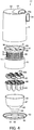
- the separator 46 is attached to the casing 45 to make them integrally assembled. Specifically, as for the separator 46, the first structure 73 is inserted to be held and locked in the casing 45 with the lower end side thereof opened by the lid 53, and further the upper end side of the second structure 74 holding at the upper end side thereof the connecting plate 96 connecting the cone parts 63 respectively having each of the introduction parts 62 is inserted to be held and locked in the first structure 73. This allows the separator 46 to be held coaxially in the casing 45 in a state where each of the air suction openings 62a of each of the introduction parts 62 is airtightly connected to each of the discharging cylindrical parts 64.
- the lower end side of the casing 45 is closed, and further the lower end part (the connecting part 89) of the separator body portion 61 of the separator 46 is brought into close contact with the receiving part 58 of the lid 53.
- the space surrounded by the casing 45 and the separator body portion 61 is partitioned into the first storage part 70 and the second storage part 71.
- the assembled dust-collecting device 27 is attached to the main casing 26, and then the dust-collecting device 27 is locked to the main casing 26 by use of the attaching/detaching mechanism.
- the dust-collecting device 27 is attached to the main casing 26 in a state in which the dust-collecting device 27 is airtightly connected to the suction side of the electric blower 35 and the main body suction port 41. In a state where the dust-collecting device 27 is already attached to the main casing 26, the operation described above is not required.
- the pipe part 12 is connected to the main body suction port 41 of the vacuum cleaner body portion 13 (main casing 26). Specifically, the connecting pipe part 15 of the pipe part 12 is inserted in and connected to the main body suction port 41, and, if necessary, the extension pipe 18 and the floor brush 19 are connected to the tip side of the hand operating part 17 one by one. In this state, the setting buttons 22 of the hand operating part 17 are electrically connected to the control circuit part or the like included in the vacuum cleaner body portion 13 (main casing 26). When the pipe part 12 is already connected to the vacuum cleaner body portion 13, the operation described above is not required.
- the control circuit part After getting ready for power feeding to the electric blower 35, the control circuit part or the like, a user grips the gripping part 21 and operates a desired button of the setting buttons 22 to set an operation mode of the electric blower 35.
- the control circuit part controls input to the electric blower 35 in accordance with the set operation mode to start the electric blower 35 in the set operation mode.
- the negative pressure generated by the start of the electric blower 35 acts on the pipe part 12 via the air suction opening part, the exhaust part 55, the exhaust air path part 69, the second centrifuge separators 48, the straightening part 83, the first centrifuge separator 47, the introduction port 54, the communicating opening, and the main body suction port 41.
- a user uses the action generated by the negative pressure for sucking dust and dirt as well as air from the tip side of the floor brush 19, the extension pipe 18, or the hand operating part 17.
- the air including dust and dirt that is, dust-including air, is introduced from the pipe part 12 through the main body suction port 41 and the communicating opening to the introduction port 54, and then sucked from the introduction port 54 into the dust-collecting device 27, that is, into the first centrifuge separator 47.
- first centrifuge separator 47 dust-including air swirls in the swirling air path 76 along the inner circumferential face 45a of the casing 45. This especially centrifuges coarse dust in dust-including air, and the centrifuged coarse dust falls along the inner circumferential face 45a of the casing 45, and then is stored in the first storage part 70 having a doughnut shape below the separator part 67.
- Dust-including air swirling in the swirling air path 76 is filtered by the separation filters 79. Dust-including air after passing through the separation filters 79 is straightened by the straightening part 83 while being guided respectively to each of the opening parts 85 by the discharging cylindrical parts 64, then passes through from each of the opening parts 85 to the inside of the separator part 67, and is further equally distributed respectively from the air suction openings 62a of each of the introduction parts 62 into the second centrifuge separators 48 (into the cone parts 63).
- the air substantially free from dust and dirt after centrifuging of fine dust is discharged from the air exhaust openings 62b of the introduction parts 62 of each of the second centrifuge separators 48 respectively via each of the discharging cylindrical parts 64, and collectively to the exhaust air path part 69, and then discharged outside the dust-collecting device 27 via the exhaust air path part 69 from the exhaust part 55 (the exhaust port 55a).
- the air is sucked from the air suction opening part through to the electric blower 35 and cools the inside of the electric blower 35 when passing through, and then is discharged as exhaust air outside the main casing 26 via the exhaust hole from the electric blower 35.
- a user After finishing the cleaning, a user operates a prescribed button of the setting buttons 22 to make the control circuit part decrease the input to the electric blower 35 to stop the electric blower 35.
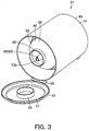
- the dust-collecting device 27 When a certain amount of dust and dirt is stored in the dust-collecting device 27, the dust-collecting device 27 is removed from the main casing 26 and brought to a location for disposal such as a bin. Then operation on an operation part of the locking mechanism is performed to make the lid 53 rotate downward around the hinge part 59 by self-weight. This opens the lower part of the casing 45 to separate the lid 53 (the receiving part 58) and the lower end part (the collective wall part 68 (the connecting part 89)) of the separator body portion 61 from each other. Thus, the coarse dust and the fine dust stored above the lid 53 are disposed of collectively. Upon the disposal, as the coarse dust surrounds the fine dust, disposing of the fine dust surrounded by the coarse dust suppresses rising of the fine dust, thereby allowing sanitary disposing of the dust.
- the embodiment described above has the configuration with the first centrifuge separator 47 that centrifuges dust and dirt by swirling dust-including air around the shroud part 66 along the inner circumferential face 45a of the casing 45, and the plurality of second centrifuge separators 48 that respectively communicate in parallel with the first centrifuge separator 47 and centrifuge smaller dust and dirt compared to the dust and dirt to be centrifuged by the first centrifuge separator 47 by swirling along the inner faces of each of the cone parts 63 dust-including air having passed through the first centrifuge separator 47.
- the use of the first centrifuge separator 47 and plurality of the second centrifuge separators 48 allows efficient collection of dust and dirt.
- each of the second centrifuge separators 48 inside the separator part 67 located below the shroud part 66 of the first centrifuge separator 47 allows the use of the structural space of the first centrifuge separator 47, and each of the second centrifuge separators 48 likely generating large noise due to the high speed of swirling flow compared to that in the first centrifuge separator 47 can be contained in the outer shell of the first centrifuge separator 47, thereby suppressing noise.
- the separator body portion 61 partitions off, due to the close contact with the casing 45, the interior of the casing 45 into an outer part and an inner part, that is, the first storage part 70 that stores the dirt and dust (coarse dust) centrifuged by the first centrifuge separator 47, and the second storage part 71 that stores the dirt and dust (fine dust) centrifuged by the second centrifuge separators 48, the coarse dust stored in the first storage part 70 can surround the fine dust stored in the second storage part 71, thereby suppressing rising of the fine dust or the like and resulting in sanitary disposing of dust.
- the cone parts 63 included in the second centrifuge separators 48 are arranged inside the separator part 67 and also inside the collective wall part 68, the noise generated at the cone parts 63 is insulated double, thereby suppressing the noise more effectively.
- the outer opening parts 85b are located close to the inner circumference of the shroud part 66.
- dust-including air having passed through the ventilation openings 77 easily, early and also effectively flows into the second centrifuge separators 48 via the opening parts 85 (the outer opening parts 85b).
- dust-including air sucked into the dust-collecting device 27 is sucked toward the second centrifuge separators 48 early without drifting inside the dust-collecting device 27, especially the fine dust included in dust-including air is hardly stuck on respective parts.
- the shroud part 66 is located at substantially the same height as the introduction port 54, dust-including air introduced from the introduction port 54 to the first centrifuge separator 47 (the swirling air path 76) as is flows into the ventilation openings 77, and then is introduced via the opening parts 85 (the straightening part 83) respectively to each of the second centrifuge separators 48 (the cone parts 63).
- dust-including air smoothly flows respectively to each of the second centrifuge separators 48 (the cone parts 63) without moving up and down repeatedly, resulting in providing higher efficiency.
- the outer discharging cylindrical parts 64a are the guides to guide a part of dust-including air to the opening parts 85 (the outer opening parts 85b).
- dust-including air having passed through the ventilation openings 77 can efficiently flow to the opening parts 85 (the outer opening parts 85b).
- each of the opening parts 85 is surrounded by the discharging cylindrical parts 64, each of the opening parts 85 is located at a place in which dust-including air having passed through the ventilation openings 77 is kept away from these discharging cylindrical parts 64, and thus the discharging cylindrical parts 64 as a whole can guide dust-including air to the opening parts 85.
- the outer discharging cylindrical parts 64a are located on the back side of the partitions 78, the outer discharging cylindrical parts 64a hardly disturb the flow of dust-including air passing through the ventilation openings 77, thus suppressing the noise generated by turbulence or the like.
- the dust-collecting device 27 has the configuration in which dust and dirt is disposed of from the lower part of the dust-collecting device 27 by opening the bottom portion of the casing 45 by use of the lid 53.
- a dust-collecting device 27 may have another configuration in which a casing 45 has a bottomed cylindrical shape and dust and dirt is disposed of from the upper end side of the casing 45 after removing a separator 46 (a separator body portion 61) from the casing 45.
- cleaners not limited to a canister type cleaner
- a vacuum cleaner 11 can also be applied as a vacuum cleaner 11, for example, a so-called upright vacuum cleaner that has a main casing 26 having an up-and-down long shape with a floor brush 19 connected to the lower end part of the main casing 26, a so-called stick type vacuum cleaner that has a main casing 26 to which an extension pipe 18 and a floor brush 19 are connected directly, or the like.
Landscapes
- Engineering & Computer Science (AREA)
- Mechanical Engineering (AREA)
- Filters For Electric Vacuum Cleaners (AREA)
- Electric Suction Cleaners (AREA)
Abstract
Description
- Embodiments described herein relate generally to a vacuum cleaner equipped with a dust-collecting device having a first centrifuge separator that centrifuges dust and dirt, and a plurality of second centrifuge separators that centrifuge smaller dust and dirt compared to that centrifuged by the first centrifuge separator.
- Some of conventional dust-collecting devices (dust-collecting cups) for use in a vacuum cleaner respectively include a first centrifuge separator that centrifuges coarse dust corresponding to relatively large dust and dirt, and a plurality of second centrifuge separators that communicate with the downstream side of the first centrifuge separator and centrifuge fine dust (ultrafine dust) corresponding to relatively small dust and dirt. By applying the configuration with these centrifuge separators for centrifuging dust and dirt different from each other, maintenance frequency and labor required of users have been reduced.
- However, the second centrifuge separators become noise sources that generate relatively large fluid noise because each of the second centrifuge separators has a smaller diameter compared to the first centrifuge separator and thus the fluid speed is higher. Accordingly, there is a need to reduce the noise generated by these second centrifuge separators.
- PTL 1: Japanese Laid-open Patent Publication No.
2010-201167 - An object of the present invention is to provide a vacuum cleaner capable of suppressing noise and sanitary disposing of dust and dirt, while efficiently collecting dust and dirt by use of a first centrifuge separator and a plurality of second centrifuge separators.
- A vacuum cleaner in an embodiment includes a vacuum cleaner body portion including an electric blower, and a dust-collecting device that separates and collects dust and dirt from dust-including air sucked by drive of the electric blower. The dust-collecting device includes a first centrifuge separator, a plurality of second centrifuge separators, a first dust-collecting unit and a second dust-collecting unit. The first centrifuge separator includes a casing and a separator body portion. The separator body portion includes a first cylindrical part having a substantially cylindrical shape with a ventilation opening on the circumferential face thereof. The separator body portion also includes a separator part having a cylindrical shape located below the first cylindrical part. In addition, the separator body portion is accommodated in the casing so that a lower end side of the separator body portion is brought in close contact with the casing. The first centrifuge separator centrifuges dust and dirt by swirling dust-including air around the first cylindrical part along an inner face of the casing. Each of the plurality of second centrifuge separators includes a second cylindrical part. The second cylindrical part is formed to have a substantially cylindrical shape with a smaller diameter compared to the first cylindrical part and communicates respectively in parallel with the first centrifuge separator. Each of the plurality of second centrifuge separators centrifuges smaller dust and dirt compared to that centrifuged by the first centrifuge separator by swirling dust-including air having passed through the first centrifuge separator along an inner face of the second cylindrical part. The first dust-collecting unit stores the dust and dirt centrifuged by the first centrifuge separator. The second dust-collecting unit stores the dust and dirt centrifuged by the plurality of second centrifuge separators. The plurality of second centrifuge separators are respectively located inside the separator part. The separator body portion partitions off, due to close contact with the casing, the interior of the casing into an outer part and an inner part, that is, the first dust-collecting unit and the second dust-collecting unit.
-
- [
Fig. 1 ]
Fig. 1 is a perspective sectional view showing a dust-collecting device of a vacuum cleaner in one embodiment; - [
Fig. 2 ]
Fig. 2 is a cross sectional view showing the above dust-collecting device; - [
Fig. 3 ]
Fig. 3 is a perspective view showing an operating state of the above dust-collecting device when dust and dirt in the dust-collecting device are disposed of; - [
Fig. 4 ]
Fig. 4 is a disassembled perspective view showing the above dust-collecting device; and - [
Fig. 5 ]
Fig. 5 is a perspective view showing the above vacuum cleaner. - Hereinbelow, one embodiment will be described in terms of its constitution with reference to
Figs. 1 to 5 . - In
Fig. 5 ,reference sign 11 denotes a so-called canister type vacuum cleaner. Thisvacuum cleaner 11 includes apipe part 12 corresponding to a suction air path element (air path forming body), and a vacuumcleaner body portion 13 to which thepipe part 12 is detachably connected. - The
pipe part 12 includes a connectingpipe part 15 to be connected to the vacuumcleaner body portion 13, aflexible hose body 16 communicating with the tip side of the connectingpipe part 15, ahand operating part 17 arranged on the tip side of thehose body 16, anextension pipe 18 to be detachably connected to the tip side of thehand operating part 17, and afloor brush 19 corresponding to a suction port to be detachably connected to the tip side of theextension pipe 18 or the like. - The hand operating
part 17 is provided with a looped grippingpart 21 projecting toward thehose body 16 side, and a plurality of settingbuttons 22 for operation on the grippingpart 21. - As shown in
Figs. 1 to 5 , the vacuumcleaner body portion 13 includes amain casing 26 which has large-diametertraveling wheels 23 on the both sides thereof, a swing wheel (not shown in figures) and other elements on the lower part thereof, and also includes a detachable dust-collectingdevice 27 corresponding to a dust-collecting cup externally on the upper front part of themain casing 26. The vacuumcleaner body portion 13 is configured to be capable of traveling (moving) on a floor surface to be cleaned at least along a back-and-forth direction by use of thetraveling wheels 23 and the swing wheel. Hereinafter, the back-and-forth direction is based on the traveling (moving) direction of the vacuum cleaner body portion 13 (main casing 26) . - The
main casing 26, for example, made of synthetic resin, integrally includes abody portion 31 disposed behind the dust-collectingdevice 27, and a projectingreceiver 32 corresponding to a dust-collecting device support part that projects in the lower front side of thebody portion 31 and supports the lower part of the dust-collectingdevice 27. - Respectively on the both sides of the
body portion 31, thetraveling wheels 23 are pivotally and rotatably supported. Thebody portion 31 also accommodates anelectric blower 35, a control circuit part (not shown in figures) corresponding to control means that controls the operation of theelectric blower 35, and a power source part corresponding to a power source for theelectric blower 35, the control circuit part or the like. As the power source part, a cord reel device with wound power cord for connection to an external power source such as a commercial AC power source, or a battery such as a secondary battery is used. - A communicating opening (not shown in figures) is formed at the front lower part of the
body portion 31, which is airtightly connected to the upstream side of the dust-collectingdevice 27 attached to themain casing 26. Further, an air suction opening part (not shown in figures) is formed on the upper part of thebody portion 31, which communicates between the downstream side of the dust-collectingdevice 27 attached to themain casing 26 and the suction side of theelectric blower 35. An exhaust hole (not shown in figures) is formed on the rear part of thebody portion 31, which discharges exhaust from theelectric blower 35. - A main
body suction port 41 is formed on the front face of the projectingreceiver 32, to which the connectingpipe part 15 of thepipe part 12 is connected to suck dust-including air into the dust-collectingdevice 27. The mainbody suction port 41 communicates with the communicating opening. Thus, the mainbody suction port 41 can communicate with the upstream side of the dust-collectingdevice 27 attached to themain casing 26. - The operation of the
electric blower 35 is controlled by the control circuit part in accordance with operation on thesetting buttons 22. In the embodiment, theelectric blower 35 is arranged, for example, so that the suction side of theelectric blower 35 faces upward. - The control circuit part is electrically connected to the
setting buttons 22, and is configured to set the operation of theelectric blower 35 to the operation mode (for example, strong mode, middle mode, weak mode, automatic mode, stop mode, etc.) set by the operation on thesetting buttons 22. - The dust-collecting
device 27 includes acasing 45 that is a container corresponding to a first body portion, and aseparator 46 that is a dust-and-dirt separator corresponding to a second body portion to be accommodated inside thecasing 45. The dust-collecting device 27 is also constituted with afirst centrifuge separator 47 and a plurality ofsecond centrifuge separators 48. Thefirst centrifuge separator 47 mainly centrifuges relatively large dust and dirt, that is, coarse dust, which is a part of the dust and dirt in the dust-including air sucked by drive of theelectric blower 35. Thesecond centrifuge separators 48 respectively centrifuge relatively small dust and dirt, that is, fine dust (ultrafine dust), which is the remaining dust and dirt not having been centrifuged by thefirst centrifuge separator 47. The dust-collectingdevice 27 is detachably locked to themain casing 26 by an attaching/detaching mechanism (not shown in figures). The back-and-forth direction and the left-and-right direction in terms of the dust-collectingdevice 27 is based on a state in which the dust-collectingdevice 27 is attached to themain casing 26, and the up-and-down direction in terms of the dust-collectingdevice 27 is based on a state in which the dust-collectingdevice 27 is detached from themain casing 26 and placed on a horizontal plane, that is, based on the dust-collecting device 27 (the state shown inFig. 1 ). In the embodiment, the dust-collectingdevice 27 is attached to themain casing 26 so that the upper end side, corresponding to one end side, of the dust-collectingdevice 27 is inclined backward. Therefore, the up-and-down direction described hereafter when the dust-collectingdevice 27 is attached to themain casing 26 may not correspond to the vertical up-and-down direction. - The
casing 45 corresponds to the outer enclosure of the dust-collectingdevice 27, having a hollow and substantially cylindrical shape. Thecasing 45, in the embodiment, includes acasing body 51 that is a cylindrical container body, acover part 52 that is a ceiling part attached on the top end part corresponding to one end part of thecasing body 51, and alid 53 that is a bottom portion that opens and closes a lower end part corresponding to the other end part of thecasing body 51. Thecasing 45 also has on one side of the rear thereof, for example, on a location shifted to the right side thereof, anintroduction port 54 for sucking dust-including air. Further, the rear part of thecasing 45 is provided at the upper part thereof with anexhaust part 55 through which the air after separating of dust and dirt is discharged. - The
casing body 51 is made of a member, for example, translucent (transparent) synthetic resin. Theintroduction port 54 is arranged on thecasing body 51. - The
cover part 52 having a substantially circular plate shape seals up the upper end part of thecasing body 51. Theexhaust part 55 is arranged on thecover part 52. Thecover part 52 and thecasing body 51 may be formed integrally or separately. - The
lid 53 includes alid body 57 having a substantially circular disk shape, a receivingpart 58 having a cylindrical shape arranged concentrically with thelid body 57, and ahinge part 59 with which thelid 53 is pivotally and rotatably supported to thecasing body 51. Thelid 53 also includes a seal member and a locking mechanism (not shown in figures) . The seal member is brought into airtightly press-contact with the lower end part of thecasing body 51, and the locking mechanism with which thelid 53 is locked to thecasing body 51. - The receiving
part 58 projecting from the upper side of the central part of thelid body 57 supports theseparator 46 from below when thelid 53 is closed. - The
hinge part 59 arranged on one side part of thelid body 57 or the like connects between thelid 53 and thecasing body 51. - The seal member is arranged along the outer circumferential part of the
lid body 57 or the like. - The locking mechanism is arranged, for example, opposite side to and in the other side part of the
hinge part 59 on thelid body 57. The locking mechanism can release the locking of thelid 53 to thecasing body 51 in accordance with operation on an operation part (not shown in figures). - The
introduction port 54 is arranged in a location so as to face thebody portion 31 with the dust-collectingdevice 27 being attached to themain casing 26. Theintroduction port 54 extending backward and substantially horizontally is airtightly connected to the communicating opening with the dust-collectingdevice 27 being attached to themain casing 26. Thus, theintroduction port 54 is airtightly connected to the main body suction port 41 (via the communicating opening). - The
exhaust part 55 extends cylindrically backward from the substantially central part of thecover part 52. The tip side of theexhaust part 55 forms anexhaust port 55a that faces thebody portion 31 with the dust-collectingdevice 27 being attached to themain casing 26. - The
separator 46 includes aseparator body portion 61, a plurality ofintroduction parts 62 that are accommodated in theseparator body portion 61, a plurality ofcone parts 63 corresponding to second cylindrical parts, and a plurality of dischargingcylindrical parts 64 corresponding to discharging parts. Theseparator 46 is detachably fixed to thecasing body 51 or thecover part 52 of thecasing 45. - The
separator body portion 61, along with thecasing 45, constituting thefirst centrifuge separator 47, has ashroud part 66 corresponding to a first cylindrical part, aseparator part 67, acollective wall part 68 corresponding to a partition wall part, and an exhaustair path part 69. Theseparator body portion 61 is arranged inside thecasing 45 along the central axis of thecasing 45 so that the lower end side (lower end part) of theseparator body portion 61 is supported in close contact with the casing 45 (the lid 53 (the receiving part 58)). Thus, theseparator body portion 61 partitions off, due to the close contact with thecasing 45, the interior of thecasing 45 into an outer part and an inner part, that is, afirst storage part 70 and asecond storage part 71. Thefirst storage part 70 is a first dust-collecting unit that stores the dust and dirt (coarse dust) centrifuged by thefirst centrifuge separator 47, and thesecond storage part 71 is a second dust-collecting unit that stores the dust and dirt (fine dust) centrifuged respectively by thesecond centrifuge separators 48. Theseparator body portion 61 is divided into afirst structure 73 integrally including theshroud part 66, theseparator part 67 and the exhaustair path part 69, and asecond structure 74 including thecollective wall part 68. - The
shroud part 66 forms a swirlingair path 76 to swirl dust-including air as the rotation center of thefirst centrifuge separator 47 between (around) the outer circumference of theshroud part 66 and an innercircumferential face 45a of thecasing 45. Theshroud part 66 having a cylindrical shape with the axis thereof set along up-and-down direction is located in the center of and coaxially with thecasing 45. Further, theshroud part 66 is arranged at substantially the same height as theintroduction port 54. Theshroud part 66 also includes a plurality ofventilation openings 77 on the circumferential face thereof, and apartition 78 is arranged between theadjacent ventilation openings ventilation openings 77 is covered by aseparation filter 79. - The
ventilation openings 77 penetrate the circumferential face of theshroud part 66 so as to communicate between the outer circumferential side (the swirling air path 76) and the inner circumferential side of theshroud part 66. Theventilation openings 77 respectively having, for example, a square shape long in the up-and-down direction are opened and substantially equally separated from each other in the circumferential direction of theshroud part 66. Thus, thepartitions 78 respectively having a shape long in the up-and-down direction are located in the circumferential direction of theshroud part 66 at substantially equal intervals, so as to form a grid shape (lattice shape). - The
separation filter 79, for example, a mesh filter, filters and separates dust and dirt in dust-including air passing through theventilation openings 77. - The
separator part 67 partitions off the interior of thecasing 45 into an upper part and a lower part, that is, the swirlingair path 76 and thefirst storage part 70. Theseparator part 67 is located adjacent to the lower end part of theshroud part 66. That is, theseparator part 67 is located below theshroud part 66. Theseparator part 67 is formed in a cylindrical shape with a lid with the axis thereof set along the up-and-down direction, having a larger diameter compared to theshroud part 66, and is arranged coaxially with theshroud part 66. That is, theseparator part 67 includes atop plate part 81 having a circular plate shape and acircumferential plate part 82 having a substantially cylindrical shape that projects downward in the opposite direction to theshroud part 66 from the outer circumferential part of thetop plate part 81. Theseparator part 67 also includes a straighteningpart 83 that straightens dust-including air passing from the swirlingair path 76 respectively to thesecond centrifuge separators 48 via theventilation openings 77. - The
top plate part 81 is located so as to cover the lower end part of theshroud part 66. Thetop plate part 81 has a larger diameter compared to theshroud part 66, and the outer circumferential part of thetop plate part 81 projects radially and outwardly with respect to theshroud part 66. Thetop plate part 81 has, for example, a plurality of openingparts 85 in an area corresponding to the inside area of theshroud part 66. The openingparts 85 introduce dust-including air having passed from the swirlingair path 76 to theshroud part 66 via the ventilation openings 77 (separation filters 79), to the inside of the separator part 67 (each of the second centrifuge separators 48 (each of the cone parts 63)). The openingparts 85, for example, respectively formed in a circular shape, are arranged symmetrically on thetop plate part 81. The openingparts 85 include acenter opening part 85a arranged at the center of thetop plate part 81, that is, at the central axis of theshroud part 66, and a plurality of outer openingparts 85b arranged at intervals on the same circle closer to the outer circumference of thecenter opening part 85a, that is, near the inner circumference of theshroud part 66. - The straightening
part 83 is constituted with a part of thetop plate part 81 in the inner circumferential side of theshroud part 66, and the plurality of openingparts 85. That is, the straighteningpart 83 communicates between theventilation openings 77 and each of thesecond centrifuge separators 48. - The
collective wall part 68 integrally includes anupper wall part 87 having a substantially cylindrical shape corresponding to a partition wall part body, adiameter reducing part 88 corresponding to a dust guide part that is continued to the lower end part of theupper wall part 87 and reduced in diameter from its upper end side to its lower end side, and a connectingpart 89 having a cylindrical shape corresponding to a supported part continued to the lower end part of thediameter reducing part 88. As a whole, thecollective wall part 68 is formed substantially in a cylindrical shape with the diameter thereof reduced from the upper end part side to the lower end part side. The upper end part side (the upper end part side of the upper wall part 87) of thecollective wall part 68 is located inside theseparator part 67, while the lower end part side (the lower end part side of theupper wall part 87, thediameter reducing part 88, and the connecting part 89) projects downward from theseparator part 67 and located in thecasing 45. The inner part of thecollective wall part 68 communicates with thesecond storage part 71. - The
upper wall part 87 is formed with the diameter gradually reduced from the upper end part side to the lower end part side. The lower end part of theupper wall part 87 has, for example, a larger diameter compared to theshroud part 66. - The
diameter reducing part 88 that guides the dust and dirt (fine dust) centrifuged respectively by thesecond centrifuge separators 48 is inclined toward thesecond storage part 71. - The connecting
part 89 is the part to make the separator body portion 61 (the separator 46) in close contact with the bottom portion (the lid 53) of thecasing 45, and to support theseparator body portion 61. The connectingpart 89 is formed with a diameter having substantially the same size as the receivingpart 58 of thelid 53 so as to be in close contact with the receivingpart 58 with thelid 53 closing the lower end part of thecasing 45. - The exhaust
air path part 69 communicates between all of thesecond centrifuge separators 48 and the exhaust part 55 (theexhaust port 55a), and flows the air substantially free from dust and dirt having passed through thesecond centrifuge separators 48, through to the exhaust part 55 (theexhaust port 55a). The exhaustair path part 69 is adjacent to the upper end part of theshroud part 66, in the opposite side to theseparator part 67. That is, the exhaustair path part 69 is located above theshroud part 66. The exhaustair path part 69 having a bottomed cylindrical shape with a larger diameter compared to theshroud part 66 and with the axis direction thereof set along the up-and-down direction is arranged coaxially with theshroud part 66. That is, the exhaustair path part 69 includes an air pathpartition wall part 91 having a circular plate shape and acircumferential wall part 92 that projects upward from the outer circumferential part of the air pathpartition wall part 91 in the opposite side to theshroud part 66 so as to be in close contact with the inside of the casing 45 (the upper end side of thecasing body 51 or the lower part of the cover part 52) . - The air path
partition wall part 91 is located so as to cover the upper end part of theshroud part 66. The air pathpartition wall part 91 has, for example, a plurality of communicatingopenings 94 in an area corresponding to the inside area of theshroud part 66. These communicatingopenings 94 that introduce the air having passed through each of thesecond centrifuge separators 48 into the exhaustair path part 69 respectively communicate with the upper end parts (the downstream end parts) of each of the dischargingcylindrical parts 64. - The
circumferential wall part 92 is formed in a cylindrical shape with the diameter thereof gradually increased from the lower end side to the upper end side thereof. - The
first storage part 70 is the space partitioned by thecasing body 51 and thelid 53, and the outer side of thecollective wall part 68 of theseparator body portion 61, due to the close contact between the connectingpart 89 of thecollective wall part 68 of theseparator body portion 61 and the receivingpart 58 of thelid 53. That is, thefirst storage part 70 is the space in the outer circumferential side of thecollective wall part 68 inside thecasing 45. - The
second storage part 71 is the space partitioned by the lid 53 (the receiving part 58) and the inner side of thecollective wall part 68 of theseparator body portion 61, due to the close contact between the connectingpart 89 of thecollective wall part 68 of theseparator body portion 61 and the receivingpart 58 of thelid 53. Further, thesecond storage part 71 is surrounded by the receivingpart 58 of thelid 53 in the embodiment. - Therefore, the
first storage part 70 is arranged in a doughnut shape (in an annular shape) around thesecond storage part 71. That is, thefirst storage part 70 and thesecond storage part 71 are positioned concentrically. - As for the
first structure 73, the upper end side (the exhaust air path part 69 (the circumferential wall part 92)) is fixed to the casing 45 (thecasing body 51 or the cover part 52), while the lower end side (the side of the separator part 67) is left free. As thesecond structure 74, the upper end side (the collective wall part 68 (the upper wall part 87)) is inserted into theseparator part 67 of thefirst structure 73 so as to be detachably locked and held, while the lower end side (the lower end side of the collective wall part 68 (the connecting part 89)) is left free. - The
introduction parts 62 are respectively disposed on the upper end parts of each of thecone parts 63 so as to introduce dust-including air having passed through thefirst centrifuge separator 47 into each of thecone parts 63 respectively and spirally along the tangential directions of the inner circumferential faces of thecone parts 63, and further respectively communicate between each of the cone parts 63 (each of the second centrifuge separators 48) and the dischargingcylindrical parts 64. Theintroduction parts 62 are also located below the separator part 67 (the straightening part 83), andair suction openings 62a (the upstream side) respectively located around theintroduction parts 62 communicate with theventilation openings 77 via the openingparts 85. Thus, the suction sides of theseintroduction parts 62 communicate with the swirling air path 76 (via the straightening part 83 (the opening parts 85) and the ventilation openings 77). The directions of the openings of theair suction openings 62a of each of theintroduction parts 62 are set respectively differently by a specified angle, so that the air having passed through the opening parts 85 (the straightening part 83) into theseparator part 67 is distributed substantially equally to each of thecone parts 63. Anair exhaust opening 62b located at the center of each of the introduction parts 62 (the downstream side) is connected to each of the dischargingcylindrical parts 64. Thus, the exhaust sides of theintroduction parts 62 communicate with the exhaust air path part 69 (via each of the discharging cylindrical parts 64). - Each of the
cone parts 63 is paired with each of theintroduction parts 62 so as to configure each of thesecond centrifuge separators 48, and communicates in parallel with thefirst centrifuge separator 47. Thesecone parts 63 respectively having a smaller diameter compared to theshroud part 66 are located with these axial directions set along a vertical up-and-down direction, that is, in substantially parallel to the central axis of the dust-collectingdevice 27, and are respectively formed in a substantially cylindrical shape with the diameter gradually reduced from the upper end side through which dust-including air flows to the lower end side. Thus, thesecone parts 63 can centrifuge fine dust because in thesecone parts 63 the swirling diameter of dust-including air is smaller than the swirling diameter in the swirlingair path 76 of thefirst centrifuge separator 47 and the swirling speed is higher than the swirling speed in the swirlingair path 76 of thefirst centrifuge separator 47. Further, thesecone parts 63 are integrally connected by, for example, a connectingplate 96 corresponding to a connecting part. Thesecone parts 63 are supported by the connectingplate 96 at the upper end part of the second structure 74 (the collective wall part 68 (the upper wall part 87)), so as to be accommodated inside thecollective wall part 68. Thus, thesecone parts 63 are located inside theseparator part 67. The lower end parts of thesecone parts 63 are located at a position separated from and above thediameter reducing part 88 so as to face thediameter reducing part 88, and communicate with thesecond storage part 71. Thus, the lower end parts of thesecone parts 63 are formed as dischargingopening parts 63a, and discharge the fine dust centrifuged by thesecond centrifuge separators 48 to thesecond storage part 71. - Each of the discharging
cylindrical parts 64 having an elongated cylindrical shape communicates between each of the second centrifuge separators 48 (each of the cone parts 63) and the exhaustair path part 69. That is, each of the dischargingcylindrical parts 64 is arranged so as to correspond to each of the second centrifuge separators 48 (each of the cone parts 63), and the lower end part (the upstream side) is airtightly connected to each of theair exhaust openings 62b of each of theintroduction parts 62, while the upper end part (the downstream side) is airtightly connected to each of the communicatingopenings 94. These dischargingcylindrical parts 64, with the axial directions set along a vertical up-and-down direction, that is, substantially in parallel to the central axis of the dust-collectingdevice 27, penetrate the top plate part 81 (the straightening part 83) of theseparator part 67, and are located in the inside part of theshroud part 66. That is, these dischargingcylindrical parts 64 are located in dust-including air to be branched from the ventilation openings 77 (via the straightening part 83) to each of the second centrifuge separators 48 (each of the cone parts 63) . These dischargingcylindrical parts 64 include a plurality of outer dischargingcylindrical parts 64a corresponding to the first discharging cylindrical parts located on one relatively-large circle so as to be separated from each other, and a plurality of inner dischargingcylindrical parts 64b corresponding to the second discharging cylindrical parts located on one relatively-small circle so as to be separated from each other, and the outer dischargingcylindrical parts 64a and the inner dischargingcylindrical parts 64b are arranged concentrically and symmetrically. The outer dischargingcylindrical parts 64a are arranged outside the opening parts 85 (the outer openingparts 85b) and on the back side of thepartitions 78 of theshroud part 66, that is, in close contact with the inside of theshroud part 66. These outer dischargingcylindrical parts 64a are arranged, for example, on everyother partition 78 and also on both sides of each of the outer openingparts 85b (two for oneouter opening part 85b). The inner dischargingcylindrical parts 64b are arranged around the central axis of theshroud part 66 respectively between the adjacent outer openingparts center opening part 85a. Thus, these dischargingcylindrical parts 64 are arranged so as to surround each of the openingparts 85. Specifically, the adjacent outer dischargingcylindrical parts cylindrical parts parts 85b, and the inner dischargingcylindrical parts 64b are arranged so as to surround thecenter opening part 85a (Fig. 2 ). - The
first centrifuge separator 47 swirls dust-including air in the swirlingair path 76 arranged around theshroud part 66 along the inner face of thecasing 45 to centrifuge dust and dirt. - Each of the
second centrifuge separators 48 respectively communicating in parallel with thefirst centrifuge separator 47 introduces dust-including air having passed through thefirst centrifuge separator 47 from theintroduction parts 62 into thecone parts 63, swirls dust-including air along the inner faces of thecone parts 63 to centrifuge smaller dust and dirt (fine dust) than the dust and dirt (coarse dust) centrifuged by thefirst centrifuge separator 47, then stores them in thesecond storage part 71, and also discharges the air from which coarse dust has been separated and which is substantially free from dust and dirt, from the dischargingcylindrical parts 64 to the exhaust air path part 69 (the exhaust part 55 (theexhaust port 55a)), that is, outside the dust-collectingdevice 27. - Hereafter, the cleaning motion in accordance with the embodiment described above will be described.
- For start of cleaning, firstly, the
separator 46 is attached to thecasing 45 to make them integrally assembled. Specifically, as for theseparator 46, thefirst structure 73 is inserted to be held and locked in thecasing 45 with the lower end side thereof opened by thelid 53, and further the upper end side of thesecond structure 74 holding at the upper end side thereof the connectingplate 96 connecting thecone parts 63 respectively having each of theintroduction parts 62 is inserted to be held and locked in thefirst structure 73. This allows theseparator 46 to be held coaxially in thecasing 45 in a state where each of theair suction openings 62a of each of theintroduction parts 62 is airtightly connected to each of the dischargingcylindrical parts 64. With thelid 53 closed, the lower end side of thecasing 45 is closed, and further the lower end part (the connecting part 89) of theseparator body portion 61 of theseparator 46 is brought into close contact with the receivingpart 58 of thelid 53. Thus, the space surrounded by thecasing 45 and theseparator body portion 61 is partitioned into thefirst storage part 70 and thesecond storage part 71. - Then, the assembled dust-collecting
device 27 is attached to themain casing 26, and then the dust-collectingdevice 27 is locked to themain casing 26 by use of the attaching/detaching mechanism. This makes theintroduction port 54 and theexhaust part 55 of the dust-collectingdevice 27 be airtightly connected respectively to the communicating opening and the air suction opening part of themain casing 26. Thus, the dust-collectingdevice 27 is attached to themain casing 26 in a state in which the dust-collectingdevice 27 is airtightly connected to the suction side of theelectric blower 35 and the mainbody suction port 41. In a state where the dust-collectingdevice 27 is already attached to themain casing 26, the operation described above is not required. - In this state, the
pipe part 12 is connected to the mainbody suction port 41 of the vacuum cleaner body portion 13 (main casing 26). Specifically, the connectingpipe part 15 of thepipe part 12 is inserted in and connected to the mainbody suction port 41, and, if necessary, theextension pipe 18 and thefloor brush 19 are connected to the tip side of thehand operating part 17 one by one. In this state, the settingbuttons 22 of thehand operating part 17 are electrically connected to the control circuit part or the like included in the vacuum cleaner body portion 13 (main casing 26). When thepipe part 12 is already connected to the vacuumcleaner body portion 13, the operation described above is not required. - After getting ready for power feeding to the
electric blower 35, the control circuit part or the like, a user grips thegripping part 21 and operates a desired button of the settingbuttons 22 to set an operation mode of theelectric blower 35. The control circuit part controls input to theelectric blower 35 in accordance with the set operation mode to start theelectric blower 35 in the set operation mode. - The negative pressure generated by the start of the
electric blower 35 acts on thepipe part 12 via the air suction opening part, theexhaust part 55, the exhaustair path part 69, thesecond centrifuge separators 48, the straighteningpart 83, thefirst centrifuge separator 47, theintroduction port 54, the communicating opening, and the mainbody suction port 41. - A user uses the action generated by the negative pressure for sucking dust and dirt as well as air from the tip side of the
floor brush 19, theextension pipe 18, or thehand operating part 17. - The air including dust and dirt, that is, dust-including air, is introduced from the
pipe part 12 through the mainbody suction port 41 and the communicating opening to theintroduction port 54, and then sucked from theintroduction port 54 into the dust-collectingdevice 27, that is, into thefirst centrifuge separator 47. - In the
first centrifuge separator 47, dust-including air swirls in the swirlingair path 76 along the innercircumferential face 45a of thecasing 45. This especially centrifuges coarse dust in dust-including air, and the centrifuged coarse dust falls along the innercircumferential face 45a of thecasing 45, and then is stored in thefirst storage part 70 having a doughnut shape below theseparator part 67. - When passing through the
ventilation openings 77 of theshroud part 66, dust-including air swirling in the swirlingair path 76 is filtered by the separation filters 79. Dust-including air after passing through the separation filters 79 is straightened by the straighteningpart 83 while being guided respectively to each of the openingparts 85 by the dischargingcylindrical parts 64, then passes through from each of the openingparts 85 to the inside of theseparator part 67, and is further equally distributed respectively from theair suction openings 62a of each of theintroduction parts 62 into the second centrifuge separators 48 (into the cone parts 63). - In these second centrifuge separators 48 (the cone parts 63), dust-including air is swirled along the inner circumferential faces (the inner circumferential faces of the cone parts 63) to centrifuge fine dust from dust-including air, and the centrifuged fine dust falls along the second centrifuge separators 48 (the inner circumferential faces of the cone parts 63) then from the discharging
opening parts 63a toward the lower part of thecone parts 63. The fine dust falls on thediameter reducing part 88 located below each of thecone parts 63 and then along the slope of thediameter reducing part 88 to thesecond storage part 71 for storage. - The air substantially free from dust and dirt after centrifuging of fine dust is discharged from the
air exhaust openings 62b of theintroduction parts 62 of each of thesecond centrifuge separators 48 respectively via each of the dischargingcylindrical parts 64, and collectively to the exhaustair path part 69, and then discharged outside the dust-collectingdevice 27 via the exhaustair path part 69 from the exhaust part 55 (theexhaust port 55a). - Then, the air is sucked from the air suction opening part through to the
electric blower 35 and cools the inside of theelectric blower 35 when passing through, and then is discharged as exhaust air outside themain casing 26 via the exhaust hole from theelectric blower 35. - After finishing the cleaning, a user operates a prescribed button of the setting
buttons 22 to make the control circuit part decrease the input to theelectric blower 35 to stop theelectric blower 35. - When a certain amount of dust and dirt is stored in the dust-collecting
device 27, the dust-collectingdevice 27 is removed from themain casing 26 and brought to a location for disposal such as a bin. Then operation on an operation part of the locking mechanism is performed to make thelid 53 rotate downward around thehinge part 59 by self-weight. This opens the lower part of thecasing 45 to separate the lid 53 (the receiving part 58) and the lower end part (the collective wall part 68 (the connecting part 89)) of theseparator body portion 61 from each other. Thus, the coarse dust and the fine dust stored above thelid 53 are disposed of collectively. Upon the disposal, as the coarse dust surrounds the fine dust, disposing of the fine dust surrounded by the coarse dust suppresses rising of the fine dust, thereby allowing sanitary disposing of the dust. - The embodiment described above has the configuration with the
first centrifuge separator 47 that centrifuges dust and dirt by swirling dust-including air around theshroud part 66 along the innercircumferential face 45a of thecasing 45, and the plurality ofsecond centrifuge separators 48 that respectively communicate in parallel with thefirst centrifuge separator 47 and centrifuge smaller dust and dirt compared to the dust and dirt to be centrifuged by thefirst centrifuge separator 47 by swirling along the inner faces of each of thecone parts 63 dust-including air having passed through thefirst centrifuge separator 47. Thus, the use of thefirst centrifuge separator 47 and plurality of thesecond centrifuge separators 48 allows efficient collection of dust and dirt. The arrangement of each of thesecond centrifuge separators 48 inside theseparator part 67 located below theshroud part 66 of thefirst centrifuge separator 47 allows the use of the structural space of thefirst centrifuge separator 47, and each of thesecond centrifuge separators 48 likely generating large noise due to the high speed of swirling flow compared to that in thefirst centrifuge separator 47 can be contained in the outer shell of thefirst centrifuge separator 47, thereby suppressing noise. Further, since theseparator body portion 61 partitions off, due to the close contact with thecasing 45, the interior of thecasing 45 into an outer part and an inner part, that is, thefirst storage part 70 that stores the dirt and dust (coarse dust) centrifuged by thefirst centrifuge separator 47, and thesecond storage part 71 that stores the dirt and dust (fine dust) centrifuged by thesecond centrifuge separators 48, the coarse dust stored in thefirst storage part 70 can surround the fine dust stored in thesecond storage part 71, thereby suppressing rising of the fine dust or the like and resulting in sanitary disposing of dust. - Moreover, since the
cone parts 63 included in thesecond centrifuge separators 48 are arranged inside theseparator part 67 and also inside thecollective wall part 68, the noise generated at thecone parts 63 is insulated double, thereby suppressing the noise more effectively. - Out of the opening
parts 85 that introduce inside of each of thecone parts 63 dust-including air having passed through theventilation openings 77 opened on the circumferential face of theshroud part 66, the outer openingparts 85b are located close to the inner circumference of theshroud part 66. Thus, dust-including air having passed through theventilation openings 77 easily, early and also effectively flows into thesecond centrifuge separators 48 via the opening parts 85 (the outer openingparts 85b). In addition, since dust-including air sucked into the dust-collectingdevice 27 is sucked toward thesecond centrifuge separators 48 early without drifting inside the dust-collectingdevice 27, especially the fine dust included in dust-including air is hardly stuck on respective parts. - Especially, since the
shroud part 66 is located at substantially the same height as theintroduction port 54, dust-including air introduced from theintroduction port 54 to the first centrifuge separator 47 (the swirling air path 76) as is flows into theventilation openings 77, and then is introduced via the opening parts 85 (the straightening part 83) respectively to each of the second centrifuge separators 48 (the cone parts 63). Thus, dust-including air smoothly flows respectively to each of the second centrifuge separators 48 (the cone parts 63) without moving up and down repeatedly, resulting in providing higher efficiency. - Out of the discharging
cylindrical parts 64 that are located on upper end parts of each of thecone parts 63 and discharge the air from which thesecond centrifuge separators 48 have centrifuged dust and dirt, the outer dischargingcylindrical parts 64a are the guides to guide a part of dust-including air to the opening parts 85 (the outer openingparts 85b). Thus, dust-including air having passed through theventilation openings 77 can efficiently flow to the opening parts 85 (the outer openingparts 85b). Since each of the openingparts 85 is surrounded by the dischargingcylindrical parts 64, each of the openingparts 85 is located at a place in which dust-including air having passed through theventilation openings 77 is kept away from these dischargingcylindrical parts 64, and thus the dischargingcylindrical parts 64 as a whole can guide dust-including air to the openingparts 85. - In addition, since the outer discharging
cylindrical parts 64a are located on the back side of thepartitions 78, the outer dischargingcylindrical parts 64a hardly disturb the flow of dust-including air passing through theventilation openings 77, thus suppressing the noise generated by turbulence or the like. - In the embodiment described above, the dust-collecting
device 27 has the configuration in which dust and dirt is disposed of from the lower part of the dust-collectingdevice 27 by opening the bottom portion of thecasing 45 by use of thelid 53. However, for example, a dust-collectingdevice 27 may have another configuration in which acasing 45 has a bottomed cylindrical shape and dust and dirt is disposed of from the upper end side of thecasing 45 after removing a separator 46 (a separator body portion 61) from thecasing 45. - Other cleaners, not limited to a canister type cleaner, can also be applied as a
vacuum cleaner 11, for example, a so-called upright vacuum cleaner that has amain casing 26 having an up-and-down long shape with afloor brush 19 connected to the lower end part of themain casing 26, a so-called stick type vacuum cleaner that has amain casing 26 to which anextension pipe 18 and afloor brush 19 are connected directly, or the like. - While certain embodiments have been described, these embodiments have been presented by way of example only, and are not intended to limit the scope of the inventions. Indeed, the novel embodiments described herein may be embodied in a variety of other forms; furthermore, various omissions, substitutions, and changes in the form of the embodiments described herein may be made without departing from the spirit of the inventions. The accompanying claims and their equivalents are intended to cover such forms or modifications as would fall within the scope and spirit of the inventions.
Claims (3)
- A vacuum cleaner comprising:a vacuum cleaner body portion including an electric blower; anda dust-collecting device that separates and collects dust and dirt from dust-including air sucked by drive of the electric blower, whereinthe dust-collecting device includes:a first centrifuge separator that includes:a casing; anda separator body portion that includes:a first cylindrical part formed to have a substantially cylindrical shape with a ventilation opening on a circumferential face of the first cylindrical part; anda separator part having a cylindrical shape located below the first cylindrical part,the separator body portion being accommodated in the casing so that a lower end side of the separator body portion is in close contact with the casing,the first centrifuge separator centrifuging dust and dirt by swirling dust-including air around the first cylindrical part along an inner face of the casing;a plurality of second centrifuge separators each of which has a second cylindrical part formed to have a substantially cylindrical shape with a smaller diameter compared to the first cylindrical part and communicating in parallel with the first centrifuge separator, and which centrifuges smaller dust and dirt compared to dust and dirt centrifuged by the first centrifuge separator by swirling dust-including air having passed through the first centrifuge separator along an inner face of the second cylindrical part;a first dust-collecting unit that stores the dust and dirt centrifuged by the first centrifuge separator; anda second dust-collecting unit that stores the dust and dirt centrifuged by each of the plurality of second centrifuge separators, whereineach of the plurality of second centrifuge separators is respectively located inside the separator part, andthe separator body portion partitions off, due to close contact with the casing, an interior of the casing into an outer part and an inner part, that is, the first dust-collecting unit and the second dust-collecting unit.
- The vacuum cleaner according to Claim 1, wherein
the dust-collecting device includes opening parts that introduce dust-including air having passed through the ventilation opening into the second cylindrical parts, and
at least one of the opening parts is arranged near an inner circumference of the first cylindrical part. - The vacuum cleaner according to Claim 2, wherein
the dust-collecting device includes discharging parts that are located on upper end parts of the second cylindrical parts and discharge air from which dust and dirt has been centrifuged by the second centrifuge separators, and
at least one of the discharging parts is a guide to partially introduce dust-including air to the opening parts.
Applications Claiming Priority (2)
| Application Number | Priority Date | Filing Date | Title |
|---|---|---|---|
| JP2015191925A JP6690911B2 (en) | 2015-09-29 | 2015-09-29 | Vacuum cleaner |
| PCT/JP2016/078499 WO2017057384A1 (en) | 2015-09-29 | 2016-09-27 | Electric vacuum cleaner |
Publications (2)
| Publication Number | Publication Date |
|---|---|
| EP3357394A1 true EP3357394A1 (en) | 2018-08-08 |
| EP3357394A4 EP3357394A4 (en) | 2019-05-22 |
Family
ID=58427669
Family Applications (1)
| Application Number | Title | Priority Date | Filing Date |
|---|---|---|---|
| EP16851555.9A Withdrawn EP3357394A4 (en) | 2015-09-29 | 2016-09-27 | Electric vacuum cleaner |
Country Status (7)
| Country | Link |
|---|---|
| EP (1) | EP3357394A4 (en) |
| JP (1) | JP6690911B2 (en) |
| KR (1) | KR101981446B1 (en) |
| CN (1) | CN107105955B (en) |
| MY (1) | MY188252A (en) |
| TW (1) | TWI653024B (en) |
| WO (1) | WO2017057384A1 (en) |
Cited By (1)
| Publication number | Priority date | Publication date | Assignee | Title |
|---|---|---|---|---|
| US12016512B2 (en) | 2018-01-29 | 2024-06-25 | Lg Electronics Inc. | Cleaner |
Families Citing this family (4)
| Publication number | Priority date | Publication date | Assignee | Title |
|---|---|---|---|---|
| GB2598506B (en) * | 2017-06-19 | 2022-06-08 | Techtronic Floor Care Tech Ltd | A dirt separation device |
| KR102105600B1 (en) * | 2018-11-09 | 2020-05-28 | 장성철 | Double cyclone dust cleaner |
| CN112190179B (en) * | 2019-07-08 | 2022-05-03 | 东芝生活电器株式会社 | Electric vacuum cleaner |
| CN110811426B (en) * | 2019-12-03 | 2025-04-08 | 珠海格力电器股份有限公司 | Air outlet guide piece of dust collector and dust collector |
Family Cites Families (15)
| Publication number | Priority date | Publication date | Assignee | Title |
|---|---|---|---|---|
| US7309368B2 (en) * | 2004-02-11 | 2007-12-18 | Samsung Gwangju Electronics Co., Ltd. | Cyclone dust-collecting apparatus |
| KR100633619B1 (en) * | 2004-08-23 | 2006-10-12 | 엘지전자 주식회사 | Dust collection assembly of vacuum cleaner |
| GB2426473B (en) * | 2005-05-27 | 2008-11-05 | Dyson Technology Ltd | Cyclonic separating apparatus |
| KR100864708B1 (en) * | 2006-12-28 | 2008-10-23 | 삼성광주전자 주식회사 | Multi Cyclone Dust Collector for Vacuum Cleaner |
| KR101472784B1 (en) * | 2007-11-05 | 2014-12-16 | 삼성전자주식회사 | Multicyclone dust collector for vacuum cleaner |
| KR101472776B1 (en) * | 2007-11-05 | 2014-12-17 | 삼성전자주식회사 | Multi-cyclone dust collector of vacuum cleaner |
| US7879120B2 (en) * | 2007-11-05 | 2011-02-01 | Samsung Gwangju Electronics Co., Ltd. | Vacuum cleaner |
| KR20090070450A (en) * | 2007-12-27 | 2009-07-01 | 주식회사 부방테크론 | Cyclone assembly |
| GB2468150B (en) | 2009-02-27 | 2012-10-03 | Dyson Technology Ltd | Cyclonic separating apparatus |
| GB2472096B (en) * | 2009-07-24 | 2013-04-17 | Dyson Technology Ltd | Separating apparatus with electrostatic filter |
| JP2010115513A (en) * | 2010-01-28 | 2010-05-27 | Sanyo Electric Co Ltd | Vacuum cleaner |
| EP2581020A1 (en) * | 2011-10-12 | 2013-04-17 | Black & Decker Inc. | Cyclonic separation apparatus |
| GB2502131B (en) * | 2012-05-17 | 2014-11-05 | Dyson Technology Ltd | Autonomous vacuum cleaner |
| ITMI20130287U1 (en) * | 2013-08-08 | 2015-02-09 | Polti Spa | MACHINE FOR SUCTION / FILTRATION AND STEAM CLEANING |
| CN103519750B (en) * | 2013-10-31 | 2016-05-18 | 苏州邦威电器有限公司 | Many dust separation structure formula dirt buckets |
-
2015
- 2015-09-29 JP JP2015191925A patent/JP6690911B2/en active Active
-
2016
- 2016-09-27 MY MYPI2018701262A patent/MY188252A/en unknown
- 2016-09-27 CN CN201680003467.9A patent/CN107105955B/en active Active
- 2016-09-27 KR KR1020177010400A patent/KR101981446B1/en not_active Expired - Fee Related
- 2016-09-27 WO PCT/JP2016/078499 patent/WO2017057384A1/en not_active Ceased
- 2016-09-27 EP EP16851555.9A patent/EP3357394A4/en not_active Withdrawn
- 2016-09-28 TW TW105131136A patent/TWI653024B/en not_active IP Right Cessation
Cited By (1)
| Publication number | Priority date | Publication date | Assignee | Title |
|---|---|---|---|---|
| US12016512B2 (en) | 2018-01-29 | 2024-06-25 | Lg Electronics Inc. | Cleaner |
Also Published As
| Publication number | Publication date |
|---|---|
| KR101981446B1 (en) | 2019-05-24 |
| CN107105955A (en) | 2017-08-29 |
| TW201711618A (en) | 2017-04-01 |
| CN107105955B (en) | 2020-07-14 |
| WO2017057384A1 (en) | 2017-04-06 |
| JP6690911B2 (en) | 2020-04-28 |
| TWI653024B (en) | 2019-03-11 |
| MY188252A (en) | 2021-11-24 |
| JP2017063967A (en) | 2017-04-06 |
| EP3357394A4 (en) | 2019-05-22 |
| KR20170063732A (en) | 2017-06-08 |
Similar Documents
| Publication | Publication Date | Title |
|---|---|---|
| WO2013168754A1 (en) | Electric vacuum cleaner | |
| JP5770029B2 (en) | Electric vacuum cleaner | |
| KR101981446B1 (en) | Electric vacuum cleaner | |
| JP2017113444A (en) | Dust separator and vacuum cleaner | |
| JP2017158805A (en) | Electric vacuum cleaner | |
| CN216364915U (en) | Dust collecting device and electrical apparatus | |
| JP2013233218A (en) | Vacuum cleaner | |
| JP2014171669A (en) | Dust collector and vacuum cleaner | |
| JP5362889B1 (en) | Dust collector and vacuum cleaner | |
| JP5368645B1 (en) | Dust collector and vacuum cleaner | |
| JP5367886B1 (en) | Dust collector and vacuum cleaner | |
| JP2014023782A (en) | Electric vacuum cleaner | |
| JP2014033971A (en) | Dust collector and vacuum cleaner | |
| JP6647810B2 (en) | Electric vacuum cleaner | |
| JP2014171668A (en) | Dust collector and vacuum cleaner | |
| JP2016120155A (en) | Cyclone separator and vacuum cleaner | |
| JP6894190B2 (en) | Vacuum cleaner | |
| JP5840811B2 (en) | Electric vacuum cleaner | |
| JP5840809B2 (en) | Dust collector and vacuum cleaner | |
| JP2014014452A (en) | Vacuum cleaner | |
| JP6100870B2 (en) | Electric vacuum cleaner | |
| JP2017018363A (en) | Vacuum cleaner | |
| JP5840810B2 (en) | Dust collector and vacuum cleaner | |
| JP6063546B2 (en) | Dust collector and vacuum cleaner | |
| JP2017063834A (en) | Electric vacuum cleaner |
Legal Events
| Date | Code | Title | Description |
|---|---|---|---|
| STAA | Information on the status of an ep patent application or granted ep patent |
Free format text: STATUS: THE INTERNATIONAL PUBLICATION HAS BEEN MADE |
|
| PUAI | Public reference made under article 153(3) epc to a published international application that has entered the european phase |
Free format text: ORIGINAL CODE: 0009012 |
|
| STAA | Information on the status of an ep patent application or granted ep patent |
Free format text: STATUS: REQUEST FOR EXAMINATION WAS MADE |
|
| 17P | Request for examination filed |
Effective date: 20180328 |
|
| AK | Designated contracting states |
Kind code of ref document: A1 Designated state(s): AL AT BE BG CH CY CZ DE DK EE ES FI FR GB GR HR HU IE IS IT LI LT LU LV MC MK MT NL NO PL PT RO RS SE SI SK SM TR |
|
| AX | Request for extension of the european patent |
Extension state: BA ME |
|
| DAV | Request for validation of the european patent (deleted) | ||
| DAX | Request for extension of the european patent (deleted) | ||
| A4 | Supplementary search report drawn up and despatched |
Effective date: 20190426 |
|
| RIC1 | Information provided on ipc code assigned before grant |
Ipc: A47L 9/00 20060101ALI20190418BHEP Ipc: A47L 9/16 20060101AFI20190418BHEP |
|
| STAA | Information on the status of an ep patent application or granted ep patent |
Free format text: STATUS: THE APPLICATION HAS BEEN WITHDRAWN |
|
| 18W | Application withdrawn |
Effective date: 20200422 |