EP3357048B1 - Verfahren zur verkehrsregelung - Google Patents
Verfahren zur verkehrsregelung Download PDFInfo
- Publication number
- EP3357048B1 EP3357048B1 EP16843836.4A EP16843836A EP3357048B1 EP 3357048 B1 EP3357048 B1 EP 3357048B1 EP 16843836 A EP16843836 A EP 16843836A EP 3357048 B1 EP3357048 B1 EP 3357048B1
- Authority
- EP
- European Patent Office
- Prior art keywords
- traffic
- green light
- time
- light
- sensor
- Prior art date
- Legal status (The legal status is an assumption and is not a legal conclusion. Google has not performed a legal analysis and makes no representation as to the accuracy of the status listed.)
- Active
Links
Images


Classifications
-
- G—PHYSICS
- G08—SIGNALLING
- G08G—TRAFFIC CONTROL SYSTEMS
- G08G1/00—Traffic control systems for road vehicles
- G08G1/07—Controlling traffic signals
- G08G1/081—Plural intersections under common control
- G08G1/083—Controlling the allocation of time between phases of a cycle
-
- G—PHYSICS
- G08—SIGNALLING
- G08G—TRAFFIC CONTROL SYSTEMS
- G08G1/00—Traffic control systems for road vehicles
- G08G1/01—Detecting movement of traffic to be counted or controlled
- G08G1/02—Detecting movement of traffic to be counted or controlled using treadles built into the road
-
- G—PHYSICS
- G08—SIGNALLING
- G08G—TRAFFIC CONTROL SYSTEMS
- G08G1/00—Traffic control systems for road vehicles
- G08G1/01—Detecting movement of traffic to be counted or controlled
- G08G1/04—Detecting movement of traffic to be counted or controlled using optical or ultrasonic detectors
-
- G—PHYSICS
- G08—SIGNALLING
- G08G—TRAFFIC CONTROL SYSTEMS
- G08G1/00—Traffic control systems for road vehicles
- G08G1/01—Detecting movement of traffic to be counted or controlled
- G08G1/042—Detecting movement of traffic to be counted or controlled using inductive or magnetic detectors
Definitions
- the present method relates to the field of traffic control and in particular to dynamic algorithms for determining traffic lights sequences to reduce traffic congestion.
- Traffic light control is the most important and efficient method for controlling traffic in urban areas.
- fixed time control each traffic light has a predefined duration for allowing traffic to flow.
- the controller cycles between all the traffic signals. In this manner each lane gets a predefined duration of a green light and flow of traffic.
- the fixed time control may not provide the optimal division of time between the different lanes and traffic congestion may arise.
- a remedy to the inefficiencies of fixed time traffic light control is to measure the traffic flow and change the traffic light duration according to measured traffic flow.
- Examples of measuring traffic flow include; wire loops embedded in the road which generates a current when a car passes over them; pressure sensitive devices embedded in the road; acoustic devices to measure traffic flow; and image based systems to measure traffic flow.
- Examples of existing algorithms are given in CYBERNETICS AND INFORMATION TECHNOLOGIES, Volume 13, No 3 DOI: 10.2478/cait-2013-0029 and Self-Algorithm Traffic Light Controllers for Heavily Congested Urban Route, WSEAS TRANSACTIONS on CIRCUITS and SYSTEMS, Issue 4, Volume 11, April 2012 .
- US3258744A discloses an exemplary method of controlling traffic signals of traffic lights.
- the state of art method will reduce the allocated time from 20 seconds to a smaller number. Hence this will shorten the allocated green time to a specific lane, without an increase in green light time to other lanes.
- the inability to increase the allocated green light time to more than 20 seconds results in traffic congestion as demonstrated in this example. Assuming traffic is congested and requires 23 seconds to pass through the junction. If only 20 seconds are allocated than the remaining 3 seconds of traffic would be stopped for next green light cycle. In the next green light cycle, there will now be 23 seconds of traffic plus the 3 seconds from the previous cycle. Thus the traffic flow is impeded and congestion arises rapidly.
- the desired algorithm should provide the following features:
- the proposed algorithm can also increase the allocated green time beyond the static allocated green time.
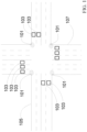
- FIG. 1 is an example of a traffic intersection according to the invention having the features of claim 2.
- the intersection is the area where two or more roads intersect.
- Road (105) and road (107) are examples of roads which intersect.
- the traffic flow through the intersection is controlled by traffic lights (101).
- the traffic light (101) directs the traffic through the use of pre-designated signals such as light colors, or light shape.
- the traffic light (101) lighting pattern is designed so that at any given time, the traffic emanating from one lane would not intersect with traffic emanating from another lane.
- traffic sensors (103) register the passage of an automobile over the sensor.
- Examples of traffic sensors (103) include; induction loops which generate current when a metal body such as an automobile passes over the sensor; Pressure or shear sensors which measure the weight of deformation caused by the passage of an automobile; Acoustic sensors which sense the passage of an automobile; Or image sensors which record and analyze the flow of traffic.
- FIG. 2 is an example of a graph of sensor signal over time.
- the "x" axis depicts the time, while the “y” axis depicts the sensor signal.
- the sensor when an automobile traverses the sensor, the sensor will emit a signal event (201) which corresponds to the time of traversal.
- the period of a green signal, the green light time (203) is depicted as a dashed line.
- FIG. 2 depicts several signal events (201), each signal event (201) corresponding to one automobile traversing the sensor.
- the "usage time” is defined as the sum of all signal events (201) in a lane.
- the “usage percentage” is defined as the "usage time” divided by the green light time (203).
- FIG. 3 is an example of an algorithm for optimizing the traffic flow and which does not suffer from the deficiencies of state of art algorithms.
- Block (301) of the algorithm initializes all the variables required for the algorithm. Examples of variables include; a counter for the traffic lights (e.g. "i”); a timer; a green light time (203 in FIG. 2 ) for each traffic light.
- Block (303) sets the traffic light counter (e.g. "i") to the first traffic light. This facilitates the main loop to start the traffic light cycle.
- Block (305) activates the designated traffic light (e.g. traffic light "i"). In one example, the activation is composed of a sequence of lights leading from a red light to a green light.
- block (305) starts a timer circuit 403 ( FIG. 4 ).
- the timer circuit or timer is used to limit the green light in the traffic light to the green light time (203 in FIG. 2 ).
- Block (307) measures the traffic through the sensor which is relevant for the designated traffic light (e.g. traffic light "i"). If the sensor measurement is positive then block (309) adds the time the sensor is positive to the usage time. If the sensor measurement is zero, then no time is added to the usage time.
- Block (311) compares the timer time to the green light time (e.g., time on, 203 in FIG. 2 ) of the designated traffic light (e.g. traffic light "i"). If the elapsed time is shorter than the green light time (203 in FIG. 2 ), block (307) is executed and the sensor is measured.
- the designated traffic light (e.g. traffic light "i") is deactivated (block 315).
- the deactivation is a sequence of light signals starting with green light and ending with a red light.
- Block (317) checks if the active traffic light is the last of the traffic lights. If the active traffic light is not the last, the traffic light counter (e.g. "i") is changed to reflect the next designated traffic light (e.g. traffic light "i+1") (block 313). The algorithm then executes the loop again for the next designated traffic light (e.g. traffic light "i+1"). If the active traffic light is the last traffic light in the sequence than block (319) is executed and the green light time (203 in FIG. 2 ) duration for each traffic light, is amended based on the usage time measurements.
- the usage time is changed by the following procedure. For the traffic light with the maximum usage percentage increase the green light time (203 in FIG. 2 ) by one unit. If there is more than one traffic light with the same usage percentage as the maximum usage percentage, than randomly choose one of the traffic lights with the maximum usage percentage. For the traffic light with the minimum usage percentage decrease the green light time (203 in FIG. 2 ) by one unit. If there is more than one traffic light with the same usage percentage as the minimum usage percentage, than randomly choose one of the traffic lights with the minimum usage percentage.
- the above described procedure ensures that the total green light time of all the traffic lights is constant, which maintains traffic flow across multiple intersections.
- One example of a time unit is one second. Another example of a time unit is 5 seconds.
- one example is a method for controlling traffic signals comprising: a green light time for each traffic light; measuring usage percentage for each traffic light; increasing the green light time of the traffic light with maximum usage percentage; and reducing the green light time of the traffic light with minimum usage percentage.
- a green light time for each traffic light comprising: measuring usage percentage for each traffic light; increasing the green light time of the traffic light with maximum usage percentage; and reducing the green light time of the traffic light with minimum usage percentage.
- the increase in green light time is a fixed duration.
- the fixed duration is one second.
- the fixed duration is between one second to five seconds.
- the reduction in green light time is a fixed duration.
- the increase and reduction in green light time are equal and of a fixed duration.
- the device for measuring traffic usage comprising of; a traffic sensor; wherein said sensor provides a signal when a vehicle is present in the vicinity of the sensor; a timer device; wherein said timer device provides an electrical signal at a fixed interval; and wherein the output signal of the device is proportional to the duration that a vehicle was present in the vicinity of the traffic sensor to the duration that no vehicle was present in the vicinity of the sensor.
- the device output is an analog signal.
- the device output is a digital signal.
- the algorithm balances the usage for each green light by passing time units from the minimum used direction to the maximum used direction.
- the algorithm changes only the green light duration plan of a traffic light junction, and does not change any other aspect of the junction control, thus do not impair safety of passengers in the junction.
- Common Traffic Light Junctions have one or more predefined green light duration plan which can change according to the time of the day. This algorithm manages and changes the plan continuously to find the plan that optimizes the traffic flow for any predefined green light duration.
- a traffic intersection comprising; two or more intersecting roads; two or more traffic lights; a traffic light controller executing a method for controlling traffic signals comprising: a green light time for each traffic light; measuring usage percentage for each traffic light; increasing the green light time of the traffic light with maximum usage percentage; and reducing the green light time of the traffic light with minimum usage percentage.
- the method for controlling traffic signals is continuously repeated.
- the increase in green light time is a fixed duration.
- the reduction in green light time is a fixed duration.
- the increase and reduction in green light time are equal and of a fixed duration.
- the described algorithm expands on the state of art and resolves the deficiencies of existing solutions namely; the algorithm can be implemented in the existing infrastructure of controllers and single sensor per lane, and the algorithm maintains the traffic flow cycle to prevent disruption to traffic. It is clear that in the implementation of the apparatus and method, many modifications could be made to the system that carries out the described algorithm. It should be considered that all modifications and alterations of the system and algorithm are falling within the scope of this document.
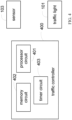
- the operations and algorithms described herein can be implemented as executable code within a micro-controller 400 or control device having processor circuit 401, or stored on a standalone computer or machine readable non-transitory tangible storage medium that are completed based on execution of the code by a processor circuit implemented using one or more integrated circuits.
- Example implementations of the disclosed circuits include hardware logic that is implemented in a logic array such as a programmable logic array (PLA), a field programmable gate array (FPGA), or by mask programming of integrated circuits such as an application-specific integrated circuit (ASIC).
- PLA programmable logic array
- FPGA field programmable gate array
- ASIC application-specific integrated circuit
- any of these circuits also can be implemented using a software-based executable resource that is executed by a corresponding internal processor circuit such as a micro-processor circuit (not shown) and implemented using one or more integrated circuits, where execution of executable code stored in an internal memory circuit causes the integrated circuit(s) implementing the processor circuit to store application state variables in processor memory, creating an executable application resource (e.g., an application instance) that performs the operations of the circuit as described herein.
- a software-based executable resource that is executed by a corresponding internal processor circuit such as a micro-processor circuit (not shown) and implemented using one or more integrated circuits, where execution of executable code stored in an internal memory circuit causes the integrated circuit(s) implementing the processor circuit to store application state variables in processor memory, creating an executable application resource (e.g., an application instance) that performs the operations of the circuit as described herein.
- a software-based executable resource that is executed by a corresponding internal processor circuit such as a micro-processor circuit (not shown)
- circuit refers to both a hardware-based circuit implemented using one or more integrated circuits and that includes logic for performing the described operations, or a software-based circuit that includes a processor circuit (implemented using one or more integrated circuits), the processor circuit including a reserved portion of processor memory for storage of application state data and application variables that are modified by execution of the executable code by a processor circuit.
- a memory circuit 402 can be implemented, for example, using a non-volatile memory such as a programmable read only memory (PROM) or an EPROM, and/or a volatile memory such as a DRAM, etc.
- the micro-controller 400 can be considered to be part of the traffic light controller noted above that is operatively connected with the sensors 103 and the traffic lights 101.
Landscapes
- Physics & Mathematics (AREA)
- General Physics & Mathematics (AREA)
- Traffic Control Systems (AREA)
- Chemical & Material Sciences (AREA)
- Analytical Chemistry (AREA)
Claims (2)
- Verfahren zum Steuern von Verkehrssignalen von Verkehrsampeln (101), wobei jede Verkehrsampel einen Sensor (103) zum Registrieren jedes Signalereignisses (201) aufweist, welches einem den Sensor überquerenden Automobil und einer Grünlichtzeit entspricht, wobei das Verfahren die folgenden Schritte umfasst:Messen des Nutzungsprozentsatzes für jede Verkehrsampel, wobei der Nutzungsprozentsatz die Summe aller Signalereignisse in einer Spur ist, welche von dem jeweiligen Sensor registriert werden, geteilt durch die Grünlichtzeit (203);Erhöhen der Grünlichtzeit der Verkehrsampel mit maximalem Nutzungsgrad um eine Zeitdauer;Verkürzen der Grünlichtzeit der Verkehrsampel mit minimalem Nutzungsanteil um die Zeitdauer;wobei das Erhöhen und das Verkürzen der Grünlichtzeit gleich sind und eine feste Zeitdauer aufweisen;wobei die gesamte Grünlichtzeit aller Verkehrsampeln konstant bleibt und wobei das Verfahren kontinuierlich wiederholt wird.
- Eine Verkehrskreuzung mit;zwei oder mehr sich kreuzende Straßen (105, 107);zwei oder mehr Verkehrsampeln (101), die jeweils einen Sensor (103) zur Registrierung jedes Signalereignisses (201), welches einem den Sensor überquerenden Automobil und einer Grünlichtzeit entsprich, aufweisen;ein Verkehrsampel-Steuergerät, das so konstruiert und dazu eingerichtet ist, dass es Verkehrssignale steuert, indem es den Nutzungsprozentsatz für jede Verkehrsampel misst, wobei der Nutzungsprozentsatz die Summe aller Signalereignisse in einer Spur ist, die von dem jeweiligen Sensor registriert werden, geteilt durch die Grünlichtzeit (203); die Grünlichtzeit der Verkehrsampel mit maximalem Nutzungsprozentsatz um eine Zeitdauer erhöht; und die Grünlichtzeit der Verkehrsampel mit minimalem Nutzungsprozentsatz um die Zeitdauer verringert;wobei das Erhöhen und das Verkürzen der Grünlichtzeit gleich sind und eine feste Zeitdauer aufweisen;wobei die gesamte Grünlichtzeit aller Verkehrsampeln konstant bleibt.
Applications Claiming Priority (2)
| Application Number | Priority Date | Filing Date | Title |
|---|---|---|---|
| US201562215320P | 2015-09-08 | 2015-09-08 | |
| PCT/IL2016/050940 WO2017042800A1 (en) | 2015-09-08 | 2016-08-28 | Method for traffic control |
Publications (4)
| Publication Number | Publication Date |
|---|---|
| EP3357048A1 EP3357048A1 (de) | 2018-08-08 |
| EP3357048A4 EP3357048A4 (de) | 2020-03-11 |
| EP3357048B1 true EP3357048B1 (de) | 2024-10-02 |
| EP3357048C0 EP3357048C0 (de) | 2024-10-02 |
Family
ID=58190612
Family Applications (1)
| Application Number | Title | Priority Date | Filing Date |
|---|---|---|---|
| EP16843836.4A Active EP3357048B1 (de) | 2015-09-08 | 2016-08-28 | Verfahren zur verkehrsregelung |
Country Status (4)
| Country | Link |
|---|---|
| US (1) | US10121369B2 (de) |
| EP (1) | EP3357048B1 (de) |
| IL (1) | IL257446A (de) |
| WO (1) | WO2017042800A1 (de) |
Families Citing this family (12)
| Publication number | Priority date | Publication date | Assignee | Title |
|---|---|---|---|---|
| CN107545740A (zh) * | 2017-09-04 | 2018-01-05 | 吴世贵 | 一种交通灯车控制方法 |
| CN108171999B (zh) * | 2018-02-11 | 2021-02-02 | 成都信息工程大学 | 基于滑动平均车流量的红绿灯时长动态控制方法及系统 |
| CN108898855B (zh) * | 2018-09-07 | 2021-05-28 | 江苏智通交通科技有限公司 | 路口信号相位方案绿灯时长配置方法 |
| CN110491138A (zh) * | 2019-07-30 | 2019-11-22 | 广东天机工业智能系统有限公司 | 交通灯控制系统及其控制方法 |
| CN111047865B (zh) * | 2019-12-18 | 2020-11-24 | 南京林业大学 | 自动驾驶环境下单向通行道路相交路口通行控制方法 |
| US10930146B1 (en) | 2019-12-23 | 2021-02-23 | Continental Automotive Systems, Inc. | Traffic control system and method for operating same |
| CN111554106A (zh) * | 2020-03-23 | 2020-08-18 | 浙江大华技术股份有限公司 | 交叉口感应信号控制的方法、设备和计算机设备 |
| CN111429721B (zh) * | 2020-03-27 | 2021-11-09 | 江苏智通交通科技有限公司 | 基于排队消散时间的路口交通信号方案优化方法 |
| CN111882887B (zh) * | 2020-07-16 | 2021-11-23 | 浙江工业大学 | 同步展示scats相位信号及整合流量设备监测数据的方法 |
| CN113516856B (zh) * | 2021-06-23 | 2022-11-04 | 东南大学 | 考虑道路运行速度与交叉口交通状态的干线协调控制方法 |
| CN113593274B (zh) * | 2021-07-29 | 2023-05-02 | 青岛海信网络科技股份有限公司 | 一种交通信号控制方法及装置 |
| CN116229740B (zh) * | 2023-05-10 | 2023-10-10 | 湖北大学 | 一种红绿灯配时控制方法及系统 |
Family Cites Families (11)
| Publication number | Priority date | Publication date | Assignee | Title |
|---|---|---|---|---|
| US3258744A (en) | 1963-02-20 | 1966-06-28 | Vehicle traffic control system | |
| US6822556B2 (en) * | 2002-07-17 | 2004-11-23 | Kidlights, Llc | Methods and apparatus for a multi-mode night-light configured to emulate a traffic signal |
| US7821422B2 (en) * | 2003-08-18 | 2010-10-26 | Light Vision Systems, Inc. | Traffic light signal system using radar-based target detection and tracking |
| US8112220B2 (en) * | 2006-05-03 | 2012-02-07 | International Business Machines Corporation | Management of traffic signals at road intersection to avoid blocking vehicles |
| KR20090008964A (ko) * | 2007-07-19 | 2009-01-22 | 주식회사 디스엔지니어링 | 차량 수에 따른 교통 신호등 제어 장치 |
| TWI384429B (zh) * | 2008-05-28 | 2013-02-01 | Univ Nat Kaohsiung 1St Univ Sc | Led驅動電路,運用該電路之交通號誌,及交通號誌管理系統與方法 |
| US8040254B2 (en) * | 2009-01-06 | 2011-10-18 | International Business Machines Corporation | Method and system for controlling and adjusting traffic light timing patterns |
| CN101923784A (zh) * | 2009-06-17 | 2010-12-22 | 鸿富锦精密工业(深圳)有限公司 | 交通信号灯调整系统及方法 |
| KR20130015802A (ko) * | 2011-08-05 | 2013-02-14 | 이흥수 | 계층적 구조의 식별정보를 이용한 교통 신호 제어 장치 및 방법 |
| US8842022B2 (en) * | 2012-05-10 | 2014-09-23 | Ms Sedco, Inc. | System and method for configuring a traffic control sensor system |
| CA2955961A1 (en) * | 2014-07-28 | 2016-02-04 | Econolite Group, Inc. | Self-configuring traffic signal controller |
-
2016
- 2016-08-18 US US15/240,366 patent/US10121369B2/en active Active
- 2016-08-28 WO PCT/IL2016/050940 patent/WO2017042800A1/en not_active Ceased
- 2016-08-28 EP EP16843836.4A patent/EP3357048B1/de active Active
-
2018
- 2018-02-10 IL IL257446A patent/IL257446A/en unknown
Also Published As
| Publication number | Publication date |
|---|---|
| IL257446A (en) | 2018-04-30 |
| WO2017042800A1 (en) | 2017-03-16 |
| US10121369B2 (en) | 2018-11-06 |
| EP3357048A4 (de) | 2020-03-11 |
| EP3357048A1 (de) | 2018-08-08 |
| US20170069204A1 (en) | 2017-03-09 |
| EP3357048C0 (de) | 2024-10-02 |
Similar Documents
| Publication | Publication Date | Title |
|---|---|---|
| EP3357048B1 (de) | Verfahren zur verkehrsregelung | |
| US10529230B2 (en) | Method for traffic control | |
| US10803742B2 (en) | Method for traffic control | |
| US11823573B2 (en) | Signal control apparatus and signal control method based on reinforcement learning | |
| JP6517098B2 (ja) | 信号機制御システム及び信号機制御方法 | |
| US10198941B2 (en) | Method and apparatus for evaluating traffic approaching a junction at a lane level | |
| US9640071B2 (en) | Method and apparatus for identifying a bi-modality condition upstream of diverging road segments | |
| US20130285840A1 (en) | Control of traffic signal due to obstructed view | |
| US10643465B1 (en) | Dynamic advanced traffic detection from assessment of dilemma zone activity for enhancement of intersection traffic flow and adjustment of timing of signal phase cycles | |
| CN104537851B (zh) | 实时反馈动态交通信号控制系统 | |
| CN109754619A (zh) | 单点交通信号控制方法、装置、交通信号机及存储介质 | |
| US8140251B2 (en) | Management of traffic signals at road intersection to avoid blocking vehicles | |
| US20220270480A1 (en) | Signal control apparatus and method based on reinforcement learning | |
| CN105608894B (zh) | 一种确定突发性拥堵状态的方法及装置 | |
| JP2016170642A (ja) | 表示制御指示ユニット、信号表示制御システム、表示制御指示方法、および表示制御指示プログラム | |
| Ma et al. | A method of signal timing optimization for spillover dissipation in urban street networks | |
| CN104318790B (zh) | 一种交通信号灯配置方法及装置 | |
| CN114333354B (zh) | 路口调度方法和系统 | |
| CN112330957B (zh) | 一种路口信号灯控制效果分析系统及方法 | |
| CN111402571A (zh) | 一种勤务车队冲突异常预警及调整方案生成的方法及装置 | |
| Sahraei et al. | Determination of gap acceptance at priority intersections | |
| WO2016203618A1 (ja) | 運転支援装置及び車両 | |
| JP2011029014A (ja) | 傾斜検出方法及び傾斜検出装置 | |
| Alkandari et al. | Theory of dynamic fuzzy logic traffic light integrated system with accident detection and action | |
| KR101158405B1 (ko) | 다차로용 기준 검지기 |
Legal Events
| Date | Code | Title | Description |
|---|---|---|---|
| STAA | Information on the status of an ep patent application or granted ep patent |
Free format text: STATUS: THE INTERNATIONAL PUBLICATION HAS BEEN MADE |
|
| PUAI | Public reference made under article 153(3) epc to a published international application that has entered the european phase |
Free format text: ORIGINAL CODE: 0009012 |
|
| STAA | Information on the status of an ep patent application or granted ep patent |
Free format text: STATUS: REQUEST FOR EXAMINATION WAS MADE |
|
| 17P | Request for examination filed |
Effective date: 20180406 |
|
| AK | Designated contracting states |
Kind code of ref document: A1 Designated state(s): AL AT BE BG CH CY CZ DE DK EE ES FI FR GB GR HR HU IE IS IT LI LT LU LV MC MK MT NL NO PL PT RO RS SE SI SK SM TR |
|
| AX | Request for extension of the european patent |
Extension state: BA ME |
|
| DAV | Request for validation of the european patent (deleted) | ||
| DAX | Request for extension of the european patent (deleted) | ||
| RIC1 | Information provided on ipc code assigned before grant |
Ipc: G08G 1/16 20060101ALI20191101BHEP Ipc: G08G 1/01 20060101AFI20191101BHEP Ipc: G08G 1/09 20060101ALI20191101BHEP Ipc: G08G 1/0967 20060101ALI20191101BHEP Ipc: G08G 1/08 20060101ALI20191101BHEP Ipc: G08G 1/095 20060101ALI20191101BHEP Ipc: G08G 1/07 20060101ALI20191101BHEP |
|
| A4 | Supplementary search report drawn up and despatched |
Effective date: 20200211 |
|
| RIC1 | Information provided on ipc code assigned before grant |
Ipc: G08G 1/0967 20060101ALI20200205BHEP Ipc: G08G 1/09 20060101ALI20200205BHEP Ipc: G08G 1/16 20060101ALI20200205BHEP Ipc: G08G 1/08 20060101ALI20200205BHEP Ipc: G08G 1/01 20060101AFI20200205BHEP Ipc: G08G 1/095 20060101ALI20200205BHEP Ipc: G08G 1/07 20060101ALI20200205BHEP |
|
| STAA | Information on the status of an ep patent application or granted ep patent |
Free format text: STATUS: EXAMINATION IS IN PROGRESS |
|
| 17Q | First examination report despatched |
Effective date: 20211111 |
|
| REG | Reference to a national code |
Ipc: G08G0001020000 Ref country code: DE Ref legal event code: R079 Ref document number: 602016089682 Country of ref document: DE Free format text: PREVIOUS MAIN CLASS: G08G0001010000 Ipc: G08G0001020000 |
|
| RIC1 | Information provided on ipc code assigned before grant |
Ipc: G08G 1/083 20060101ALI20240214BHEP Ipc: G08G 1/04 20060101ALI20240214BHEP Ipc: G08G 1/02 20060101AFI20240214BHEP |
|
| GRAP | Despatch of communication of intention to grant a patent |
Free format text: ORIGINAL CODE: EPIDOSNIGR1 |
|
| STAA | Information on the status of an ep patent application or granted ep patent |
Free format text: STATUS: GRANT OF PATENT IS INTENDED |
|
| INTG | Intention to grant announced |
Effective date: 20240424 |
|
| GRAS | Grant fee paid |
Free format text: ORIGINAL CODE: EPIDOSNIGR3 |
|
| GRAA | (expected) grant |
Free format text: ORIGINAL CODE: 0009210 |
|
| STAA | Information on the status of an ep patent application or granted ep patent |
Free format text: STATUS: THE PATENT HAS BEEN GRANTED |
|
| AK | Designated contracting states |
Kind code of ref document: B1 Designated state(s): AL AT BE BG CH CY CZ DE DK EE ES FI FR GB GR HR HU IE IS IT LI LT LU LV MC MK MT NL NO PL PT RO RS SE SI SK SM TR |
|
| REG | Reference to a national code |
Ref country code: GB Ref legal event code: FG4D |
|
| REG | Reference to a national code |
Ref country code: CH Ref legal event code: EP |
|
| REG | Reference to a national code |
Ref country code: DE Ref legal event code: R096 Ref document number: 602016089682 Country of ref document: DE |
|
| REG | Reference to a national code |
Ref country code: IE Ref legal event code: FG4D |
|
| U01 | Request for unitary effect filed |
Effective date: 20241023 |
|
| U07 | Unitary effect registered |
Designated state(s): AT BE BG DE DK EE FI FR IT LT LU LV MT NL PT RO SE SI Effective date: 20241113 |
|
| PG25 | Lapsed in a contracting state [announced via postgrant information from national office to epo] |
Ref country code: IS Free format text: LAPSE BECAUSE OF FAILURE TO SUBMIT A TRANSLATION OF THE DESCRIPTION OR TO PAY THE FEE WITHIN THE PRESCRIBED TIME-LIMIT Effective date: 20250202 Ref country code: HR Free format text: LAPSE BECAUSE OF FAILURE TO SUBMIT A TRANSLATION OF THE DESCRIPTION OR TO PAY THE FEE WITHIN THE PRESCRIBED TIME-LIMIT Effective date: 20241002 |
|
| PG25 | Lapsed in a contracting state [announced via postgrant information from national office to epo] |
Ref country code: ES Free format text: LAPSE BECAUSE OF FAILURE TO SUBMIT A TRANSLATION OF THE DESCRIPTION OR TO PAY THE FEE WITHIN THE PRESCRIBED TIME-LIMIT Effective date: 20241002 |
|
| PG25 | Lapsed in a contracting state [announced via postgrant information from national office to epo] |
Ref country code: NO Free format text: LAPSE BECAUSE OF FAILURE TO SUBMIT A TRANSLATION OF THE DESCRIPTION OR TO PAY THE FEE WITHIN THE PRESCRIBED TIME-LIMIT Effective date: 20250102 |
|
| PG25 | Lapsed in a contracting state [announced via postgrant information from national office to epo] |
Ref country code: GR Free format text: LAPSE BECAUSE OF FAILURE TO SUBMIT A TRANSLATION OF THE DESCRIPTION OR TO PAY THE FEE WITHIN THE PRESCRIBED TIME-LIMIT Effective date: 20250103 |
|
| PG25 | Lapsed in a contracting state [announced via postgrant information from national office to epo] |
Ref country code: PL Free format text: LAPSE BECAUSE OF FAILURE TO SUBMIT A TRANSLATION OF THE DESCRIPTION OR TO PAY THE FEE WITHIN THE PRESCRIBED TIME-LIMIT Effective date: 20241002 Ref country code: CZ Free format text: LAPSE BECAUSE OF FAILURE TO SUBMIT A TRANSLATION OF THE DESCRIPTION OR TO PAY THE FEE WITHIN THE PRESCRIBED TIME-LIMIT Effective date: 20241002 |
|
| PG25 | Lapsed in a contracting state [announced via postgrant information from national office to epo] |
Ref country code: RS Free format text: LAPSE BECAUSE OF FAILURE TO SUBMIT A TRANSLATION OF THE DESCRIPTION OR TO PAY THE FEE WITHIN THE PRESCRIBED TIME-LIMIT Effective date: 20250102 |
|
| PG25 | Lapsed in a contracting state [announced via postgrant information from national office to epo] |
Ref country code: SM Free format text: LAPSE BECAUSE OF FAILURE TO SUBMIT A TRANSLATION OF THE DESCRIPTION OR TO PAY THE FEE WITHIN THE PRESCRIBED TIME-LIMIT Effective date: 20241002 |
|
| PG25 | Lapsed in a contracting state [announced via postgrant information from national office to epo] |
Ref country code: SK Free format text: LAPSE BECAUSE OF FAILURE TO SUBMIT A TRANSLATION OF THE DESCRIPTION OR TO PAY THE FEE WITHIN THE PRESCRIBED TIME-LIMIT Effective date: 20241002 |
|
| PLBE | No opposition filed within time limit |
Free format text: ORIGINAL CODE: 0009261 |
|
| STAA | Information on the status of an ep patent application or granted ep patent |
Free format text: STATUS: NO OPPOSITION FILED WITHIN TIME LIMIT |
|
| 26N | No opposition filed |
Effective date: 20250703 |