EP3356006B1 - Vorrichtung zur umwandlung einer flüssigkeit in dampf und zugehöriges verfahren zur regelung einer heizleistung - Google Patents
Vorrichtung zur umwandlung einer flüssigkeit in dampf und zugehöriges verfahren zur regelung einer heizleistung Download PDFInfo
- Publication number
- EP3356006B1 EP3356006B1 EP16777952.9A EP16777952A EP3356006B1 EP 3356006 B1 EP3356006 B1 EP 3356006B1 EP 16777952 A EP16777952 A EP 16777952A EP 3356006 B1 EP3356006 B1 EP 3356006B1
- Authority
- EP
- European Patent Office
- Prior art keywords
- temperature
- power
- liquid
- heating
- heating power
- Prior art date
- Legal status (The legal status is an assumption and is not a legal conclusion. Google has not performed a legal analysis and makes no representation as to the accuracy of the status listed.)
- Active
Links
Images
Classifications
-
- B—PERFORMING OPERATIONS; TRANSPORTING
- B01—PHYSICAL OR CHEMICAL PROCESSES OR APPARATUS IN GENERAL
- B01D—SEPARATION
- B01D1/00—Evaporating
- B01D1/0011—Heating features
- B01D1/0017—Use of electrical or wave energy
-
- B—PERFORMING OPERATIONS; TRANSPORTING
- B01—PHYSICAL OR CHEMICAL PROCESSES OR APPARATUS IN GENERAL
- B01D—SEPARATION
- B01D1/00—Evaporating
- B01D1/0082—Regulation; Control
-
- B—PERFORMING OPERATIONS; TRANSPORTING
- B01—PHYSICAL OR CHEMICAL PROCESSES OR APPARATUS IN GENERAL
- B01D—SEPARATION
- B01D1/00—Evaporating
- B01D1/02—Evaporators with heating coils
-
- B—PERFORMING OPERATIONS; TRANSPORTING
- B01—PHYSICAL OR CHEMICAL PROCESSES OR APPARATUS IN GENERAL
- B01D—SEPARATION
- B01D1/00—Evaporating
- B01D1/14—Evaporating with heated gases or vapours or liquids in contact with the liquid
-
- B—PERFORMING OPERATIONS; TRANSPORTING
- B01—PHYSICAL OR CHEMICAL PROCESSES OR APPARATUS IN GENERAL
- B01D—SEPARATION
- B01D3/00—Distillation or related exchange processes in which liquids are contacted with gaseous media, e.g. stripping
- B01D3/34—Distillation or related exchange processes in which liquids are contacted with gaseous media, e.g. stripping with one or more auxiliary substances
- B01D3/343—Distillation or related exchange processes in which liquids are contacted with gaseous media, e.g. stripping with one or more auxiliary substances the substance being a gas
- B01D3/346—Distillation or related exchange processes in which liquids are contacted with gaseous media, e.g. stripping with one or more auxiliary substances the substance being a gas the gas being used for removing vapours, e.g. transport gas
-
- F—MECHANICAL ENGINEERING; LIGHTING; HEATING; WEAPONS; BLASTING
- F22—STEAM GENERATION
- F22B—METHODS OF STEAM GENERATION; STEAM BOILERS
- F22B1/00—Methods of steam generation characterised by form of heating method
- F22B1/28—Methods of steam generation characterised by form of heating method in boilers heated electrically
- F22B1/287—Methods of steam generation characterised by form of heating method in boilers heated electrically with water in sprays or in films
-
- F—MECHANICAL ENGINEERING; LIGHTING; HEATING; WEAPONS; BLASTING
- F22—STEAM GENERATION
- F22B—METHODS OF STEAM GENERATION; STEAM BOILERS
- F22B1/00—Methods of steam generation characterised by form of heating method
- F22B1/28—Methods of steam generation characterised by form of heating method in boilers heated electrically
- F22B1/30—Electrode boilers
-
- F—MECHANICAL ENGINEERING; LIGHTING; HEATING; WEAPONS; BLASTING
- F22—STEAM GENERATION
- F22B—METHODS OF STEAM GENERATION; STEAM BOILERS
- F22B35/00—Control systems for steam boilers
- F22B35/005—Control systems for instantaneous steam boilers
-
- Y—GENERAL TAGGING OF NEW TECHNOLOGICAL DEVELOPMENTS; GENERAL TAGGING OF CROSS-SECTIONAL TECHNOLOGIES SPANNING OVER SEVERAL SECTIONS OF THE IPC; TECHNICAL SUBJECTS COVERED BY FORMER USPC CROSS-REFERENCE ART COLLECTIONS [XRACs] AND DIGESTS
- Y02—TECHNOLOGIES OR APPLICATIONS FOR MITIGATION OR ADAPTATION AGAINST CLIMATE CHANGE
- Y02E—REDUCTION OF GREENHOUSE GAS [GHG] EMISSIONS, RELATED TO ENERGY GENERATION, TRANSMISSION OR DISTRIBUTION
- Y02E60/00—Enabling technologies; Technologies with a potential or indirect contribution to GHG emissions mitigation
- Y02E60/30—Hydrogen technology
- Y02E60/36—Hydrogen production from non-carbon containing sources, e.g. by water electrolysis
Definitions
- the invention relates to the field of steam generators, and in particular to steam generators used in high temperature steam electrolysers (EHVT).
- EHVT high temperature steam electrolysers
- the invention relates more particularly to a device for converting a liquid into vapor capable of supplying a low vapor flow rate, in particular a vapor flow rate of in particular between 10 g / h and 10 kg / h, and operating at constant pressure, in particular at atmospheric pressure or under a few tens of bars.
- the invention also relates to the method of regulating the heating power of the device for converting a liquid into vapor.
- a high temperature water vapor electrolyser (EVHT, acronym for “High Temperature Water Vapor Electrolysis”, or HTSE acronym for “ High Temperature Steam Electrolysis ”) is an electrochemical device for the production of hydrogen from water vapor by applying an electric current to a stack of electrolytic cells electrically connected in series, each consisting of two electrodes, namely a cathode and an anode, intercalating a solid oxide electrolytic membrane. Overall, water vapor is introduced at the cathode of each cell supplied with electricity, and an electrochemical reduction reaction of the water vapor leads to the formation of hydrogen on the cathode.
- EVHT acronym for "High Temperature Water Vapor Electrolysis”
- HTSE High Temperature Steam Electrolysis
- an electrolyser is a system very sensitive to inhomogeneities of gas current / flow, these homogeneities can in fact lead to premature aging of the electrolyser. For example, if the vapor flow rate varies around its set value, an instability of the electrolyser operating point can be observed, which results in variations in the voltage of the cells, the cause of premature aging. More seriously, strong variations in the flow of steam result in pressure variations of a few tens or hundreds of mbar, which may be sufficient to damage the seals or crack the electrochemical cells themselves. The most homogeneous and regular possible flow of steam is therefore sought.
- Steam generating devices generally include a heated evaporation surface, on which a liquid is deposited so as to generate the evaporation of the liquid.
- a heated evaporation surface on which a liquid is deposited so as to generate the evaporation of the liquid.
- the document WO 2000/29787 describes an iron capable of producing steam to improve ironing.
- the quantity of vapor produced can be regulated over time by modulating the flow rate of liquid which is deposited on the heating surface.
- Other devices for generating steam are known, for example documents US2010 / 0025341A1 and FR1060544 .
- transient overpressures also called bursts of vapor.
- These transient overpressures are due to the fact that the liquid will cover a larger part of the heating surface, in particular areas located at a temperature above the boiling point, leading to uncontrolled point vaporization.
- These transient overpressures also appear in the transient phases corresponding to a change in the flow rate setpoint.
- buffer volumes can be a solution to limit transient overpressures, but this solution has the disadvantage of reducing the reactivity of the steam generator during changes of setpoint and increases the complexity of the evaporator, especially in the case of 'an evaporator designed to operate at a pressure greater than atmospheric pressure. Moreover, even if this solution reduces the amplitude of the overpressures, this solution does not eliminate them.
- the technical problem of the invention is to limit the transient overpressures of a device for converting a liquid into vapor.
- the present invention proposes to solve this technical problem by modulating the heating power of the heating surface as a function of the flow rate and as a function of a temperature of the heating surface.
- the control unit is configured to control a heating power of the heating means as a function of a flow rate and a temperature measured by the temperature sensor according to a predetermined control law, said predetermined control law changing, for each flow rate, non-linearly and inversely proportional to the difference between a reference temperature of the enclosure and the temperature measured by the temperature sensor.
- the invention thus makes it possible to control the temperature of the heating surface as a function of the flow rate and as a function of a residual temperature in the chamber containing the heating surface.
- the invention avoids overheating or underheating the heating surface with respect to the energy required to allow evaporation of the liquid, thus limiting transient overpressures.
- the flow change phases are also anticipated to avoid transient overpressures.
- the non-linear and inversely proportional evolution of the control law makes it possible, at low flow, to anticipate an increase in flow by overheating the heating surface in a reasonable manner above the reference temperature. Conversely, at high flow, the evolution of the control law makes it possible to anticipate a reduction of the flow rate by reducing the heating power of the heating surface in a reasonable manner below the reference temperature.
- the regulation of the heating surface also allows operation at a low average temperature, that is to say of the order of 100 ° C. above the boiling point of the liquid, which limits heat losses.
- the device is particularly simple to implement, since it requires a single temperature sensor.
- the temperature sensor is positioned at one end of the evaporating surface opposite the end connected to the liquid inlet.
- the end of the evaporating surface is meant the part of the evaporating surface which extends to a length of 1/3 of the evaporating surface starting from the end opposite to. the end connected to the liquid inlet. Positioning this temperature sensor opposite the liquid inlet makes it possible to limit the interaction of the sensor with the liquid.
- the device also comprises a gas inlet opening into the enclosure and a second flow regulator arranged at the level of the gas inlet, the control unit being configured to control a heating power of the means. heating as a function of a flow rate from the first flow regulator, a flow rate from the second flow regulator and a temperature measured by the temperature sensor according to a predetermined control law.
- This embodiment makes it possible to combine the evaporation of the liquid with a gas to form a gas mixture with a controlled concentration.
- the device could include several gas inlets without changing the invention.
- the theoretical heating power to be applied to the heating surface makes it possible to distribute the liquid over practically the entire length of the heating surface, but this is not sufficient to obtain good operation, in particular during changes in the flow rate setpoint. It is in fact advisable, at low flow, to anticipate an increase in flow by superheating the heating surface in a reasonable manner above the reference temperature. Conversely, at high flow rate, it is no longer possible to maintain the entire heating surface at the reference temperature since it is covered with liquid over a great length. However, in this case, it may be necessary to apply a lot of power if the liquid is likely to reach the bottom of the chamber, an area in which it will be very poorly vaporized.
- the invention therefore consists in defining, for each flow rate of liquid to be vaporized, a correction of the power to be applied to the heating surface as a function of the measured temperature measurement.
- the calculation of the theoretical heating power corresponds to the maximum power of the means. of heating in percentage multiplied by the flow divided by a coefficient added with the flow of the second flow regulator divided by a second coefficient.
- This embodiment makes it possible to add the contribution of the gas flow rate to be heated divided by a second coefficient taking into account the specific heat of the gas considered.
- the first coefficient is determined as a function of the latent heat of vaporization of the liquid considered and of the specific heat of the vapor then refined by experimental tests to take account of the thermal losses.
- the reference temperature corresponds to an average temperature chosen for the operation of the device for converting a liquid into vapor, the reference temperature being higher than the vaporization temperature of the liquid.
- This embodiment makes it possible to regulate the operating enclosure at a temperature at least equal to the reference temperature to avoid any risk of vapor condensation.
- the regulation makes it possible to center the operating temperature of the device on the reference temperature, with an operating temperature range between a first temperature threshold and a third temperature threshold.
- the proposed algorithm allows self-adaptation during a change in flow rate thanks to the measured temperature which reflects the history of use of the device. Indeed, in practice, the measured temperature is inversely proportional to the quantity of liquid evaporated during the preceding instants.
- the step of correcting the theoretical heating power comprises the following step: if the measured temperature is greater than a fourth temperature threshold, the power is corrected by subtracting the maximum power of the means of percentage heating multiplied with a fifth coefficient, the fourth temperature threshold being chosen greater than the third temperature threshold.
- This embodiment makes it possible to limit the power setpoint applied to the heating surface.
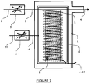
- the figure 1 illustrates a device for converting a liquid into vapor comprising an enclosure 6 provided with a vapor outlet 4 and a liquid inlet 2 coupled to a first conventional flow regulator 9 itself supplied by a liquid inlet 1.
- the first flow regulator 9 can be a commercial regulator, for example a thermal or Coriolis mass flow regulator.
- the enclosure 6 contains various elements ensuring the conversion of liquid into vapor, in particular a propeller 3 in which is inserted a wired electrical heating resistance, for example of round section, acting as heating surface 7 and evaporation surface 17.
- a temperature sensor 8 is installed in the lower part of the propeller 3 in contact with the resistance electric.
- a thermal insulating envelope 5 is placed on the wall of the steam generator to avoid cold spots. Preferably, the casing 5 is maintained at a temperature much higher than the boiling point of the liquid.
- a gas flow regulator 11 supplied by a gas line 10 is connected to the steam generator by an inlet 12 with the aim of allowing the production of a gas mixture.
- a control unit is connected to the first regulator 9, to the second regulator 11, to the temperature sensor 8 and to the electrical resistance so as to control a flow rate D L in the first regulator 9, a flow rate D g in the second regulator and a heating power P of the electric resistance.
- the heating power P of the electric resistance is controlled as a function of the flow rates D L and D g and the temperature T measured by the temperature sensor 8 according to a control law.
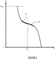
- the figure 2 illustrates this power control law P for two particular flow rates D L and D g as a function of temperature T.
- the control law is centered on a reference temperature T ref , and evolves in a non-linear fashion and inversely proportional to l 'difference between the reference temperature T ref and the measured temperature T.
- the power P is represented between zero Watt and the maximum power P MAX of the heating surface 7.
- the theoretical power P T is positioned on part 20 of the law of control when the flow rates D L and D g are low, this makes it possible to anticipate an increase in flow rate since the system operates at a temperature greater than T ref .
- part 21 represents this theoretical power P T when the flow rates D L and D g are high with anticipation of a drop in these flow rates since the system operates at a temperature below T ref .
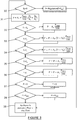
- the figure 3 illustrates a flowchart of the method for regulating the power P implemented with very simple functions, such as comparisons, addition, subtraction or multiplication.
- the flowchart represents an automated loop of tests and calculations which results in a power value P which is applied to the heating surface 7.
- a first step 30 when the generator does not vaporize liquid, that is to say when the flow regulator 9 has a zero setpoint, then the power P is adapted to maintain the heating cord at the reference temperature T ref .
- This regulation can be carried out by a conventional regulation, threshold or PID type.
- a theoretical power P T is calculated as a function of the flow of liquid to be evaporated.
- the power P to be applied to the heating cord is therefore initialized with this theoretical value P T and will be adapted in the following steps as a function of the temperature T.
- P P T
- Steps 37 and 38 make it possible to limit the values of the power P. If the result of the above calculations gives a value P less than zero, then P is fixed at zero. If the result of the above calculations gives a value P greater than P MAX then P is set to P MAX . Finally, in step 39, the power setpoint P is applied to the heating surface 7, then the test loop begins again.
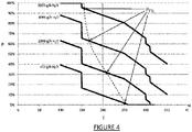
- the figure 4 illustrates the particular case of a device for converting water into steam, integrating gas supplies with hydrogen and nitrogen.
- the maximum water flow rate is 6400 g / h, that of hydrogen is 500 1 / h and that of nitrogen is 1000 1 / h.
- the maximum power P Max of the heating resistor is 6000W.
- the reference temperature T ref is between 150 ° C and 250 ° C. In the example of figure 4 , the reference temperature T ref is set at 200 ° C, ie 100 ° C above the boiling point of water.
- the power P is adapted to maintain the heating cord at the reference temperature T ref is 200 ° C.
- the value of the temperature thresholds and of the coefficients can vary without changing the invention.
- the first temperature threshold T 1 can be between 140 ° C and 175 ° C.
- the second temperature threshold T 2 can be between 220 ° C and 280 ° C.
- the third temperature threshold T 3 can be between 280 ° C and 350 ° C.
- the fourth temperature threshold T 4 can be between 300 ° C and 350 ° C.
- the coefficients A 1 , A 2 and A 3 can be between 1.05 and 10.
- the coefficients A 4 and A 5 can be between 0.1 and 1.
- the figure 4 illustrates the evolution of the power P as a function of the measured temperature T corresponding to typical production values covering the entire production range with 100g / h, 2000g / h, 4000g / h and 6000g / h.
- the theoretical power P T is located above the reference temperature (200 ° C) at low flow (100g / h, 2000g / h) and below this temperature at high flow (4000g / h and 6000g / h) .
Landscapes
- Engineering & Computer Science (AREA)
- Chemical & Material Sciences (AREA)
- Chemical Kinetics & Catalysis (AREA)
- Physics & Mathematics (AREA)
- Thermal Sciences (AREA)
- Mechanical Engineering (AREA)
- General Engineering & Computer Science (AREA)
- Life Sciences & Earth Sciences (AREA)
- Sustainable Energy (AREA)
- Sustainable Development (AREA)
- Combustion & Propulsion (AREA)
- Control Of Resistance Heating (AREA)
- Control Of Steam Boilers And Waste-Gas Boilers (AREA)
- Electrolytic Production Of Non-Metals, Compounds, Apparatuses Therefor (AREA)
- Vaporization, Distillation, Condensation, Sublimation, And Cold Traps (AREA)
- Investigating Or Analyzing Materials Using Thermal Means (AREA)
Claims (10)
- Vorrichtung zum Umwandeln einer Flüssigkeit in Dampf für Hochtemperatur-Wasserdampf-Elektrolyseur, wobei die Vorrichtung enthält- eine Verdampfungsfläche (17),- einen Flüssigkeitseinlass (2), verbunden mit der Verdampfungsfläche (17),- eine Heizung zum Erwärmen (7) der Verdampfungsfläche (17),- einen Durchflussregler (9), angeordnet in Höhe des Flüssigkeitseinlasses (2),- und eine Steuereinheit, konfiguriert zur Steuerung einer Durchflussmenge (DL), die vom Durchflussregler (9) in den Flüssigkeitseinlass (2) eingespritzt wird,dadurch gekennzeichnet, dass :- die Vorrichtung auch beinhaltet:• eine Kammer (6), die die Verdampfungsfläche (17) enthält, und eine Spiralform hat, diese Kammer (6) weist eine Öffnung auf, die mit dem Flüssigkeitseinlass (2) und einem Dampfauslass (4) verbunden ist, und• einen Temperatursensor (8), angeordnet auf der Verdampfungsfläche (17),- und dadurch, dass die Steuereinheit konfiguriert ist, um eine Heizleistung (P) der Heizung (7) in Abhängigkeit von der Durchflussmenge (DL) und einer Temperatur (T) zu steuern, gemessen vom Temperatursensor (8) nach einem vorher festgelegten Regelgesetz, dieses vorher festgelegte Regelgesetz entwickelt sich, für jede Durchflussmenge (DL), in nicht-linearer Art und Weise, umgekehrt proportional zum Abstand zwischen einer Referenztemperatur (Tref) der Kammer (6) und der vom Temperatursensor (8) gemessenen Temperatur (T).
- Vorrichtung zum Umwandeln einer Flüssigkeit in Dampf nach Anspruch 1, dadurch gekennzeichnet, dass der Temperatursensor (8) in Höhe eines Endstücks der Verdampfungsfläche (17) angeordnet ist, das dem mit dem Flüssigkeitseinlass (2) verbundenen Endstück gegenüberliegt.
- Vorrichtung zum Umwandeln einer Flüssigkeit in Dampf nach einem der Ansprüche 1 bis 2, dadurch gekennzeichnet, dass sie auch einen Gaseinlass (12) enthält, der in der Kammer (6) mündet und einen zweiten Durchflussregler (11), angeordnet in Höhe des Gaseinlasses (12), die Steuereinheit ist dabei dazu konfiguriert, eine Heizleistung (P) der Heizung (7) in Abhängigkeit von einer Durchflussmenge (DL) des ersten Durchflussreglers (9), einer Durchflussmenge (Dg) des zweiten Durchflussreglers (11) und einer Temperatur (T), gemessen vom Temperatursensor (8) nach einem vorher festgelegten Regelgesetz, zu steuern.
- Verfahren zur Steuerung der Heizleistung (P) einer Vorrichtung zum Umwandeln einer Flüssigkeit in Dampf nach einem der Ansprüche 1 bis 3, dadurch gekennzeichnet, dass es die folgenden Schritte umfasst:- wenn der Durchflusssollwert (DL) null ist, Regelung der Heizleistung (P) der Heizung (7) um eine Temperatur (T) der Kammer (6) zu erreichen, die im Wesentlichen gleich der Referenz- Temperatur (Tref) ist;- wenn der Durchflusssollwert (DL) nicht null ist, Berechnung einer theoretischen Heizleistung (PT), entsprechend der Durchflussmenge (DL) geteilt durch einen Koeffizienten (RL),- Korrektur der theoretischen Heizleistung (PT) in Abhängigkeit von der Temperatur (T), die vom Temperatursensor (8) gemessen wird, und- Anwendung der korrigierten theoretischen Heizleistung auf die Heizung (7).
- Verfahren zur Steuerung der Heizleistung nach Anspruch 4, dadurch gekennzeichnet, dass wenn die Vorrichtung einen Gaseinlass (12) hat, der in der Kammer (6) mündet, sowie einen zweiten Durchflussregler (11), angeordnet in Höhe des Gaseinlasses (12), die Berechnung der theoretischen Heizleistung (PT) der maximalen Leistung (PMAX) der Heizung (7) in Prozent, multipliziert mit der Durchflussmenge (DL), geteilt durch einen Koeffizienten (RL), hinzugefügt mit der Durchflussmenge (DG) des zweiten Durchflussreglers (11), geteilt durch einen zweiten Koeffizienten (RG), entspricht.
- Verfahren zur Steuerung der Heizleistung nach Anspruch 4 oder 5, dadurch gekennzeichnet, dass der Koeffizient (RL) bestimmt wird in Abhängigkeit von der latenten Verdampfungswärme der betrachteten Flüssigkeit und der spezifischen Wärme des Dampfes.
- Vorrichtung zum Umwandeln einer Flüssigkeit in Dampf nach einem der Ansprüche 4 bis 6, dadurch gekennzeichnet, dass die Referenztemperatur (Tref) einer durchschnittlichen Temperatur entspricht, die zum Betrieb der Vorrichtung zum Umwandeln einer Flüssigkeit in Dampf gewählt wurde, die Referenztemperatur (Tref) ist dabei höher als die Verdampfungstemperatur (Tvap) der Flüssigkeit.
- Vorrichtung zum Umwandeln einer Flüssigkeit in Dampf nach einem der Ansprüche 4 bis 7, dadurch gekennzeichnet, dass der Schritt zur Korrektur der theoretischen Heizleistung (PT) die folgenden Schritte enthält- wenn die gemessene Temperatur (T) unter einem ersten Temperaturschwellenwert (T1) liegt, wird die Leistung (P) korrigiert durch eine Addition der maximalen Leistung (PMAX) der Heizung (7) in Prozent, multipliziert mit einem ersten Koeffizienten (A1), der erste Temperaturschwellenwert (T1) wird dabei ausgewählt aus der Verdampfungstemperatur (Tvap) der Flüssigkeit und der Referenztemperatur (Tref),- wenn die gemessene Temperatur (T) unter einem zweiten Temperaturschwellenwert (T2) liegt, wird die Leistung (P) korrigiert durch eine Substraktion der maximalen Leistung (PMAX) der Heizung (7) in Prozent, multipliziert mit der Temperaturdifferenz zwischen der gemessenen Temperatur (T) und dem zweiten Temperaturschwellenwert (T2) und mit einem zweiten Koeflizienten(A2), der zweite Temperaturschwellenwert (T2) wird dabei höher als die Referenztemperatur (Tref) gewählt,- wenn die gemessene Temperatur (T) über einem zweiten Temperaturschwellenwert (T2) liegt, wird die Leistung (P) korrigiert durch eine Substraktion der maximalen Leistung (PMAX) der Heizung (7) in Prozent, multipliziert mit der Temperaturdifferenz zwischen der gemessenen Temperatur (T), dem zweiten Temperaturschwellenwert (T2) und einem dritten Koeffizienten (A3)- wenn die gemessene Temperatur (T) über einem dritten Temperaturschwellenwert (T3) liegt, wird die Leistung (P) korrigiert durch eine Substraktion der maximalen Leistung (PMAX) der Heizung (7) in Prozent, multipliziert mit einem vierten Koeffizienten (A4), der dritte Temperaturschwellenwert (T3) wird höher als der zweite Temperaturschwellenwert (T2) gewählt.
- Verfahren zur Regelung einer Heizleistung nach Anspruch 8, dadurch gekennzeichnet, dass der Schritt der Korrektur der theoretischen Heizleistung (PT) den folgenden Schritt umfasst: wenn die gemessene Temperatur (T) über einem vierten Temperaturschwellenwert (T4) liegt, wird die Leistung (P) korrigiert durch eine Substraktion der maximalen Leistung (PMAX) der Heizung (7) in Prozent, multipliziert mit einem fünften Koeffizienten (A5), der vierte Temperaturschwellenwert (T4) wird dabei höher als der dritte Temperaturschwellenwert (T3) gewählt.
- Verfahren zur Regelung einer Heizleistung nach Anspruch 8 oder 9, dadurch gekennzeichnet, dass der Schritt der Korrektur der theoretischen Heizleistung (PT) die folgenden Schritte umfasst: :- wenn der Wert der korrigierten Leistung (P) kleiner null ist, wird die Leistung (P) auf null festgelegt und- wenn der Wert der korrigierten Leistung (P) über einer maximalen Heizleistung (P) liegt, wird die Leistung (P) auf die maximale Heizleistung festgelegt.
Applications Claiming Priority (2)
| Application Number | Priority Date | Filing Date | Title |
|---|---|---|---|
| FR1559098A FR3041545B1 (fr) | 2015-09-28 | 2015-09-28 | Dispositif de conversion d'un liquide en vapeur et procede de regulation d'une puissance de chauffage associe |
| PCT/EP2016/073081 WO2017055335A1 (fr) | 2015-09-28 | 2016-09-28 | Dispositif de conversion d'un liquide en vapeur et procede de regulation d'une puissance de chauffage associe |
Publications (2)
| Publication Number | Publication Date |
|---|---|
| EP3356006A1 EP3356006A1 (de) | 2018-08-08 |
| EP3356006B1 true EP3356006B1 (de) | 2021-09-15 |
Family
ID=54783811
Family Applications (1)
| Application Number | Title | Priority Date | Filing Date |
|---|---|---|---|
| EP16777952.9A Active EP3356006B1 (de) | 2015-09-28 | 2016-09-28 | Vorrichtung zur umwandlung einer flüssigkeit in dampf und zugehöriges verfahren zur regelung einer heizleistung |
Country Status (7)
| Country | Link |
|---|---|
| US (1) | US10786749B2 (de) |
| EP (1) | EP3356006B1 (de) |
| JP (1) | JP7409771B2 (de) |
| CA (1) | CA3000477C (de) |
| DK (1) | DK3356006T3 (de) |
| FR (1) | FR3041545B1 (de) |
| WO (1) | WO2017055335A1 (de) |
Families Citing this family (3)
| Publication number | Priority date | Publication date | Assignee | Title |
|---|---|---|---|---|
| IT201900015285A1 (it) * | 2019-08-30 | 2021-03-02 | Sponge Srl | Dispositivo di generazione di una matrice gassosa da un liquido |
| EP3840528B1 (de) * | 2019-12-16 | 2022-10-12 | E.G.O. Elektro-Gerätebau GmbH | Verfahren zum betrieb eines dampferzeugers, dampferzeuger und kochvorrichtung mit einem dampferzeuger |
| CN115685865B (zh) * | 2022-09-16 | 2025-12-19 | 华能曲阜热电有限公司 | 一种液氨蒸发器入口蒸汽自动调整装置 |
Family Cites Families (19)
| Publication number | Priority date | Publication date | Assignee | Title |
|---|---|---|---|---|
| FR1060544A (fr) * | 1952-07-23 | 1954-04-02 | Krebs & Co Ag | Installation pour la concentration en continu des solutions alcalines et autres |
| US3674650A (en) * | 1970-03-18 | 1972-07-04 | Max M Fine | Liquid purifying system |
| US4110170A (en) * | 1976-04-28 | 1978-08-29 | Kirschman Fred C | Home water distiller |
| US5053111A (en) * | 1989-12-01 | 1991-10-01 | Ellerbe Jr William R | Method and apparatus for the batch distillation of water |
| US6010599A (en) * | 1995-09-20 | 2000-01-04 | American Technologies Group, Inc. | Compact vacuum distillation device |
| FR2785975B1 (fr) | 1998-11-17 | 2001-02-02 | Seb Sa | Generateur de vapeur a purge rapide |
| FR2808579B1 (fr) * | 2000-05-05 | 2002-08-23 | Brandt Cooking | Procede de regulation de temperature dans un four vapeur |
| US7244353B2 (en) * | 2002-11-15 | 2007-07-17 | Oil Purification Systems, Inc. | Method of and system for fluid purification |
| FR2861974B1 (fr) * | 2003-11-06 | 2006-02-10 | Brandt Ind | Procede et four de cuisson a la vapeur ayant une alimentation en eau perfectionnee |
| US7292899B2 (en) * | 2005-08-15 | 2007-11-06 | Praxair Technology, Inc. | Model predictive control having application to distillation |
| JP4997901B2 (ja) | 2006-09-29 | 2012-08-15 | カシオ計算機株式会社 | 気化装置及びその駆動制御方法 |
| US9802139B2 (en) * | 2007-09-04 | 2017-10-31 | Oil Purification Systems, Inc. | Method and apparatus for cleaning a fluid |
| US7976702B2 (en) * | 2007-11-30 | 2011-07-12 | Next Generation Filtration Systems, Lp | Fluid purification systems and methods |
| US20100025341A1 (en) * | 2008-08-01 | 2010-02-04 | Oil Purification Systems, Inc. | Method and apparatus for fluid cleaning |
| US8409435B2 (en) * | 2009-07-03 | 2013-04-02 | Next Generation Filtration Systems, Lp | Fluid purification pump control apparatuses and methods |
| US8623219B2 (en) * | 2009-07-03 | 2014-01-07 | Next Generation Filtration Systems, Lp | Fluid purification level control apparatuses and methods |
| US8623218B2 (en) * | 2009-07-03 | 2014-01-07 | Next Generation Filtration Systems, Lp | Fluid purification pressure control apparatuses and methods |
| KR101172275B1 (ko) | 2009-12-31 | 2012-08-08 | 에스엔유 프리시젼 주식회사 | 기화 장치 및 이의 제어 방법 |
| FR2969179B1 (fr) | 2010-12-20 | 2013-02-08 | Commissariat Energie Atomique | Cellule de production d'hydrogene comprenant une cellule d'electrolyseur de la vapeur d'eau a haute temperature. |
-
2015
- 2015-09-28 FR FR1559098A patent/FR3041545B1/fr active Active
-
2016
- 2016-09-28 WO PCT/EP2016/073081 patent/WO2017055335A1/fr not_active Ceased
- 2016-09-28 US US15/761,343 patent/US10786749B2/en active Active
- 2016-09-28 EP EP16777952.9A patent/EP3356006B1/de active Active
- 2016-09-28 DK DK16777952.9T patent/DK3356006T3/da active
- 2016-09-28 CA CA3000477A patent/CA3000477C/fr active Active
- 2016-09-28 JP JP2018515968A patent/JP7409771B2/ja active Active
Also Published As
| Publication number | Publication date |
|---|---|
| CA3000477C (fr) | 2024-01-09 |
| CA3000477A1 (fr) | 2017-04-06 |
| US10786749B2 (en) | 2020-09-29 |
| WO2017055335A1 (fr) | 2017-04-06 |
| FR3041545B1 (fr) | 2019-06-07 |
| JP2018535084A (ja) | 2018-11-29 |
| JP7409771B2 (ja) | 2024-01-09 |
| FR3041545A1 (fr) | 2017-03-31 |
| US20180264374A1 (en) | 2018-09-20 |
| EP3356006A1 (de) | 2018-08-08 |
| DK3356006T3 (da) | 2021-09-27 |
Similar Documents
| Publication | Publication Date | Title |
|---|---|---|
| EP3060700B1 (de) | Steuerung eines hochtemperatur-elektrolyseurs | |
| EP3356006B1 (de) | Vorrichtung zur umwandlung einer flüssigkeit in dampf und zugehöriges verfahren zur regelung einer heizleistung | |
| WO2011023865A1 (fr) | Installation de production d'hydrogène améliorée | |
| FR2919618A1 (fr) | Electrolyseur haute temperature et haute pression a fonctionnement allothermique et forte capacite de production | |
| EP3009531B2 (de) | Verfahren zum steuern eines elektrolysesystems unter berücksichtigung der temperatur der elektrolyseanlagenmodule besagten elektrolysesystems | |
| EP3018744B1 (de) | Brennstoffzellensystem und verfahren zur steuerung des brennstoffzellensystems | |
| EP3443264B1 (de) | Vorrichtung zur umwandlung einer flüssigkeit in dampf | |
| EP2073297B1 (de) | Anwendungsverfahren einer Brennstoffzelle, das eine Regenerierungsphase durch Temperaturabsenkung umfasst | |
| EP3347112B1 (de) | Vorrichtung zur umwandlung einer flüssigkeit in dampf | |
| JP2010055910A (ja) | 固体酸化物形燃料電池システムおよびその運転方法 | |
| EP3224542B1 (de) | Dampferzeuger | |
| JP4711157B1 (ja) | 固体電解質型燃料電池 | |
| EP3227472B1 (de) | Hochtemperaturdampfelektrolyseur | |
| RU2628472C1 (ru) | Нагревающее устройство для текучей среды | |
| EP2929067A2 (de) | Flammengenerator mit einem elektrolyseur zur erzeugung von sauerstoff und wasserstoff mittels wasserelektrolyse | |
| Tazmeev et al. | Some specific features of heat and mass transfer of gas-discharge plasma with a liquid electrolytic cathode | |
| FR3153099A3 (fr) | Elargissement de la plage d'opération d'un système d'électrolyse par optimisation du débit d’électrolyte | |
| WO2012136936A1 (fr) | Systeme de production d'energie comprenant une pile a combustible et un systeme de regulation de pression | |
| FR2928776A1 (fr) | Systeme de pile a combustible et procede de commande |
Legal Events
| Date | Code | Title | Description |
|---|---|---|---|
| STAA | Information on the status of an ep patent application or granted ep patent |
Free format text: STATUS: THE INTERNATIONAL PUBLICATION HAS BEEN MADE |
|
| PUAI | Public reference made under article 153(3) epc to a published international application that has entered the european phase |
Free format text: ORIGINAL CODE: 0009012 |
|
| STAA | Information on the status of an ep patent application or granted ep patent |
Free format text: STATUS: REQUEST FOR EXAMINATION WAS MADE |
|
| 17P | Request for examination filed |
Effective date: 20180321 |
|
| AK | Designated contracting states |
Kind code of ref document: A1 Designated state(s): AL AT BE BG CH CY CZ DE DK EE ES FI FR GB GR HR HU IE IS IT LI LT LU LV MC MK MT NL NO PL PT RO RS SE SI SK SM TR |
|
| AX | Request for extension of the european patent |
Extension state: BA ME |
|
| DAV | Request for validation of the european patent (deleted) | ||
| DAX | Request for extension of the european patent (deleted) | ||
| STAA | Information on the status of an ep patent application or granted ep patent |
Free format text: STATUS: EXAMINATION IS IN PROGRESS |
|
| 17Q | First examination report despatched |
Effective date: 20190308 |
|
| GRAP | Despatch of communication of intention to grant a patent |
Free format text: ORIGINAL CODE: EPIDOSNIGR1 |
|
| STAA | Information on the status of an ep patent application or granted ep patent |
Free format text: STATUS: GRANT OF PATENT IS INTENDED |
|
| INTG | Intention to grant announced |
Effective date: 20210414 |
|
| GRAS | Grant fee paid |
Free format text: ORIGINAL CODE: EPIDOSNIGR3 |
|
| GRAA | (expected) grant |
Free format text: ORIGINAL CODE: 0009210 |
|
| STAA | Information on the status of an ep patent application or granted ep patent |
Free format text: STATUS: THE PATENT HAS BEEN GRANTED |
|
| AK | Designated contracting states |
Kind code of ref document: B1 Designated state(s): AL AT BE BG CH CY CZ DE DK EE ES FI FR GB GR HR HU IE IS IT LI LT LU LV MC MK MT NL NO PL PT RO RS SE SI SK SM TR |
|
| REG | Reference to a national code |
Ref country code: CH Ref legal event code: EP |
|
| REG | Reference to a national code |
Ref country code: DK Ref legal event code: T3 Effective date: 20210922 |
|
| REG | Reference to a national code |
Ref country code: DE Ref legal event code: R096 Ref document number: 602016063761 Country of ref document: DE |
|
| REG | Reference to a national code |
Ref country code: IE Ref legal event code: FG4D Free format text: LANGUAGE OF EP DOCUMENT: FRENCH |
|
| REG | Reference to a national code |
Ref country code: AT Ref legal event code: REF Ref document number: 1430088 Country of ref document: AT Kind code of ref document: T Effective date: 20211015 |
|
| REG | Reference to a national code |
Ref country code: LT Ref legal event code: MG9D |
|
| REG | Reference to a national code |
Ref country code: NL Ref legal event code: MP Effective date: 20210915 |
|
| PG25 | Lapsed in a contracting state [announced via postgrant information from national office to epo] |
Ref country code: LT Free format text: LAPSE BECAUSE OF FAILURE TO SUBMIT A TRANSLATION OF THE DESCRIPTION OR TO PAY THE FEE WITHIN THE PRESCRIBED TIME-LIMIT Effective date: 20210915 Ref country code: BG Free format text: LAPSE BECAUSE OF FAILURE TO SUBMIT A TRANSLATION OF THE DESCRIPTION OR TO PAY THE FEE WITHIN THE PRESCRIBED TIME-LIMIT Effective date: 20211215 Ref country code: NO Free format text: LAPSE BECAUSE OF FAILURE TO SUBMIT A TRANSLATION OF THE DESCRIPTION OR TO PAY THE FEE WITHIN THE PRESCRIBED TIME-LIMIT Effective date: 20211215 Ref country code: HR Free format text: LAPSE BECAUSE OF FAILURE TO SUBMIT A TRANSLATION OF THE DESCRIPTION OR TO PAY THE FEE WITHIN THE PRESCRIBED TIME-LIMIT Effective date: 20210915 Ref country code: FI Free format text: LAPSE BECAUSE OF FAILURE TO SUBMIT A TRANSLATION OF THE DESCRIPTION OR TO PAY THE FEE WITHIN THE PRESCRIBED TIME-LIMIT Effective date: 20210915 Ref country code: RS Free format text: LAPSE BECAUSE OF FAILURE TO SUBMIT A TRANSLATION OF THE DESCRIPTION OR TO PAY THE FEE WITHIN THE PRESCRIBED TIME-LIMIT Effective date: 20210915 Ref country code: SE Free format text: LAPSE BECAUSE OF FAILURE TO SUBMIT A TRANSLATION OF THE DESCRIPTION OR TO PAY THE FEE WITHIN THE PRESCRIBED TIME-LIMIT Effective date: 20210915 |
|
| REG | Reference to a national code |
Ref country code: AT Ref legal event code: MK05 Ref document number: 1430088 Country of ref document: AT Kind code of ref document: T Effective date: 20210915 |
|
| PG25 | Lapsed in a contracting state [announced via postgrant information from national office to epo] |
Ref country code: LV Free format text: LAPSE BECAUSE OF FAILURE TO SUBMIT A TRANSLATION OF THE DESCRIPTION OR TO PAY THE FEE WITHIN THE PRESCRIBED TIME-LIMIT Effective date: 20210915 Ref country code: GR Free format text: LAPSE BECAUSE OF FAILURE TO SUBMIT A TRANSLATION OF THE DESCRIPTION OR TO PAY THE FEE WITHIN THE PRESCRIBED TIME-LIMIT Effective date: 20211216 |
|
| PG25 | Lapsed in a contracting state [announced via postgrant information from national office to epo] |
Ref country code: AT Free format text: LAPSE BECAUSE OF FAILURE TO SUBMIT A TRANSLATION OF THE DESCRIPTION OR TO PAY THE FEE WITHIN THE PRESCRIBED TIME-LIMIT Effective date: 20210915 |
|
| REG | Reference to a national code |
Ref country code: BE Ref legal event code: MM Effective date: 20210930 |
|
| PG25 | Lapsed in a contracting state [announced via postgrant information from national office to epo] |
Ref country code: IS Free format text: LAPSE BECAUSE OF FAILURE TO SUBMIT A TRANSLATION OF THE DESCRIPTION OR TO PAY THE FEE WITHIN THE PRESCRIBED TIME-LIMIT Effective date: 20220115 Ref country code: SM Free format text: LAPSE BECAUSE OF FAILURE TO SUBMIT A TRANSLATION OF THE DESCRIPTION OR TO PAY THE FEE WITHIN THE PRESCRIBED TIME-LIMIT Effective date: 20210915 Ref country code: SK Free format text: LAPSE BECAUSE OF FAILURE TO SUBMIT A TRANSLATION OF THE DESCRIPTION OR TO PAY THE FEE WITHIN THE PRESCRIBED TIME-LIMIT Effective date: 20210915 Ref country code: RO Free format text: LAPSE BECAUSE OF FAILURE TO SUBMIT A TRANSLATION OF THE DESCRIPTION OR TO PAY THE FEE WITHIN THE PRESCRIBED TIME-LIMIT Effective date: 20210915 Ref country code: PT Free format text: LAPSE BECAUSE OF FAILURE TO SUBMIT A TRANSLATION OF THE DESCRIPTION OR TO PAY THE FEE WITHIN THE PRESCRIBED TIME-LIMIT Effective date: 20220117 Ref country code: PL Free format text: LAPSE BECAUSE OF FAILURE TO SUBMIT A TRANSLATION OF THE DESCRIPTION OR TO PAY THE FEE WITHIN THE PRESCRIBED TIME-LIMIT Effective date: 20210915 Ref country code: NL Free format text: LAPSE BECAUSE OF FAILURE TO SUBMIT A TRANSLATION OF THE DESCRIPTION OR TO PAY THE FEE WITHIN THE PRESCRIBED TIME-LIMIT Effective date: 20210915 Ref country code: ES Free format text: LAPSE BECAUSE OF FAILURE TO SUBMIT A TRANSLATION OF THE DESCRIPTION OR TO PAY THE FEE WITHIN THE PRESCRIBED TIME-LIMIT Effective date: 20210915 Ref country code: EE Free format text: LAPSE BECAUSE OF FAILURE TO SUBMIT A TRANSLATION OF THE DESCRIPTION OR TO PAY THE FEE WITHIN THE PRESCRIBED TIME-LIMIT Effective date: 20210915 Ref country code: CZ Free format text: LAPSE BECAUSE OF FAILURE TO SUBMIT A TRANSLATION OF THE DESCRIPTION OR TO PAY THE FEE WITHIN THE PRESCRIBED TIME-LIMIT Effective date: 20210915 Ref country code: AL Free format text: LAPSE BECAUSE OF FAILURE TO SUBMIT A TRANSLATION OF THE DESCRIPTION OR TO PAY THE FEE WITHIN THE PRESCRIBED TIME-LIMIT Effective date: 20210915 |
|
| REG | Reference to a national code |
Ref country code: DE Ref legal event code: R097 Ref document number: 602016063761 Country of ref document: DE |
|
| PG25 | Lapsed in a contracting state [announced via postgrant information from national office to epo] |
Ref country code: MC Free format text: LAPSE BECAUSE OF FAILURE TO SUBMIT A TRANSLATION OF THE DESCRIPTION OR TO PAY THE FEE WITHIN THE PRESCRIBED TIME-LIMIT Effective date: 20210915 |
|
| PLBE | No opposition filed within time limit |
Free format text: ORIGINAL CODE: 0009261 |
|
| STAA | Information on the status of an ep patent application or granted ep patent |
Free format text: STATUS: NO OPPOSITION FILED WITHIN TIME LIMIT |
|
| PG25 | Lapsed in a contracting state [announced via postgrant information from national office to epo] |
Ref country code: LU Free format text: LAPSE BECAUSE OF NON-PAYMENT OF DUE FEES Effective date: 20210928 Ref country code: IE Free format text: LAPSE BECAUSE OF NON-PAYMENT OF DUE FEES Effective date: 20210928 Ref country code: BE Free format text: LAPSE BECAUSE OF NON-PAYMENT OF DUE FEES Effective date: 20210930 |
|
| 26N | No opposition filed |
Effective date: 20220616 |
|
| PG25 | Lapsed in a contracting state [announced via postgrant information from national office to epo] |
Ref country code: SI Free format text: LAPSE BECAUSE OF FAILURE TO SUBMIT A TRANSLATION OF THE DESCRIPTION OR TO PAY THE FEE WITHIN THE PRESCRIBED TIME-LIMIT Effective date: 20210915 |
|
| P01 | Opt-out of the competence of the unified patent court (upc) registered |
Effective date: 20230518 |
|
| PG25 | Lapsed in a contracting state [announced via postgrant information from national office to epo] |
Ref country code: CY Free format text: LAPSE BECAUSE OF FAILURE TO SUBMIT A TRANSLATION OF THE DESCRIPTION OR TO PAY THE FEE WITHIN THE PRESCRIBED TIME-LIMIT Effective date: 20210915 |
|
| PG25 | Lapsed in a contracting state [announced via postgrant information from national office to epo] |
Ref country code: HU Free format text: LAPSE BECAUSE OF FAILURE TO SUBMIT A TRANSLATION OF THE DESCRIPTION OR TO PAY THE FEE WITHIN THE PRESCRIBED TIME-LIMIT; INVALID AB INITIO Effective date: 20160928 |
|
| REG | Reference to a national code |
Ref country code: GB Ref legal event code: 732E Free format text: REGISTERED BETWEEN 20240111 AND 20240117 |
|
| PG25 | Lapsed in a contracting state [announced via postgrant information from national office to epo] |
Ref country code: MK Free format text: LAPSE BECAUSE OF FAILURE TO SUBMIT A TRANSLATION OF THE DESCRIPTION OR TO PAY THE FEE WITHIN THE PRESCRIBED TIME-LIMIT Effective date: 20210915 |
|
| PG25 | Lapsed in a contracting state [announced via postgrant information from national office to epo] |
Ref country code: MT Free format text: LAPSE BECAUSE OF FAILURE TO SUBMIT A TRANSLATION OF THE DESCRIPTION OR TO PAY THE FEE WITHIN THE PRESCRIBED TIME-LIMIT Effective date: 20210915 |
|
| REG | Reference to a national code |
Ref country code: CH Ref legal event code: U11 Free format text: ST27 STATUS EVENT CODE: U-0-0-U10-U11 (AS PROVIDED BY THE NATIONAL OFFICE) Effective date: 20251001 |
|
| PGFP | Annual fee paid to national office [announced via postgrant information from national office to epo] |
Ref country code: DE Payment date: 20250919 Year of fee payment: 10 Ref country code: DK Payment date: 20250922 Year of fee payment: 10 |
|
| PGFP | Annual fee paid to national office [announced via postgrant information from national office to epo] |
Ref country code: GB Payment date: 20250923 Year of fee payment: 10 |
|
| PGFP | Annual fee paid to national office [announced via postgrant information from national office to epo] |
Ref country code: FR Payment date: 20250924 Year of fee payment: 10 |
|
| PG25 | Lapsed in a contracting state [announced via postgrant information from national office to epo] |
Ref country code: TR Free format text: LAPSE BECAUSE OF FAILURE TO SUBMIT A TRANSLATION OF THE DESCRIPTION OR TO PAY THE FEE WITHIN THE PRESCRIBED TIME-LIMIT Effective date: 20210915 |
|
| PGFP | Annual fee paid to national office [announced via postgrant information from national office to epo] |
Ref country code: IT Payment date: 20250930 Year of fee payment: 10 |
|
| PGFP | Annual fee paid to national office [announced via postgrant information from national office to epo] |
Ref country code: CH Payment date: 20251001 Year of fee payment: 10 |
|
| REG | Reference to a national code |
Ref country code: DE Ref legal event code: R082 Ref document number: 602016063761 Country of ref document: DE Representative=s name: VUILLERMOZ, BRUNO, FR |