EP3355591A1 - Mikrofoneinheit mit einem gehäuse - Google Patents
Mikrofoneinheit mit einem gehäuse Download PDFInfo
- Publication number
- EP3355591A1 EP3355591A1 EP17207541.8A EP17207541A EP3355591A1 EP 3355591 A1 EP3355591 A1 EP 3355591A1 EP 17207541 A EP17207541 A EP 17207541A EP 3355591 A1 EP3355591 A1 EP 3355591A1
- Authority
- EP
- European Patent Office
- Prior art keywords
- microphone unit
- main surface
- housing
- microphone
- interior
- Prior art date
- Legal status (The legal status is an assumption and is not a legal conclusion. Google has not performed a legal analysis and makes no representation as to the accuracy of the status listed.)
- Granted
Links
Images


Classifications
-
- H—ELECTRICITY
- H04—ELECTRIC COMMUNICATION TECHNIQUE
- H04R—LOUDSPEAKERS, MICROPHONES, GRAMOPHONE PICK-UPS OR LIKE ACOUSTIC ELECTROMECHANICAL TRANSDUCERS; ELECTRIC HEARING AIDS; PUBLIC ADDRESS SYSTEMS
- H04R25/00—Electric hearing aids
- H04R25/60—Mounting or interconnection of hearing aid parts, e.g. inside tips, housings or to ossicles
- H04R25/604—Mounting or interconnection of hearing aid parts, e.g. inside tips, housings or to ossicles of acoustic or vibrational transducers
-
- B—PERFORMING OPERATIONS; TRANSPORTING
- B81—MICROSTRUCTURAL TECHNOLOGY
- B81B—MICROSTRUCTURAL DEVICES OR SYSTEMS, e.g. MICROMECHANICAL DEVICES
- B81B7/00—Microstructural systems ; Auxiliary parts of microstructural devices or systems
- B81B7/02—Microstructural systems ; Auxiliary parts of microstructural devices or systems containing distinct electrical or optical devices of particular relevance for their function, e.g. microelectro-mechanical systems [MEMS]
-
- H—ELECTRICITY
- H04—ELECTRIC COMMUNICATION TECHNIQUE
- H04R—LOUDSPEAKERS, MICROPHONES, GRAMOPHONE PICK-UPS OR LIKE ACOUSTIC ELECTROMECHANICAL TRANSDUCERS; ELECTRIC HEARING AIDS; PUBLIC ADDRESS SYSTEMS
- H04R1/00—Details of transducers, loudspeakers or microphones
- H04R1/02—Casings; Cabinets ; Supports therefor; Mountings therein
-
- H—ELECTRICITY
- H04—ELECTRIC COMMUNICATION TECHNIQUE
- H04R—LOUDSPEAKERS, MICROPHONES, GRAMOPHONE PICK-UPS OR LIKE ACOUSTIC ELECTROMECHANICAL TRANSDUCERS; ELECTRIC HEARING AIDS; PUBLIC ADDRESS SYSTEMS
- H04R25/00—Electric hearing aids
- H04R25/60—Mounting or interconnection of hearing aid parts, e.g. inside tips, housings or to ossicles
-
- H—ELECTRICITY
- H04—ELECTRIC COMMUNICATION TECHNIQUE
- H04R—LOUDSPEAKERS, MICROPHONES, GRAMOPHONE PICK-UPS OR LIKE ACOUSTIC ELECTROMECHANICAL TRANSDUCERS; ELECTRIC HEARING AIDS; PUBLIC ADDRESS SYSTEMS
- H04R25/00—Electric hearing aids
- H04R25/60—Mounting or interconnection of hearing aid parts, e.g. inside tips, housings or to ossicles
- H04R25/602—Mounting or interconnection of hearing aid parts, e.g. inside tips, housings or to ossicles of batteries
-
- H—ELECTRICITY
- H04—ELECTRIC COMMUNICATION TECHNIQUE
- H04R—LOUDSPEAKERS, MICROPHONES, GRAMOPHONE PICK-UPS OR LIKE ACOUSTIC ELECTROMECHANICAL TRANSDUCERS; ELECTRIC HEARING AIDS; PUBLIC ADDRESS SYSTEMS
- H04R19/00—Electrostatic transducers
- H04R19/005—Electrostatic transducers using semiconductor materials
-
- H—ELECTRICITY
- H04—ELECTRIC COMMUNICATION TECHNIQUE
- H04R—LOUDSPEAKERS, MICROPHONES, GRAMOPHONE PICK-UPS OR LIKE ACOUSTIC ELECTROMECHANICAL TRANSDUCERS; ELECTRIC HEARING AIDS; PUBLIC ADDRESS SYSTEMS
- H04R19/00—Electrostatic transducers
- H04R19/04—Microphones
-
- H—ELECTRICITY
- H04—ELECTRIC COMMUNICATION TECHNIQUE
- H04R—LOUDSPEAKERS, MICROPHONES, GRAMOPHONE PICK-UPS OR LIKE ACOUSTIC ELECTROMECHANICAL TRANSDUCERS; ELECTRIC HEARING AIDS; PUBLIC ADDRESS SYSTEMS
- H04R2201/00—Details of transducers, loudspeakers or microphones covered by H04R1/00 but not provided for in any of its subgroups
- H04R2201/003—Mems transducers or their use
-
- H—ELECTRICITY
- H04—ELECTRIC COMMUNICATION TECHNIQUE
- H04R—LOUDSPEAKERS, MICROPHONES, GRAMOPHONE PICK-UPS OR LIKE ACOUSTIC ELECTROMECHANICAL TRANSDUCERS; ELECTRIC HEARING AIDS; PUBLIC ADDRESS SYSTEMS
- H04R2201/00—Details of transducers, loudspeakers or microphones covered by H04R1/00 but not provided for in any of its subgroups
- H04R2201/02—Details casings, cabinets or mounting therein for transducers covered by H04R1/02 but not provided for in any of its subgroups
Definitions
- the invention relates to a microphone unit having a housing, which has a first main surface and a second main surface, which face each other, and which encloses an inner space, which comprises a resonance space.
- an ambient sound is usually converted by a microphone into an audio signal, which is further processed in a signal processing unit and in particular frequency-band-dependent amplified, and the resultant output signal is converted by a speaker into an output sound signal.
- the output sound signal is then supplied to the hearing of a user of the hearing aid.
- hearing aids in which at least a part while wearing in the ear canal funnel or in the ear canal of the hearing User, such as the ITE design, the ITC design, or the CIC or IIC design ("in the ear”, “in the canal”, “completely in the canal”, “invisible in the canal”). ).
- the possible dimensions of the individual designs are limited. This places high demands on the development of the hearing aid as such and on the space-optimized development of the individual components.
- microphone, signal processing unit, and speakers at least one battery for power supply and usually to arrange other components, such as an antenna for external data transmission.
- MEMS micro-electro-mechanical system
- the actual signal-generating components are installed together with electronic components for preprocessing the signal generated in a housing having a sound inlet opening, and thus the interior of which serves as a resonance chamber.
- the electronic components are often soldered together with the actual signal-generating components on a common circuit board, which also forms a lid or bottom surface of the housing.
- the arrangement of a MEMS microphone with standard dimensions in the immediate vicinity of just such a battery still leaves room for optimization for the final size of the hearing aid.
- the invention is therefore based on the object to provide a microphone unit, which can be installed as space-saving in a hearing aid.
- a microphone unit having a housing which has a first main surface and a second main surface, which face each other, and encloses an interior, which comprises a resonance chamber, wherein the first main surface has a concave recess to the interior.
- the first main surface and the second main surface are preferably each limited by edge-like cuts or optionally rounded Edges, which are each followed by a side surface of the housing, wherein a radius of curvature of a rounding against the dimension of the main surface is negligible.
- the first main surface and the second main surface are the largest outer surfaces of the housing in terms of area.
- the interior is completely enclosed by the housing, if necessary, except for a number of sound inlet openings.
- the resonance chamber is in particular formed by the complete interior minus any components of the microphone unit which may be installed in the interior, or by a part of the unobstructed interior if, for example, the interior has a corresponding partition wall.
- At least one signal-generating component is arranged in the interior, which is set up to convert a change in sound pressure and / or air pressure into an electrical signal.
- further electronic components are additionally installed in the interior for preprocessing an electrical signal generated in this way, in particular for pre-amplification and / or dynamic compression and / or analog-digital conversion, in order to output by the microphone unit an audio signal which is capable of further processing, which in particular has a certain minimum Signal level reached.
- the concave indentation towards the interior can extend over the entire first main surface or even over a preferably essential surface section, preferably over at least half of a surface direction.
- the concave indentation can also be plane in sections, comparable to a screen.
- a parametrisierbare amount of links exists, for each of the routes, the two end points in each case in the region of opposite ends of the concave recess surface piece of the first main surface are in the interior, and the track cuts the first major surface twice.
- the concave indentation may preferably be matched in its dimensions, ie in particular in the degree of curvature and in the penetration depth in the interior, to the shape of another member of the parent device, in which the microphone unit is provided for installation, ie in particular to a member in a hearing aid.
- the member engages in the concave indentation of the microphone unit, instead of the microphone unit would be further spaced apart from this due to the shape of the Baugliedes.
- the parent device so in particular a hearing aid, be built more compact than when installing a comparable microphone unit without the corresponding concave indentation.
- the concave recess extends to the interior over the entire length of the first main surface.
- the entire main surface is thus concave, that is curved toward the interior or arched.
- the concave indentation takes place along the longer surface side, when the first main surface has a substantially rectangular plan view.
- the indentation can be formed as a smooth curvature of the first main surface, or else comprise individual flat surface sections.
- the concave indentation can take place in such a way that in each case a straight line can be laid in the first main surface in a surface direction, and the first main surface is thus neither curved nor otherwise indented along this surface direction.
- the concave indentation can in particular also be such that with respect to each of the side surfaces of the housing there is a surface normal which intersects the indentation twice. Extending the concave indentation over the entire length of the first main surface makes it possible to completely adapt the microphone unit, that is to say in its entire dimension, to another component of the superordinate device, thereby enabling a particularly compact installation.
- the second major surface has a convex bulge.
- the convex bulge can extend over the entire second main surface or only over a preferably essential surface section, preferably over at least half of a surface direction.
- the concave bulge can here also be planar in sections, comparable to a screen.
- a convex bulge is to be understood in general as meaning that there is a parameterizable set of distances, with the two end points facing the inner space on the convex bulge surface portion of the second main surface for each of the distances, and the distance extending completely through the inner space.
- the housing through the convex bulge has a larger enclosed volume than the volume, which would have a housing with a first major surface without any convex bulge.
- the housing according to the invention with the convex bulge of the first main surface in the region of this main surface is added to the outside, ie, curved away from the interior volume piece.
- first main surface and the second main surface are arranged locally parallel to one another, ie, they have a constant distance from one another with respect to the local surface normal.
- first and second main surfaces as respective jacket sections of two coaxial cylinders.
- the first major surface may be displaced parallel to the second major surface.
- a convex bulge on the second major surface ensures that in addition to the engagement of the member in the concave indentation of the first major surface, the entire microphone unit can be adapted in shape to the shape of the member, allowing an even more compact design.
- the second main surface comprises a number of sound inlet openings.
- a sound inlet opening is generally an opening to understand, which is suitable due to their size and arrangement to sound waves, especially sound waves in the human hearing spectrum, lead from outside the microphone unit in the interior, so while adulteration effects such as absorption or diffraction diffraction negligible stay.
- the or each sound inlet opening designed as a single hole in the second major surface.
- the sound waves on the predetermined sound path through the sound inlet opening into the interior of the housing by components which are disposed within the housing yet another structure can be impressed.
- the first main surface and / or the second main surface comprises a printed circuit board.
- the housing may be configured such that the relevant printed circuit board is arranged on a housing inner wall on the first main surface and / or the second main surface.
- signal generating components for generating an electrical signal from local sound or air pressure differences are arranged on or on at least one printed circuit board, and preferably electrically contacted with the printed circuit board, for example by soldering.
- the first main surface comprises a printed circuit board, this runs in particular along the convex bulge.
- the second main surface comprises a printed circuit board
- this extends in particular along the convex recess to the interior.
- the printed circuit board is not flat over its entire surface, but at most planar surface sections flat, and / or curved. It is expedient in this case if only one of the two main surfaces comprises a printed circuit board, since in this case the respective other major surface together with the side surfaces of the housing is inexpensively in one piece, for example in an injection molding or by deep drawing.
- the printed circuit board can be used for contacting the microphone unit, ie in particular for outputting an audio signal generated in the microphone unit, as well as for contacting electronic components arranged within the housing.
- the microphone unit for generating an electrical signal from an ambient sound has a micro-electro-mechanical system (MEMS).
- MEMS micro-electro-mechanical system
- Microphones which use a MEMS for signal generation can be designed to be particularly compact due to the small dimensions of the MEMS. Due to its filigree structure, however, a MEMS is to be protected to a great extent from environmental influences as well as from unforeseen mechanical impact.
- the arrangement within the housing, and preferably the electrical contacting with a printed circuit board arranged on one of the two main surfaces, for example by soldering, is particularly advantageous in this case.
- a number of electronic components relating to the preprocessing of a microphone signal are arranged within the housing.
- at least one of the two main surfaces has a printed circuit board on which the electronic components are contacted.
- the microphone signal is in this case preferably generated by at least one signal-generating component, which is arranged in the interior, wherein at least one of the signal-generating components is preferably contacted with a printed circuit board, which is arranged on one of the two main surfaces.
- the microphone signal is generally to be understood as the primary electrical signal, which consists of the existing in the interior of the housing sound pressure or air pressure differences a signal-generating component is generated directly. This can be done for example via a MEMS.
- the amplitude of the microphone signal is very low not least due to the small dimensions, it typically requires a use of the microphone signal outside the microphone unit in the context of the application in a higher-level device, such as in a hearing aid, often not inconsiderable preprocessing of the microphone signal, for example by amplification and / or compression of the signal dynamics.
- the arrangement of the electronic components within the housing comprising the resonance chamber are protected from external influences.
- the invention further mentions a hearing device comprising a substantially cylindrical battery and a microphone unit of the type described above, wherein the concave indentation in the first main surface of the microphone unit is adapted to the radius of the battery such that the microphone unit is arranged along a portion of the lateral surface of the battery is.
- the advantages stated for the microphone unit as well as for its further developments can be transferred analogously to the hearing aid.
- the battery can be combined in particular with other components, such as a voltage converter to a battery unit to convert a output from the battery supply voltage to an operating voltage of the hearing aid, the additional components of the battery unit are arranged in particular on the end faces of the battery, so that also for the battery unit, the substantially cylindrical shape, which is predetermined by the battery, is maintained.
- Fig. 1 is schematically shown in a plan view of a hearing aid 1, which comprises a battery 2 and a microphone unit 4 according to the prior art.
- the hearing aid 1 in this case comprises an outer housing 6, which is only partially drawn for better clarity.
- brackets 8 are incorporated for mounting the battery 2.
- the microphone unit 4 is further arranged, which generates a microphone signal during operation of the hearing aid 1 from an ambient sound, which is further processed user-specifically in the hearing aid 1.
- Due to the cylindrical shape of the battery 2, the microphone unit 4 can not be arbitrarily compact attached to the battery 2, whereby the outer housing 6 is enlarged, and in the interior of the hearing aid 1 difficult exploitable voids 9 are formed.
- a tangential to the battery 2 tilted arrangement of the microphone unit 4 would not substantially change this, and only lead to an increased by the tilting and thus difficult attachment of the microphone unit 4 design effort.
- Fig. 2 schematically is shown in a plan view a hearing aid 1 'with a battery 2 and a microphone unit 4', which is partially adapted to the shape of the battery 2. Again, for better clarity, only a part of the outer housing 6 'of the hearing aid 1' is shown.
- the microphone unit 4 ' comprises a housing 10 having a first major surface 12 and a second major surface 14 opposite the first major surface 12, the first major surface 12 concave toward the interior of the microphone unit 4', and the second major surface 14 convexly outward is fully booked.
- the concave indentation 16 of the first main surface of the battery 2 can now engage such that the microphone unit 4 'in the region of the bracket 8 along a portion 18 of the lateral surface 20 of the battery 2 can be arranged.
- Fig. 3 is a schematic sectional view of a hearing aid 1 "with a for in FIG. 2
- the microphone unit 4 is not arranged in the region of one of the brackets 8, but directly on the battery 2, wherein the concave indentation 16 of the first main surface 12 of the microphone unit 4" latter for the section
- the curvature of the concave indentation 16 is adapted to the radius of the battery 2.
- the second main surface 14 of the microphone unit 4 " has a convex indentation 22 corresponding to the concave indentation 16 of the first main surface 12, which also abuts the radius of the battery 2 is adjusted.
- Fig. 4 is in an oblique view, the microphone unit 4 "after Fig. 3 shown.
- the microphone unit 4 " is enclosed by a housing 10 with a first main surface 12 and a second main surface 14 opposite the first main surface 12.
- the first main surface 12 forms a concave indentation 16
- the second main surface 14 toward the interior space enclosed by the housing 10 forms a convex recess 22 corresponding to the concave indentation 16.
- a sound inlet opening 24 is introduced, through which an ambient sound can pass into the interior space enclosed by the housing 10, where the ambient sound through Fig. 4 not shown signal-generating components an electrical Signal is generated.
- the second main surface 14 is in this case formed by a printed circuit board 26 which is provided with the sound inlet opening 24.
- a sound funnel 28 is arranged on the sound inlet opening 24 on the printed circuit board 26. Further, contact electrodes 29 are arranged on the printed circuit board 26, via which the microphone unit 10 the hearing device 1 "outputs a microphone signal, as well as possibly for power supply of active components in the microphone unit 10.
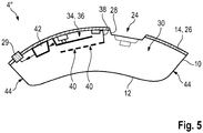
- Fig. 5 is in a longitudinal sectional view of the microphone unit 4 "after Fig. 3 shown.
- the housing 10 encloses an inner space 30.
- An ambient sound can be guided into the inner space 30 through the sound inlet opening 24 along the sound conductor 28 arranged on the second main surface 14 forming the printed circuit board 26.
- the interior 30 serves as a resonance chamber 32 for the ambient sound.
- Soldered to the printed circuit board 26 is a MEMS microphone 34, which comprises a MEMS membrane 36 which forms, in principle, a condenser microphone together with an electrode 38 soldered to the printed circuit board 26.
- the electrode 38 is provided with sound holes 40.
- the electrical signal generated at the MEMS microphone 34 is now supplied to a preliminary stage 42, which preprocesses the electrical signal, in particular by means of a preamplifier, a dynamic compressor and an AD converter, and provides the preprocessed signal via the contact electrodes 29 to the hearing aid for further processing.
- the concavely concaved first main surface 12 can in this case be produced together with the side surfaces 44 of the housing 10 in a common manufacturing process, for example by injection molding or deep drawing, which simplifies production and saves costs.
Landscapes
- Engineering & Computer Science (AREA)
- Physics & Mathematics (AREA)
- Acoustics & Sound (AREA)
- Signal Processing (AREA)
- Health & Medical Sciences (AREA)
- General Health & Medical Sciences (AREA)
- Neurosurgery (AREA)
- Otolaryngology (AREA)
- Computer Hardware Design (AREA)
- Microelectronics & Electronic Packaging (AREA)
- Details Of Audible-Bandwidth Transducers (AREA)
- Electrostatic, Electromagnetic, Magneto- Strictive, And Variable-Resistance Transducers (AREA)
Abstract
Description
- Die Erfindung betrifft eine Mikrofoneinheit mit einem Gehäuse, welches eine erste Hauptfläche und eine zweite Hauptfläche aufweist, die einander gegenüberliegen, und welches einen Innenraum umschließt, der einen Resonanzraum umfasst.
- In einem Hörgerät, insbesondere einem Hörhilfegerät, wird üblicherweise von einem Mikrofon ein Umgebungsschall in ein Audiosignal umgewandelt, welches in einer Signalverarbeitungseinheit weiter verarbeitet und dabei insbesondere frequenzbandabhängig verstärkt wird, und das hieraus resultierende Ausgangssignal von einem Lautsprecher in ein Ausgangsschallsignal umgewandelt. Das Ausgangsschallsignal wird dann dem Gehör eines Benutzers des Hörgerätes zugeführt. Je nach den audiologischen und anatomischen Anforderungen des Benutzers, und um das einzelne Hörgerät bei Tragen am Ohr für Dritte so unauffällig wie möglich auszugestallten, gibt es auf dem Markt Bauformen für Hörgeräte, bei denen wenigstens ein Teil während Tragens Gebrauchs im Gehörgangseingangstrichter oder im Gehörgang des Benutzers liegt, wie beispielsweise die ITE-Bauform, die ITC-Bauform, oder die CIC- bzw. IIC-Bauform ("in the ear", "in the canal", "completely in the canal", "invisible in the canal").
- Durch die typischen anatomischen Gegebenheiten werden hierbei den möglichen Abmessungen der einzelnen Bauformen enge Grenzen gesetzt. Dies stellt an die Entwicklung des Hörgerätes als solches sowie an die platzoptimierte Entwicklung der einzelnen Komponenten hohe Anforderungen. Im Hörgerät sind neben der eingangs genannten Komponenten Mikrofon, Signalverarbeitungseinheit, und Lautsprecher zumindest noch eine Batterie zur Leistungsversorgung sowie meist noch weitere Komponenten, beispielsweise eine Antenne zur externen Datenübertragung anzuordnen.
- In Hörgeräten werden derzeit häufig Mikrofone mit einem Mikro-Elektromechanischen System (MEMS, "micro electro mechanical system") verwendet. Bei einem derartigen MEMS-Mikrofon sind die eigentlichen signalerzeugenden Komponenten zusammen mit Elektronikkomponenten zur Vorverarbeitung des erzeugten Signals in einem Gehäuse verbaut, welches eine Schalleintrittsöffnung aufweist, und dessen Innenraum somit als Resonanzraum dient. Die Elektronikkomponenten sind dabei zusammen mit den eigentlichen signalerzeugenden Komponenten oftmals auf einer gemeinsamen Leiterplatte verlötet, welche auch eine Deckel- oder Bodenfläche des Gehäuses bildet. Bei besonders kleinen Bauformen für Hörgeräte, wie beispielsweise der IIC-Bauform werden die Abmessungen, also sowohl die Größe als auch die Form des Hörgerätes, im Wesentlichen durch die Batterie mit vorgegeben, welche, um einen ordentlichen Betrieb zu gewährleisten, nicht beliebig verkleinert werden kann. Die Anordnung eines MEMS-Mikrofons mit marktüblichen Dimensionen in der unmittelbaren Umgebung einer eben solchen Batterie lässt hierbei noch Optimierungsspielraum für die endgültige Abmessung des Hörgerätes offen.
- Der Erfindung liegt daher die Aufgabe zugrunde, eine Mikrofoneinheit anzugeben, welche möglichst platzsparend in einem Hörgerät verbaut werden kann.
- Die genannte Aufgabe wird erfindungsgemäß gelöst durch eine Mikrofoneinheit mit einem Gehäuse, welches eine erste Hauptfläche und eine zweite Hauptfläche aufweist, die einander gegenüberliegen, und einen Innenraum umschließt, der einen Resonanzraum umfasst, wobei die erste Hauptfläche eine konkave Einbuchtung zum Innenraum hin aufweist. Vorteilhafte und teils für sich erfinderische Ausgestaltungen sind Gegenstand der Unteransprüche und der nachfolgenden Beschreibung.
- Die erste Hauptfläche und die zweite Hauptfläche sind dabei bevorzugt jeweils begrenzt durch kantenartige Schnitte oder durch gegebenenfalls abgerundete Kanten, an welche sich jeweils eine Seitenfläche des Gehäuses anschließt, wobei ein Krümmungsradius einer Abrundung gegenüber der Abmessung der Hauptfläche vernachlässigbar ist. Insbesondere stellen hierbei die erste Hauptfläche und die zweite Hauptfläche die flächenmäßig größten Außenflächen des Gehäuses dar. Bevorzugt wird durch das Gehäuse der Innenraum vollständig, gegebenenfalls bis auf eine Anzahl an Schalleintrittsöffnungen, umschlossen. Der Resonanzraum wird insbesondere gebildet durch den vollständigen Innenraum abzüglich von gegebenenfalls im Innenraum verbauten Komponenten der Mikrofoneinheit, oder durch einen Teil des unverbauten Innenraumes, wenn beispielsweise der Innenraum eine entsprechende Trennwand aufweist. Bevorzugt ist im Innenraum wenigstens eine signalerzeugende Komponente angeordnet, welche dazu eingerichtet ist, eine Schalldruck- und/oder Luftdruckänderung in ein elektrisches Signal umzuwandeln. Weiter bevorzugt sind im Innenraum zusätzlich weitere Elektronikkomponenten zur Vorverarbeitung eines derart erzeugten elektrischen Signals verbaut, insbesondere zur Vorverstärkung und/oder Dynamik-Kompression und/oder Analog-Digital-Wandlung, um durch die Mikrofoneinheit ein möglichst weiterverarbeitungsfähiges Audiosignal auszugeben, welches insbesondere einen gewissen Mindest-Signalpegel erreicht.
- Die konkave Einbuchtung zum Innenraum hin kann sich über die gesamte erste Hauptfläche oder auch nur über einen vorzugsweise wesentlichen Flächenabschnitt, bevorzugt über wenigstens die Hälfte einer Flächenrichtung, erstrecken. Die konkave Einbuchtung kann hierbei auch flächenabschnittsweise eben sein, vergleichbar einem Paravent. Unter einer konkaven Einbuchtung zum Innenraum hin ist hierbei generell zu verstehen, dass eine parametrisierbare Menge an Strecken existiert, wobei für jede der Strecken die beiden Endpunkte jeweils im Bereich von einander gegenüberliegenden Enden des die konkave Einbuchtung betreffenden Flächenstückes der ersten Hauptfläche im Innenraum liegen, und die Strecke die erste Hauptfläche zwei Mal schneidet. Mit anderen Worten bedeutet dies, dass das Gehäuse durch die konkave Einbuchtung ein geringeres umschlossenes Volumen aufweist, als das Volumen, welches ein Gehäuse mit einer ersten Hauptfläche ohne jegliche konkave Einbuchtung aufweisen würde. Gegenüber einem derartigen Gehäuse, in welchem also sämtliche Strecken, deren Endpunkte im Innenraum an der ersten Hauptfläche liegen, auch durchweg im Innenraum verlaufen, "fehlt" dem erfindungsgemäßen Gehäuse mit der konkaven Einbuchtung der ersten Hauptfläche im Bereich dieser Hauptfläche ein Volumenstück.
- Die konkave Einbuchtung kann vorzugsweise in ihren Abmessungen, also insbesondere im Grad der Krümmung und in der Eindringtiefe in den Innenraum, auf die Form eines anderen Baugliedes der übergeordneten Vorrichtung abgestimmt sein, in welcher die Mikrofoneinheit zum Einbau vorgesehen ist, also insbesondere an ein Bauglied in einem Hörgerät. Hierdurch greift das Bauglied in die konkave Einbuchtung der Mikrofoneinheit ein, anstatt dass die Mikrofoneinheit in Folge der Form des Baugliedes von diesem weiter beabstandet zu verbauen wäre. Somit kann die übergeordnete Vorrichtung, also insbesondere ein Hörgerät, kompakter gebaut werden als bei einem Einbau einer vergleichbaren Mikrofoneinheit ohne die entsprechende konkave Einbuchtung.
- Günstigerweise erstreckt sich hierbei die konkave Einbuchtung zum Innenraum hin über die ganze Länge der ersten Hauptfläche. Mit anderen Worten ist somit die gesamte Hauptfläche konkav, also zum Innenraum hin gekrümmt bzw. gewölbt. Bevorzug erfolgt dabei die konkave Einbuchtung entlang der längeren Flächenseite, wenn die erste Hauptfläche eine im Wesentlichen rechteckförmige Draufsicht aufweist. Die Einbuchtung kann hierbei als eine glatte Krümmung der ersten Hauptfläche ausgebildet sein, oder aber auch einzelne ebene Flächenabschnitte umfassen. Die konkave Einbuchtung kann derart erfolgen, dass in einer Flächenrichtung jeweils Geraden in die erste Hauptfläche legbar sind, und somit entlang dieser Flächenrichtung die erste Hauptfläche weder gekrümmt noch anderweitig eingebuchtet ist. Alternativ dazu kann die konkave Einbuchtung insbesondere auch derart erfolgen, dass bezüglich jeder der Seitenflächen des Gehäuses eine Flächennormale existiert, welche die Einbuchtung zwei Mal schneidet. Ein Erstrecken der konkaven Einbuchtung über die Gesamtlänge der ersten Hauptfläche ermöglicht es, die Mikrofoneinheit vollständig, also in ihrer gesamten Abmessung, an ein anderes Bauteil der übergeordneten Vorrichtung anzupassen, wodurch ein besonders kompakter Einbau ermöglicht wird.
- Zweckmäßigerweise weist die zweite Hauptfläche eine konvexe Ausbuchtung auf. Die konvexe Ausbuchtung kann sich dabei über die gesamte zweite Hauptfläche oder auch nur über einen vorzugsweise wesentlichen Flächenabschnitt, bevorzugt über wenigstens die Hälfte einer Flächenrichtung, erstrecken. Die konkave Ausbuchtung kann hierbei auch flächenabschnittsweise eben sein, vergleichbar einem Paravent. Unter einer konvexen Ausbuchtung ist hierbei generell zu verstehen, dass eine parametrisierbare Menge an Strecken existiert, wobei für jede der Strecken die beiden Endpunkte jeweils dem Innenraum zugewandt am die konvexe Ausbuchtung betreffenden Flächenabschnitt der zweiten Hauptfläche liegen, und die Strecke vollständig durch den Innenraum verläuft. Mit anderen Worten bedeutet dies, dass das Gehäuse durch die konvexe Ausbuchtung ein größeres umschlossenes Volumen aufweist als das Volumen, welches ein Gehäuse mit einer ersten Hauptfläche ohne jegliche konvexe Ausbuchtung aufweisen würde. Gegenüber einem derartigen Gehäuse ist dem erfindungsgemäßen Gehäuse mit der konvexen Ausbuchtung der ersten Hauptfläche im Bereich dieser Hauptfläche ein nach außen, also vom Innenraum weg gewölbtes Volumenstück hinzugefügt.
- Insbesondere sind die erste Hauptfläche und die zweite Hauptfläche lokal parallel zueinander angeordnet, d.h., dass sie bezüglich der lokalen Flächennormalen einen konstanten Abstand zueinander aufweist. Dies ist beispielsweise bei einer Ausgestaltung der ersten und zweiten Hauptfläche als jeweilige Mantelabschnitte zweier koaxialer Zylinder der Fall. Eine derartige Ausgestaltung ist insbesondere von Vorteil, wenn das Bauglied, welches beim Einbau in die übergeordnete Vorrichtung in die konkave Einrichtung der Mikrofoneinheit eingreift, eine Dreh- oder Rotationssymmetrie aufweist. Alternativ dazu kann die erste Hauptfläche parallel zur zweiten Hauptfläche verschoben sein. Eine derartige Beabstandung lässt sich in der Fertigung ohne einen erheblichen Mehraufwand überwachen, was im Fertigungsprozess die Kosten begrenzt. Eine konvexe Ausbuchtung an der zweiten Hauptfläche sorgt dafür, dass zusätzlich zum Eingreifen des Baugliedes in die konkave Einbuchtung der ersten Hauptfläche die gesamte Mikrofoneinheit in ihrer Form an die Form des Bauglieds angepasst werden kann, was eine noch kompaktere Bauweise ermöglicht.
- Vorteilhafterweise umfasst die zweite Hauptfläche eine Anzahl an Schalleintrittsöffnungen. Unter einer Schalleintrittsöffnung ist dabei generell eine Öffnung zu verstehen, welche infolge ihrer Größe und Anordnung dazu geeignet ist, Schallwellen, insbesondere Schallwellen im menschlichen Hörspektrum, von außerhalb der Mikrofoneinheit in den Innenraum zu führen, sodass dabei Verfälschungseffekte wie zum Absorption oder Beugung mit Interferenzen vernachlässigbar bleiben. Bevorzug ist hierzu die oder jede Schalleintrittsöffnung als einzelne Bohrung in der zweiten Hauptfläche ausgestaltet. Hierbei kann insbesondere den Schallwellen auf dem durch die Schalleintrittsöffnung vorgegebenen Schallweg in den Innenraum des Gehäuses durch Komponenten, welche innerhalb des Gehäuses angeordnet sind, noch eine weitere Struktur aufgeprägt werden. Durch eine Schalleintrittsöffnung in der zweiten Hauptfläche kann Umgebungsschall in den Innenraum der Mikrofoneinheit gelangen, und dort mittels entsprechender signalerzeugender Komponenten in ein elektrisches Signal umgewandelt werden. Hierdurch können infolge der Schutzwirkung des Gehäuses für die signalerzeugenden Komponenten diese besonders filigran dimensioniert werden, so dass die Mikrofoneinheit besonders kompakt gebaut werden kann.
- Bevorzugt umfasst die erste Hauptfläche und/oder die zweite Hauptfläche eine Leiterplatte. Insbesondere bedeutet dies, dass die erste Hauptfläche und/oder die zweite Hauptfläche des Gehäuses durch die betreffende Leiterplatte selbst gebildet wird. Alternativ dazu kann das Gehäuse derart ausgestaltet sein, dass an einer Gehäuseinnenwand an der ersten Hauptfläche und/oder der zweiten Hauptfläche die betreffende Leiterplatte angeordnet ist. Insbesondere sind auf der bzw. auf wenigstens einer Leiterplatte signalerzeugende Komponenten zur Erzeugung eines elektrischen Signals aus lokalen Schall- bzw. Luftdruckunterschieden angeordnet, und bevorzugt mit der Leiterplatte elektrisch kontaktiert, beispielsweise durch Verlöten. Im Fall, dass die erste Hauptfläche eine Leiterplatte umfasst, verläuft diese insbesondere entlang der konvexen Ausbuchtung. Für den Fall, dass die zweite Hauptfläche eine Leiterplatte umfasst, verläuft diese insbesondere entlang der konvexen Einbuchtung zum Innenraum hin. Mit anderen Worten ist die Leiterplatte in beiden Fällen nicht über ihre gesamte Fläche eben ausgebildet, sondern allenfalls flächenabschnittsweise eben, und/oder gekrümmt. Zweckmäßig ist hierbei, wenn nur eine der beiden Hauptflächen eine Leiterplatte umfasst, da in diesem Fall die jeweils andere Hauptfläche zusammen mit den Seitenflächen des Gehäuses kostengünstig einstückig herstellbar ist, beispielsweise in einem Spritzgussverfahren oder durch Tiefziehen. Die Leiterplatte kann dabei zur Kontaktierung der Mikrofoneinheit, also insbesondere zur Ausgabe eines in der Mikrofoneinheit erzeugten Audiosignals, verwendet werden, sowie zur Kontaktierung von innerhalb des Gehäuses angeordneten elektronischen Komponenten.
- Als weiter vorteilhaft erweist es sich, wenn die Mikrofoneinheit zur Erzeugung eines elektrischen Signals aus einem Umgebungsschall ein mikro-elektro-mechanisches System (MEMS) aufweist. Mikrofrone, welche zur Signalerzeugung ein MEMS verwenden, lassen sich aufgrund der geringen Dimensionen des MEMS besonders kompakt konstruieren. Aufgrund seines filigranen Aufbaus ist ein MEMS jedoch in besonderem Maße vor Umwelteinflüssen sowie vor nicht vorgesehener mechanischer Einwirkung zu schützen. Die Anordnung innerhalb des Gehäuses sowie vorzugsweise das elektrische Kontaktieren mit einer an einer der beiden Hauptflächen angeordneten Leiterplatte, beispielsweise durch Verlöten, ist hierbei besonders vorteilhaft. Durch die vorgeschlagene konvexe Einbuchtung der ersten Hauptfläche des Gehäuses lassen sich die erwünschten Platzvorteile, wie sie bei einem Einsatz eines MEMS-Mikrofones üblicherweise erzielt werden sollen, nochmals verbessern.
- Bevorzugt ist innerhalb des Gehäuses eine Anzahl an Elektronikkomponenten betreffend die Vorverarbeitung eines Mikrofonsignals angeordnet. Insbesondere weist hierbei wenigstens eine der beiden Hauptflächen eine Leiterplatte auf, an welcher die Elektronikkomponenten kontaktiert sind. Das Mikrofonsignal wird hierbei bevorzugt durch wenigstens eine signalerzeugende Komponente generiert, welche im Innenraum angeordnet ist, wobei wenigstens eine der signalerzeugenden Komponenten bevorzugt mit einer Leiterplatte kontaktiert ist, welche an einer der beiden Hauptflächen angeordnet ist. Das Mikrofonsignal ist hierbei generell als das primäre elektrische Signal zu verstehen, welches aus den im Innenraum des Gehäuses bestehenden Schalldruck- bzw. Luftdruck-Unterschieden durch eine signalerzeugende Komponente unmittelbar generiert wird. Dies kann beispielsweise über ein MEMS erfolgen. Da nicht zuletzt infolge der geringen Dimensionierung die Amplitude des Mikrofonsignals sehr gering ist, bedarf es typischerweise für eine Nutzung des Mikrofonsignals außerhalb der Mikrofoneinheit im Rahmen der Anwendung in einer übergeordneten Vorrichtung, wie beispielsweise in einem Hörgerät, einer oftmals nicht unerheblichen Vorverarbeitung des Mikrofonsignals, beispielsweise durch eine Verstärkung und/oder eine Kompression der Signaldynamik. Hierbei ist es von Vorteil, die zur Vorverarbeitung verwendeten Elektronikkomponenten mit den eigentlichen signalerzeugenden Komponenten in der Mikrofoneinheit zusammen zu fassen, so dass die Mikrofoneinheit ein im Rahmen der übergeordneten Vorrichtung weiterverarbeitungsfähiges Audiosignal ausgibt. Durch die Anordnung der Elektronikkomponenten innerhalb des den Resonanzraum umfassenden Gehäuses sind diese vor äußeren Einflüssen geschützt.
- Die Erfindung nennt weiter ein Hörgerät, umfassend eine im Wesentlichen zylinderförmige Batterie und eine Mikrofoneinheit der vorbeschriebenen Art, wobei die konkave Einbuchtung in der ersten Hauptfläche der Mikrofoneinheit derart an den Radius der Batterie angepasst ist, dass die Mikrofoneinheit entlang eines Abschnitts der Mantelfläche der Batterie angeordnet ist. Die für die Mikrofoneinheit sowie für ihre Weiterbildungen angegebenen Vorteile können dabei sinngemäß auf das Hörgerät übertragen werden. Die Batterie kann dabei insbesondere mit weiteren Komponenten, wie beispielweise einem Spannungswandler, zu einer Batterieeinheit zusammengefasst sein, um eine von der Batterie ausgegebene Versorgungsspannung auf eine Betriebsspannung des Hörgerätes zu konvertieren, wobei die zusätzlichen Komponenten der Batterieeinheit insbesondere an den Stirnflächen der Batterie angeordnet sind, so dass auch für die Batterieeinheit die im Wesentlichen zylindrische Form, welche durch die Batterie vorgegeben wird, erhalten bleibt.
- Nachfolgend wird ein Ausführungsbeispiel der Erfindung anhand einer Zeichnung näher erläutert. Hierbei zeigen jeweils schematisch:
- Fig. 1
- in einer Draufsicht ein Hörgerät mit einer Batterieeinheit und einer Mikrofoneinheit nach Stand der Technik,
- Fig. 2
- in einer Draufsicht ein Hörgerät mit einer Batterie und einer Mikrofoneinheit, deren Hauptflächen entlang der Batterie gekrümmt sind,
- Fig. 3
- in einer Schnittdarstellung ein Hörgerät mit alternativen Ausgestaltung einer gekrümmten Mikrofoneinheit,
- Fig. 4
- in einer Schrägansicht die Mikrofoneinheit nach
Fig. 3 , und - Fig. 5
- in einer Längsschnittdarstellung die Mikrofoneinheit nach
Fig. 3 . - Einander entsprechende Teile und Größen sind in allen Figuren jeweils mit gleichen Bezugszeichen versehen.
- In
Fig. 1 ist schematisch in einer Draufsicht ein Hörgerät 1 dargestellt, welches eine Batterie 2 und eine Mikrofoneinheit 4 gemäß Stand der Technik umfasst. Das Hörgerät 1 umfasst hierbei ein Außengehäuse 6, welches zur besseren Anschaulichkeit nur teilweise eingezeichnet ist. In das Außengehäuse 6 sind Klammern 8 zur Befestigung der Batterie 2 eingearbeitet. Im Außengehäuse 6 ist weiter die Mikrofoneinheit 4 angeordnet, welche im Betrieb des Hörgerätes 1 aus einem Umgebungsschall ein Mikrofonsignal erzeugt, welches im Hörgerät 1 benutzerspezifisch weiterverarbeitet wird. Infolge der zylindrischen Form der Batterie 2 kann die Mikrofoneinheit 4 nicht beliebig kompakt an die Batterie 2 angebaut werden, wodurch das Außengehäuse 6 vergrößer wird, und im Innenraum des Hörgerätes 1 schwer ausnutzbare Leerräume 9 gebildet werden. Auch eine tangential zur Batterie 2 verkippte Anordnung der Mikrofoneinheit 4 würde hieran im Wesentlichen nicht viel ändern, und nur für einen durch die Verkippung und hiermit erschwerte Befestigung der Mikrofoneinheit 4 erhöhten Konstruktionsaufwand führen. - In
Fig. 2 ist schematisch in einer Draufsicht ein Hörgerät 1' mit einer Batterie 2 und einer Mikrofoneinheit 4' dargestellt, welche teilweise an die Form der Batterie 2 angepasst ist. Erneut ist zur besseren Anschaulichkeit nur ein Teil des Außengehäuses 6' des Hörgerätes 1' gezeigt. Die Mikrofoneinheit 4' weist ein Gehäuse 10 mit einer ersten Hauptfläche 12 und einer der ersten Hauptfläche 12 gegenüber liegenden zweiten Hauptfläche 14 auf, wobei die erste Hauptfläche 12 konkav zum Inneren der Mikrofoneinheit 4' hin eingebuchtet ist, und die zweite Hauptfläche 14 konvex nach außen ausgebuchtet ist. In die so ausgebildete konkave Einbuchtung 16 der ersten Hauptfläche kann nun die Batterie 2 derart eingreifen, dass die Mikrofoneinheit 4' im Bereich der Klammer 8 entlang eines Abschnittes 18 der Mantelfläche 20 der Batterie 2 angeordnet werden kann. - In
Fig. 3 ist schematisch in einer Schnittdarstellung ein Hörgerät 1" mit einer zur inFigur 2 dargestellten Ausgestaltung alternativen Variante einer Mikrofoneinheit 4" gezeigt. Hier wird die Mikrofoneinheit 4" nicht im Bereich einer der Klammern 8, sondern direkt an der Batterie 2 angeordnet, wobei durch die konkave Einbuchtung 16 der ersten Hauptfläche 12 der Mikrofoneinheit 4" letztere für den Abschnitt 18 entlang der Mantelfläche 20 verläuft. Die Krümmung der konkaven Einbuchtung 16 ist dabei an den Radius der Batterie 2 angepasst. Die zweite Hauptfläche 14 der Mikrofoneinheit 4" weist eine der konkaven Einbuchtung 16 der ersten Hauptfläche 12 entsprechende konvexe Ausbuchtung 22 auf, welche ebenfalls an den Radius der Batterie 2 angepasst ist. - In
Fig. 4 ist in einer Schrägansicht die Mikrofoneinheit 4" nachFig. 3 dargestellt. Die Mikrofoneinheit 4" wird umschlossen von einem Gehäuse 10 mit einer ersten Hauptfläche 12 und einer der ersten Hauptfläche 12 gegenüber liegenden zweiten Hauptfläche 14. Die erste Hauptfläche 12 bildet zum des vom Gehäuse 10 umschlossenen Innenraumes hin eine konkave Einbuchtung 16 aus, die zweite Hauptfläche 14 bildet eine der konkaven Einbuchtung 16 entsprechende konvexe Ausbuchtung 22 aus. In der zweiten Hauptfläche 14 ist eine Schalleintrittsöffnung 24 eingebracht, durch welche ein Umgebungsschall in den vom Gehäuse 10 umschlossenen Innenraum gelangen kann, wo aus dem Umgebungsschall durch inFig. 4 nicht näher dargestellte signalerzeugende Komponenten ein elektrisches Signal erzeugt wird. Die zweite Hauptfläche 14 wird hierbei gebildet durch eine Leiterplatte 26, welche mit der Schalleintrittsöffnung 24 versehen ist. Zur besseren Schallführung in den Innenraum der Mikrofoneinheit 4" und zur Vermeidung von Beugungen und Interferenzen ist an der Schalleintrittsöffnung 24 zum Innenraum hin ein Schalltrichter 28 auf der Leiterplatte 26 angeordnet. Weiter sind an der Leiterplatte 26 Kontaktelektroden 29 angeordnet, über welche die Mikrofoneinheit 10 an das Hörgerät 1" ein Mikrofonsignal ausgibt, sowie ggf. zur Leistungsversorgung aktiver Komponenten in der Mikrofoneinheit 10. - In
Fig. 5 ist in einer Längsschnittdarstellung die Mikrofoneinheit 4" nachFig. 3 gezeigt. Das Gehäuse 10 umschließt einen Innenraum 30. Durch die Schalleintrittsöffnung 24 kann entlang des auf der die zweite Hauptfläche 14 bildenden Leiterplatte 26 angeordneten Schalltrichters 28 ein Umgebungsschall in den Innenraum 30 geführt werden. Der Innenraum 30 dient dabei als Resonanzraum 32 für den Umgebungsschall. Mit der Leiterplatte 26 verlötet ist ein MEMS-Mikrofon 34, welches eine MEMS-Membran 36 umfasst, die zusammen mit einer auf der Leiterplatte 26 verlöteten Elektrode 38 dem Prinzip nach ein Kondensatormikrofon bildet. Zur besseren Schalldurchlässigkeit hinsichtlich des Resonanzraumes 32 ist die Elektrode 38 mit Schalllöchern 40 versehen. Das am MEMS-Mikrofon 34 erzeugte elektrische Signal wird nun einer Vorstufe 42 zugeführt, welche das elektrische Signal insbesondere mittels eines Vorverstärkers, eines Dynamik-Kompressors und eines A-D-Wandlers vorverarbeitet, und das vorverarbeitete Signal über die Kontaktelektroden 29 dem Hörgerät zur Weiterverarbeitung bereitstellt. Die konkav eingebuchtete erste Hauptfläche 12 kann hierbei zusammen mit den Seitenflächen 44 des Gehäuses 10 in einem gemeinsamen Fertigungsprozess, beispielsweise durch Spritzgießen oder Tiefenziehen, hergestellt werden, was die Produktion vereinfacht und Kosten spart. - Obwohl die Erfindung im Detail durch das bevorzugte Ausführungsbeispiel näher illustriert und beschrieben wurde, ist die Erfindung nicht durch dieses Ausführungsbeispiel eingeschränkt. Andere Variationen können vom Fachmann hieraus abgeleitet werden, ohne den Schutzumfang der Erfindung zu verlassen.
-
- 1
- Hörgerät
- 1', 1"
- Hörgerät
- 2
- Batterie
- 4
- Mikrofoneinheit (nach Stand der Technik)
- 4', 4"
- Mikrofoneinheit
- 6
- Außengehäuse
- 6', 6"
- Außengehäuse
- 8
- Klammer
- 9
- Leerräume
- 10
- Gehäuse
- 12
- erste Hauptfläche
- 14
- zweite Hauptfläche
- 16
- konkave Einbuchtung
- 18
- Abschnitt
- 20
- Mantelfläche
- 22
- konvexe Ausbuchtung
- 24
- Schalleintrittsöffnung
- 26
- Leiterplatte
- 28
- Schalltrichter
- 29
- Kontaktelektrode
- 30
- Innenraum
- 32
- Resonanzraum
- 34
- MEMS-Mikrofon
- 36
- MEMS-Membran
- 38
- Elektrode
- 40
- Schalllöcher
- 42
- Vorstufe
- 44
- Seitenflächen
Claims (8)
- Mikrofoneinheit (4', 4") mit einem Gehäuse (10), welches- eine erste Hauptfläche (12) und eine zweite Hauptfläche (14) aufweist, die einander gegenüberliegen, und- einen Innenraum umschließt, der einen Resonanzraum umfasst, wobei die erste Hauptfläche (12) eine konkave Einbuchtung (16) zum Innenraum (30) hin aufweist.
- Mikrofoneinheit (4', 4") nach Anspruch 1,
wobei die konkave Einbuchtung (16) zum Innenraum (30) hin sich über die ganze Länge der ersten Hauptfläche (12) erstreckt. - Mikrofoneinheit (4', 4") nach Anspruch 1 oder Anspruch 2,
wobei die zweite Hauptfläche (14) eine konvexe Ausbuchtung (22) aufweist. - Mikrofoneinheit (4', 4") nach einem der vorhergehenden Ansprüche,
wobei die zweite Hauptfläche (14) eine Anzahl an Schalleintrittsöffnungen (24) umfasst. - Mikrofoneinheit (4', 4") nach einem der vorhergehenden Ansprüche,
wobei die erste Hauptfläche (12) und/oder zweite Hauptfläche (14) eine Leiterplatte (26) umfasst. - Mikrofoneinheit (4', 4") nach einem der vorhergehenden Ansprüche,
welche zur Erzeugung eines Mikrofonsignals aus einem Umgebungsschall ein Mikro-elektro-mechanisches System (34, 36) aufweist. - Mikrofoneinheit (4', 4") nach einem der vorhergehenden Ansprüche,
wobei innerhalb des Gehäuses (10) eine Anzahl an Elektronikkomponenten (42) betreffend die Vorverarbeitung eines Mikrofonsignals angeordnet ist. - Hörgerät (1'), umfassend eine im Wesentlichen zylinderförmige Batterie (2) und eine Mikrofoneinheit (4', 4") nach einem der vorhergehenden Ansprüche, wobei die konkave Einbuchtung (16) in der ersten Hauptfläche (12) der Mikrofoneinheit (4', 4") derart an den Radius der Batterie (2) angepasst ist, dass die Mikrofoneinheit (4', 4") entlang eines Abschnitts (18) der Mantelfläche (20) der Batterie (2) angeordnet ist.
Applications Claiming Priority (1)
| Application Number | Priority Date | Filing Date | Title |
|---|---|---|---|
| DE102017201465.2A DE102017201465B4 (de) | 2017-01-30 | 2017-01-30 | Mikrofoneinheit mit einem Gehäuse |
Publications (2)
| Publication Number | Publication Date |
|---|---|
| EP3355591A1 true EP3355591A1 (de) | 2018-08-01 |
| EP3355591B1 EP3355591B1 (de) | 2019-12-04 |
Family
ID=60673632
Family Applications (1)
| Application Number | Title | Priority Date | Filing Date |
|---|---|---|---|
| EP17207541.8A Active EP3355591B1 (de) | 2017-01-30 | 2017-12-15 | Hörgerät umfassend eine mikrofoneinheit mit einem gehäuse |
Country Status (5)
| Country | Link |
|---|---|
| US (1) | US10506352B2 (de) |
| EP (1) | EP3355591B1 (de) |
| CN (1) | CN108377452B (de) |
| DE (1) | DE102017201465B4 (de) |
| DK (1) | DK3355591T3 (de) |
Cited By (1)
| Publication number | Priority date | Publication date | Assignee | Title |
|---|---|---|---|---|
| CN111556419A (zh) * | 2020-05-27 | 2020-08-18 | 潍坊歌尔微电子有限公司 | 骨声纹传感器和电子设备 |
Families Citing this family (1)
| Publication number | Priority date | Publication date | Assignee | Title |
|---|---|---|---|---|
| CN113132879B (zh) * | 2019-12-30 | 2023-06-30 | 美商楼氏电子有限公司 | 用于麦克风组件的声音端口适配器 |
Citations (2)
| Publication number | Priority date | Publication date | Assignee | Title |
|---|---|---|---|---|
| US7254247B2 (en) * | 2001-12-07 | 2007-08-07 | Oticon A/S | Hearing aid with a microphone in the battery compartment lid |
| US20090161886A1 (en) * | 2007-11-30 | 2009-06-25 | Funai Electric Co., Ltd. | Microphone unit and sound input apparatus |
Family Cites Families (5)
| Publication number | Priority date | Publication date | Assignee | Title |
|---|---|---|---|---|
| US6097825A (en) * | 1996-09-19 | 2000-08-01 | Beltone Electronics Corporation | Hearing aids with standardized spheroidal housings |
| DE29916871U1 (de) | 1999-09-24 | 2001-02-08 | Peiker, Andreas, 61381 Friedrichsdorf | Mikrofongehäuse |
| KR100982239B1 (ko) | 2007-11-02 | 2010-09-14 | 주식회사 비에스이 | 피시비에 음공이 형성된 멤스 마이크로폰 패키지 |
| US8515113B2 (en) | 2010-08-19 | 2013-08-20 | Apple Inc. | Composite microphone boot to optimize sealing and mechanical properties |
| DE102015203536B4 (de) * | 2015-02-27 | 2019-08-29 | Sivantos Pte. Ltd. | Mobiler kontaktloser Ladeadapter |
-
2017
- 2017-01-30 DE DE102017201465.2A patent/DE102017201465B4/de active Active
- 2017-12-15 EP EP17207541.8A patent/EP3355591B1/de active Active
- 2017-12-15 DK DK17207541.8T patent/DK3355591T3/da active
-
2018
- 2018-01-03 CN CN201810004061.3A patent/CN108377452B/zh not_active Expired - Fee Related
- 2018-01-26 US US15/881,254 patent/US10506352B2/en active Active
Patent Citations (2)
| Publication number | Priority date | Publication date | Assignee | Title |
|---|---|---|---|---|
| US7254247B2 (en) * | 2001-12-07 | 2007-08-07 | Oticon A/S | Hearing aid with a microphone in the battery compartment lid |
| US20090161886A1 (en) * | 2007-11-30 | 2009-06-25 | Funai Electric Co., Ltd. | Microphone unit and sound input apparatus |
Cited By (1)
| Publication number | Priority date | Publication date | Assignee | Title |
|---|---|---|---|---|
| CN111556419A (zh) * | 2020-05-27 | 2020-08-18 | 潍坊歌尔微电子有限公司 | 骨声纹传感器和电子设备 |
Also Published As
| Publication number | Publication date |
|---|---|
| DE102017201465B4 (de) | 2021-10-21 |
| US10506352B2 (en) | 2019-12-10 |
| DK3355591T3 (da) | 2020-02-24 |
| CN108377452A (zh) | 2018-08-07 |
| EP3355591B1 (de) | 2019-12-04 |
| CN108377452B (zh) | 2021-03-05 |
| US20180220244A1 (en) | 2018-08-02 |
| DE102017201465A1 (de) | 2018-08-02 |
Similar Documents
| Publication | Publication Date | Title |
|---|---|---|
| EP2534855B1 (de) | Hinter-dem-ohr-hörgerät mit steckverbinder | |
| EP2334102A2 (de) | Hörgerät mit einer platzsparenden Anordnung von Mikrofonen und Schallöffnungen | |
| DE112007000845T5 (de) | Wandlermonitorsystem und Herstellverfahren für dieses | |
| EP2219392B1 (de) | Microfonmodul für eine hörvorrichtung | |
| DE60204241T2 (de) | Verfahren zur herstellung eines hörgeräts | |
| CH664057A5 (de) | Hoergeraet. | |
| EP2701404B1 (de) | Hörinstrument und Ohrstück mit Receiver | |
| EP3799440A1 (de) | Schallwandlereinheit zum erzeugen und/oder erfassen von schallwellen im hörbaren wellenlängenbereich und/oder im ultraschallbereich | |
| EP2180724A1 (de) | Ohrstück mit Stegen | |
| EP1903835A2 (de) | Hörer mit zusätzlicher Abschirmeinrichtung | |
| DE102010015400B4 (de) | Mikrofon für eine Hörvorrichtung sowie Verfahren zum Ermitteln eines Luftschalls und eines Körperschalls | |
| DE102016222323A1 (de) | Hörhilfegerät mit Elektronikrahmen und darin integrierter Antenne | |
| EP3355591B1 (de) | Hörgerät umfassend eine mikrofoneinheit mit einem gehäuse | |
| EP3481084A1 (de) | Hörgerät | |
| DE10131214C1 (de) | Mikrofonanordnung in einem hinter dem Ohr tragbaren Hörgerät | |
| DE10334396B3 (de) | Hörhilfegerät sowie Verfahren zum Betrieb eines Hörhilfegerätes mit einem Mikrofonsystem, bei dem unterschiedliche Richtcharakteristiken einstellbar sind | |
| EP0489023B1 (de) | Im-ohr-hörgerät mit schall-ausgleichskanal | |
| DE102013207080B4 (de) | Binaurale Mikrofonanpassung mittels der eigenen Stimme | |
| DE102008052682B4 (de) | Hörereinrichtung mit beweglichem Hörer | |
| WO2007051606A1 (de) | Wandlersystem für eine aktive lärmkompensationsvorrichtung | |
| DE102017210448B3 (de) | Hörgerät | |
| DE102004044318B3 (de) | Schlauchförmige Verbindungsleitung für ein Hörgerät und Hörgerät | |
| DE102011006417B3 (de) | Hörvorrichtung mit Haarschutzeinrichtung | |
| DE102007003248A1 (de) | Hörgerät | |
| EP2018078A2 (de) | Hörvorrichtung mit einer Befestigungseinrichtung zum Anstecken eines Audioschuhs und entsprechender Audioschuh |
Legal Events
| Date | Code | Title | Description |
|---|---|---|---|
| PUAI | Public reference made under article 153(3) epc to a published international application that has entered the european phase |
Free format text: ORIGINAL CODE: 0009012 |
|
| STAA | Information on the status of an ep patent application or granted ep patent |
Free format text: STATUS: THE APPLICATION HAS BEEN PUBLISHED |
|
| AK | Designated contracting states |
Kind code of ref document: A1 Designated state(s): AL AT BE BG CH CY CZ DE DK EE ES FI FR GB GR HR HU IE IS IT LI LT LU LV MC MK MT NL NO PL PT RO RS SE SI SK SM TR |
|
| AX | Request for extension of the european patent |
Extension state: BA ME |
|
| STAA | Information on the status of an ep patent application or granted ep patent |
Free format text: STATUS: REQUEST FOR EXAMINATION WAS MADE |
|
| 17P | Request for examination filed |
Effective date: 20190122 |
|
| RBV | Designated contracting states (corrected) |
Designated state(s): AL AT BE BG CH CY CZ DE DK EE ES FI FR GB GR HR HU IE IS IT LI LT LU LV MC MK MT NL NO PL PT RO RS SE SI SK SM TR |
|
| GRAP | Despatch of communication of intention to grant a patent |
Free format text: ORIGINAL CODE: EPIDOSNIGR1 |
|
| STAA | Information on the status of an ep patent application or granted ep patent |
Free format text: STATUS: GRANT OF PATENT IS INTENDED |
|
| INTG | Intention to grant announced |
Effective date: 20190628 |
|
| GRAS | Grant fee paid |
Free format text: ORIGINAL CODE: EPIDOSNIGR3 |
|
| GRAA | (expected) grant |
Free format text: ORIGINAL CODE: 0009210 |
|
| STAA | Information on the status of an ep patent application or granted ep patent |
Free format text: STATUS: THE PATENT HAS BEEN GRANTED |
|
| AK | Designated contracting states |
Kind code of ref document: B1 Designated state(s): AL AT BE BG CH CY CZ DE DK EE ES FI FR GB GR HR HU IE IS IT LI LT LU LV MC MK MT NL NO PL PT RO RS SE SI SK SM TR |
|
| REG | Reference to a national code |
Ref country code: GB Ref legal event code: FG4D Free format text: NOT ENGLISH |
|
| REG | Reference to a national code |
Ref country code: CH Ref legal event code: EP Ref country code: CH Ref legal event code: NV Representative=s name: E. BLUM AND CO. AG PATENT- UND MARKENANWAELTE , CH |
|
| REG | Reference to a national code |
Ref country code: AT Ref legal event code: REF Ref document number: 1211027 Country of ref document: AT Kind code of ref document: T Effective date: 20191215 |
|
| REG | Reference to a national code |
Ref country code: DE Ref legal event code: R096 Ref document number: 502017003047 Country of ref document: DE |
|
| REG | Reference to a national code |
Ref country code: IE Ref legal event code: FG4D Free format text: LANGUAGE OF EP DOCUMENT: GERMAN |
|
| REG | Reference to a national code |
Ref country code: DK Ref legal event code: T3 Effective date: 20200217 |
|
| REG | Reference to a national code |
Ref country code: NL Ref legal event code: MP Effective date: 20191204 |
|
| REG | Reference to a national code |
Ref country code: LT Ref legal event code: MG4D |
|
| PG25 | Lapsed in a contracting state [announced via postgrant information from national office to epo] |
Ref country code: FI Free format text: LAPSE BECAUSE OF FAILURE TO SUBMIT A TRANSLATION OF THE DESCRIPTION OR TO PAY THE FEE WITHIN THE PRESCRIBED TIME-LIMIT Effective date: 20191204 Ref country code: BG Free format text: LAPSE BECAUSE OF FAILURE TO SUBMIT A TRANSLATION OF THE DESCRIPTION OR TO PAY THE FEE WITHIN THE PRESCRIBED TIME-LIMIT Effective date: 20200304 Ref country code: LT Free format text: LAPSE BECAUSE OF FAILURE TO SUBMIT A TRANSLATION OF THE DESCRIPTION OR TO PAY THE FEE WITHIN THE PRESCRIBED TIME-LIMIT Effective date: 20191204 Ref country code: GR Free format text: LAPSE BECAUSE OF FAILURE TO SUBMIT A TRANSLATION OF THE DESCRIPTION OR TO PAY THE FEE WITHIN THE PRESCRIBED TIME-LIMIT Effective date: 20200305 Ref country code: NO Free format text: LAPSE BECAUSE OF FAILURE TO SUBMIT A TRANSLATION OF THE DESCRIPTION OR TO PAY THE FEE WITHIN THE PRESCRIBED TIME-LIMIT Effective date: 20200304 Ref country code: SE Free format text: LAPSE BECAUSE OF FAILURE TO SUBMIT A TRANSLATION OF THE DESCRIPTION OR TO PAY THE FEE WITHIN THE PRESCRIBED TIME-LIMIT Effective date: 20191204 Ref country code: LV Free format text: LAPSE BECAUSE OF FAILURE TO SUBMIT A TRANSLATION OF THE DESCRIPTION OR TO PAY THE FEE WITHIN THE PRESCRIBED TIME-LIMIT Effective date: 20191204 |
|
| PG25 | Lapsed in a contracting state [announced via postgrant information from national office to epo] |
Ref country code: RS Free format text: LAPSE BECAUSE OF FAILURE TO SUBMIT A TRANSLATION OF THE DESCRIPTION OR TO PAY THE FEE WITHIN THE PRESCRIBED TIME-LIMIT Effective date: 20191204 Ref country code: HR Free format text: LAPSE BECAUSE OF FAILURE TO SUBMIT A TRANSLATION OF THE DESCRIPTION OR TO PAY THE FEE WITHIN THE PRESCRIBED TIME-LIMIT Effective date: 20191204 |
|
| PG25 | Lapsed in a contracting state [announced via postgrant information from national office to epo] |
Ref country code: AL Free format text: LAPSE BECAUSE OF FAILURE TO SUBMIT A TRANSLATION OF THE DESCRIPTION OR TO PAY THE FEE WITHIN THE PRESCRIBED TIME-LIMIT Effective date: 20191204 |
|
| PG25 | Lapsed in a contracting state [announced via postgrant information from national office to epo] |
Ref country code: ES Free format text: LAPSE BECAUSE OF FAILURE TO SUBMIT A TRANSLATION OF THE DESCRIPTION OR TO PAY THE FEE WITHIN THE PRESCRIBED TIME-LIMIT Effective date: 20191204 Ref country code: NL Free format text: LAPSE BECAUSE OF FAILURE TO SUBMIT A TRANSLATION OF THE DESCRIPTION OR TO PAY THE FEE WITHIN THE PRESCRIBED TIME-LIMIT Effective date: 20191204 Ref country code: RO Free format text: LAPSE BECAUSE OF FAILURE TO SUBMIT A TRANSLATION OF THE DESCRIPTION OR TO PAY THE FEE WITHIN THE PRESCRIBED TIME-LIMIT Effective date: 20191204 Ref country code: CZ Free format text: LAPSE BECAUSE OF FAILURE TO SUBMIT A TRANSLATION OF THE DESCRIPTION OR TO PAY THE FEE WITHIN THE PRESCRIBED TIME-LIMIT Effective date: 20191204 Ref country code: PT Free format text: LAPSE BECAUSE OF FAILURE TO SUBMIT A TRANSLATION OF THE DESCRIPTION OR TO PAY THE FEE WITHIN THE PRESCRIBED TIME-LIMIT Effective date: 20200429 Ref country code: EE Free format text: LAPSE BECAUSE OF FAILURE TO SUBMIT A TRANSLATION OF THE DESCRIPTION OR TO PAY THE FEE WITHIN THE PRESCRIBED TIME-LIMIT Effective date: 20191204 |
|
| REG | Reference to a national code |
Ref country code: BE Ref legal event code: MM Effective date: 20191231 |
|
| PG25 | Lapsed in a contracting state [announced via postgrant information from national office to epo] |
Ref country code: SK Free format text: LAPSE BECAUSE OF FAILURE TO SUBMIT A TRANSLATION OF THE DESCRIPTION OR TO PAY THE FEE WITHIN THE PRESCRIBED TIME-LIMIT Effective date: 20191204 Ref country code: IS Free format text: LAPSE BECAUSE OF FAILURE TO SUBMIT A TRANSLATION OF THE DESCRIPTION OR TO PAY THE FEE WITHIN THE PRESCRIBED TIME-LIMIT Effective date: 20200404 Ref country code: SM Free format text: LAPSE BECAUSE OF FAILURE TO SUBMIT A TRANSLATION OF THE DESCRIPTION OR TO PAY THE FEE WITHIN THE PRESCRIBED TIME-LIMIT Effective date: 20191204 |
|
| REG | Reference to a national code |
Ref country code: DE Ref legal event code: R097 Ref document number: 502017003047 Country of ref document: DE |
|
| PG25 | Lapsed in a contracting state [announced via postgrant information from national office to epo] |
Ref country code: MC Free format text: LAPSE BECAUSE OF FAILURE TO SUBMIT A TRANSLATION OF THE DESCRIPTION OR TO PAY THE FEE WITHIN THE PRESCRIBED TIME-LIMIT Effective date: 20191204 |
|
| PLBE | No opposition filed within time limit |
Free format text: ORIGINAL CODE: 0009261 |
|
| STAA | Information on the status of an ep patent application or granted ep patent |
Free format text: STATUS: NO OPPOSITION FILED WITHIN TIME LIMIT |
|
| PG25 | Lapsed in a contracting state [announced via postgrant information from national office to epo] |
Ref country code: LU Free format text: LAPSE BECAUSE OF NON-PAYMENT OF DUE FEES Effective date: 20191215 Ref country code: IE Free format text: LAPSE BECAUSE OF NON-PAYMENT OF DUE FEES Effective date: 20191215 |
|
| 26N | No opposition filed |
Effective date: 20200907 |
|
| PG25 | Lapsed in a contracting state [announced via postgrant information from national office to epo] |
Ref country code: BE Free format text: LAPSE BECAUSE OF NON-PAYMENT OF DUE FEES Effective date: 20191231 Ref country code: PL Free format text: LAPSE BECAUSE OF FAILURE TO SUBMIT A TRANSLATION OF THE DESCRIPTION OR TO PAY THE FEE WITHIN THE PRESCRIBED TIME-LIMIT Effective date: 20191204 Ref country code: SI Free format text: LAPSE BECAUSE OF FAILURE TO SUBMIT A TRANSLATION OF THE DESCRIPTION OR TO PAY THE FEE WITHIN THE PRESCRIBED TIME-LIMIT Effective date: 20191204 |
|
| PG25 | Lapsed in a contracting state [announced via postgrant information from national office to epo] |
Ref country code: IT Free format text: LAPSE BECAUSE OF FAILURE TO SUBMIT A TRANSLATION OF THE DESCRIPTION OR TO PAY THE FEE WITHIN THE PRESCRIBED TIME-LIMIT Effective date: 20191204 |
|
| PG25 | Lapsed in a contracting state [announced via postgrant information from national office to epo] |
Ref country code: CY Free format text: LAPSE BECAUSE OF FAILURE TO SUBMIT A TRANSLATION OF THE DESCRIPTION OR TO PAY THE FEE WITHIN THE PRESCRIBED TIME-LIMIT Effective date: 20191204 |
|
| PG25 | Lapsed in a contracting state [announced via postgrant information from national office to epo] |
Ref country code: HU Free format text: LAPSE BECAUSE OF FAILURE TO SUBMIT A TRANSLATION OF THE DESCRIPTION OR TO PAY THE FEE WITHIN THE PRESCRIBED TIME-LIMIT; INVALID AB INITIO Effective date: 20171215 Ref country code: MT Free format text: LAPSE BECAUSE OF FAILURE TO SUBMIT A TRANSLATION OF THE DESCRIPTION OR TO PAY THE FEE WITHIN THE PRESCRIBED TIME-LIMIT Effective date: 20191204 |
|
| PG25 | Lapsed in a contracting state [announced via postgrant information from national office to epo] |
Ref country code: TR Free format text: LAPSE BECAUSE OF FAILURE TO SUBMIT A TRANSLATION OF THE DESCRIPTION OR TO PAY THE FEE WITHIN THE PRESCRIBED TIME-LIMIT Effective date: 20191204 |
|
| PG25 | Lapsed in a contracting state [announced via postgrant information from national office to epo] |
Ref country code: MK Free format text: LAPSE BECAUSE OF FAILURE TO SUBMIT A TRANSLATION OF THE DESCRIPTION OR TO PAY THE FEE WITHIN THE PRESCRIBED TIME-LIMIT Effective date: 20191204 |
|
| REG | Reference to a national code |
Ref country code: AT Ref legal event code: MM01 Ref document number: 1211027 Country of ref document: AT Kind code of ref document: T Effective date: 20221215 |
|
| PG25 | Lapsed in a contracting state [announced via postgrant information from national office to epo] |
Ref country code: AT Free format text: LAPSE BECAUSE OF NON-PAYMENT OF DUE FEES Effective date: 20221215 |
|
| PG25 | Lapsed in a contracting state [announced via postgrant information from national office to epo] |
Ref country code: AT Free format text: LAPSE BECAUSE OF NON-PAYMENT OF DUE FEES Effective date: 20221215 |
|
| REG | Reference to a national code |
Ref country code: CH Ref legal event code: U11 Free format text: ST27 STATUS EVENT CODE: U-0-0-U10-U11 (AS PROVIDED BY THE NATIONAL OFFICE) Effective date: 20260101 |
|
| PGFP | Annual fee paid to national office [announced via postgrant information from national office to epo] |
Ref country code: DE Payment date: 20251126 Year of fee payment: 9 |
|
| PGFP | Annual fee paid to national office [announced via postgrant information from national office to epo] |
Ref country code: GB Payment date: 20251119 Year of fee payment: 9 |
|
| PGFP | Annual fee paid to national office [announced via postgrant information from national office to epo] |
Ref country code: DK Payment date: 20251119 Year of fee payment: 9 |
|
| PGFP | Annual fee paid to national office [announced via postgrant information from national office to epo] |
Ref country code: FR Payment date: 20251120 Year of fee payment: 9 |
|
| PGFP | Annual fee paid to national office [announced via postgrant information from national office to epo] |
Ref country code: AT Payment date: 20260410 Year of fee payment: 5 |
|
| PGFP | Annual fee paid to national office [announced via postgrant information from national office to epo] |
Ref country code: CH Payment date: 20260101 Year of fee payment: 9 |