EP3355552B1 - Verfahren und vorrichtung zur steuerung einer elektronischen vorrichtung - Google Patents
Verfahren und vorrichtung zur steuerung einer elektronischen vorrichtung Download PDFInfo
- Publication number
- EP3355552B1 EP3355552B1 EP16879399.0A EP16879399A EP3355552B1 EP 3355552 B1 EP3355552 B1 EP 3355552B1 EP 16879399 A EP16879399 A EP 16879399A EP 3355552 B1 EP3355552 B1 EP 3355552B1
- Authority
- EP
- European Patent Office
- Prior art keywords
- control
- user
- information
- control mode
- electronic devices
- Prior art date
- Legal status (The legal status is an assumption and is not a legal conclusion. Google has not performed a legal analysis and makes no representation as to the accuracy of the status listed.)
- Active
Links
Images


Classifications
-
- H—ELECTRICITY
- H04—ELECTRIC COMMUNICATION TECHNIQUE
- H04L—TRANSMISSION OF DIGITAL INFORMATION, e.g. TELEGRAPHIC COMMUNICATION
- H04L67/00—Network arrangements or protocols for supporting network services or applications
- H04L67/01—Protocols
- H04L67/12—Protocols specially adapted for proprietary or special-purpose networking environments, e.g. medical networks, sensor networks, networks in vehicles or remote metering networks
- H04L67/125—Protocols specially adapted for proprietary or special-purpose networking environments, e.g. medical networks, sensor networks, networks in vehicles or remote metering networks involving control of end-device applications over a network
-
- G—PHYSICS
- G06—COMPUTING OR CALCULATING; COUNTING
- G06F—ELECTRIC DIGITAL DATA PROCESSING
- G06F3/00—Input arrangements for transferring data to be processed into a form capable of being handled by the computer; Output arrangements for transferring data from processing unit to output unit, e.g. interface arrangements
- G06F3/01—Input arrangements or combined input and output arrangements for interaction between user and computer
- G06F3/048—Interaction techniques based on graphical user interfaces [GUI]
- G06F3/0481—Interaction techniques based on graphical user interfaces [GUI] based on specific properties of the displayed interaction object or a metaphor-based environment, e.g. interaction with desktop elements like windows or icons, or assisted by a cursor's changing behaviour or appearance
- G06F3/0482—Interaction with lists of selectable items, e.g. menus
-
- G—PHYSICS
- G06—COMPUTING OR CALCULATING; COUNTING
- G06F—ELECTRIC DIGITAL DATA PROCESSING
- G06F3/00—Input arrangements for transferring data to be processed into a form capable of being handled by the computer; Output arrangements for transferring data from processing unit to output unit, e.g. interface arrangements
- G06F3/01—Input arrangements or combined input and output arrangements for interaction between user and computer
- G06F3/048—Interaction techniques based on graphical user interfaces [GUI]
- G06F3/0484—Interaction techniques based on graphical user interfaces [GUI] for the control of specific functions or operations, e.g. selecting or manipulating an object, an image or a displayed text element, setting a parameter value or selecting a range
- G06F3/04847—Interaction techniques to control parameter settings, e.g. interaction with sliders or dials
-
- H—ELECTRICITY
- H04—ELECTRIC COMMUNICATION TECHNIQUE
- H04L—TRANSMISSION OF DIGITAL INFORMATION, e.g. TELEGRAPHIC COMMUNICATION
- H04L12/00—Data switching networks
- H04L12/28—Data switching networks characterised by path configuration, e.g. LAN [Local Area Networks] or WAN [Wide Area Networks]
- H04L12/2803—Home automation networks
- H04L12/2816—Controlling appliance services of a home automation network by calling their functionalities
- H04L12/282—Controlling appliance services of a home automation network by calling their functionalities based on user interaction within the home
-
- H—ELECTRICITY
- H04—ELECTRIC COMMUNICATION TECHNIQUE
- H04L—TRANSMISSION OF DIGITAL INFORMATION, e.g. TELEGRAPHIC COMMUNICATION
- H04L12/00—Data switching networks
- H04L12/28—Data switching networks characterised by path configuration, e.g. LAN [Local Area Networks] or WAN [Wide Area Networks]
- H04L12/2803—Home automation networks
- H04L12/2823—Reporting information sensed by appliance or service execution status of appliance services in a home automation network
- H04L12/2827—Reporting to a device within the home network; wherein the reception of the information reported automatically triggers the execution of a home appliance functionality
- H04L12/2829—Reporting to a device within the home network; wherein the reception of the information reported automatically triggers the execution of a home appliance functionality involving user profiles according to which the execution of a home appliance functionality is automatically triggered
-
- H—ELECTRICITY
- H04—ELECTRIC COMMUNICATION TECHNIQUE
- H04W—WIRELESS COMMUNICATION NETWORKS
- H04W4/00—Services specially adapted for wireless communication networks; Facilities therefor
- H04W4/70—Services for machine-to-machine communication [M2M] or machine type communication [MTC]
-
- H—ELECTRICITY
- H04—ELECTRIC COMMUNICATION TECHNIQUE
- H04W—WIRELESS COMMUNICATION NETWORKS
- H04W4/00—Services specially adapted for wireless communication networks; Facilities therefor
- H04W4/80—Services using short range communication, e.g. near-field communication [NFC], radio-frequency identification [RFID] or low energy communication
Definitions
- the present disclosure relates to a method and a device for controlling operations of electronic devices connected through a network.
- the Internet is evolving from a human-oriented connection network in which humans generate and consume information, to an Internet of Things (IoT) network in which distributed elements, such as objects and the like, exchange and process information.
- IoT Internet of Things
- An Internet of Everything (IoE) technology may be an example of an IoT technology combined with a big data processing technology through connection with a cloud server or the like.
- an intelligent Internet Technology (IT) service to create a new value for peoples' lives may be provided.
- the IoT may be applied to fields, such as smart homes, smart buildings, smart cities, smart cars, connected cars, smart grids, health care, smart home appliances, or high-tech medical services, through the convergence of the conventional Information Technology (IT) and various industries.
- IT Information Technology
- a smart system configuring a smart home, a smart building or a smart hotel means a system for connecting various electronic devices in a predetermined space through a wired or wireless network to control operations of the electronic devices and enable communication between the electronic devices.
- a smart system integrates electronic devices through a gateway (GW) and uses a control device to be connected to a short-range wireless network or an external public data network, for example, an Internet Protocol (IP) network (that is, Internet), thereby providing a wider variety of services connected with the Internet.
- IP Internet Protocol
- a previously proposed group control method for electronic devices uses a scheme in which a user sets in advance a situation for group control of electronic devices and controls the electronic devices to perform a desired operation by selecting one of the electronic devices corresponding to the set situation one by one.
- a situation for group control is set according to a decision of a hotel manager, and thus the set situation may not correspond to the tastes and intentions of a guest who is a room user. In this case, the guest feels uncomfortable and feels cumbersome to reset the situation for controlling electronic devices.
- Patent publication US20150082225A1 describes systems and methods for automation scene control.
- Patent publication US20150140990A1 describes a method and apparatus for controlling home devices on group basis based upon history of the home devices.
- the present disclosure provides a method and a device for efficiently controlling a plurality of electronic devices by grasping a user's situation.
- the present disclosure provides a method and a device for controlling a plurality of devices by efficiently grouping the devices.
- the present disclosure provides a method and a device for providing a user interface improved for controlling electronic devices.
- a method according to an embodiment of the present disclosure relates to a method for controlling electronic devices by a control device, the method as set out in the accompanying claims.
- a device relates to a control device for controlling an electronic device, the device as set out in the accompanying claims.
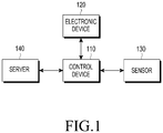
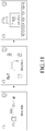
- FIG. 1 is a block diagram illustrating a configuration of a smart system according to a first embodiment of the present disclosure.
- the smart system collectively refers to a system for controlling electronic devices connected through a network in a predetermined space such as a smart home, a smart building, and a smart hotel.
- the smart system may include a control device 110, an electronic device 120, a sensor 130, and a server 140.
- the control device 110 may refer to a device configured to use sensing information received from the sensor 130 to determine a current situation of a user, including the state of electronic devices 120, the surrounding environment information, the state of the user, and the like, and control the electronic devices 120.
- the control device 110 may include a device configured to receive information for controlling an electronic device from the server 140.
- the control device 110 may provide a user interface for controlling an electronic device, and the user interface may be provided in various forms such as a sound effect, a voice message, a text message, an icon display, and an animation.
- the control device 110 may perform communication by being connected to all electronic devices 120 and sensors 130 located in a room, and a server 140 located inside or outside the room.
- control device 110 may transmit or receive information to or from other devices, and may transmit a signal for controlling other devices.
- the control device 110 may include a gateway for controlling an electronic device in a room.
- the control device 110 may be a user terminal or a remote controller, or may be located in a room, as a separate device such as a TV.
- the control device may be a terminal which is provided to a guest who checks in to a hotel during the stay, or may be a terminal which is provided during service hours when the guest uses facilities in a building.
- the user terminal may be, for example, a personal digital assistant (PDA) having a communication function, a smart phone, a mobile phone, a tablet PC, a notebook computer, or the like.
- PDA personal digital assistant
- the user terminal may be a wearable device such as a smart watch.
- the control device 110 includes a gateway.
- a program or an application for controlling an operation of an electronic device 120 may be installed in the user terminal.
- the electronic device 120 may include all types of electronic devices located in a house, an office, or a room, such as smart appliances, security devices, lighting devices, and energy devices.
- a smart appliance may be a TV, a refrigerator, a washing machine, a vacuum/robot cleaner, a digital video disc (DVD) player, an audio, an air conditioner, an oven, a washer, a dryer, an air cleaner, a set-top box, a TV box (e.g. Samsung HomeSyncTM, Apple TVTM, or Google TV TM), a gaming console, an electronic dictionary, a camcorder, an electronic photo frame, a lighting device, an alarm clock, an electric pot, an electric shower, electric blinds, electric curtains, or the like.
- TV box e.g. Samsung HomeSyncTM, Apple TVTM, or Google TV TM
- gaming console e.g. Samsung HomeSyncTM, Apple TVTM, or Google TV TM
- an electronic dictionary e.g. Samsung HomeSyncTM, Apple TVTM, or Google TV TM
- a security device may be a door lock, a security camera, a security sensor, or the like
- a lighting device may be a fluorescent lamp, a light emitting diode (LED) lighting device, or the like
- an energy device may be a power meter, an electric outlet, a multi-tap, an air conditioning controller, a power socket, or the like.
- the control device 110 may make a service request such as Do Not Disturb, Make Up Room, a fixture request, and a room service in addition to controlling electronic devices.
- an electronic device may be a combination of devices as described above. Further, it will be apparent to a person skilled in the art that electronic devices according to embodiments of the present disclosure are not limited to devices as described above.
- the plurality of electronic devices 120 may receive a control command from the control device 110 and operate according to the control command.
- the sensors 130 may refer to a device which provides information for controlling the electronic devices 120.
- the sensors 130 may include all types of sensors located in a house, an office, or a room, such as a water surface sensor, an illumination sensor, a temperature sensor, a humidity sensor, a sound sensor, a motion sensor, a proximity sensor, a door sensor, and a biosensor. Some of the sensors 130 may be provided in the control device 110 or the electronic devices 120.
- a sensor 130 may perform a sensing operation according to a predetermined time or a predetermined period, and may transmit, to the control device 110, sensing information periodically or at a requested time.
- the sensing information may be used to determine a current situation of a user, including the state of the electronic devices 120, the surrounding environment information, and the state of the user, and the like. Further, although not shown, the sensing information from the sensor 130 may be directly transmitted to the server 140 rather than to the control device 110.
- the server 140 may be a device which provides information for electronic device control, which is required for the control device 110 to control the electronic devices 120.
- the server may be a hotel management server, in the case of a home network, the server may be a home server, and in the case of a building, the server may be a building management server included in a building management system (BMS).
- BMS building management system
- the server 140 may provide, to the control device 110, a list of electronic devices 120 according to a room level, a control mode list, an electronic device list for each control mode as information for controlling the electronic devices 120 by the control device 110.
- the room level may be a room type such as a standard room, a deluxe room, or a suite room, and provided electronic devices 120 and provided control modes may be different depending on the room type.
- the server may store user profile information which can be used to display at least one candidate control mode selected according to an order of the probabilities of modes to be selected by a user from the highest probability to the lowest probability, among a plurality of control modes pre-configured by the control device 110, and provide the user profile information to the control device 110.
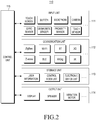
- FIG. 2 illustrates a detailed configuration of a control device 110 according to a first embodiment of the present disclosure.
- the control device 110 may include an input unit 111, a communication unit 112, a storage unit 113, an output unit 114, and a control unit 115.
- the input unit 111 may receive, from a user, an input of a command for selecting a control mode or a command for controlling an electronic device 120, and include a touch screen, a button, a microphone, a camera, a gyro sensor, a geomagnetic sensor, a proximity sensor, a touch sensor, or the like.
- the communication unit 112 may include communication modules for communicating with devices in a smart system, that is, an electronic device 120, a sensor 130, and a server 140.
- the communication module may include various wireless or wired communication protocol based modules such as a ZigBee module, a wireless LAN module such as Wi-Fi, a Bluetooth module, a 3G communication module, a Z-wave module, a Bluetooth low energy (BLE) module, a WiGig module, an infrared (IR) module, and the like.
- the communication unit 112 receives sensing information collected by the sensor, user profile information stored in the server, or the like or transmits a control command for the electronic device 120.
- the storage unit 113 may store information for controlling the electronic device 120, and the information for controlling the electronic device 120 may include user information, a control mode list, an electronic device list, and the like.
- the user information may be information received from the server 140 or user profile information including gender, age, nationality, hobby, and the like, as information pre-stored in the control device 110.
- the user profile information may be stored in a hotel server and may further include travel purpose, information on the number of companions and the companions, an airplane schedule, a hotel service used during the previous stay, a device control history, and the like.
- the electronic device list includes all electronic devices which can be controlled by the control device 120 in a room.
- the control mode list indicates modes pre-stored by a system administrator or the like, based on location of a user and a current state of the user, and electronic devices which can be controlled for each mode may pre-configured.
- the control modes may include, for example, a morning coffee mode, a TV watching mode, a wash mode, a sleep mode, a room service mode, an entertainment mode, a shower mode, and the like.
- Electronic devices which can be controlled for each mode may be different, and some of the electronic devices may overlap.
- an application for controlling an electronic device may be installed and stored in the storage unit 113.
- the output unit 114 provides information to a user for controlling the electronic device 120, and may include a display, a speaker, a vibration motor, and the like.
- the control unit 115 may include a CPU, a ROM in which a control program for controlling an electronic device 120 is stored, and a RAM which temporarily stores a signal or data input from the outside, or is used as a storage area for a task performed by the control device 110, and the control unit controls other components in the control device 110.
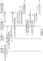
- FIG. 3 is a flowchart illustrating a method for controlling an electronic device according to a control mode by a smart system according to a first embodiment of the present disclosure.
- the server 140 collects user information through room reservation and check-in (operation 302) or transmits pre-stored user information to the control device 110 (operation 303).
- the sensor 130 in a room collects sensing information according to a predetermined time and a predetermined period (operation 304), and transmits the collected sensing information to the control device 110 (operation 305).
- the control device 110 may receive a command to start a control operation according to an input from a user through the input unit in a state in which the control device has received user information and sensing information from the server 140 and the sensor 130.
- the control device 110 determines location and a current state of the user by using the information collected from the server 140 and the sensor 130, and displays candidate control modes indicating some control modes which are selected according to a predetermined rule, among a plurality of pre-configured control modes, based on the determined location and current state of the user (operation 306).
- the control device 110 may additionally consider environmental information such as date, day of the week, time zone, temperature, humidity, and the amount of sunshine, which is collected through the Internet.
- the control device 110 may additionally consider user information stored in the user terminal or a control mode list, an electronic device list, and the like.
- Electronic devices which can be controlled according to control modes, respectively, and a set value for each control mode of each of the electronic devices may be changed by a system manager or a user who operates the control device 110, or may be configured to be automatically changed according to a use history of the user.
- the control device 110 may determine that the user will take a shower, turn on a TV, or go to sleep, according to a predetermined rule, and accordingly, the control device 110 may display, on an output unit, a shower mode, a music listening mode, a TV watching mode, and a sleep mode as a candidate control mode.
- the motion sensor detects motion of the user
- the control device 110 may display, on the output unit, a shower mode, a music listening mode, a TV watching mode, a morning coffee mode, a room service mode, and the like, as a candidate control mode, which correspond to actions the user is expected to take, based on sensing information of the motion sensor and a history of user's usual actions in the morning.
- the control device 110 When a user selects one control mode among candidate control modes through the input unit of the control device 110 (operation 307), the control device 110 receives current operation state information from the electronic device 120 (operation 308), and displays, on the output unit, a list of electronic devices which can be controlled in the selected control mode according to a predetermined scenario, based on the received operation state information (operation 311). For example, when a user selects a sleep mode, the control device 110 may display the sleep mode on a display unit so that a temperature controller, a lamp, a TV, an audio, a window, a door lock, an alarm clock, a curtain/blind, and the like can be controlled, respectively.
- a control value may be pre-configured so as to enable automatic control of some electronic devices according to a predetermined scenario for each control mode.
- the control device 110 may transmit, to a corresponding electronic device 120, an automatic control command for controlling electronic devices, which have a configured control value different from that of the current operation state, among some of the electronic devices, having fixed control values configured therein (operation 309).
- corresponding electronic devices 120 may perform a control operation according to the received control command (operation 310).
- the control command may be different depending on the characteristics of each of the electronic devices, and the control command may be a command for controlling a corresponding electronic device to be turned on/off, or may be a command for controlling a set value (level) of the electronic device.
- operation 309 and operation 310 occur before operation 311 in FIG. 3
- operation 309 and operation 310 may occur simultaneously with operation 311 or may occur after operation 311.
- the control value may be configured based on user information or a device control history according to a configuration condition such as a user's situation, time, day of the week, or room.
- control device 110 displays a control screen for controlling the selected electronic devices 120 on the display unit (operation 313).
- operation 314 the control device 110 may transmit the input control command to a corresponding electronic device 120 (operation 315), and the electronic device 120 may perform a control operation according to the received control command (operation 316).
- operation 308 may be omitted. That is, when a user selects one control mode among candidate control modes (operation 307), electronic devices related to the corresponding control mode may directly perform a control operation according to the corresponding control mode (operation 310).
- a first embodiment of the present disclosure described above corresponds to a case where a separate gateway is not included or a case where a gateway function is included in the control device.
- a gateway may be separately configured.
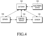
- FIG. 4 is a block diagram illustrating a configuration of a smart system according to a second embodiment of the present disclosure.
- a control device 150 of a smart system according to a second embodiment does not include a function of a gateway for controlling an electronic device 120. Therefore, a gateway 160 is separately provided.
- the electronic device 120, a sensor 130, and a server 140 are the same as those of the smart system according to the first embodiment, and thus the duplicated description thereof will be omitted.
- the control device 150 is a device for providing a user interface for controlling an electronic device according to a control mode, and an actual control operation is performed by the gateway 160.
- the gate way 160 may refer to a device for determining the state of electronic devices 120 by using sensing information received from the sensor 130, and controlling the electronic devices 120.
- the gateway 160 may perform communication by being connected to all electronic devices 120, sensors 130, and servers 140 which are located in a room. Accordingly, the gateway 160 may transmit or receive information to or from other devices, and may transmit a signal for controlling other devices.
- a separately configured gateway may include a communication unit, a storage unit, and a control unit, and the functions thereof are similar to those of the communication unit, the storage unit, and the control unit which are described in FIG. 2 .
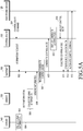
- FIG. 5 is a flowchart illustrating a method for controlling an electronic device according to a control mode by a smart system according to a second embodiment of the present disclosure.
- FIGS. 5A and 5B are similar to the first embodiment shown and described in FIG. 3 , but the control device 150 processes input from a user (operations 501, 510, 518, and 520), output (operations 509, 517, and 519) and information transmission and reception (operations 502, 508, 511, 516, and 521), and the gateway 160 uses information collected (operations 504 and 506) from the server 140 or the sensor 130 to perform candidate control mode recommendation (operation 507) and control operations (operations 511 to 522) according to a selected control mode.
- FIG. 6 illustrates an example of a candidate control mode according to an embodiment of the present disclosure.
- location, time, and action are determined based on sensing information
- two types of user situations are exemplified according to a combination of the sensing information
- candidate control modes are classified for each user situation. That is, a situation in which a user is located in a bed in a room in the morning and a user's waking-up motion is detected may be set as a first situation, and a candidate control mode in the first situation may be set to a morning coffee mode, a TV watching mode, a wash mode, a sleep mode, or a room service mode.
- a situation in which a user is located on a sofa in a room in the nighttime and a door sensor detects that the user has returned to the room may be set as a second situation, and a candidate control mode in the second situation may be set to a sleep mode, an entertainment mode, or a shower mode.
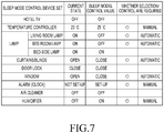
- FIG. 7 illustrates an example of detailed set values of electronic devices according to a sleep mode among control modes according to an embodiment of the present disclosure.
- An embodiment of FIG. 7 indicates a current operation state and a control value pre-configured with respect to a sleep mode, for each of electronic devices which can be controlled in the sleep mode, information on other electronic devices, each of which has a configured control value different from that of a current operation state and is thus required to be controlled, and a control method for the electronic devices.
- the control method for the electronic devices may be configured automatically or manually, and the control method may be predetermined according to the characteristics of the electronic devices, or may be changed depending on a user control history.
- a control command is automatically transmitted to electronic devices (a living room lamp, a bedroom lamp, curtains/blinds, and a window), each of which has a configured value different from that of a current operation state, among electronic devices for which control methods are automatically configured.
- electronic devices a living room lamp, a bedroom lamp, curtains/blinds, and a window
- a manual control is required for electronic devices (a temperature controller, an alarm (clock), and a humidifier) each of which has a configured value different from that of a current operation state, among electronic devices for which control methods are manually configured
- a user interface may be provided to allow a user to control the devices through a user terminal or a control device.
- the electronic device is controlled using a user terminal as a control device in a smart system in a hotel.
- the user terminal is registered as the control device in the smart system in the hotel at the time of check-in, so that the user terminal may operate as a control device for controlling electronic devices.
- the user terminal may be a personal terminal currently possessed by a user, or may be a public terminal provided to the user by a hotel at the time of check-in.
- a personal terminal currently possessed by a user is used as the control device, information required for controlling an electronic device, among user information stored in the user terminal, may be selected and configured to be shared with the smart system in the hotel.
- the hotel provides a public terminal
- user profile information stored in a server of the smart system in the hotel may be stored in the public terminal at the time of check-in.
- the server stores and manages all data for managing the hotel, and is connected to various facilities in the hotel, that is, is connected to electronic devices located in a room, a lobby, a restaurant, and a fitness center, and gateways for controlling the electronic devices through a network.
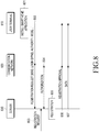
- FIG. 8 illustrates a procedure for registering a user terminal in a smart system for a control operation according to a third embodiment of the present disclosure.
- the procedure may be a procedure for registering a user terminal in a hotel smart system.
- a user terminal 810 installs an application for controlling electronic devices in a room and a hotel at the time of check-in (operation 801).
- the application may be restricted to be installed only in the user terminal 810 authorized through check-in.
- the server provides an authorization number for approving installation of an application to the user terminal 810 that has completed the check-in process, and a hotel server or an external server for providing an application allows only the user terminal 810 authorized through the authorization number to download the application.
- the application may provide limited functions depending on an allowed authority level of the user terminal 810.
- an application may selectively provide functions for inquiring information through a server 830, receiving alarm information from the server 830, and controlling electronic devices which can be controlled in a hotel, depending on the allowed authority level.
- the allowed authority level may be configured through the server 830 or the external server for providing the application.
- the available hotel service is differentiated, the facilities provided in the room are different, and the available facilities in the hotel are different. Accordingly, differentiated control functions may be provided for each user.
- the user terminal 810 executes the application and transmits a registration request message to the server 1030 through the application (operation 802).
- the registration request message includes at least one of an identifier (for example, an MS identifier (MSID) or an International Mobile Subscriber Identity (IMSI)), a login ID and a password, authority information, and operation mode information of the user terminal 810.
- MSID MS identifier
- IMSI International Mobile Subscriber Identity
- the server 830 receives a registration request for the user terminal 810 to be registered through its own user interface (operation 803), and registers the user terminal 810 (operation 805).
- the server 830 may authorize the user terminal 810, by using identification information obtained from the user terminal 810 or, in the case of a smart phone, by accessing a communication server which manages subscriber information of a corresponding mobile communication system from a user (operation 804).
- the server 830 may generate authority information of the user terminal 810 according to the authority result. Thereafter, the server 830 stores information on the user terminal 830 and manages the information by means of the registered user terminal 810 (operation 805).
- the server 830 transmits, to the user terminal 810, a registration approval message indicating that the information on the user terminal 810 is successfully registered (operation 806). Thereafter, the server 830 may transmit a variety of information for controlling electronic devices to the user terminal 810 (operation 807).
- the information for control may include user profile information stored in the server 830, a control mode list, an electronic device list for each control mode, and a control value and a control method for each of electronic devices for each control mode.
- the information for control may also include control information with respect to various facilities in the hotel.
- the user terminal 810 that has completed the processes of FIG. 8 may then operate as a control device for controlling electronic devices in the hotel. That is, when a user enters a room, the user terminal 810 may control electronic devices in the room according to the control operations of FIG. 3 .
- the user terminal may select hotel facilities around the user according to a predetermined rule to display the same on the user terminal, based on information received from the server through the registration process of the user terminal and location information of the terminal.
- the user terminal may display a control list which can be controlled by the user terminal with respect to the selected facility on the user terminal.
- the user terminal may display a reservation service, menu information, price information, and the like of the selected restaurant.
- the restaurant reservation service is selected by the user, the user terminal may receive an input of information required for restaurant reservation and transmit the information to the restaurant.
- an operation of receiving an input of a piece of the reservation information may be omitted using user information pre-stored in the user terminal.
- the user terminal may display a fitness club use method, exercise equipment-specific reservability, and the like.
- the same control processes as those of the smart system described above may be performed.
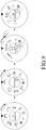
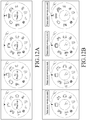
- FIG. 9 illustrates an example of a user interface screen of a control device according to an embodiment of the present disclosure, and illustrates an example of a user interface screen which displays a candidate control mode.
- candidate control modes selected according to a predetermined user situation among a plurality of pre-configured control modes, are circularly arranged, in particular, a control mode having the highest probability of modes to be selected by a user may be arranged to be located on the central axis of a circular button, control modes having the next highest probability of selection may be arranged to be located near the center axis of the circular button.
- the modes having a high probability of being selected may be prioritized based on user profile information.
- the size or color of an image indicating a control mode located on the current central axis may be displayed in the center of the circular button to be distinguished from the other images, and guiding words for controlling the control mode located on the current central axis may be displayed as a text in the center of the circular button.
- the user may move positions where control modes are displayed through click and rotary (The click may be an input scheme used for icon selection and control input, and the rotary may be an input scheme used to move the position of an icon through rotation or to adjust a configuration/control level.
- a temperature may be raised or lowered by a temperature controller through the rotary and then is configured to the adjusted temperature through the click.), touch, hovering, gesture, etc., and further, guiding words to be displayed in the center of the circular button may be changed according to the position-changed control mode.
- the screen may be switched to a screen for more precisely controlling the selected control mode.
- the control device may vibrate or allow a LED provided in the control device to emit light by informing the user of the selected control mode or device.
- the control device may recommend a shower mode, a music listening mode, a TV watching mode, a sleep mode, a rest mode, a Do Not Disturb mode, a door lock locking mode, etc., as candidate control modes.
- the control device When the user rotates the control device to select the sleep mode among the candidate control modes, the control device displays a screen for configuring a sleep mode entry time, and the user may rotate the control device to configure the control device to enter the sleep mode after 30 minutes.
- the control device may display devices which can be controlled in the sleep mode on a screen thereof, and when the user selects a temperature controller, the control device may display a detailed screen for configuring a desired temperature in the room.
- FIG. 10 illustrates an example of a user interface screen of a control device according to another embodiment of the present disclosure, and illustrates an example of a user interface for supporting voice guidance.
- the circular button is displayed in a rotatable form.
- candidate control modes selected according to a predetermined rule among a plurality of pre-configured control modes are circularly arranged on the circular button, in particular, the size or color of an image indicating a control mode having the highest probability of modes to be selected by a user is displayed to be distinguished from the other images.
- voice guidance for the control mode having the highest probability of modes to be selected may be output before a user's selection.
- guiding words may be displayed on the screen with voice guidance.
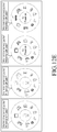
- FIG. 11 illustrates another example of a user interface screen of a control device according to an embodiment of the present disclosure.
- candidate control modes selected according to a predetermined user situation among a plurality of pre-configured control modes are arranged in a line, in particular, a control mode having the highest probability of modes to be selected by a user may be located at the center of the screen, and control modes having the next highest probability of selection may be arranged on both sides in order.
- the size or color of an image indicating a control mode located at the center of the screen may be displayed to be distinguished from the other images, and an icon may be displayed to become smaller as the icon moves away from the center of the screen.
- guidance words for controlling the control mode located at the center of the screen may be displayed as a text in the top or the bottom of the screen, or may be output as a voice through a speaker.
- a user may move icons to the left or the right using finger touch, and accordingly, the control mode located at the center of the screen may be changed and the guidance words may be changed according to the changed control mode.
- the screen may be switched to a screen for more precisely controlling the selected control mode.
- FIG. 11 illustrates an example of a case where a sleep mode is selected.
- the screen When the sleep mode is selected, the screen is switched to a screen in which electronic devices which can be controlled in the sleep mode are arranged, and when one electronic device is selected among the electronic devices, the screen is switched to a screen for controlling the selected electronic device.
- a temperature controller is selected, and a numeric keypad for inputting a temperature configuration value may be displayed at the bottom of the screen.
- control device is shown in a circular shape and a quadrilateral shape, but the present disclosure is not limited thereto, and may be implemented in various shapes such as a triangle, a pentagon, a hexagon, an octagon, a star shape, and a diamond shape.
- FIGS. 9 to 11 illustrate an example of a case where a screen is switched through finger touch. However, the present disclosure is not limited thereto, and various input schemes may be applied.
- each control mode may be displayed, on a screen, using a tab menu as well as an icon.
- FIGS. 12A to 12E illustrate various examples of an interface in a case where a control device according to an embodiment of the present disclosure is implemented in a circular shape.
- FIG. 12A illustrates an example in which a user input is input through button click and rotary and displays a text for a selected control mode in a central circular area of a control device.
- FIG. 12B illustrates an example in which a user input is input through button click and rotary and a guidance voice for helping the user input is output.
- FIG. 12C illustrates an example in which an user input is input as a voice through a microphone and a text for a selected control mode is displayed in a central circular area.
- FIG. 12D illustrates an example in which a user input is input as a voice through a microphone and a guidance voice for helping the user input is output. In each of the cases of FIGS.
- icons for each control mode are displayed in the same size and color, the icons are displayed in different sizes and the same colors, the icons are displayed in the same sizes and different colors, or icons are displayed in different sizes and colors.
- the contrast may be displayed differently for each icon instead of displaying different colors.
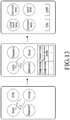
- FIG. 13 illustrates an example of a user interface screen of a control device according to the another embodiment of the present disclosure, and illustrates a user interface screen to be displayed on a user terminal after a user checks in at a hotel using the user terminal according to a third embodiment of the present disclosure.
- a user terminal is registered in a smart system in a hotel, and accordingly, the user terminal may operate as a control device for controlling electronic devices.
- the user terminal having completed the check-in executes an application for device control, a user interface as shown in the first diagram of FIG. 13 may be displayed.
- a user desires to configure devices in a room in advance before arriving at the room, the user may touch and select "Room” among Room, GYM, Restaurant, and Lounge displayed on a screen. Then, as shown in the second diagram, a plurality of recommendation control modes may be displayed at the bottom of the screen, and when the user selects one of the modes, devices which can be controlled according to the selected control mode may be displayed at the top of the screen.
- lamps which can be controlled in the room may be displayed as shown in the right diagram, and images for on/off control may be displayed at the bottom of the screen.
- the user touches a corresponding image and then perform appropriate controls for each location.
- a location receiving device of the user terminal may track the location of the user in the hotel, and may display images of places near the place where the user is currently located on a user interface screen to help user's selection.
- FIGS. 9 to 13 illustrate an example of a user interface for device control according to an embodiment of the present disclosure.
- the user interface according to an embodiment of the present disclosure is not limited thereto, and it will be apparent to a person skilled in the art that the user interface may be modified and implemented in various forms.
- Particular aspects of the present disclosure may be implemented as a computer-readable code in a computer-readable recording medium.
- a method and a device may be implemented in the form of hardware, software, or a combination of hardware and software.
- Such software may be stored, for example, in a volatile or nonvolatile storage device, or a storage medium which is readable by a machine (e.g., a computer) while being optically or magnetically recordable.
- a method according to an embodiment of the present disclosure may be implemented by a computer or a mobile terminal including a control unit and a memory, and the memory is an example of a storage medium which is readable by using a program including instructions for implementing embodiments of the present disclosure or a device suitable for storing programs.
Landscapes
- Engineering & Computer Science (AREA)
- Computer Networks & Wireless Communication (AREA)
- Signal Processing (AREA)
- Automation & Control Theory (AREA)
- General Engineering & Computer Science (AREA)
- Theoretical Computer Science (AREA)
- Human Computer Interaction (AREA)
- General Physics & Mathematics (AREA)
- General Health & Medical Sciences (AREA)
- Medical Informatics (AREA)
- Computing Systems (AREA)
- Health & Medical Sciences (AREA)
- Physics & Mathematics (AREA)
- Selective Calling Equipment (AREA)
- Telephonic Communication Services (AREA)
- Management, Administration, Business Operations System, And Electronic Commerce (AREA)
Claims (12)
- Verfahren zum Steuern eines elektronischen Geräts durch ein Steuergerät, wobei das Verfahren Folgendes umfasst:Sammeln von Erfassungsinformationen von mindestens einem Sensor (305) durch das Steuergerät;Identifizieren von benutzerbezogenen Informationen durch das Steuergerät basierend auf den gesammelten Erfassungsinformationen, wobei die benutzerbezogenen Informationen einen Standort und einen aktuellen Zustand eines Benutzers umfassen;Identifizieren, durch das Steuergerät, von mindestens einem Kandidatensteuermodus, der den benutzerbezogenen Informationen entspricht, aus einer Vielzahl von vorgespeicherten Steuermodi,wobei jeder Steuermodus vorkonfigurierte Steuerwerte für eine Vielzahl von elektronischen Geräten umfasst, die in dem Steuermodus gesteuert werden können;Anzeigen des mindestens einen Kandidatensteuermodus, einschließlich Informationen für jedes der elektronischen Geräte, die in dem mindestens einen Kandidatensteuermodus (306) gesteuert werden können, durch das Steuergerät, wobei der mindestens eine Kandidatensteuermodus gemäß einer Wahrscheinlichkeitsreihenfolge der vom Benutzer auszuwählenden Kandidatensteuermodi angezeigt wird, wobei die Wahrscheinlichkeit basierend auf den benutzerbezogenen Informationen bestimmt wird;Empfangen einer Auswahleingabe durch das Steuergerät unter Verwendung eines kreisförmigen Knopfes, der drehbar ist, um einen Steuermodus aus dem mindestens einen angezeigten Kandidatensteuermodus auszuwählen; undÜbertragen eines Steuerbefehls durch das Steuergerät zum gleichzeitigen Steuern der Vielzahl von elektronischen Geräten, die in dem einen Steuermodus gesteuert werden können, als Reaktion auf die Auswahleingabe (315),wobei der mindestens eine Kandidatensteuermodus mit der höchsten Auswahlwahrscheinlichkeit angeordnet ist, um sich in der Nähe einer Mittelachse des kreisförmigen Knopfes zu befinden.
- Verfahren nach Anspruch 1, ferner umfassend:Empfangen von Benutzerprofilinformationen und/oder Informationen zum Steuern des elektronischen Geräts von einem Server (303) durch das Steuergerät,wobei die benutzerbezogenen Informationen basierend auf den Benutzerprofilinformationen, den Informationen zum Steuern des elektronischen Geräts und den gesammelten Erfassungsinformationen identifiziert werden.
- Verfahren nach Anspruch 2, wobei die Informationen zum Steuern des elektronischen Geräts mindestens eines von einer Liste elektronischer Geräte, einer Steuermodusliste und einem Steuerwert für jedes der elektronischen Geräte beinhalten, die in jedem der Vielzahl von vorgespeicherten Steuermodi gesteuert werden können.
- Verfahren nach Anspruch 1, ferner umfassend:
Empfangen von Betriebszustandsinformationen von elektronischen Geräten von den elektronischen Geräten (308) nach dem Übertragen des Steuerbefehls; und Übertragen des Steuerbefehls für jedes der Vielzahl von elektronischen Geräten entsprechend dem einen Steuermodus (309) basierend auf den empfangenen Betriebszustandsinformationen des elektronischen Geräts. - Verfahren nach Anspruch 1, wobei der mindestens eine Kandidatensteuermodus kreisförmig auf der kreisförmigen Schaltfläche angeordnet ist.
- Verfahren nach Anspruch 1, wobei der eine Steuermodus durch Drehen des kreisförmigen Knopfes ausgewählt wird.
- Steuergerät (110) zum Steuern eines elektronischen Geräts, wobei das Steuergerät Folgendes umfasst:eine Kommunikationseinheit (112), die konfiguriert ist, um Erfassungsinformationen von mindestens einem Sensor zu sammeln und mindestens ein Kommunikationsmodul zum Durchführen einer Kommunikation mit dem elektronischen Gerät enthält;eine Eingabe-/Ausgabeeinheit (111/114), die konfiguriert ist, um eine Benutzerschnittstelle zum Steuern eines Betriebs des elektronischen Geräts bereitzustellen;eine Speichereinheit (113), die konfiguriert ist, um eine Vielzahl von Steuermodi zu speichern, wobei jeder Steuermodus vorkonfigurierte Steuerwerte für eine Vielzahl von elektronischen Geräten umfasst, die in dem Steuermodus gesteuert werden können; undeine Steuereinheit (115), die konfiguriert ist, um Folgendes zu steuern: Vorgänge zum Identifizieren von benutzerbezogenen Informationen basierend auf den gesammelten Erfassungsinformationen,wobei die benutzerbezogenen Informationen einen Standort und einen aktuellen Zustand eines Benutzers umfassen, Identifizieren mindestens eines Kandidatensteuermodus entsprechend den benutzerbezogenen Informationen aus der Vielzahl von Steuermodi, Anzeigen von mindestens einem Kandidatensteuermodus, einschließlich Informationen für jedes der elektronischen Geräte, die in dem mindestens einen Kandidatensteuermodus gesteuert werden können,wobei der mindestens eine Kandidatensteuermodus gemäß einer Wahrscheinlichkeitsreihenfolge der vom Benutzer auszuwählenden Kandidatensteuermodi angezeigt wird,wobei die Wahrscheinlichkeit basierend auf den benutzerbezogenen Informationen bestimmt wird, Empfangen einer Auswahleingabe unter Verwendung einer kreisförmigen Taste, die drehbar ist, um einen Steuermodus aus dem mindestens einen angezeigten Kandidatensteuermodus auszuwählen, und Übertragen eines Steuerbefehls, der gleichzeitig die Vielzahl von elektronischen Geräten steuert, die in dem einen Steuermodus gesteuert werden können, als Reaktion auf die Auswahleingabe,wobei der mindestens eine Kandidatensteuermodus mit der höchsten Auswahlwahrscheinlichkeit angeordnet ist, um sich in der Nähe einer Mittelachse des kreisförmigen Knopfes zu befinden.
- Gerät nach Anspruch 7, wobei die Steuereinheit (115) konfiguriert ist, um folgende Vorgänge zu steuern Empfangen von Benutzerprofilinformationen und/oder Informationen zum Steuern des elektronischen Geräts von einem Server, und
Identifizieren der mindestens einen der Benutzerprofilinformationen, der Informationen zum Steuern des elektronischen Geräts, um die Situation des Benutzers zu bestimmen, und der gesammelten Erfassungsinformationen. - Gerät nach Anspruch 8, wobei die Informationen zum Steuern des elektronischen Geräts mindestens eines von einer elektronischen Geräteliste, einer Steuermodusliste und einem Steuerwert für jedes der elektronischen Geräte beinhalten, die in jedem der Vielzahl von vorgespeicherten Steuermodi gesteuert werden können.
- Gerät nach Anspruch 7, wobei die Steuereinheit (115) konfiguriert ist, um Folgendes zu steuern:
Vorgänge zum Empfangen von Betriebszustandsinformationen elektronischer Geräte von den elektronischen Geräten und zum Übertragen eines Steuerbefehls für jede der Vielzahl von elektronischen Geräten entsprechend dem einen Steuermodus, basierend auf den empfangenen Betriebszustandsinformationen des elektronischen Geräts. - Gerät nach Anspruch 7, wobei der mindestens eine Kandidatensteuermodus kreisförmig auf dem kreisförmigen Knopf angeordnet ist.
- Gerät nach Anspruch 7, wobei der eine Steuermodus durch Drehen des kreisförmigen Knopfes ausgewählt wird.
Applications Claiming Priority (2)
| Application Number | Priority Date | Filing Date | Title |
|---|---|---|---|
| KR1020150185337A KR102487902B1 (ko) | 2015-12-23 | 2015-12-23 | 전자기기를 제어하는 방법 및 장치 |
| PCT/KR2016/015170 WO2017111532A1 (ko) | 2015-12-23 | 2016-12-23 | 전자기기를 제어하는 방법 및 장치 |
Publications (3)
| Publication Number | Publication Date |
|---|---|
| EP3355552A1 EP3355552A1 (de) | 2018-08-01 |
| EP3355552A4 EP3355552A4 (de) | 2018-09-05 |
| EP3355552B1 true EP3355552B1 (de) | 2021-07-28 |
Family
ID=59089639
Family Applications (1)
| Application Number | Title | Priority Date | Filing Date |
|---|---|---|---|
| EP16879399.0A Active EP3355552B1 (de) | 2015-12-23 | 2016-12-23 | Verfahren und vorrichtung zur steuerung einer elektronischen vorrichtung |
Country Status (6)
| Country | Link |
|---|---|
| US (1) | US11374782B2 (de) |
| EP (1) | EP3355552B1 (de) |
| JP (1) | JP7073259B2 (de) |
| KR (1) | KR102487902B1 (de) |
| CN (1) | CN108476232B (de) |
| WO (1) | WO2017111532A1 (de) |
Families Citing this family (24)
| Publication number | Priority date | Publication date | Assignee | Title |
|---|---|---|---|---|
| US10742441B2 (en) | 2017-04-13 | 2020-08-11 | Johnson Controls Technology Company | Unified building management system |
| US11025563B2 (en) | 2017-04-13 | 2021-06-01 | Johnson Controls Technology Company | Space-aware network switch |
| DE202018006928U1 (de) * | 2017-04-13 | 2024-07-19 | Johnson Controls Technology Company | Gebäudeverwaltungssystem mit Raumprofilen |
| JP6941516B2 (ja) * | 2017-09-14 | 2021-09-29 | 立川ブラインド工業株式会社 | 信号処理装置及びシステム |
| KR102012933B1 (ko) * | 2018-02-22 | 2019-08-21 | 한전케이디엔 주식회사 | 스마트 홈 시스템 |
| KR102671741B1 (ko) | 2018-05-07 | 2024-06-04 | 구글 엘엘씨 | 다양한 연결 디바이스를 제어하기 위한 복합 그래픽 어시스턴트 인터페이스 제공 |
| JP6814770B2 (ja) * | 2018-07-04 | 2021-01-20 | ソフトバンク株式会社 | 室内管理システム、室内管理装置、室内管理方法および室内管理プログラム |
| CN110944028A (zh) * | 2018-09-21 | 2020-03-31 | 阿里巴巴集团控股有限公司 | 一种客房管理方法、服务器、系统及存储介质 |
| CN112352204B (zh) | 2018-10-08 | 2024-08-16 | 谷歌有限责任公司 | 简要传达智能电器状态 |
| USD916099S1 (en) * | 2019-04-04 | 2021-04-13 | Ansys, Inc. | Electronic visual display with structure modeling tool graphical user interface |
| DK180129B1 (en) * | 2019-05-31 | 2020-06-02 | Apple Inc. | User activity shortcut suggestions |
| KR102868898B1 (ko) * | 2019-07-19 | 2025-10-02 | 엘지전자 주식회사 | 가전기기 및 이를 제어하기 위한 방법 |
| KR102092300B1 (ko) * | 2019-09-16 | 2020-03-23 | 주식회사 블루티움 | 멀티 제어 장치 |
| CN112020157A (zh) * | 2020-08-18 | 2020-12-01 | 上海冷溪安全科技有限公司 | 一种与预警系统交互的方法和手持设备 |
| CN112306364B (zh) * | 2020-11-19 | 2023-02-10 | Oppo广东移动通信有限公司 | IoT设备的控制方法、装置、终端及存储介质 |
| CN112860164B (zh) * | 2021-01-22 | 2022-02-08 | 璞真生活有限公司 | 香薰机的控制方法、控制装置、移动终端及存储介质 |
| JP7643095B2 (ja) * | 2021-03-09 | 2025-03-11 | 富士フイルムビジネスイノベーション株式会社 | 情報処理装置およびプログラム |
| EP4380112A4 (de) * | 2022-02-07 | 2025-01-29 | Samsung Electronics Co., Ltd. | Server zur steuerung eines heimnetzwerks auf basis des schlafzustands und betriebsverfahren dafür |
| CN117204116A (zh) * | 2022-03-22 | 2023-12-08 | 北京小米移动软件有限公司 | 通感业务的处理方法、装置、通信设备及存储介质 |
| WO2024155059A1 (ko) * | 2023-01-17 | 2024-07-25 | 삼성전자 주식회사 | 사용자의 콘텍스트에 따라 복수의 전자기기들을 제어하는 방법 및 이를 수행하기 위한 컴퓨팅 디바이스 |
| CN120457659A (zh) | 2023-01-17 | 2025-08-08 | 三星电子株式会社 | 用于根据用户的上下文来控制多个电子装置的方法以及用于执行该方法的计算装置 |
| CN120283279A (zh) * | 2023-03-13 | 2025-07-08 | 三星电子株式会社 | 服务器装置、服务器装置的控制方法、以及iot系统 |
| USD1111025S1 (en) * | 2023-04-06 | 2026-02-03 | Atlas Copco Industrial Technique Ab | Display screen with graphical user interface |
| JP2025119331A (ja) * | 2024-02-01 | 2025-08-14 | Nttドコモビジネス株式会社 | 情報処理装置、情報処理方法、情報処理プログラム及び情報処理システム |
Citations (2)
| Publication number | Priority date | Publication date | Assignee | Title |
|---|---|---|---|---|
| US20150153057A1 (en) * | 2012-04-05 | 2015-06-04 | Google Inc. | Distribution of call-home events over time to ameliorate high communications and computation peaks in intelligent control system |
| US20180069721A1 (en) * | 2011-07-27 | 2018-03-08 | Lg Electronics Inc. | Laundry machine and online system including the same |
Family Cites Families (16)
| Publication number | Priority date | Publication date | Assignee | Title |
|---|---|---|---|---|
| JP2004180260A (ja) | 2002-03-20 | 2004-06-24 | Sanyo Electric Co Ltd | 信号変換装置 |
| KR101545582B1 (ko) * | 2008-10-29 | 2015-08-19 | 엘지전자 주식회사 | 단말기 및 그 제어 방법 |
| KR101556972B1 (ko) | 2009-05-11 | 2015-10-02 | 엘지전자 주식회사 | 세탁기를 제어하는 휴대 단말기 및 그 동작 방법 |
| JP5156816B2 (ja) * | 2010-11-02 | 2013-03-06 | シャープ株式会社 | 携帯端末装置 |
| KR101885723B1 (ko) * | 2011-09-30 | 2018-09-10 | 삼성전자 주식회사 | 사용자 정보에 따라 전자 기기 접근 방법 및 이를 구비한 장치 |
| WO2014066879A2 (en) | 2012-10-28 | 2014-05-01 | Hillcrest Laboratories, Inc. | Context awareness for smart televisions |
| US10318121B2 (en) * | 2012-12-28 | 2019-06-11 | Panasonic Intellectual Property Corporation Of America | Control method |
| US20140244001A1 (en) * | 2013-02-25 | 2014-08-28 | Qualcomm Incorporated | Controlling many different devices from a smart controller |
| US10181960B2 (en) | 2013-09-05 | 2019-01-15 | Samsung Electronics Co., Ltd. | Method and apparatus for configuring and recommending device action using user context |
| KR102233602B1 (ko) | 2013-09-05 | 2021-03-30 | 삼성전자 주식회사 | 사용자 컨텍스트를 이용한 디바이스 동작의 설정 및 추천 방법 및 장치 |
| US10025463B2 (en) * | 2013-09-18 | 2018-07-17 | Vivint, Inc. | Systems and methods for home automation scene control |
| KR102114219B1 (ko) | 2013-10-10 | 2020-05-25 | 삼성전자주식회사 | 오디오 시스템 및 오디오 출력 방법, 그리고 스피커 장치 |
| US9930519B2 (en) * | 2013-11-21 | 2018-03-27 | Samsung Electronics Co., Ltd. | Method and apparatus for controlling home devices on group basis based upon history of the home devices |
| US9989942B2 (en) | 2013-12-30 | 2018-06-05 | Qualcomm Incorporated | Preemptively triggering a device action in an Internet of Things (IoT) environment based on a motion-based prediction of a user initiating the device action |
| KR101554188B1 (ko) * | 2014-06-05 | 2015-09-18 | 엘지전자 주식회사 | 웨어러블 디바이스 및 그 제어 방법 |
| US20170097743A1 (en) * | 2015-10-05 | 2017-04-06 | Quixey, Inc. | Recommending Applications |
-
2015
- 2015-12-23 KR KR1020150185337A patent/KR102487902B1/ko active Active
-
2016
- 2016-12-23 WO PCT/KR2016/015170 patent/WO2017111532A1/ko not_active Ceased
- 2016-12-23 JP JP2018532583A patent/JP7073259B2/ja active Active
- 2016-12-23 EP EP16879399.0A patent/EP3355552B1/de active Active
- 2016-12-23 US US16/061,197 patent/US11374782B2/en active Active
- 2016-12-23 CN CN201680075898.6A patent/CN108476232B/zh active Active
Patent Citations (2)
| Publication number | Priority date | Publication date | Assignee | Title |
|---|---|---|---|---|
| US20180069721A1 (en) * | 2011-07-27 | 2018-03-08 | Lg Electronics Inc. | Laundry machine and online system including the same |
| US20150153057A1 (en) * | 2012-04-05 | 2015-06-04 | Google Inc. | Distribution of call-home events over time to ameliorate high communications and computation peaks in intelligent control system |
Also Published As
| Publication number | Publication date |
|---|---|
| CN108476232A (zh) | 2018-08-31 |
| KR102487902B1 (ko) | 2023-01-12 |
| KR20170075545A (ko) | 2017-07-03 |
| US11374782B2 (en) | 2022-06-28 |
| EP3355552A4 (de) | 2018-09-05 |
| EP3355552A1 (de) | 2018-08-01 |
| WO2017111532A1 (ko) | 2017-06-29 |
| JP7073259B2 (ja) | 2022-05-23 |
| CN108476232B (zh) | 2021-10-01 |
| JP2019507973A (ja) | 2019-03-22 |
| US20180367330A1 (en) | 2018-12-20 |
Similar Documents
| Publication | Publication Date | Title |
|---|---|---|
| EP3355552B1 (de) | Verfahren und vorrichtung zur steuerung einer elektronischen vorrichtung | |
| KR102146738B1 (ko) | 홈 네트워크 시스템에서 홈 디바이스를 원격으로 제어하는 방법 및 장치 | |
| JP6903713B2 (ja) | ネットワーク接続されたサーモスタットを管理するための方法 | |
| US9930519B2 (en) | Method and apparatus for controlling home devices on group basis based upon history of the home devices | |
| EP3072257B1 (de) | Verfahren und vorrichtung zur steuerung von heimvorrichtungen auf gruppenbasis in einem heimnetzwerksystem | |
| US12081830B2 (en) | Video integration with home assistant | |
| KR102344021B1 (ko) | 디바이스를 제어하는 방법 및 장치 | |
| KR20220001903A (ko) | 클라우드 플랫폼 기반의 공동주택의 스마트홈 시스템 | |
| JP7770554B2 (ja) | 階層的モバイルアプリケーションの起動 | |
| US20250167561A1 (en) | Battery Management and Optimization Using Voice Integration Systems |
Legal Events
| Date | Code | Title | Description |
|---|---|---|---|
| STAA | Information on the status of an ep patent application or granted ep patent |
Free format text: STATUS: THE INTERNATIONAL PUBLICATION HAS BEEN MADE |
|
| PUAI | Public reference made under article 153(3) epc to a published international application that has entered the european phase |
Free format text: ORIGINAL CODE: 0009012 |
|
| STAA | Information on the status of an ep patent application or granted ep patent |
Free format text: STATUS: REQUEST FOR EXAMINATION WAS MADE |
|
| 17P | Request for examination filed |
Effective date: 20180423 |
|
| AK | Designated contracting states |
Kind code of ref document: A1 Designated state(s): AL AT BE BG CH CY CZ DE DK EE ES FI FR GB GR HR HU IE IS IT LI LT LU LV MC MK MT NL NO PL PT RO RS SE SI SK SM TR |
|
| AX | Request for extension of the european patent |
Extension state: BA ME |
|
| A4 | Supplementary search report drawn up and despatched |
Effective date: 20180807 |
|
| RIC1 | Information provided on ipc code assigned before grant |
Ipc: H04W 4/70 20180101ALI20180801BHEP Ipc: H04L 29/08 20060101AFI20180801BHEP Ipc: H04L 12/28 20060101ALI20180801BHEP |
|
| DAV | Request for validation of the european patent (deleted) | ||
| DAX | Request for extension of the european patent (deleted) | ||
| STAA | Information on the status of an ep patent application or granted ep patent |
Free format text: STATUS: EXAMINATION IS IN PROGRESS |
|
| 17Q | First examination report despatched |
Effective date: 20191023 |
|
| GRAP | Despatch of communication of intention to grant a patent |
Free format text: ORIGINAL CODE: EPIDOSNIGR1 |
|
| STAA | Information on the status of an ep patent application or granted ep patent |
Free format text: STATUS: GRANT OF PATENT IS INTENDED |
|
| INTG | Intention to grant announced |
Effective date: 20210302 |
|
| RIN1 | Information on inventor provided before grant (corrected) |
Inventor name: KIM, YANG-WOOK Inventor name: KANG, JAE-EUN Inventor name: LEE, CHANG-HYUN Inventor name: JUNG, JAE-HO Inventor name: KIM, KYUNG-JAE |
|
| GRAS | Grant fee paid |
Free format text: ORIGINAL CODE: EPIDOSNIGR3 |
|
| GRAA | (expected) grant |
Free format text: ORIGINAL CODE: 0009210 |
|
| STAA | Information on the status of an ep patent application or granted ep patent |
Free format text: STATUS: THE PATENT HAS BEEN GRANTED |
|
| AK | Designated contracting states |
Kind code of ref document: B1 Designated state(s): AL AT BE BG CH CY CZ DE DK EE ES FI FR GB GR HR HU IE IS IT LI LT LU LV MC MK MT NL NO PL PT RO RS SE SI SK SM TR |
|
| REG | Reference to a national code |
Ref country code: GB Ref legal event code: FG4D |
|
| REG | Reference to a national code |
Ref country code: CH Ref legal event code: EP |
|
| REG | Reference to a national code |
Ref country code: DE Ref legal event code: R096 Ref document number: 602016061401 Country of ref document: DE |
|
| REG | Reference to a national code |
Ref country code: AT Ref legal event code: REF Ref document number: 1415777 Country of ref document: AT Kind code of ref document: T Effective date: 20210815 |
|
| REG | Reference to a national code |
Ref country code: IE Ref legal event code: FG4D |
|
| REG | Reference to a national code |
Ref country code: LT Ref legal event code: MG9D |
|
| REG | Reference to a national code |
Ref country code: DE Ref legal event code: R079 Ref document number: 602016061401 Country of ref document: DE Free format text: PREVIOUS MAIN CLASS: H04L0029080000 Ipc: H04L0065000000 |
|
| REG | Reference to a national code |
Ref country code: NL Ref legal event code: MP Effective date: 20210728 |
|
| REG | Reference to a national code |
Ref country code: AT Ref legal event code: MK05 Ref document number: 1415777 Country of ref document: AT Kind code of ref document: T Effective date: 20210728 |
|
| PG25 | Lapsed in a contracting state [announced via postgrant information from national office to epo] |
Ref country code: HR Free format text: LAPSE BECAUSE OF FAILURE TO SUBMIT A TRANSLATION OF THE DESCRIPTION OR TO PAY THE FEE WITHIN THE PRESCRIBED TIME-LIMIT Effective date: 20210728 Ref country code: ES Free format text: LAPSE BECAUSE OF FAILURE TO SUBMIT A TRANSLATION OF THE DESCRIPTION OR TO PAY THE FEE WITHIN THE PRESCRIBED TIME-LIMIT Effective date: 20210728 Ref country code: FI Free format text: LAPSE BECAUSE OF FAILURE TO SUBMIT A TRANSLATION OF THE DESCRIPTION OR TO PAY THE FEE WITHIN THE PRESCRIBED TIME-LIMIT Effective date: 20210728 Ref country code: NO Free format text: LAPSE BECAUSE OF FAILURE TO SUBMIT A TRANSLATION OF THE DESCRIPTION OR TO PAY THE FEE WITHIN THE PRESCRIBED TIME-LIMIT Effective date: 20211028 Ref country code: NL Free format text: LAPSE BECAUSE OF FAILURE TO SUBMIT A TRANSLATION OF THE DESCRIPTION OR TO PAY THE FEE WITHIN THE PRESCRIBED TIME-LIMIT Effective date: 20210728 Ref country code: PT Free format text: LAPSE BECAUSE OF FAILURE TO SUBMIT A TRANSLATION OF THE DESCRIPTION OR TO PAY THE FEE WITHIN THE PRESCRIBED TIME-LIMIT Effective date: 20211129 Ref country code: LT Free format text: LAPSE BECAUSE OF FAILURE TO SUBMIT A TRANSLATION OF THE DESCRIPTION OR TO PAY THE FEE WITHIN THE PRESCRIBED TIME-LIMIT Effective date: 20210728 Ref country code: BG Free format text: LAPSE BECAUSE OF FAILURE TO SUBMIT A TRANSLATION OF THE DESCRIPTION OR TO PAY THE FEE WITHIN THE PRESCRIBED TIME-LIMIT Effective date: 20211028 Ref country code: AT Free format text: LAPSE BECAUSE OF FAILURE TO SUBMIT A TRANSLATION OF THE DESCRIPTION OR TO PAY THE FEE WITHIN THE PRESCRIBED TIME-LIMIT Effective date: 20210728 Ref country code: SE Free format text: LAPSE BECAUSE OF FAILURE TO SUBMIT A TRANSLATION OF THE DESCRIPTION OR TO PAY THE FEE WITHIN THE PRESCRIBED TIME-LIMIT Effective date: 20210728 Ref country code: RS Free format text: LAPSE BECAUSE OF FAILURE TO SUBMIT A TRANSLATION OF THE DESCRIPTION OR TO PAY THE FEE WITHIN THE PRESCRIBED TIME-LIMIT Effective date: 20210728 |
|
| PG25 | Lapsed in a contracting state [announced via postgrant information from national office to epo] |
Ref country code: PL Free format text: LAPSE BECAUSE OF FAILURE TO SUBMIT A TRANSLATION OF THE DESCRIPTION OR TO PAY THE FEE WITHIN THE PRESCRIBED TIME-LIMIT Effective date: 20210728 Ref country code: LV Free format text: LAPSE BECAUSE OF FAILURE TO SUBMIT A TRANSLATION OF THE DESCRIPTION OR TO PAY THE FEE WITHIN THE PRESCRIBED TIME-LIMIT Effective date: 20210728 Ref country code: GR Free format text: LAPSE BECAUSE OF FAILURE TO SUBMIT A TRANSLATION OF THE DESCRIPTION OR TO PAY THE FEE WITHIN THE PRESCRIBED TIME-LIMIT Effective date: 20211029 |
|
| PG25 | Lapsed in a contracting state [announced via postgrant information from national office to epo] |
Ref country code: DK Free format text: LAPSE BECAUSE OF FAILURE TO SUBMIT A TRANSLATION OF THE DESCRIPTION OR TO PAY THE FEE WITHIN THE PRESCRIBED TIME-LIMIT Effective date: 20210728 |
|
| REG | Reference to a national code |
Ref country code: DE Ref legal event code: R097 Ref document number: 602016061401 Country of ref document: DE |
|
| PG25 | Lapsed in a contracting state [announced via postgrant information from national office to epo] |
Ref country code: SM Free format text: LAPSE BECAUSE OF FAILURE TO SUBMIT A TRANSLATION OF THE DESCRIPTION OR TO PAY THE FEE WITHIN THE PRESCRIBED TIME-LIMIT Effective date: 20210728 Ref country code: SK Free format text: LAPSE BECAUSE OF FAILURE TO SUBMIT A TRANSLATION OF THE DESCRIPTION OR TO PAY THE FEE WITHIN THE PRESCRIBED TIME-LIMIT Effective date: 20210728 Ref country code: RO Free format text: LAPSE BECAUSE OF FAILURE TO SUBMIT A TRANSLATION OF THE DESCRIPTION OR TO PAY THE FEE WITHIN THE PRESCRIBED TIME-LIMIT Effective date: 20210728 Ref country code: EE Free format text: LAPSE BECAUSE OF FAILURE TO SUBMIT A TRANSLATION OF THE DESCRIPTION OR TO PAY THE FEE WITHIN THE PRESCRIBED TIME-LIMIT Effective date: 20210728 Ref country code: CZ Free format text: LAPSE BECAUSE OF FAILURE TO SUBMIT A TRANSLATION OF THE DESCRIPTION OR TO PAY THE FEE WITHIN THE PRESCRIBED TIME-LIMIT Effective date: 20210728 Ref country code: AL Free format text: LAPSE BECAUSE OF FAILURE TO SUBMIT A TRANSLATION OF THE DESCRIPTION OR TO PAY THE FEE WITHIN THE PRESCRIBED TIME-LIMIT Effective date: 20210728 |
|
| PLBE | No opposition filed within time limit |
Free format text: ORIGINAL CODE: 0009261 |
|
| STAA | Information on the status of an ep patent application or granted ep patent |
Free format text: STATUS: NO OPPOSITION FILED WITHIN TIME LIMIT |
|
| 26N | No opposition filed |
Effective date: 20220429 |
|
| PG25 | Lapsed in a contracting state [announced via postgrant information from national office to epo] |
Ref country code: MC Free format text: LAPSE BECAUSE OF FAILURE TO SUBMIT A TRANSLATION OF THE DESCRIPTION OR TO PAY THE FEE WITHIN THE PRESCRIBED TIME-LIMIT Effective date: 20210728 Ref country code: IT Free format text: LAPSE BECAUSE OF FAILURE TO SUBMIT A TRANSLATION OF THE DESCRIPTION OR TO PAY THE FEE WITHIN THE PRESCRIBED TIME-LIMIT Effective date: 20210728 |
|
| REG | Reference to a national code |
Ref country code: CH Ref legal event code: PL |
|
| REG | Reference to a national code |
Ref country code: BE Ref legal event code: MM Effective date: 20211231 |
|
| PG25 | Lapsed in a contracting state [announced via postgrant information from national office to epo] |
Ref country code: LU Free format text: LAPSE BECAUSE OF NON-PAYMENT OF DUE FEES Effective date: 20211223 Ref country code: IE Free format text: LAPSE BECAUSE OF NON-PAYMENT OF DUE FEES Effective date: 20211223 |
|
| PG25 | Lapsed in a contracting state [announced via postgrant information from national office to epo] |
Ref country code: FR Free format text: LAPSE BECAUSE OF NON-PAYMENT OF DUE FEES Effective date: 20211231 Ref country code: BE Free format text: LAPSE BECAUSE OF NON-PAYMENT OF DUE FEES Effective date: 20211231 |
|
| PG25 | Lapsed in a contracting state [announced via postgrant information from national office to epo] |
Ref country code: LI Free format text: LAPSE BECAUSE OF NON-PAYMENT OF DUE FEES Effective date: 20211231 Ref country code: CH Free format text: LAPSE BECAUSE OF NON-PAYMENT OF DUE FEES Effective date: 20211231 |
|
| PG25 | Lapsed in a contracting state [announced via postgrant information from national office to epo] |
Ref country code: HU Free format text: LAPSE BECAUSE OF FAILURE TO SUBMIT A TRANSLATION OF THE DESCRIPTION OR TO PAY THE FEE WITHIN THE PRESCRIBED TIME-LIMIT; INVALID AB INITIO Effective date: 20161223 |
|
| PG25 | Lapsed in a contracting state [announced via postgrant information from national office to epo] |
Ref country code: CY Free format text: LAPSE BECAUSE OF FAILURE TO SUBMIT A TRANSLATION OF THE DESCRIPTION OR TO PAY THE FEE WITHIN THE PRESCRIBED TIME-LIMIT Effective date: 20210728 |
|
| PG25 | Lapsed in a contracting state [announced via postgrant information from national office to epo] |
Ref country code: MK Free format text: LAPSE BECAUSE OF FAILURE TO SUBMIT A TRANSLATION OF THE DESCRIPTION OR TO PAY THE FEE WITHIN THE PRESCRIBED TIME-LIMIT Effective date: 20210728 |
|
| PG25 | Lapsed in a contracting state [announced via postgrant information from national office to epo] |
Ref country code: TR Free format text: LAPSE BECAUSE OF FAILURE TO SUBMIT A TRANSLATION OF THE DESCRIPTION OR TO PAY THE FEE WITHIN THE PRESCRIBED TIME-LIMIT Effective date: 20210728 |
|
| PG25 | Lapsed in a contracting state [announced via postgrant information from national office to epo] |
Ref country code: MT Free format text: LAPSE BECAUSE OF FAILURE TO SUBMIT A TRANSLATION OF THE DESCRIPTION OR TO PAY THE FEE WITHIN THE PRESCRIBED TIME-LIMIT Effective date: 20210728 |
|
| PGFP | Annual fee paid to national office [announced via postgrant information from national office to epo] |
Ref country code: DE Payment date: 20251120 Year of fee payment: 10 |
|
| PGFP | Annual fee paid to national office [announced via postgrant information from national office to epo] |
Ref country code: GB Payment date: 20251120 Year of fee payment: 10 |