EP3355444A1 - Rotor für eine elektrische maschine, elektrische maschine, insbesondere asynchronmaschine, für ein kraftfahrzeug und kraftfahrzeug - Google Patents
Rotor für eine elektrische maschine, elektrische maschine, insbesondere asynchronmaschine, für ein kraftfahrzeug und kraftfahrzeug Download PDFInfo
- Publication number
- EP3355444A1 EP3355444A1 EP17204307.7A EP17204307A EP3355444A1 EP 3355444 A1 EP3355444 A1 EP 3355444A1 EP 17204307 A EP17204307 A EP 17204307A EP 3355444 A1 EP3355444 A1 EP 3355444A1
- Authority
- EP
- European Patent Office
- Prior art keywords
- rotor
- annular space
- electric machine
- cooling medium
- cooling
- Prior art date
- Legal status (The legal status is an assumption and is not a legal conclusion. Google has not performed a legal analysis and makes no representation as to the accuracy of the status listed.)
- Granted
Links
Images
Classifications
-
- H—ELECTRICITY
- H02—GENERATION; CONVERSION OR DISTRIBUTION OF ELECTRIC POWER
- H02K—DYNAMO-ELECTRIC MACHINES
- H02K1/00—Details of the magnetic circuit
- H02K1/06—Details of the magnetic circuit characterised by the shape, form or construction
- H02K1/22—Rotating parts of the magnetic circuit
- H02K1/32—Rotating parts of the magnetic circuit with channels or ducts for flow of cooling medium
-
- H—ELECTRICITY
- H02—GENERATION; CONVERSION OR DISTRIBUTION OF ELECTRIC POWER
- H02K—DYNAMO-ELECTRIC MACHINES
- H02K17/00—Asynchronous induction motors; Asynchronous induction generators
- H02K17/02—Asynchronous induction motors
- H02K17/16—Asynchronous induction motors having rotors with internally short-circuited windings, e.g. cage rotors
-
- H—ELECTRICITY
- H02—GENERATION; CONVERSION OR DISTRIBUTION OF ELECTRIC POWER
- H02K—DYNAMO-ELECTRIC MACHINES
- H02K17/00—Asynchronous induction motors; Asynchronous induction generators
- H02K17/02—Asynchronous induction motors
- H02K17/16—Asynchronous induction motors having rotors with internally short-circuited windings, e.g. cage rotors
- H02K17/20—Asynchronous induction motors having rotors with internally short-circuited windings, e.g. cage rotors having deep-bar rotors
-
- H—ELECTRICITY
- H02—GENERATION; CONVERSION OR DISTRIBUTION OF ELECTRIC POWER
- H02K—DYNAMO-ELECTRIC MACHINES
- H02K3/00—Details of windings
- H02K3/04—Windings characterised by the conductor shape, form or construction, e.g. with bar conductors
- H02K3/24—Windings characterised by the conductor shape, form or construction, e.g. with bar conductors with channels or ducts for cooling medium between the conductors
-
- H—ELECTRICITY
- H02—GENERATION; CONVERSION OR DISTRIBUTION OF ELECTRIC POWER
- H02K—DYNAMO-ELECTRIC MACHINES
- H02K9/00—Arrangements for cooling or ventilating
- H02K9/10—Arrangements for cooling or ventilating by gaseous cooling medium flowing in closed circuit, a part of which is external to the machine casing
-
- H—ELECTRICITY
- H02—GENERATION; CONVERSION OR DISTRIBUTION OF ELECTRIC POWER
- H02K—DYNAMO-ELECTRIC MACHINES
- H02K9/00—Arrangements for cooling or ventilating
- H02K9/19—Arrangements for cooling or ventilating for machines with closed casing and closed-circuit cooling using a liquid cooling medium, e.g. oil
-
- H—ELECTRICITY
- H02—GENERATION; CONVERSION OR DISTRIBUTION OF ELECTRIC POWER
- H02K—DYNAMO-ELECTRIC MACHINES
- H02K9/00—Arrangements for cooling or ventilating
- H02K9/19—Arrangements for cooling or ventilating for machines with closed casing and closed-circuit cooling using a liquid cooling medium, e.g. oil
- H02K9/197—Arrangements for cooling or ventilating for machines with closed casing and closed-circuit cooling using a liquid cooling medium, e.g. oil in which the rotor or stator space is fluid-tight, e.g. to provide for different cooling media for rotor and stator
-
- B—PERFORMING OPERATIONS; TRANSPORTING
- B60—VEHICLES IN GENERAL
- B60Y—INDEXING SCHEME RELATING TO ASPECTS CROSS-CUTTING VEHICLE TECHNOLOGY
- B60Y2306/00—Other features of vehicle sub-units
- B60Y2306/05—Cooling
-
- B—PERFORMING OPERATIONS; TRANSPORTING
- B60—VEHICLES IN GENERAL
- B60Y—INDEXING SCHEME RELATING TO ASPECTS CROSS-CUTTING VEHICLE TECHNOLOGY
- B60Y2400/00—Special features of vehicle units
- B60Y2400/60—Electric Machines, e.g. motors or generators
- B60Y2400/604—AC Machines, e.g. asynchronous motors
Definitions
- the invention relates to a rotor for an electric machine, comprising one or more through a cooling medium flow-through cooling channels, wherein an axially inwardly and radially outwardly limited, communicating with the or the cooling channels annular space is provided on one end side of the rotor.
- the rotor In order to avoid the cooling of the rotor via its shaft, it has already been proposed to equip the rotor with one or more cooling channels through which the cooling medium flows.
- the cooling medium can be introduced into an annular space of the rotor, which is communicatively connected to the or a respective cooling channel.
- the cooling medium collecting in the annular space is thereby guided axially through the cooling channel (s) by the centrifugal force during the movement of the rotor.
- DE 11 2008 000 535 T5 discloses a cooling structure for rotary electric machines in which magnet receiving holes in a rotor core are provided so as to extend between axial core end faces, wherein cavities are respectively provided in contact with permanent magnets so as to extend between the core end faces. There is further provided a rotor cooling liquid supply passage for supplying cooling liquid to a core end surface, wherein the cooling liquid supplied from the rotor cooling liquid supply passage is introduced into the cavities. On a rotor-side holder, an annular reservoir region is provided.
- JP 2002 345 188 A discloses a rotor, wherein permanent magnets are mounted in magnet insertion holes formed in a rotor core and extending along a rotor shaft. Along the magnet insertion holes, cooling channels that guide a coolant along the magnet insertion holes are formed so that their cross section protrudes toward the center of rotation.
- TW 2014 21870 A discloses an oil-cooled engine comprising a housing, a stator and a rotor having a rotor cooling passage.
- the volume between the stator and the rotor forms a cylindrical oil passage.
- the invention has for its object to provide a manufacturing technology lower-cost way to cool a rotor with axial cooling channels.
- the invention provides for a rotor of the type mentioned that a fixed to the front side, the annular space is provided axially outside limiting cover, which has a central passage opening for introducing the cooling medium in the annular space.
- the invention is based on the idea to realize the outer boundary of the annular space by an annular cover, which is attached as a separate component of the rotor on the front side of the rotor.
- the invention allows the annular space in that the cover must be mounted only on a ring space at least partially radially outwardly and axially inside limiting structure of the rotor.
- the manufacturing technically complex molding and the axial outer boundaries of the annulus in a holder or other rotor component can be avoided.
- the cover can be formed from another, for example, lighter or more electromagnetically compatible material than the other rotor components.
- the annular space of the rotor according to the invention extends in particular completely in the circumferential direction of the rotor.
- the annular space can thus also be considered or designated as a circumferential radial groove.
- the or a respective cooling channel is communicatively connected to the annulus, in particular, opens the or each cooling channel in the annulus or the annular or radial groove. Consequently, if the cooling medium is introduced to the annular space through the through-opening, it will reach the radially outer boundary of the annular space at sufficient speed by the centrifugal force and will be directed into the or a respective cooling channel with further inflow of the cooling medium.
- the annulus thus realizes a gutter for the introduced into him cooling medium.
- the cover is usually flat, that is their axial extension in the fastened position is less than its diameter. Between a rotor passing through the shaft and the outer diameter of the passage opening is expediently a concentric space for initiating provided the cooling medium.
- a rotor component to which the cover plate is attached may also be referred to as a rotor body.
- the cover with respect to the rotor body is a separate attachment of the rotor.
- the rotor body and the cover may be different material.
- the outer diameter of the passage opening is preferably located further inwards than the one or more cooling channels.
- the inner diameter of the cover which limits the passage opening, radially further inward than the radially innermost point of the frontal opening of the or a respective cooling channel, is positioned. This ensures that a sufficient volume for receiving the cooling medium through the annulus is given.
- the cover is non-positively, in particular by means of at least one screw and / or at least one bolt and / or by means of an adhesive, and / or material fit, in particular by means of welding, attached to the rotor.
- the screw and / or the bolt can accordingly penetrate into the rotor body.
- the cover is sealed in its attachment portion by means of a sealant, in particular a liquid seal and / or an O-ring.
- the attachment portion of the cover can accordingly be opposite a rotor body side mounting portion, wherein between the mounting portions, the sealant is arranged.
- the sealant can also be realized by the adhesive fixing the cover.
- the cover on the side facing the annulus has a concentric with the through hole formed recess whose outer diameter at least partially bounds the annulus radially outward.
- the cover plate may have a step, through the peripheral surface of which the annular space is limited at least partially radially outward. It is also conceivable that the annular space is limited by the outer diameter of the recess or the peripheral surface of the step completely radially outward.
- a short-circuit cage is provided. This may have a plurality of extending from the front side to the opposite end side extending rotor bars.
- the short-circuit cage has a short-circuit ring at least on the end face to which the cover plate is fastened.
- the cooling passages expediently extend further radially inward than the radial inner wall of the short-circuit ring.
- the short-circuit cage is part of the rotor body.
- the annular space is at least partially radially outwardly bounded by the short-circuit cage, in particular by its short-circuit ring.
- the short-circuit cage can thereby be used to limit the annulus.
- the cooling medium can thereby advantageously on the limiting portion of the short-circuit cage, for example, the inner diameter of the short-circuit ring, collect before it flows through the one or more cooling channels.
- the annular space may also be completely axially outwardly limited by the short-circuit cage, in particular the short-circuit ring.
- the cover can be fastened to the short-circuit cage, in particular to the short-circuit ring.
- a laminated core is expediently provided.
- the one or more cooling channels usually enforce the laminated core. If a short-circuit cage is provided, its rotor bars typically enforce the laminated core.
- the laminated core is also part of the rotor body.
- the annular space is axially bounded inside by the laminated core. It may alternatively or additionally be provided that the annular space is bounded by the laminated core at least partially radially outward. This is especially true if no short-circuit cage is provided.
- an electric machine in particular asynchronous machine, for a motor vehicle, comprising a rotor according to the invention.
- All embodiments of the rotor according to the invention can be analogously transferred to the electric machine according to the invention, so that also with this the aforementioned advantages can be achieved.
- a feed stationarily arranged with respect to the rotational movement of the rotor is preferably provided, by means of which the cooling medium can be introduced into the annular space.
- the inlet can be formed for example by a pipe or a hose.
- the inlet may extend from outside the passage opening in the direction of the end face to which the cover plate is fastened. Furthermore, the inlet may project beyond the passage opening in the axial direction or terminate flush with the side of the passage opening facing the annular space.
- the inlet is preferably arranged on a region of the cover plate facing the bottom side of the electric machine, so that the cooling medium can flow into the annular space by gravity.
- a housing is further provided with a drain, through which the cooling medium after flowing through the rotor from the interior of the housing can be discharged.
- the sequence is preferably the cover plate opposite and / or arranged on the bottom side. The cooling medium exiting through the outlet can be diverted to an external cooler and recooled there.
- a stator is provided with at least one winding head, which is arranged such that the cooling medium impinges in the rotating operation of the rotor after flowing through the rotor on the winding head.
- the cooling of the electric machine can be expanded as little effort by an internal rotor cooling to additional cooling of the or a respective winding head. Following the impact on the winding head, the cooling medium can escape from the drain.
- At least one introduction leading to the cooling medium and / or at least one nozzle delivering the cooling medium is provided or by means of which or which at least one machine component to be cooled can be acted upon by the cooling medium.
- the or a respective nozzle may emanate, for example, from the inlet and / or be directed to the or a machine component.
- a motor vehicle comprising an electric machine according to the invention.
- the electric machine is preferably designed for the partial or complete electrical drive of the motor vehicle. All design of the rotor according to the invention and the electric machine according to the invention can be analogously transferred to the motor vehicle according to the invention, so that even with this the aforementioned advantages can be achieved.
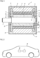
- Fig. 1 shows a sectional view of an embodiment of an electric machine 1 in the form of an asynchronous machine, comprising a housing 2, a stator 3 with a plurality of winding heads 4, 5 and a rotor 6, which is coupled to a shaft 7.
- the rotor 6 has a rotor core 10 comprising a laminated core 8 and a short-circuit cage 9.
- the short-circuit cage 9 comprises a multiplicity of rotor bars 11, which pass through the laminated core 8 substantially axially and are connected at their respective ends by short-circuit rings 12.
- the laminated core 8 is further penetrated by a plurality of axial cooling channels 13, which are flowed through by a cooling medium, such as oil, for dissipating heat from the interior of the rotor 6.
- the rotor 6 further has on a front side 14 on a cover plate 15 which is fixed to the rotor body 10.
- the attachment is presently realized on the short-circuit ring 12 by means not shown fastening means, such as screws and / or bolts, or by means of an adhesive or by welding.
- the cover plate 15 has a central through-opening 16 and a recess 17 formed on the side facing the rotor body 10, which causes a gradation of the cover plate 15.
- annular space 18 which is communicatively connected to the cooling channels 13.
- the annular space 18 thus forms an inwardly open radial groove.
- the cooling medium in the electric machine 1 can be introduced. It flows through gravity in the direction of a bottom side 21 of the electric machine 1 in the annular space 18 and is moved in the rotating operation of the rotor 6 by the centrifugal force to the radially outer boundary of the annular space 18. Because of the contact with the cooling medium, opposite attachment regions of the rotor body 10 and the cover plate 15 are sealed against each other by a sealant, which is preferably a liquid seal and / or an O-ring.
- the cooling medium collecting in the annular space 18 is conducted with increasing inflow into and through the cooling channels 13, which causes a continuous flow for cooling the rotor 6.
- the cooling medium After flowing through the cooling channels 13, the cooling medium leaves the cooling channels on the opposite end face 22 and, as a result of the rotational movement of the rotor 6, is thrown in the direction of the winding heads 4, which are likewise cooled by the impinging cooling medium. This then flows from the winding heads 4 or immediately after exiting the cooling channels 13 to the bottom side 21.
- the housing 2 further has a drain 23, through which the cooling medium leaves the interior of the electric machine 1. The leaked cooling medium is then fed to the realization of a cooling circuit an external cooler and then again the inlet 20.
- the radially outer boundary of the annular space 18 is completely formed by the rotor body 10, in particular by the short-circuit ring 12.
- the annular space is completely bounded radially on the outside by the stepped cover plate 15. This is useful when the electric machine 1 is a synchronous machine.
- the annular space 18 can be bounded radially on the outside completely or in sections by the laminated core 8.
- Fig. 2 shows a schematic diagram of an embodiment of a motor vehicle 24 with an electric machine 1 according to one of the preceding embodiments.
- the electric machine 1 is complete or partial drive of the motor vehicle 1 connected to a drive train 25 of the motor vehicle 24.
Landscapes
- Engineering & Computer Science (AREA)
- Power Engineering (AREA)
- Motor Or Generator Cooling System (AREA)
- Iron Core Of Rotating Electric Machines (AREA)
Abstract
Description
- Die Erfindung betrifft einen Rotor für eine elektrische Maschine, umfassend einen oder mehrere durch ein Kühlmedium durchströmbare Kühlkanäle, wobei an einer Stirnseite des Rotors ein axial nach innen und radial nach außen begrenzter, mit dem oder den Kühlkanälen kommunizierend verbundener Ringraum vorgesehen ist.
- Mit der wachsenden Bedeutung der Elektromobilität gewinnen Fragen der Rotorkühlung bei elektrischen Maschinen zunehmend an Relevanz. Dies gilt besonders für Maschinen mit großer Leistungsdichte, wie sie in der Automobilindustrie als Antriebsmotoren zum Einsatz kommen. Es wurde zur Abfuhr von Wärme aus dem Rotor bereits vorgeschlagen, eine Hohlwelle vorzusehen, in die mittels einer Lanze ein Kühlmedium eingeleitet wird. Durch die Fliehkraft bei der Bewegung des Rotors fließt das Kühlmedium entlang der Hohlwelle. Nachteilig ist daran, dass Dichtungen zum Ein- und/oder Ausleiten des Kühlmediums hohen mechanischen Belastungen standhalten müssen und daher sehr anspruchsvoll zu realisieren und fehleranfällig sind. Zudem entstehen erhebliche Reibungsverluste an der Dichtung.
- Um die Kühlung des Rotors über seine Welle zu vermeiden, wurde bereits vorgeschlagen, den Rotor mit einem oder mehreren Kühlkanälen auszustatten, durch die das Kühlmedium strömt. Das Kühlmedium kann dazu in einen Ringraum des Rotors eingeleitet werden, der kommunizierend mit dem oder einem jeweiligen Kühlkanal verbunden ist. Das sich im Ringraum sammelnde Kühlmedium wird dabei durch die Fliehkraft bei der Bewegung des Rotors axial durch den oder die Kühlkanäle geleitet.
-
DE 11 2008 000 535 T5 offenbart eine Kühlstruktur für elektrische Drehmaschinen, bei der Magnetaufnahmelöcher in einem Rotorkern derart vorgesehen sind, dass sie sich zwischen axialen Kernstirnflächen erstrecken, wobei Hohlräume jeweils in Berührung mit Permanentmagneten derart vorgesehen sind, dass sie sich zwischen den Kernstirnflächen erstrecken. Es ist ferner ein Rotorkühlflüssigkeitszufuhrkanal zum Zuführen von Kühlflüssigkeit zu einer Kernstirnfläche vorgesehen, wobei die von dem Rotorkühlflüssigkeitszufuhrkanal zugeführte Kühlflüssigkeit in die Hohlräume eingeleitet wird. An einem rotorseitigen Halter ist ein ringförmiger Reservoirbereich vorgesehen. - Die Integration eines Ringraums in einen Halter des Rotors erfordert jedoch eine komplexe Formgebung des Halters, was den Fertigungsaufwand eines solchen Rotors erheblich erhöht.
-
JP 2002 345 188 A -
TW 2014 21870 A - Der Erfindung liegt die Aufgabe zugrunde, eine fertigungstechnisch aufwandsärmere Möglichkeit zur Kühlung eines Rotors mit axialen Kühlkanälen anzugeben.
- Zur Lösung dieser Aufgabe ist erfindungsgemäß bei einem Rotor der eingangs genannten Art vorgesehen, dass eine an der Stirnseite befestigte, den Ringraum axial außen begrenzende Abdeckscheibe vorgesehen ist, welche eine mittige Durchgangsöffnung zum Einleiten des Kühlmediums in den Ringraum aufweist.
- Der Erfindung liegt die Überlegung zugrunde, die äußere Begrenzung des Ringraums durch eine ringförmige Abdeckscheibe zu realisieren, die als separates Bauelement des Rotors an der Stirnseite des Rotors befestigt ist. Gegenüber der Integration der äußeren Begrenzung des Ringraums in einen stirnseitigen Halter ermöglicht die Erfindung den Ringraum dadurch auszubilden, dass die Abdeckscheibe lediglich an einer den Ringraum zumindest abschnittsweise radial außen und axial innen begrenzenden Struktur des Rotors angebracht werden muss. Die fertigungstechnisch aufwändige Einformung auch der axial äußeren Begrenzungen des Ringraums in einen Halter oder eine andere Rotorkomponente kann so vermieden werden. Zudem kann die Abdeckscheibe aus einem anderen, beispielsweise leichteren oder elektromagnetisch verträglicheren, Material als die übrigen Rotorkomponenten gebildet werden.
- Der Ringraum des erfindungsgemäßen Rotors erstreckt sich insbesondere vollständig in Umfangsrichtung des Rotors. Der Ringraum kann somit auch als umlaufende Radialnut erachtet oder bezeichnet werden. Der oder ein jeweiliger Kühlkanal ist kommunizierend mit dem Ringraum verbunden, insbesondere mündet der oder jeder Kühlkanal in dem Ringraum bzw. der Ring-oder Radialnut. Wird das Kühlmedium folglich abdeckscheibenseitig durch die Durchgangsöffnung zum Ringraum hin eingeleitet, gelangt es im rotierenden Betrieb des Rotors mit ausreichender Drehzahl durch die Fliehkraft an die radial äußere Begrenzung des Ringraums und wird mit weiterem Zufluss des Kühlmediums in den oder einen jeweiligen Kühlkanal geleitet. Der Ringraum realisiert somit eine Fangrinne für das in ihn eingeleitete Kühlmedium.
- Die Abdeckscheibe ist üblicherweise flach, das heißt ihre axiale Ausdehnung in befestigter Stellung ist geringer als ihr Durchmesser. Zwischen einer den Rotor durchsetzenden Welle und dem Außendurchmesser der Durchgangsöffnung ist zweckmäßigerweise ein konzentrischer Freiraum zum Einleiten des Kühlmediums vorgesehen. Eine Rotorkomponente, an dem die Abdeckscheibe befestigt ist, kann auch als Rotorkörper bezeichnet werden. Mithin ist die Abdeckscheibe bezüglich des Rotorkörpers ein separates Anbauteil des Rotors. Der Rotorkörper und die Abdeckscheibe können materialverschieden sein. Durch den Rotorkörper kann der Ringraum axial innen und zumindest abschnittsweise radial außen begrenzt sein.
- Bei dem erfindungsgemäßen Rotor liegt der Außendurchmesser der Durchgangsöffnung bevorzugt weiter innen als der oder die Kühlkanäle. Mit anderen Worten erstreckt sich der Innendurchmesser der Abdeckscheibe, der die Durchgangsöffnung begrenzt, radial weiter nach innen als die radial innerste Stelle der stirnseitigen Öffnung des oder eines jeweiligen Kühlkanals, positioniert ist. Dadurch wird gewährleistet, dass ein ausreichendes Volumen zur Aufnahme des Kühlmediums durch den Ringraum gegeben ist.
- Gemäß einer bevorzugten Ausgestaltung des erfindungsgemäßen Rotors ist die Abdeckscheibe kraftschlüssig, insbesondere mittels wenigstens einer Schraube und/oder wenigstens eines Bolzens und/oder mittels eines Klebstoffs, und/oder stoffschlüssig, insbesondere mittels Schweißens, am Rotor befestigt. Die Schraube und/oder der Bolzen können dementsprechend in den Rotorkörper eindringen. Es ist ferner zweckmäßig, wenn die Abdeckscheibe in ihrem Befestigungsabschnitt mittels eines Dichtmittels, insbesondere einer Flüssigdichtung und/oder eines O-Rings, abgedichtet ist. Dem Befestigungsabschnitt der Abdeckscheibe kann dementsprechend ein rotorkörperseitiger Befestigungsabschnitt gegenüberliegen, wobei zwischen den Befestigungsabschnitten das Dichtmittel angeordnet ist. Das Dichtmittel kann auch durch den die Abdeckscheibe befestigenden Klebstoff realisiert sein.
- Neben der axial äußeren Begrenzung des Ringraums durch die Abdeckscheibe ist es möglich, dass die Abdeckscheibe an der zum Ringraum weisenden Seite eine konzentrisch zur Durchgangsöffnung ausgebildete Eintiefung aufweist, deren Außendurchmesser den Ringraum zumindest abschnittsweise radial nach außen begrenzt. Die Abdeckscheibe kann mit anderen Worten eine Stufe aufweisen, durch deren Umfangsfläche der Ringraum zumindest abschnittsweise radial nach außen begrenzt ist. Es ist auch denkbar, dass der Ringraum durch den Außendurchmesser der Eintiefung bzw. die Umfangsfläche der Stufe vollständig radial nach außen begrenzt ist.
- Insbesondere im Hinblick auf eine Verwendung des Rotors in einer Asynchronmaschine wird es bevorzugt, wenn ein Kurzschlusskäfig vorgesehen ist. Dieser kann mehrere von der Stirnseite zur gegenüberliegenden Stirnseite verlaufend angeordnete Läuferstäbe aufweisen. Typischerweise weist der Kurzschlusskäfig zumindest an der Stirnseite, an welcher die Abdeckscheibe befestigt ist, einen Kurzschlussring auf. Die Kühlkanäle verlaufen zweckmäßigerweise weiter radial innen als die radiale Innenwandung des Kurzschlussrings. Der Kurzschlusskäfig ist Teil des Rotorkörpers.
- Besonders bevorzugt ist der Ringraum zumindest abschnittsweise radial außen durch den Kurzschlusskäfig, insbesondere durch seinen Kurzschlussring, begrenzt. Der Kurzschlusskäfig kann dadurch zur Begrenzung des Ringraums mitverwendet werden. Das Kühlmedium kann sich dadurch vorteilhafterweise auf dem begrenzenden Abschnitt des Kurzschlusskäfigs, beispielsweise dem Innendurchmesser des Kurzschlussrings, sammeln, bevor es den oder die Kühlkanäle durchströmt. Der Ringraum kann auch vollständig axial außen durch den Kurzschlusskäfig, insbesondere den Kurzschlussring, begrenzt sein. Alternativ oder zusätzlich kann die Abdeckscheibe an dem Kurzschlusskäfig, insbesondere an dem Kurzschlussring, befestigt sein.
- Bei dem erfindungsgemäßen Rotor ist zweckmäßigerweise ein Blechpaket vorgesehen. Der oder die Kühlkanäle durchsetzen üblicherweise das Blechpaket. Wenn ein Kurzschlusskäfig vorgesehen ist, durchsetzen dessen Läuferstäbe typischerweise das Blechpaket. Das Blechpaket ist ebenfalls Teil des Rotorkörpers. Bevorzugt ist der Ringraum axial innen durch das Blechpaket begrenzt. Es kann alternativ oder zusätzlich auch vorgesehen sein, dass der Ringraum durch das Blechpaket zumindest abschnittsweise radial außen begrenzt ist. Dies gilt insbesondere, wenn kein Kurzschlusskäfig vorgesehen ist.
- Daneben wird die eingangs genannte Aufgabe erfindungsgemäß gelöst durch eine elektrische Maschine, insbesondere Asynchronmaschine, für ein Kraftfahrzeug, umfassend einen erfindungsgemäßen Rotor. Sämtliche Ausführungen zum erfindungsgemäßen Rotor lassen sich analog auf die erfindungsgemäße elektrische Maschine übertragen, so dass auch mit dieser die zuvor genannten Vorteile erzielt werden können.
- Bevorzugt ist bei der erfindungsgemäßen Maschine ein bezüglich der Drehbewegung des Rotors stationär angeordneter Zulauf vorgesehen, mittels welchem das Kühlmedium in den Ringraum einbringbar ist. Der Zulauf kann beispielsweise durch ein Rohr oder einen Schlauch ausgebildet sein. Der Zulauf kann sich von außerhalb der Durchgangsöffnung in Richtung der Stirnseite, an welcher die Abdeckscheibe befestigt ist, erstrecken. Weiterhin kann der Zulauf die Durchgangsöffnung in axialer Richtung überragen oder bündig mit der dem Ringraum zugewandten Seite der Durchgangsöffnung abschließen. Der Zulauf ist bevorzugt an einem der Bodenseite der elektrischen Maschine zugewandten Bereich der Abdeckscheibe angeordnet, so dass das Kühlmedium durch die Schwerkraft in den Ringraum fließen kann.
- Zweckmäßigerweise ist ferner ein Gehäuse mit einem Ablauf vorgesehen, durch welchen das Kühlmedium nach dem Durchströmen des Rotors aus dem Inneren des Gehäuses abführbar ist. Der Ablauf ist bevorzugt der Abdeckscheibe gegenüberliegend und/oder bodenseitig angeordnet. Das durch den Ablauf austretende Kühlmedium kann zu einem externen Kühler abgeleitet und dort rückgekühlt werden.
- Besonders bevorzugt ist ein Stator mit wenigstens einem Wickelkopf vorgesehen, welcher derart angeordnet ist, dass das Kühlmedium im rotierenden Betrieb des Rotors nach dem Durchströmen des Rotors auf den Wickelkopf auftrifft. Die Kühlung der elektrischen Maschine kann so aufwandsarm von einer rotorinternen Kühlung auf eine zusätzliche Kühlung des oder eines jeweiligen Wickelkopfes erweitert werden. Im Anschluss an das Auftreffen auf den Wickelkopf kann das Kühlmedium aus dem Ablauf austreten.
- Bei der erfindungsgemäßen Maschine ist es außerdem von Vorteil, wenn wenigstens eine das Kühlmedium führende Einleitung und/oder wenigstens eine das Kühlmedium abgebende Düse vorgesehen ist oder sind, mittels welcher oder welchen wenigstens eine zu kühlende Maschinenkomponente mit dem Kühlmedium beaufschlagbar ist. Die oder eine jeweilige Düse kann beispielsweise vom Zulauf ausgehen und/oder auf die oder eine Maschinenkomponente gerichtet sein. Dadurch lassen sich gezielt weitere thermisch belastete Stellen der elektrischen Maschine kühlen.
- Schließlich wird die eingangs genannte Aufgabe erfindungsgemäß gelöst durch ein Kraftfahrzeug, umfassend eine erfindungsgemäße elektrische Maschine. Die elektrische Maschine ist bevorzugt zum teilweisen oder vollständigen elektrischen Antrieb des Kraftfahrzeugs eingerichtet. Sämtliche Ausführung zum erfindungsgemäßen Rotor und zur erfindungsgemäßen elektrischen Maschine lassen sich analog auf das erfindungsgemäße Kraftfahrzeug übertragen, so dass auch mit diesem die zuvor genannten Vorteile erzielt werden können.
- Weitere Vorteile und Einzelheiten der Erfindung ergeben sich aus den im Folgenden beschriebenen Ausführungsbeispielen sowie anhand der Zeichnung. Diese sind schematische Darstellungen und zeigen:
- Fig. 1
- eine Schnittdarstellung eines Ausführungsbeispiels einer erfindungsgemäßen elektrischen Maschine; und
- Fig. 2
- eine Prinzipskizze eines Ausführungsbeispiels eines erfindungsgemäßen Kraftfahrzeugs.
-
Fig. 1 zeigt eine Schnittdarstellung eines Ausführungsbeispiels einer elektrischen Maschine 1 in Form einer Asynchronmaschine, umfassend ein Gehäuse 2, einen Stator 3 mit mehreren Wickelköpfen 4, 5 und einen Rotor 6, welcher mit einer Welle 7 gekoppelt ist. - Der Rotor 6 weist einen ein Blechpaket 8 und einen Kurzschlusskäfig 9 umfassenden Rotorkörper 10 auf. Der Kurzschlusskäfig 9 umfasst eine Vielzahl von Läuferstäben 11, die das Blechpaket 8 im Wesentlichen axial durchsetzen und an ihren jeweiligen Enden durch Kurzschlussringe 12 verbunden sind. Das Blechpaket 8 ist ferner von einer Vielzahl axialer Kühlkanäle 13 durchsetzt, welche von einem Kühlmedium, beispielsweise Öl, zur Abfuhr von Wärme aus dem Inneren des Rotors 6 durchströmbar sind.
- Der Rotor 6 weist ferner an einer Stirnseite 14 eine Abdeckscheibe 15 auf, die an dem Rotorkörper 10 befestigt ist. Die Befestigung ist vorliegend am Kurzschlussring 12 mittels nicht gezeigter Befestigungsmittel, beispielsweise Schrauben und/oder Bolzen, oder mittels eines Klebstoffs oder durch Schweißen realisiert. Die Abdeckscheibe 15 weist eine mittige Durchgangsöffnung 16 sowie eine an der dem Rotorkörper 10 zugewandten Seite ausgebildete Eintiefung 17 auf, die eine Stufung der Abdeckscheibe 15 bewirkt. Auf diese Weise ist ein axial innen durch das Blechpaket 8, radial außen jeweils abschnittsweise durch die Innenumfangswand des Kurzschlussrings 12 und die Außenumfangswand der Eintiefung 17 und axial außen durch die Abdeckscheibe 15 begrenzter Ringraum 18 gebildet, der kommunizierend mit den Kühlkanälen 13 verbunden ist. Der Ringraum 18 bildet also eine nach innen offene Radialnut.
- Mittels eines einen Deckel 19 des Gehäuses 2 durchdringenden Zulaufs 20, beispielsweis in Form eines Rohres oder Schlauchs, ist das Kühlmedium in die elektrische Maschine 1 einleitbar. Es fließt dabei durch die Schwerkraft in Richtung einer Bodenseite 21 der elektrischen Maschine 1 in den Ringraum 18 und wird im rotierenden Betrieb des Rotors 6 durch die Fliehkraft an die radial äußere Begrenzung des Ringraums 18 bewegt. Wegen des Kontakts mit dem Kühlmedium sind gegenüberliegende Befestigungsbereiche des Rotorkörpers 10 und der Abdeckscheibe 15 durch ein Dichtmittel, welches bevorzugt eine Flüssigdichtung und/oder ein O-Ring ist, gegeneinander abgedichtet. Das sich im Ringraum 18 sammelnde Kühlmedium wird mit zunehmendem Zufluss in und durch die Kühlkanäle 13 geleitet, was einen kontinuierlichen Strom zur Kühlung des Rotors 6 bewirkt.
- Nach dem Durchströmen der Kühlkanäle 13 verlässt das Kühlmedium an der gegenüberliegenden Stirnseite 22 die Kühlkanäle und wird infolge der Drehbewegung des Rotors 6 in Richtung der Wickelköpfe 4 geschleudert, welche durch das auftreffende Kühlmedium ebenfalls gekühlt werden. Dieses fließt dann von den Wickelköpfen 4 oder unmittelbar nach Austritt aus den Kühlkanälen 13 zur Bodenseite 21. Das Gehäuse 2 weist ferner einen Ablauf 23 auf, durch welchen das Kühlmedium das Innere der elektrischen Maschine 1 verlässt. Das ausgetretene Kühlmedium wird dann zur Realisierung eines Kühlkreislaufs einem externen Kühler und anschließend erneut dem Zulauf 20 zugeführt.
- Darüber hinaus sind weitere nicht gezeigte Einleitungen des Kühlmediums in das Innere der elektrischen Maschine 1 zur Kühlung weiterer thermisch belasteter Bereiche vorgesehen. An den Einleitungen oder am Zulauf 20 können auf diese Bereiche gerichtete Düsen vorgesehen sein, aus welchen das Kühlmedium austritt und entsprechende thermisch belastete Maschinenkomponenten beaufschlagt. Ein Abfluss des so abgegebenen Kühlmediums wird dabei ebenfalls durch den bodenseitigen Ablauf 23 ermöglicht.
- Gemäß einem weiteren Ausführungsbeispiel wird die radial äußere Begrenzung des Ringraums 18 vollständig durch den Rotorkörper 10, insbesondere durch den Kurzschlussring 12 gebildet. Bei einem alternativen Ausführungsbeispiels, bei dem ganz auf den Kurzschlusskäfig 9 verzichtet werden kann, wird der Ringraum radial außen vollständig durch die gestufte Abdeckscheibe 15 begrenzt. Dies ist zweckmäßig, wenn die elektrische Maschine 1 eine Synchronmaschine ist. Im Rahmen eines weiteren Ausführungsbeispiels kann der Ringraum 18 radial außen vollständig oder abschnittsweise durch das Blechpaket 8 begrenzt sein.
-
Fig. 2 zeigt eine Prinzipskizze eines Ausführungsbeispiels eines Kraftfahrzeugs 24 mit einer elektrischen Maschine 1 gemäß einem der vorangegangenen Ausführungsbeispiele. Die elektrische Maschine 1 ist zum vollständigen oder teilweisen Antrieb des Kraftfahrzeug 1 mit einem Antriebstrang 25 des Kraftfahrzeugs 24 verbunden.
Claims (13)
- Rotor für eine elektrische Maschine (1), umfassend einen oder mehrere durch ein Kühlmedium durchströmbare Kühlkanäle (13), wobei an einer Stirnseite (14) des Rotors (6) ein axial nach innen und radial nach außen begrenzter, mit dem oder den Kühlkanälen (13) kommunizierend verbundener Ringraum (18) vorgesehen ist,
dadurch gekennzeichnet,
dass eine an der Stirnseite (14) befestigte, den Ringraum (18) axial außen begrenzende Abdeckscheibe (15) vorgesehen ist, welche eine mittige Durchgangsöffnung (16) zum Einleiten des Kühlmediums in den Ringraum (18) aufweist. - Rotor nach Anspruch 1,
dadurch gekennzeichnet,
dass der Außendurchmesser der Durchgangsöffnung (16) weiter innen liegt als der oder die Kühlkanäle (13). - Rotor nach Anspruch 1 oder 2,
dadurch gekennzeichnet,
dass die Abdeckscheibe (15) kraftschlüssig, insbesondere mittels wenigstens einer Schraube und/oder wenigstens eines Bolzens und/oder mittels eines Klebstoffs, und/oder stoffschlüssig, insbesondere mittels Schweißens, am Rotor (6) befestigt ist. - Rotor nach einem der vorhergehenden Ansprüche,
dadurch gekennzeichnet,
dass die Abdeckscheibe (15) in ihrem Befestigungsabschnitt mittels eines Dichtmittels, insbesondere einer Flüssigdichtung, abgedichtet ist. - Rotor nach einem der vorhergehenden Ansprüche,
dadurch gekennzeichnet,
dass die Abdeckscheibe (15) an der zum Ringraum (18) weisenden Seite eine konzentrisch zur Durchgangsöffnung (16) ausgebildete Eintiefung (17) aufweist, deren Außendurchmesser den Ringraum (18) zumindest abschnittsweise radial nach außen begrenzt. - Rotor nach einem der vorhergehenden Ansprüche,
dadurch gekennzeichnet,
dass ein Kurzschlusskäfig (9) vorgesehen ist, durch welchen der Ringraum (18) zumindest abschnittsweise radial außen begrenzt ist und/oder an welchem die Abdeckscheibe (15) befestigt ist. - Rotor nach einem der vorhergehenden Ansprüche,
dadurch gekennzeichnet,
dass ein Blechpaket (8) vorgesehen ist, durch welches der Ringraum (18) axial innen und/oder zumindest abschnittsweise radial außen begrenzt ist und/oder welches von dem oder den Kühlkanälen (13) durchsetzt ist. - Elektrische Maschine, insbesondere Asynchronmaschine, für ein Kraftfahrzeug (24), umfassend einen Rotor (6) nach einem der vorhergehenden Ansprüche.
- Elektrische Maschine nach Anspruch 8,
dadurch gekennzeichnet,
dass ein bezüglich der Drehbewegung des Rotors (6) stationär angeordneter Zulauf (20) vorgesehen ist, mittels welchem das Kühlmedium in den Ringraum (18) einbringbar ist. - Elektrische Maschine nach Anspruch 8 oder 9,
dadurch gekennzeichnet,
dass ein Gehäuse (2) mit einem Ablauf (23) vorgesehen ist, durch welchen das Kühlmedium nach dem Durchströmen des Rotors (6) aus dem Inneren des Gehäuses (2) abführbar ist. - Elektrische Maschine nach einem der Ansprüche 8 bis 10,
dadurch gekennzeichnet,
dass ein Stator (3) mit wenigstens einem Wickelkopf (4) vorgesehen ist, welcher derart angeordnet ist, dass das Kühlmedium im rotierenden Betrieb des Rotors (6) nach dem Durchströmen des Rotors (6) auf dem Wickelkopf (4) auftrifft. - Elektrische Maschine nach einem der Ansprüche 8 bis 11,
dadurch gekennzeichnet,
dass wenigstens eine das Kühlmedium führende Einleitung und/oder wenigstens eine das Kühlmedium abgebende Düse vorgesehen ist oder sind, mittels welcher oder welchen wenigstens eine zu kühlende Maschinenkomponente mit dem Kühlmedium beaufschlagbar ist. - Kraftfahrzeug, umfassend eine elektrische Maschine (1) nach einem der Ansprüche 8 bis 12.
Applications Claiming Priority (1)
| Application Number | Priority Date | Filing Date | Title |
|---|---|---|---|
| DE102017201390.7A DE102017201390A1 (de) | 2017-01-30 | 2017-01-30 | Rotor für eine elektrische Maschine, elektrische Maschine, insbesondere Asynchronmaschine, für ein Kraftfahrzeug und Kraftfahrzeug |
Publications (2)
| Publication Number | Publication Date |
|---|---|
| EP3355444A1 true EP3355444A1 (de) | 2018-08-01 |
| EP3355444B1 EP3355444B1 (de) | 2022-01-12 |
Family
ID=60484271
Family Applications (1)
| Application Number | Title | Priority Date | Filing Date |
|---|---|---|---|
| EP17204307.7A Active EP3355444B1 (de) | 2017-01-30 | 2017-11-29 | Rotor für eine elektrische maschine, elektrische maschine, insbesondere asynchronmaschine, für ein kraftfahrzeug und kraftfahrzeug |
Country Status (4)
| Country | Link |
|---|---|
| US (1) | US10601272B2 (de) |
| EP (1) | EP3355444B1 (de) |
| CN (1) | CN108377048B (de) |
| DE (1) | DE102017201390A1 (de) |
Families Citing this family (3)
| Publication number | Priority date | Publication date | Assignee | Title |
|---|---|---|---|---|
| DE102020107376B4 (de) | 2020-03-18 | 2021-11-25 | Schaeffler Technologies AG & Co. KG | Kühlvorrichtung mit einem durch einen Kühlmittelstrom rotatorisch antreibbaren Verteilerring; sowie elektrische Antriebseinheit |
| AT525415B1 (de) * | 2021-09-10 | 2024-09-15 | Miba Emobility Gmbh | Elektrische Maschine und Antriebseinheit mit einer solchen elektrischen Maschine |
| DE102021211303A1 (de) | 2021-10-07 | 2023-04-13 | Volkswagen Aktiengesellschaft | Vorrichtung zur Verteilung von Kühlmedium in einem Wickelkopf einer elektrischen Maschine |
Citations (11)
| Publication number | Priority date | Publication date | Assignee | Title |
|---|---|---|---|---|
| JPS4857605U (de) * | 1971-11-04 | 1973-07-23 | ||
| JPS497405U (de) * | 1972-04-24 | 1974-01-22 | ||
| JPS51110605A (ja) * | 1975-03-24 | 1976-09-30 | Hitachi Ltd | Arumikyasutokaitenshi |
| JPS51160106U (de) * | 1975-06-16 | 1976-12-20 | ||
| JPS60183550U (ja) * | 1984-05-17 | 1985-12-05 | 芝浦メカトロニクス株式会社 | 水中モ−タの回転子冷却機構 |
| JPS637978U (de) * | 1986-07-01 | 1988-01-19 | ||
| JPH0993868A (ja) * | 1995-09-28 | 1997-04-04 | Toyo Electric Mfg Co Ltd | 車両用主電動機 |
| DE102004049795A1 (de) * | 2004-04-08 | 2005-11-10 | Deere & Company, Moline | Kühlvorrichtung für eine mit einer Kühlflüssigkeit kühlbaren elektrischen Maschine |
| JP2011142788A (ja) * | 2010-01-08 | 2011-07-21 | Toyota Motor Corp | 電動機の冷却構造 |
| JP2016049005A (ja) * | 2014-08-28 | 2016-04-07 | 株式会社小松製作所 | 電動機 |
| DE102015224034A1 (de) * | 2015-05-20 | 2016-11-24 | Hyundai Motor Company | Motor mit einer Kühlstruktur |
Family Cites Families (25)
| Publication number | Priority date | Publication date | Assignee | Title |
|---|---|---|---|---|
| US3241331A (en) | 1963-04-17 | 1966-03-22 | Carrier Corp | Apparatus for and method of motor cooling |
| JPS5428562B2 (de) | 1971-12-29 | 1979-09-18 | ||
| JPS533605B2 (de) | 1972-07-10 | 1978-02-08 | ||
| JPS533605A (en) * | 1976-06-30 | 1978-01-13 | Toshiba Corp | Electric rotary machine of liquid cool type |
| DE4443427C2 (de) | 1994-12-06 | 2002-04-18 | Siemens Ag | Elektrische Maschine |
| DE19849094C2 (de) | 1998-10-24 | 2003-04-10 | Prec Motors Deutsche Minebea G | Spindelmotor mit Magnetdichtung |
| JP4715028B2 (ja) | 2001-05-14 | 2011-07-06 | 日産自動車株式会社 | 回転電機 |
| CN101124710B (zh) * | 2005-09-28 | 2010-10-06 | 丰田自动车株式会社 | 旋转电机的转子 |
| DE102006012001A1 (de) | 2006-03-16 | 2007-09-20 | Schaeffler Kg | Hochgeschwindigkeitslager, insbesondere direktgeschmiertes Spindellager für eine Werkzeugmaschine |
| JP4757238B2 (ja) | 2007-07-13 | 2011-08-24 | アイシン・エィ・ダブリュ株式会社 | 回転電機の冷却構造及び冷却方法 |
| JP4363479B2 (ja) * | 2007-11-09 | 2009-11-11 | トヨタ自動車株式会社 | 回転電機および駆動装置 |
| JP5167868B2 (ja) | 2008-03-03 | 2013-03-21 | 日産自動車株式会社 | 電動機 |
| US8159094B2 (en) * | 2009-03-11 | 2012-04-17 | Nidec Motor Corporation | Electric motor having fluid circulation system and methods for cooling an electric motor |
| EP2230751A1 (de) * | 2009-03-16 | 2010-09-22 | ABB Oy | System und Verfahren um eine dynamoelektrische Maschine abzukühlen |
| JP5490103B2 (ja) | 2009-04-17 | 2014-05-14 | 株式会社日本自動車部品総合研究所 | 回転電機 |
| JP5483094B2 (ja) | 2010-05-31 | 2014-05-07 | アイシン精機株式会社 | 回転電機のロータ |
| JP5598378B2 (ja) * | 2011-02-28 | 2014-10-01 | アイシン・エィ・ダブリュ株式会社 | シャフト |
| JP2012235546A (ja) | 2011-04-28 | 2012-11-29 | Nippon Soken Inc | ロータおよび回転電機 |
| JP2013258889A (ja) | 2012-05-17 | 2013-12-26 | Toyota Industries Corp | 誘導電動機 |
| US8896167B2 (en) * | 2012-05-25 | 2014-11-25 | Deere & Company | Electric machine rotor cooling method |
| US8970075B2 (en) | 2012-08-08 | 2015-03-03 | Ac Propulsion, Inc. | Liquid cooled electric motor |
| JP5469719B1 (ja) * | 2012-09-25 | 2014-04-16 | 株式会社小松製作所 | 電動機 |
| TW201421870A (zh) | 2012-11-16 | 2014-06-01 | yong-li Chen | 油冷式馬達 |
| JP5991545B2 (ja) * | 2013-11-15 | 2016-09-14 | 株式会社デンソー | 回転電機のロータ及びそのロータを備えた回転電機 |
| JP5959687B1 (ja) * | 2015-04-28 | 2016-08-02 | 三菱電機株式会社 | 回転電機 |
-
2017
- 2017-01-30 DE DE102017201390.7A patent/DE102017201390A1/de active Pending
- 2017-11-29 EP EP17204307.7A patent/EP3355444B1/de active Active
- 2017-12-21 US US15/850,039 patent/US10601272B2/en active Active
-
2018
- 2018-01-29 CN CN201810083345.6A patent/CN108377048B/zh active Active
Patent Citations (11)
| Publication number | Priority date | Publication date | Assignee | Title |
|---|---|---|---|---|
| JPS4857605U (de) * | 1971-11-04 | 1973-07-23 | ||
| JPS497405U (de) * | 1972-04-24 | 1974-01-22 | ||
| JPS51110605A (ja) * | 1975-03-24 | 1976-09-30 | Hitachi Ltd | Arumikyasutokaitenshi |
| JPS51160106U (de) * | 1975-06-16 | 1976-12-20 | ||
| JPS60183550U (ja) * | 1984-05-17 | 1985-12-05 | 芝浦メカトロニクス株式会社 | 水中モ−タの回転子冷却機構 |
| JPS637978U (de) * | 1986-07-01 | 1988-01-19 | ||
| JPH0993868A (ja) * | 1995-09-28 | 1997-04-04 | Toyo Electric Mfg Co Ltd | 車両用主電動機 |
| DE102004049795A1 (de) * | 2004-04-08 | 2005-11-10 | Deere & Company, Moline | Kühlvorrichtung für eine mit einer Kühlflüssigkeit kühlbaren elektrischen Maschine |
| JP2011142788A (ja) * | 2010-01-08 | 2011-07-21 | Toyota Motor Corp | 電動機の冷却構造 |
| JP2016049005A (ja) * | 2014-08-28 | 2016-04-07 | 株式会社小松製作所 | 電動機 |
| DE102015224034A1 (de) * | 2015-05-20 | 2016-11-24 | Hyundai Motor Company | Motor mit einer Kühlstruktur |
Also Published As
| Publication number | Publication date |
|---|---|
| CN108377048A (zh) | 2018-08-07 |
| EP3355444B1 (de) | 2022-01-12 |
| DE102017201390A1 (de) | 2018-08-02 |
| US10601272B2 (en) | 2020-03-24 |
| CN108377048B (zh) | 2020-10-30 |
| US20180219443A1 (en) | 2018-08-02 |
Similar Documents
| Publication | Publication Date | Title |
|---|---|---|
| DE102014018223A1 (de) | Elektrische Maschine, insbesondere Asynchronmaschine | |
| WO2022233531A1 (de) | Rotoreinrichtung für eine elektrische maschine | |
| DE102017211317A1 (de) | Stator einer elektrischen Maschine sowie Kühlvorrichtung hierfür | |
| DE102016209173A1 (de) | Rotor für eine elektrische Maschine | |
| DE102013020331A1 (de) | Elektrische Maschine, insbesondere Asynchronmaschine | |
| EP3202018A1 (de) | Elektrische maschine mit kühlung | |
| EP0623988B1 (de) | Elektrische Maschine | |
| DE102015011863B4 (de) | Elektrische Maschine | |
| DE102015205724A1 (de) | Kühlsystem eines elektrischen Antriebes | |
| DE102011056007A1 (de) | Kühlsystem für eine rotierende elektrische Maschine höchster Leistungsdichte | |
| DE102022213027A1 (de) | Rotor und elektrische Maschine | |
| DE4115273C1 (de) | ||
| WO2015018575A1 (de) | Kühlung für eine hybridantriebsanordnung | |
| DE102019217510A1 (de) | Rotor, Elektromaschine und Kraftfahrzeug | |
| EP1649578B1 (de) | Elektrische Maschine mit Kühlmittelführungskanal sowie entsprechendes Kühlverfahren | |
| EP3355444B1 (de) | Rotor für eine elektrische maschine, elektrische maschine, insbesondere asynchronmaschine, für ein kraftfahrzeug und kraftfahrzeug | |
| DE102011052085A1 (de) | Kühlung einer permanent erregten Synchronmaschine | |
| WO2024027988A1 (de) | Elektrische maschine | |
| DE102016216083A1 (de) | Fluidgekühlte elektrische Maschine | |
| DE102014207468A1 (de) | Kühlung für einen Wickelkopf einer E-Maschine | |
| DE102023117610B3 (de) | Rotor eines Elektromotors mit Statorkühlung | |
| DE102011084083A1 (de) | Rotorläufer für einen Elektromotor | |
| DE102017211346B4 (de) | Elektrische Maschine | |
| EP3200327B1 (de) | Luftgekühlte elektrische maschine | |
| DE102008001618A1 (de) | Elektrische Maschine mit einer Kühleinrichtung |
Legal Events
| Date | Code | Title | Description |
|---|---|---|---|
| PUAI | Public reference made under article 153(3) epc to a published international application that has entered the european phase |
Free format text: ORIGINAL CODE: 0009012 |
|
| STAA | Information on the status of an ep patent application or granted ep patent |
Free format text: STATUS: THE APPLICATION HAS BEEN PUBLISHED |
|
| AK | Designated contracting states |
Kind code of ref document: A1 Designated state(s): AL AT BE BG CH CY CZ DE DK EE ES FI FR GB GR HR HU IE IS IT LI LT LU LV MC MK MT NL NO PL PT RO RS SE SI SK SM TR |
|
| AX | Request for extension of the european patent |
Extension state: BA ME |
|
| STAA | Information on the status of an ep patent application or granted ep patent |
Free format text: STATUS: REQUEST FOR EXAMINATION WAS MADE |
|
| 17P | Request for examination filed |
Effective date: 20190201 |
|
| RBV | Designated contracting states (corrected) |
Designated state(s): AL AT BE BG CH CY CZ DE DK EE ES FI FR GB GR HR HU IE IS IT LI LT LU LV MC MK MT NL NO PL PT RO RS SE SI SK SM TR |
|
| STAA | Information on the status of an ep patent application or granted ep patent |
Free format text: STATUS: EXAMINATION IS IN PROGRESS |
|
| 17Q | First examination report despatched |
Effective date: 20201215 |
|
| GRAP | Despatch of communication of intention to grant a patent |
Free format text: ORIGINAL CODE: EPIDOSNIGR1 |
|
| STAA | Information on the status of an ep patent application or granted ep patent |
Free format text: STATUS: GRANT OF PATENT IS INTENDED |
|
| INTG | Intention to grant announced |
Effective date: 20211005 |
|
| GRAS | Grant fee paid |
Free format text: ORIGINAL CODE: EPIDOSNIGR3 |
|
| GRAA | (expected) grant |
Free format text: ORIGINAL CODE: 0009210 |
|
| STAA | Information on the status of an ep patent application or granted ep patent |
Free format text: STATUS: THE PATENT HAS BEEN GRANTED |
|
| AK | Designated contracting states |
Kind code of ref document: B1 Designated state(s): AL AT BE BG CH CY CZ DE DK EE ES FI FR GB GR HR HU IE IS IT LI LT LU LV MC MK MT NL NO PL PT RO RS SE SI SK SM TR |
|
| REG | Reference to a national code |
Ref country code: GB Ref legal event code: FG4D Free format text: NOT ENGLISH |
|
| REG | Reference to a national code |
Ref country code: CH Ref legal event code: EP |
|
| REG | Reference to a national code |
Ref country code: DE Ref legal event code: R096 Ref document number: 502017012437 Country of ref document: DE |
|
| REG | Reference to a national code |
Ref country code: IE Ref legal event code: FG4D Free format text: LANGUAGE OF EP DOCUMENT: GERMAN |
|
| REG | Reference to a national code |
Ref country code: AT Ref legal event code: REF Ref document number: 1463025 Country of ref document: AT Kind code of ref document: T Effective date: 20220215 |
|
| REG | Reference to a national code |
Ref country code: LT Ref legal event code: MG9D |
|
| REG | Reference to a national code |
Ref country code: NL Ref legal event code: MP Effective date: 20220112 |
|
| PG25 | Lapsed in a contracting state [announced via postgrant information from national office to epo] |
Ref country code: NL Free format text: LAPSE BECAUSE OF FAILURE TO SUBMIT A TRANSLATION OF THE DESCRIPTION OR TO PAY THE FEE WITHIN THE PRESCRIBED TIME-LIMIT Effective date: 20220112 |
|
| PG25 | Lapsed in a contracting state [announced via postgrant information from national office to epo] |
Ref country code: SE Free format text: LAPSE BECAUSE OF FAILURE TO SUBMIT A TRANSLATION OF THE DESCRIPTION OR TO PAY THE FEE WITHIN THE PRESCRIBED TIME-LIMIT Effective date: 20220112 Ref country code: RS Free format text: LAPSE BECAUSE OF FAILURE TO SUBMIT A TRANSLATION OF THE DESCRIPTION OR TO PAY THE FEE WITHIN THE PRESCRIBED TIME-LIMIT Effective date: 20220112 Ref country code: PT Free format text: LAPSE BECAUSE OF FAILURE TO SUBMIT A TRANSLATION OF THE DESCRIPTION OR TO PAY THE FEE WITHIN THE PRESCRIBED TIME-LIMIT Effective date: 20220512 Ref country code: NO Free format text: LAPSE BECAUSE OF FAILURE TO SUBMIT A TRANSLATION OF THE DESCRIPTION OR TO PAY THE FEE WITHIN THE PRESCRIBED TIME-LIMIT Effective date: 20220412 Ref country code: LT Free format text: LAPSE BECAUSE OF FAILURE TO SUBMIT A TRANSLATION OF THE DESCRIPTION OR TO PAY THE FEE WITHIN THE PRESCRIBED TIME-LIMIT Effective date: 20220112 Ref country code: HR Free format text: LAPSE BECAUSE OF FAILURE TO SUBMIT A TRANSLATION OF THE DESCRIPTION OR TO PAY THE FEE WITHIN THE PRESCRIBED TIME-LIMIT Effective date: 20220112 Ref country code: ES Free format text: LAPSE BECAUSE OF FAILURE TO SUBMIT A TRANSLATION OF THE DESCRIPTION OR TO PAY THE FEE WITHIN THE PRESCRIBED TIME-LIMIT Effective date: 20220112 Ref country code: BG Free format text: LAPSE BECAUSE OF FAILURE TO SUBMIT A TRANSLATION OF THE DESCRIPTION OR TO PAY THE FEE WITHIN THE PRESCRIBED TIME-LIMIT Effective date: 20220412 |
|
| PG25 | Lapsed in a contracting state [announced via postgrant information from national office to epo] |
Ref country code: PL Free format text: LAPSE BECAUSE OF FAILURE TO SUBMIT A TRANSLATION OF THE DESCRIPTION OR TO PAY THE FEE WITHIN THE PRESCRIBED TIME-LIMIT Effective date: 20220112 Ref country code: LV Free format text: LAPSE BECAUSE OF FAILURE TO SUBMIT A TRANSLATION OF THE DESCRIPTION OR TO PAY THE FEE WITHIN THE PRESCRIBED TIME-LIMIT Effective date: 20220112 Ref country code: GR Free format text: LAPSE BECAUSE OF FAILURE TO SUBMIT A TRANSLATION OF THE DESCRIPTION OR TO PAY THE FEE WITHIN THE PRESCRIBED TIME-LIMIT Effective date: 20220413 Ref country code: FI Free format text: LAPSE BECAUSE OF FAILURE TO SUBMIT A TRANSLATION OF THE DESCRIPTION OR TO PAY THE FEE WITHIN THE PRESCRIBED TIME-LIMIT Effective date: 20220112 |
|
| PG25 | Lapsed in a contracting state [announced via postgrant information from national office to epo] |
Ref country code: IS Free format text: LAPSE BECAUSE OF FAILURE TO SUBMIT A TRANSLATION OF THE DESCRIPTION OR TO PAY THE FEE WITHIN THE PRESCRIBED TIME-LIMIT Effective date: 20220512 |
|
| REG | Reference to a national code |
Ref country code: DE Ref legal event code: R026 Ref document number: 502017012437 Country of ref document: DE |
|
| PLBI | Opposition filed |
Free format text: ORIGINAL CODE: 0009260 |
|
| PLAX | Notice of opposition and request to file observation + time limit sent |
Free format text: ORIGINAL CODE: EPIDOSNOBS2 |
|
| PG25 | Lapsed in a contracting state [announced via postgrant information from national office to epo] |
Ref country code: SM Free format text: LAPSE BECAUSE OF FAILURE TO SUBMIT A TRANSLATION OF THE DESCRIPTION OR TO PAY THE FEE WITHIN THE PRESCRIBED TIME-LIMIT Effective date: 20220112 Ref country code: SK Free format text: LAPSE BECAUSE OF FAILURE TO SUBMIT A TRANSLATION OF THE DESCRIPTION OR TO PAY THE FEE WITHIN THE PRESCRIBED TIME-LIMIT Effective date: 20220112 Ref country code: RO Free format text: LAPSE BECAUSE OF FAILURE TO SUBMIT A TRANSLATION OF THE DESCRIPTION OR TO PAY THE FEE WITHIN THE PRESCRIBED TIME-LIMIT Effective date: 20220112 Ref country code: EE Free format text: LAPSE BECAUSE OF FAILURE TO SUBMIT A TRANSLATION OF THE DESCRIPTION OR TO PAY THE FEE WITHIN THE PRESCRIBED TIME-LIMIT Effective date: 20220112 Ref country code: DK Free format text: LAPSE BECAUSE OF FAILURE TO SUBMIT A TRANSLATION OF THE DESCRIPTION OR TO PAY THE FEE WITHIN THE PRESCRIBED TIME-LIMIT Effective date: 20220112 Ref country code: CZ Free format text: LAPSE BECAUSE OF FAILURE TO SUBMIT A TRANSLATION OF THE DESCRIPTION OR TO PAY THE FEE WITHIN THE PRESCRIBED TIME-LIMIT Effective date: 20220112 |
|
| 26 | Opposition filed |
Opponent name: ZF FRIEDRICHSHAFEN AG Effective date: 20221010 |
|
| PG25 | Lapsed in a contracting state [announced via postgrant information from national office to epo] |
Ref country code: AL Free format text: LAPSE BECAUSE OF FAILURE TO SUBMIT A TRANSLATION OF THE DESCRIPTION OR TO PAY THE FEE WITHIN THE PRESCRIBED TIME-LIMIT Effective date: 20220112 |
|
| PLBB | Reply of patent proprietor to notice(s) of opposition received |
Free format text: ORIGINAL CODE: EPIDOSNOBS3 |
|
| PG25 | Lapsed in a contracting state [announced via postgrant information from national office to epo] |
Ref country code: SI Free format text: LAPSE BECAUSE OF FAILURE TO SUBMIT A TRANSLATION OF THE DESCRIPTION OR TO PAY THE FEE WITHIN THE PRESCRIBED TIME-LIMIT Effective date: 20220112 |
|
| PG25 | Lapsed in a contracting state [announced via postgrant information from national office to epo] |
Ref country code: MC Free format text: LAPSE BECAUSE OF FAILURE TO SUBMIT A TRANSLATION OF THE DESCRIPTION OR TO PAY THE FEE WITHIN THE PRESCRIBED TIME-LIMIT Effective date: 20220112 |
|
| REG | Reference to a national code |
Ref country code: CH Ref legal event code: PL |
|
| P01 | Opt-out of the competence of the unified patent court (upc) registered |
Effective date: 20230530 |
|
| GBPC | Gb: european patent ceased through non-payment of renewal fee |
Effective date: 20221129 |
|
| REG | Reference to a national code |
Ref country code: BE Ref legal event code: MM Effective date: 20221130 |
|
| PG25 | Lapsed in a contracting state [announced via postgrant information from national office to epo] |
Ref country code: LI Free format text: LAPSE BECAUSE OF NON-PAYMENT OF DUE FEES Effective date: 20221130 Ref country code: IT Free format text: LAPSE BECAUSE OF FAILURE TO SUBMIT A TRANSLATION OF THE DESCRIPTION OR TO PAY THE FEE WITHIN THE PRESCRIBED TIME-LIMIT Effective date: 20220112 Ref country code: CH Free format text: LAPSE BECAUSE OF NON-PAYMENT OF DUE FEES Effective date: 20221130 |
|
| PG25 | Lapsed in a contracting state [announced via postgrant information from national office to epo] |
Ref country code: LU Free format text: LAPSE BECAUSE OF NON-PAYMENT OF DUE FEES Effective date: 20221129 |
|
| PG25 | Lapsed in a contracting state [announced via postgrant information from national office to epo] |
Ref country code: IE Free format text: LAPSE BECAUSE OF NON-PAYMENT OF DUE FEES Effective date: 20221129 Ref country code: GB Free format text: LAPSE BECAUSE OF NON-PAYMENT OF DUE FEES Effective date: 20221129 |
|
| PG25 | Lapsed in a contracting state [announced via postgrant information from national office to epo] |
Ref country code: FR Free format text: LAPSE BECAUSE OF NON-PAYMENT OF DUE FEES Effective date: 20221130 Ref country code: BE Free format text: LAPSE BECAUSE OF NON-PAYMENT OF DUE FEES Effective date: 20221130 |
|
| RDAF | Communication despatched that patent is revoked |
Free format text: ORIGINAL CODE: EPIDOSNREV1 |
|
| REG | Reference to a national code |
Ref country code: AT Ref legal event code: MM01 Ref document number: 1463025 Country of ref document: AT Kind code of ref document: T Effective date: 20221129 |
|
| PG25 | Lapsed in a contracting state [announced via postgrant information from national office to epo] |
Ref country code: AT Free format text: LAPSE BECAUSE OF NON-PAYMENT OF DUE FEES Effective date: 20221129 |
|
| APAH | Appeal reference modified |
Free format text: ORIGINAL CODE: EPIDOSCREFNO |
|
| APBM | Appeal reference recorded |
Free format text: ORIGINAL CODE: EPIDOSNREFNO |
|
| APBP | Date of receipt of notice of appeal recorded |
Free format text: ORIGINAL CODE: EPIDOSNNOA2O |
|
| PG25 | Lapsed in a contracting state [announced via postgrant information from national office to epo] |
Ref country code: HU Free format text: LAPSE BECAUSE OF FAILURE TO SUBMIT A TRANSLATION OF THE DESCRIPTION OR TO PAY THE FEE WITHIN THE PRESCRIBED TIME-LIMIT; INVALID AB INITIO Effective date: 20171129 |
|
| PG25 | Lapsed in a contracting state [announced via postgrant information from national office to epo] |
Ref country code: CY Free format text: LAPSE BECAUSE OF FAILURE TO SUBMIT A TRANSLATION OF THE DESCRIPTION OR TO PAY THE FEE WITHIN THE PRESCRIBED TIME-LIMIT Effective date: 20220112 |
|
| APBQ | Date of receipt of statement of grounds of appeal recorded |
Free format text: ORIGINAL CODE: EPIDOSNNOA3O |
|
| PG25 | Lapsed in a contracting state [announced via postgrant information from national office to epo] |
Ref country code: MK Free format text: LAPSE BECAUSE OF FAILURE TO SUBMIT A TRANSLATION OF THE DESCRIPTION OR TO PAY THE FEE WITHIN THE PRESCRIBED TIME-LIMIT Effective date: 20220112 |
|
| PG25 | Lapsed in a contracting state [announced via postgrant information from national office to epo] |
Ref country code: TR Free format text: LAPSE BECAUSE OF FAILURE TO SUBMIT A TRANSLATION OF THE DESCRIPTION OR TO PAY THE FEE WITHIN THE PRESCRIBED TIME-LIMIT Effective date: 20220112 |
|
| APAH | Appeal reference modified |
Free format text: ORIGINAL CODE: EPIDOSCREFNO |
|
| PG25 | Lapsed in a contracting state [announced via postgrant information from national office to epo] |
Ref country code: MT Free format text: LAPSE BECAUSE OF FAILURE TO SUBMIT A TRANSLATION OF THE DESCRIPTION OR TO PAY THE FEE WITHIN THE PRESCRIBED TIME-LIMIT Effective date: 20220112 |
|
| PGFP | Annual fee paid to national office [announced via postgrant information from national office to epo] |
Ref country code: DE Payment date: 20251130 Year of fee payment: 9 |