EP3355326A1 - Coil for noncontact power supply and noncontact power supply system - Google Patents
Coil for noncontact power supply and noncontact power supply system Download PDFInfo
- Publication number
- EP3355326A1 EP3355326A1 EP16848346.9A EP16848346A EP3355326A1 EP 3355326 A1 EP3355326 A1 EP 3355326A1 EP 16848346 A EP16848346 A EP 16848346A EP 3355326 A1 EP3355326 A1 EP 3355326A1
- Authority
- EP
- European Patent Office
- Prior art keywords
- coil
- power feeding
- section
- power
- power receiving
- Prior art date
- Legal status (The legal status is an assumption and is not a legal conclusion. Google has not performed a legal analysis and makes no representation as to the accuracy of the status listed.)
- Granted
Links
Images


Classifications
-
- B—PERFORMING OPERATIONS; TRANSPORTING
- B60—VEHICLES IN GENERAL
- B60L—PROPULSION OF ELECTRICALLY-PROPELLED VEHICLES; SUPPLYING ELECTRIC POWER FOR AUXILIARY EQUIPMENT OF ELECTRICALLY-PROPELLED VEHICLES; ELECTRODYNAMIC BRAKE SYSTEMS FOR VEHICLES IN GENERAL; MAGNETIC SUSPENSION OR LEVITATION FOR VEHICLES; MONITORING OPERATING VARIABLES OF ELECTRICALLY-PROPELLED VEHICLES; ELECTRIC SAFETY DEVICES FOR ELECTRICALLY-PROPELLED VEHICLES
- B60L53/00—Methods of charging batteries, specially adapted for electric vehicles; Charging stations or on-board charging equipment therefor; Exchange of energy storage elements in electric vehicles
- B60L53/10—Methods of charging batteries, specially adapted for electric vehicles; Charging stations or on-board charging equipment therefor; Exchange of energy storage elements in electric vehicles characterised by the energy transfer between the charging station and the vehicle
- B60L53/12—Inductive energy transfer
-
- B—PERFORMING OPERATIONS; TRANSPORTING
- B60—VEHICLES IN GENERAL
- B60L—PROPULSION OF ELECTRICALLY-PROPELLED VEHICLES; SUPPLYING ELECTRIC POWER FOR AUXILIARY EQUIPMENT OF ELECTRICALLY-PROPELLED VEHICLES; ELECTRODYNAMIC BRAKE SYSTEMS FOR VEHICLES IN GENERAL; MAGNETIC SUSPENSION OR LEVITATION FOR VEHICLES; MONITORING OPERATING VARIABLES OF ELECTRICALLY-PROPELLED VEHICLES; ELECTRIC SAFETY DEVICES FOR ELECTRICALLY-PROPELLED VEHICLES
- B60L53/00—Methods of charging batteries, specially adapted for electric vehicles; Charging stations or on-board charging equipment therefor; Exchange of energy storage elements in electric vehicles
- B60L53/30—Constructional details of charging stations
- B60L53/35—Means for automatic or assisted adjustment of the relative position of charging devices and vehicles
- B60L53/38—Means for automatic or assisted adjustment of the relative position of charging devices and vehicles specially adapted for charging by inductive energy transfer
- B60L53/39—Means for automatic or assisted adjustment of the relative position of charging devices and vehicles specially adapted for charging by inductive energy transfer with position-responsive activation of primary coils
-
- H—ELECTRICITY
- H01—ELECTRIC ELEMENTS
- H01F—MAGNETS; INDUCTANCES; TRANSFORMERS; SELECTION OF MATERIALS FOR THEIR MAGNETIC PROPERTIES
- H01F27/00—Details of transformers or inductances, in general
- H01F27/24—Magnetic cores
-
- H—ELECTRICITY
- H01—ELECTRIC ELEMENTS
- H01F—MAGNETS; INDUCTANCES; TRANSFORMERS; SELECTION OF MATERIALS FOR THEIR MAGNETIC PROPERTIES
- H01F27/00—Details of transformers or inductances, in general
- H01F27/24—Magnetic cores
- H01F27/255—Magnetic cores made from particles
-
- H—ELECTRICITY
- H01—ELECTRIC ELEMENTS
- H01F—MAGNETS; INDUCTANCES; TRANSFORMERS; SELECTION OF MATERIALS FOR THEIR MAGNETIC PROPERTIES
- H01F27/00—Details of transformers or inductances, in general
- H01F27/28—Coils; Windings; Conductive connections
-
- H—ELECTRICITY
- H01—ELECTRIC ELEMENTS
- H01F—MAGNETS; INDUCTANCES; TRANSFORMERS; SELECTION OF MATERIALS FOR THEIR MAGNETIC PROPERTIES
- H01F27/00—Details of transformers or inductances, in general
- H01F27/28—Coils; Windings; Conductive connections
- H01F27/2823—Wires
-
- H—ELECTRICITY
- H01—ELECTRIC ELEMENTS
- H01F—MAGNETS; INDUCTANCES; TRANSFORMERS; SELECTION OF MATERIALS FOR THEIR MAGNETIC PROPERTIES
- H01F27/00—Details of transformers or inductances, in general
- H01F27/28—Coils; Windings; Conductive connections
- H01F27/2871—Pancake coils
-
- H—ELECTRICITY
- H01—ELECTRIC ELEMENTS
- H01F—MAGNETS; INDUCTANCES; TRANSFORMERS; SELECTION OF MATERIALS FOR THEIR MAGNETIC PROPERTIES
- H01F27/00—Details of transformers or inductances, in general
- H01F27/28—Coils; Windings; Conductive connections
- H01F27/32—Insulating of coils, windings, or parts thereof
-
- H—ELECTRICITY
- H01—ELECTRIC ELEMENTS
- H01F—MAGNETS; INDUCTANCES; TRANSFORMERS; SELECTION OF MATERIALS FOR THEIR MAGNETIC PROPERTIES
- H01F38/00—Adaptations of transformers or inductances for specific applications or functions
- H01F38/14—Inductive couplings
-
- H—ELECTRICITY
- H02—GENERATION; CONVERSION OR DISTRIBUTION OF ELECTRIC POWER
- H02J—ELECTRIC POWER NETWORKS; CIRCUIT ARRANGEMENTS OR SYSTEMS FOR SUPPLYING OR DISTRIBUTING ELECTRIC POWER; SYSTEMS FOR STORING ELECTRIC ENERGY
- H02J50/00—Circuit arrangements or systems for wireless supply or distribution of electric power
- H02J50/10—Circuit arrangements or systems for wireless supply or distribution of electric power using inductive coupling
-
- H—ELECTRICITY
- H02—GENERATION; CONVERSION OR DISTRIBUTION OF ELECTRIC POWER
- H02J—ELECTRIC POWER NETWORKS; CIRCUIT ARRANGEMENTS OR SYSTEMS FOR SUPPLYING OR DISTRIBUTING ELECTRIC POWER; SYSTEMS FOR STORING ELECTRIC ENERGY
- H02J50/00—Circuit arrangements or systems for wireless supply or distribution of electric power
- H02J50/70—Circuit arrangements or systems for wireless supply or distribution of electric power involving the reduction of electric, magnetic or electromagnetic leakage fields
-
- H—ELECTRICITY
- H05—ELECTRIC TECHNIQUES NOT OTHERWISE PROVIDED FOR
- H05K—PRINTED CIRCUITS; CASINGS OR CONSTRUCTIONAL DETAILS OF ELECTRIC APPARATUS; MANUFACTURE OF ASSEMBLAGES OF ELECTRICAL COMPONENTS
- H05K13/00—Apparatus or processes specially adapted for manufacturing or adjusting assemblages of electric components
-
- Y—GENERAL TAGGING OF NEW TECHNOLOGICAL DEVELOPMENTS; GENERAL TAGGING OF CROSS-SECTIONAL TECHNOLOGIES SPANNING OVER SEVERAL SECTIONS OF THE IPC; TECHNICAL SUBJECTS COVERED BY FORMER USPC CROSS-REFERENCE ART COLLECTIONS [XRACs] AND DIGESTS
- Y02—TECHNOLOGIES OR APPLICATIONS FOR MITIGATION OR ADAPTATION AGAINST CLIMATE CHANGE
- Y02T—CLIMATE CHANGE MITIGATION TECHNOLOGIES RELATED TO TRANSPORTATION
- Y02T10/00—Road transport of goods or passengers
- Y02T10/60—Other road transportation technologies with climate change mitigation effect
- Y02T10/70—Energy storage systems for electromobility, e.g. batteries
-
- Y—GENERAL TAGGING OF NEW TECHNOLOGICAL DEVELOPMENTS; GENERAL TAGGING OF CROSS-SECTIONAL TECHNOLOGIES SPANNING OVER SEVERAL SECTIONS OF THE IPC; TECHNICAL SUBJECTS COVERED BY FORMER USPC CROSS-REFERENCE ART COLLECTIONS [XRACs] AND DIGESTS
- Y02—TECHNOLOGIES OR APPLICATIONS FOR MITIGATION OR ADAPTATION AGAINST CLIMATE CHANGE
- Y02T—CLIMATE CHANGE MITIGATION TECHNOLOGIES RELATED TO TRANSPORTATION
- Y02T10/00—Road transport of goods or passengers
- Y02T10/60—Other road transportation technologies with climate change mitigation effect
- Y02T10/7072—Electromobility specific charging systems or methods for batteries, ultracapacitors, supercapacitors or double-layer capacitors
-
- Y—GENERAL TAGGING OF NEW TECHNOLOGICAL DEVELOPMENTS; GENERAL TAGGING OF CROSS-SECTIONAL TECHNOLOGIES SPANNING OVER SEVERAL SECTIONS OF THE IPC; TECHNICAL SUBJECTS COVERED BY FORMER USPC CROSS-REFERENCE ART COLLECTIONS [XRACs] AND DIGESTS
- Y02—TECHNOLOGIES OR APPLICATIONS FOR MITIGATION OR ADAPTATION AGAINST CLIMATE CHANGE
- Y02T—CLIMATE CHANGE MITIGATION TECHNOLOGIES RELATED TO TRANSPORTATION
- Y02T90/00—Enabling technologies or technologies with a potential or indirect contribution to GHG emissions mitigation
- Y02T90/10—Technologies relating to charging of electric vehicles
- Y02T90/12—Electric charging stations
-
- Y—GENERAL TAGGING OF NEW TECHNOLOGICAL DEVELOPMENTS; GENERAL TAGGING OF CROSS-SECTIONAL TECHNOLOGIES SPANNING OVER SEVERAL SECTIONS OF THE IPC; TECHNICAL SUBJECTS COVERED BY FORMER USPC CROSS-REFERENCE ART COLLECTIONS [XRACs] AND DIGESTS
- Y02—TECHNOLOGIES OR APPLICATIONS FOR MITIGATION OR ADAPTATION AGAINST CLIMATE CHANGE
- Y02T—CLIMATE CHANGE MITIGATION TECHNOLOGIES RELATED TO TRANSPORTATION
- Y02T90/00—Enabling technologies or technologies with a potential or indirect contribution to GHG emissions mitigation
- Y02T90/10—Technologies relating to charging of electric vehicles
- Y02T90/14—Plug-in electric vehicles
Definitions
- the present invention relates to a non-contact power feeding coil provided with a coil and a core, and to a non-contact power feeding system configured using the non-contact power feeding system.
- a solder printing machine, an electronic component mounting machine, a reflow machine, a board inspection machine, and the like are examples of board production machines that produce boards on which multiple components are mounted.
- a board production line is configured by linking such equipment.
- a board production line is configured by linearly arranging modularized board production machines of the same size.
- non-contact power feeding systems have been considered as power supply means to a moving body.
- applications of non-contact power feeding systems are not limited to board production lines, and are present throughout a broad range of fields such as assembly lines and processing lines that produce other products, and power supply during travel of an electrically driven vehicle.
- an electromagnetic coupling technique that respectively uses coils in a power feeding element and a power receiving element is widely used.
- a technical example relating to an electromagnetic coupling technique non-contact power feeding system is disclosed in PTL 1. Additionally, in the present description, the electromagnetic coupling technique includes an electromagnetic induction technique and an electromagnetic field resonance technique.
- the non-contact power transmission device of PTL 1 is provided with coils in a power delivery section (power feeding unit) and a power receiving section (power receiving unit) respectively, performs power delivery and power reception via each coil, converts received AC power into DC power and supplies the DC power to a load.
- other electromagnetic coupling technique non-contact power feeding systems are generally configured such that power feeding can be performed across a space by using a significantly higher frequency than a commercial frequency.
- the frequency being high, loss increases due to AC loss and leakage flux of a coil, and therefore, there is a tendency for power feeding efficiency to decrease.
- the AC loss is generated by an eddy current in the coil, and increases as the frequency increases.
- AC loss includes AC loss caused by a skin effect that is generated in a single conductor and AC loss caused by a proximity effect that is generated between multiple conductors.
- an increase in loss is caused.
- Various technical examples of non-contact power feeding coils in which an increase in loss is suppressed are disclosed in PTL 2 to 4.
- PTL 2 discloses a planar coil composed of a coiled wire section that is used in a power delivery coil (power feeding coil) or a coil for power reception (power receiving coil) of a non-contact power transmission machine.
- the planar coil is characterized by a gap for suppressing eddy currents being provided between wire sections. According to this configuration, adjacent wire sections mutually influence one another, the generation of an eddy current is suppressed (suppression of a proximity effect), and heat generation of the planar coil is reduced.
- PTL 3 discloses a power feeding section provided with a power supply, a power feeding-side resonance coil, and a conductive shielding case in which the coil is accommodated.
- the power feeding section is further provided with a magnetic body that is disposed outside the shielding case. According to this configuration, among the magnetic field emitted by the power feeding-side resonance coil, since magnetic field leakage leaked from the shielding case is absorbed by the magnetic body (ferrite), it is possible to sufficiently prevent electromagnetic leakage.
- PTL 4 discloses a non-contact power feeding coil provided with a coil main body around which a wire is wound, said core main body having an H-shaped core, a case main body in which the coil main body is accommodated, the case main body being made from a resin, and a non-magnetic conductive plate for magnetic shielding to which the case main body is fixed.
- the non-contact power feeding coil device for non-contact power feeding is disposed on a rear face of the non-magnetic conductive plate in a housing in which a resonance capacitor and a rectifier circuit are accommodated.
- the embodiments describe a litz wire as a countermeasure for reducing loss. According to this configuration, it is possible to configure the device in a compact manner by using a short wiring line, and therefore, a reduction in power feeding efficiency is moderated without losing a magnetic shielding effect.
- the wire sections are laid on a sheet using a dedicated wire-laying device in order to ensure a gap between wire sections.
- a method that performs winding work for forming a coil while inserting a spacer between wire sections can also be considered.
- manufacture of a planar coil is not easy, and an increase in AC loss due to a reduction in dimensional accuracy and an increase in work man-hours required for manufacturing are considered to be difficulties.
- the litz wire disclosed in PTL 4 is expensive compared to a wire composed of a single conductor, but it is possible to significantly reduce AC loss caused by a skin effect. However, there is a concern that shape loss will occur in the cross-sectional shape of the litz wire during winding work, and that the effect of reducing AC loss will be lost.
- the present invention has been devised in the light of the above-mentioned problems of the background art, and addresses a problem of providing a non-contact power feeding coil in which the occurrence of AC loss is suppressed, and providing a non-contact power feeding system in which favorable power feeding efficiency can be obtained by using the non-contact power feeding coil.
- the present invention that solves the above-mentioned problems is to provide a non-contact power feeding coil.
- the non-contact power feeding coil that is used in at least one of a power feeding coil and a power receiving coil that configure a non-contact power feeding system is provided with a coil through which an AC current of a specific frequency flows, and a core that forms a section of a circulating magnetic path, which is interlinked with the coil, in the coil, a wire having an insulating covering is wound around a conductor, and a covering thickness of the insulating covering is set so that the influence of a proximity effect that occurs at the specific frequency between adjacent portions of the wire is a predetermined amount or less.
- a non-contact power feeding system of the present invention is provided with a power feeding coil provided in a power feeding unit, an AC power supply circuit that supplies AC power of the specific frequency to the power feeding coil, a power receiving coil that is provided in a power receiving unit, the power receiving coil electrically coupling with and receiving AC power in a non-contact manner when opposing the power feeding coil, and a power receiving circuit that converts AC power received by the power receiving coil, generates a drive voltage, and outputs the drive voltage to an electrical load
- the power feeding coil is the above-mentioned non-contact power feeding coil of the present invention
- the power receiving coil includes a coil through which an AC current of the specific frequency flows and a core that forms a section of a circulating magnetic path, which is interlinked with the coil, the coil is composed of a plurality of coil blocks in which a wires having insulating coverings around conductors are respectively wound, and further includes a bobbin having a main partition section that partitions the coil and the core, and an inter-
- the non-contact power feeding coil of the present invention the occurrence of AC loss caused by a proximity effect is suppressed.
- FIG. 1 is a view that schematically describes an entire configuration of the non-contact power feeding system 1 of the embodiment.
- the non-contact power feeding system 1 of the embodiment can be applied to a board production line 9.
- the board production line 9 is configured by three first to third board production machines 91 to 93 being linearly arranged.
- the left-right direction in fig. 1 is a linear arrangement direction of the first to third board production machines 91 to 93, and is also a movement direction of a moving body 99, which will be mentioned later.
- Each board production machine 91 to 93 is modularized, and width dimensions ML in the linear arrangement direction thereof are equivalent.
- the first to third board production machines 91 to 93 are configured so that alterations in the order of the linear arrangement positions and replacements with other modularized board production machines can be made.
- the number of linearly arranged board production machines that configure the board production line 9 may be four or more, and the board production line 9 is also compatible with module expansion for increasing the number of linearly arranged machines.
- a moving body 99 can move along the linearly arranged board production machines without performing wiring of cables, or the like, for performing power feeding in a non-contact manner.
- Electronic component mounting machines can be included as illustrative examples of the first to third board production machines 91 to 93, but the invention is not limited to this configuration.
- a guide rail which extends in the linear arrangement direction but is not illustrated in the drawings, is installed in front of the first to third board production machines 91 to 93.
- the moving body 99 moves in the movement direction (the linear arrangement direction of the first to third board production machines 91 to 93) along the guide rail.
- the moving body 99 has roles of carrying in equipment, members, and the like, that are used by each board production machine 91 to 93 from a storage container, which is not illustrated in the drawings, and returning equipment, members, and the like, to the storage container after use.
- the non-contact power feeding system 1 of the embodiment is a system that performs non-contact power feeding from the first to third board production machines 91 to 93 with the moving body 99 as a power feeding target by using an electromagnetic coupling technique.
- the non-contact power feeding system 1 is configured from power feeding units 1S respectively provided on the front side of each board production machine 91 to 93, and two power receiving units 1R provided in the moving body 99.
- the power feeding units 1S are configured by an AC power supply circuit 2, a power feeding coil 3, and the like.
- the AC power supply circuit 2 supplies AC power of a specific frequency to the power feeding coil 3.
- the AC power supply circuit 2 can be configured using a DC power supply section that supplies a DC voltage, and a publicly-known bridge circuit that AC converts the DC voltage.
- a first output terminal 21 of the AC power supply circuit 2 is directly coupled with one end of the power feeding coil 3, and a second output terminal 22 is connected to one end of a power feeding-side capacitor 61.
- the specific frequency of the AC power supply circuit 2 is set on the basis of resonance frequencies of a power feeding-side resonance circuit and a power receiving-side resonance circuit, which will be mentioned later.
- the AC power supply circuit 2 includes a function of adjusting voltage value, and the like.
- the total of three AC power supply circuits 2 provided in the three board production machines 91 to 93 can be operated independently of one another.
- Each board production machine 91 to 93 has a sensor which detects proximity of the moving body 99 but is not illustrated in the drawings. Further, the AC power supply circuit 2 of each board production machine 91 to 93 operates only when the moving body 99 comes into proximity therewith. As a result of this, at times when the moving body 99 is separated far away, the AC power supply circuit 2 is stopped, and unnecessary electrical loss does not occur.
- the power feeding coils 3 are provided on the front face of each board production machine 91 to 93, and are formed to have a symmetric shape at the front and back in a conveyance direction.
- the power feeding-side capacitor 61 is a resonance element that forms the power feeding-side resonance circuit by being connected in series to the power feeding coil 3.
- the other end of the power feeding-side capacitor 61 is connected to the other end of the power feeding coil 3.
- an annular power feeding circuit is configured. Accordingly, an AC current of the specific frequency flows in the power feeding coil 3.
- the power receiving units 1S are configured by a power receiving coil 4, a power receiving circuit 5, and the like.
- the two power receiving coils 4 are installed, in the moving body 99, on a side face 98 that opposes the power feeding coils 3, and are disposed spatially separated from one another in the movement direction.
- cores 31 and 41 which will be mentioned later, jointly form a circulating magnetic path and electromagnetically couple.
- mutual inductance occurs between the power feeding coils 3 and the power receiving coils 4 and non-contact power feeding is possible. Accordingly, an AC current of the specific frequency also flows through the power receiving coils 4.
- the actual separation distance between the power feeding coils 3 and the power receiving coils 4 is smaller than the illustrated separation distance shown.
- each power receiving coil 4 is connected to one end of a power receiving-side capacitor 65 and one terminal on an input side of a rectifier circuit 51 that configures the power receiving circuit 5.
- the other end of the power receiving coil 4 is connected to the other end of the power receiving-side capacitor 65 and the other terminal on the input side of the rectifier circuit 51.
- the power receiving-side capacitor 65 is a resonance element that forms a power receiving-side resonance circuit by being connected in parallel to the power receiving coil 4.
- the power receiving circuit 5 converts the AC power received by the power receiving coil 4 and generates a drive voltage.
- the power receiving circuit 5 is configured to include the rectifier circuits 51, which are provided for each power receiving coil 4, and a DC power supply circuit 55, which is provided commonly to the two rectifier circuits 51.
- Each rectifier circuit 51 is configured by a full-wave rectifier, which is bridge connected to four rectifier diodes, and a smoothing capacitor, which is connected to the output side of the full-wave rectifier circuit.
- the two rectifier circuits 51 convert the AC power received by the power receiving coils 4 into a DC voltage and output the DC voltage.
- the output side of the two rectifier circuits 51 are connected in parallel to the DC power supply circuit 55.
- the DC power supply circuit 55 converts the DC voltage into a drive voltage, and outputs the drive voltage to an electrical load EL mounted in the moving body 99.
- the DC power supply circuit 55 has a stabilization action of the drive voltage. In other words, the DC power supply circuit 55 adjusts DC voltages having an unstable voltage values, which are output from the rectifier circuits 51, to a drive voltage having a largely fixed voltage, and outputs the drive voltage to the electrical load EL.
- a switching system or dropper system DC-DC converter are illustrative examples of the DC power supply circuit 55.
- the DC power supply circuit 55 is provided with a step-down function and may be further provided with a step-up function.
- the electrical load EL performs work in the moving body 99, the type, power consumption, and the like, thereof are not limited.
- the electrical load EL may include a driving source for movement of the moving body 99, for example, a stepping motor, a servomotor, or the like.
- the lengths of the power feeding coils 3 and the power receiving coils 4 in the movement direction, and the mutual adjacent separation distances in the movement direction are set so that non-contact power feeding is performed stably.
- a power feeding coil 3 and at least one power receiving coil 4 are in a directly facing state at all times regardless of the position of the moving body 99.
- a directly facing state refers to a state in which the entire length of a power receiving coil 4 in the movement direction opposes a range of the length of a power feeding coil 3 in the movement direction.
- the power feeding coil 3 of the first board production machine 91 and the power receiving coil 4 on the left side in the drawing directly face one another
- the power feeding coil 3 of the second board production machine 92 and the power receiving coil 4 on the right side in the drawing directly face one another.
- the two power receiving coils 4 are both in favorable power receiving states, and as shown by the arrows P1 and P2, it is possible to receive a large amount of AC power.
- a power receiving coil 4 in a directly facing state has a power reception capacity corresponding to an amount capable of driving the electrical load EL individually. Accordingly, a battery and a charging circuit are not required in the non-contact power feeding system 1.
- the power feeding coil 3 is equivalent to an embodiment of a non-contact power feeding coil of the present invention.
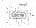
- Fig. 2 is a front view of the power feeding coil 3 of the embodiment.
- the left-right direction in fig. 2 corresponds to the movement direction of the moving body 99.
- Fig. 3 is a cross-sectional view of the power feeding coil 3 when an A-A cross-section shown by the dashed-dotted line in fig. 2 is viewed from the direction of the arrows.
- the power feeding coil 3 is provided with the core 31 and a coil 35.
- the core 31 is an E-type core having a cross-section that is E-shaped, and is composed of a bottom face section 32, a center leg section 33, and two side leg sections 34.
- the bottom face section 32 is formed in a rectangular plate form.
- the two side leg sections 34, on which the coil 35 is not installed, are erected from the two long sides of the bottom face section 32, and are parallel to one another.
- the center leg section 33, on which the coil 35 is installed, is erected from the center of the bottom face section 32.
- the center leg section 33 is parallel to the two side leg sections 34, and the length thereof in the movement direction is less than those of the side leg sections 34.
- the height dimensions to which the center leg section 33 and the side leg sections 34 are erected are mutually equivalent.
- the core 31 can be formed as an integral product by sintering a magnetic powder, or stacking electromagnetic steel sheets.
- the coil 35 is disposed around the center leg section 33.
- the coil 35 is formed by winding a wire 36 around a coil mold whose shape is equivalent to the shape of the center leg section 33.
- the wire 36 has an insulating covering 38 around a conductor 37.
- the conductor 37 is a single conductor composed of a single wire having a circular cross-section with a diameter Dc, and is configured from a copper wire, an aluminum wire, or the like.
- the invention is not limited to this configuration, and the conductor 37 may be rectangular with a chamfered cross-section, or the like, may be a composite conductor composed of a plurality of wires, or may be a material other than copper or aluminum.
- the insulating covering 38 is configured from a resin, or the like, and the covering thickness on one side thereof is Ti.
- the wire 36 is wound around, in a parallel manner, an opposing intermediate face Sn when a power feeding coil 3 and a power receiving coil 4 oppose one another.
- the coil 35 is configured by 12 turns in total, including 6 turns in each of two layers. The number of layers of the coil 35 and the number of turns per layer can be altered as appropriate. As shown by fig. 2 , both ends 351 and 352 of the coil 35 are lead out in the short side direction of the bottom face section 32 of the core 31.
- the cross-sectional area of the conductor 37 or in other words, the diameter Dc of the circular cross-section is set on the basis of a coil resistance value R.
- the coil resistance value R is calculated by adding a DC resistance value Rdc of the coil 35, to an AC resistance value Rac of the coil 35, which is a resistance increment caused by a skin effect that occurs at the specific frequency.
- Fig. 4 is a view that shows a result obtained by calculating the relationship between the diameter Dc of the conductor 37 and the resistance values R, Rdc, and Rac of the coil 35 by using a simulation with the power feeding coil 3 as a subject.
- the respective resistance values R, Rdc, and Rac are calculated at six diameters Dc while the covering thickness Ti of the insulating covering 38 is kept constant.
- the coil resistance value R is shown by using a solid line, the DC resistance value Rdc by using a dashed-dotted line, and the AC resistance value Rac by using a broken line.
- the DC resistance value Rdc decreases as the diameter Dc increases in an inversely proportionate manner to the square of the diameter Dc. Meanwhile, since the influence of a skin effect becomes more significant as the diameter Dc increases, the AC resistance value Rac shows an increasing trend. Further, the coil resistance value R, which is obtained by adding the DC resistance value Rdc and the AC resistance value Rac, corresponds to the smallest possible value R1 at a diameter Dc1. In other words, there is an adverse effect on the loss of the power feeding coil 3 regardless of whether the diameter Dc of the conductor 37 is decrease or increased from the diameter Dc1. Therefore, the diameter Dc of the conductor 37 is set on the basis of the diameter Dc1.
- the workability during winding work, the mechanical strength when a fault current flows, and the like, can be considered as other factors for setting the material, cross-sectional shape, and cross-sectional area (diameter Dc in a case of a circular cross-section) of the conductor 37.
- the size of the DC resistance value Rdc is not dependent on the specific frequency, but the size of the AC resistance value Rac is dependent on the specific frequency. Therefore, when the specific frequency is altered, the diameter Dc1 may change.
- Fig. 5 is a view that shows a result obtained by calculating the relationship between the covering thickness Ti of the insulating covering 38 and the resistance values R, Rdc, and Rac of the coil 35 by using a simulation with the power feeding coil 3 as a subject.
- the respective resistance values R, Rdc, and Rac are calculated at five covering thicknesses Ti while the diameter Dc of the conductor 37 is kept constant.
- the DC resistance value Rdc is shown by using a solid line, the DC resistance value Rdc by using a dashed-dotted line, and the AC resistance value Rac by using a broken line.
- the DC resistance value Rdc increases with an extremely shallow slope as the covering thickness Ti increases. Meanwhile, since the influence of a proximity effect is reduced as the covering thickness Ti increases, the AC resistance value Rac shows a decreasing trend. In this instance, the condition of the influence of a proximity effect corresponding to a predetermined amount or less can be replaced with a condition of the AC resistance value Rac corresponding to a predetermined resistance value R2 or less.
- the covering thickness Ti of the insulating covering 38 corresponds to a covering thickness Ti2 or less, at which the AC resistance value Rac corresponds to the resistance value R2.
- the covering thickness Ti it is necessary for the covering thickness Ti to be set to a covering thickness Ti3 at which it is possible to ensure insulating performance between portions of the conductor 37. Accordingly, the covering thickness Ti of the insulating covering 38 is set to be the higher of the covering thickness Ti2 and the covering thickness Ti3.
- the core 31 and the coil 35 are formed separately, and are subsequently joined in an integral manner.
- the center leg section 33 of the core 31 is fitted into a hollow section at the center of the coil 35.
- the side leg sections 34 of the core 31 cover, among an outer peripheral section of the coil 35, a partial range that is parallel to the movement direction of the moving body 99.
- the core 31 is not covered in, among the outer peripheral section of the coil 35, the remaining range that intersects the movement direction.
- the bottom face section 32 of the core 31 covers an end face section on a side that is separated from the opposing intermediate face Sn of the coil 35.
- a plurality of the power feeding coils 3 are used aligned in the movement direction of the moving body 99. Therefore, between power feeding coils 3, the majority of magnetic flux leakage is directed toward a neighboring power feeding coil 3, and an extremely small part of leakage flux leaks to the outside. In other words, among the outer peripheral section of the coil 35, the necessity for magnetic shielding in the remaining range is low. Accordingly, even if the side leg sections are not provided to the two short sides of the bottom face section 32, a sufficient magnetic shielding effect is obtained. As a result of this, the shape of the core 31 is simplified, and effects of reductions in weight and cost are achieved.
- Fig. 6 is a front view of the power receiving coil 4 of the embodiment.
- the left-right direction in fig. 6 corresponds to the movement direction of the moving body 99.
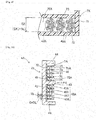
- Fig. 7 is a cross-sectional view of the power receiving coil 4 when a B-B cross-section shown by the dashed-dotted line in fig. 6 is viewed from the direction of the arrows .
- the power receiving coil 4 is provided with a core 41, a coil 45 and a bobbin 7.
- the core 41 is an E-type core having a cross-section that is E-shaped, and is composed of a bottom face section 42, a center leg section 43, and two side leg sections 44.
- the bottom face section 42 is formed in a rectangular plate form.
- the two side leg sections 44, on which the coil 45 is not installed, are erected from the two long sides of the bottom face section 42, and are parallel to one another.
- the center leg section 43, on which the coil 45 is installed, is erected from the center of the bottom face section 42.
- the center leg section 43 is parallel to the two side leg sections 44, and the length thereof in the movement direction is less than those of the side leg sections 44.
- the direction in which the center leg section 43 is erected corresponds to an axis line AX-direction that is perpendicular to the opposing intermediate face Sn.
- the height dimensions to which the center leg section 43 and the side leg sections 44 are erected are mutually equivalent.
- the core 41 can be formed as an integral product by sintering a magnetic powder, or stacking electromagnetic steel sheets.
- a length dimension LR of the core 41 of the power receiving coil 4 is shorter than a length dimension LS (refer to fig. 2 ) of the core 31 of the power feeding coil 3.
- a width dimension WR of the core 41 of the power receiving coil 4 is substantially equivalent to a width dimension WS (refer to fig. 2 ) of the core 31 of the power feeding coil 3.
- the bobbin 7 is composed of a center leg main partition section 71, a bottom face main partition section 72, an inter-inter-block partition section 73, and a block end partition section 74.
- the center leg main partition section 71 is a rectangular tubular shape that orbits the center leg section 43 of the core 41.
- the bottom face main partition section 72, the inter-block partition section 73, and the block end partition section 74 are respectively annular plate-like sites, and are disposed in a mutually parallel manner in contact with the periphery of the center leg main partition section 71.
- the bottom face main partition section 72 is disposed in contact with the bottom face section 42 of the core 41.
- the block end partition section 74 is disposed to match the end surfaces of the center leg section 43 and the side leg sections 44 of the core 41.
- the inter-block partition section 73 is disposed in the middle of the bottom face main partition section 72 and the block end partition section 74.
- the coil accommodation spaces 75 correspond to annular empty spaces that are shallow in the axis line AX-direction.
- the bobbin 7 has a solid coil mold function around which the coil 45 is wound and formed, and has a function of ensuring insulating performance between the core 41 and the coil 45.
- the bobbin 7 can be formed as an integral product by using a method such as joining of multiple resin members, cast resin molding, or the like.
- the coil 45 is composed of two annular plate-shaped coil blocks 453 and 454.
- the two annular plate-shaped coil blocks 453 and 454 are accommodated in the respective coil accommodation spaces 75, and are aligned separated from one another in the axial line direction AX.
- the annular plate-shaped coil blocks 453 and 454 are formed by winding a litz wire 49 around the axis line AX direction six turns in the radial direction. Additionally, the number of winding turns of the litz wire 49 is not limited to six turns.
- a wire having an insulating covering around a single conductor may be used.
- the two annular plate-shaped coil blocks 453 and 454 are electrically connected in series, but may be connected in parallel.
- Fig. 8 is a partial cross-sectional view that schematically shows the litz wire 49 and a coil accommodation space 75 that are used in the power receiving coil 4.
- the litz wire 49 is configured be seven wires 46 being twisted together, but may also have another configuration. As shown by the broken line, the cross-sectional shape of the litz wire 49 is equivalent to being circular, and an equivalent outer diameter dimension thereof is DL.
- the wire 46 has an insulating covering 48 around a conductor 47.
- the conductor 47 is configured to be a copper wire or an aluminum wire have a circular cross-section.
- the insulating covering 48 is configured to be a formal resin.
- the litz wire 49 can significantly decrease the influence of a skin effect in comparison with a single wire having a large diameter, and has an effect of decreasing AC loss of the power receiving coil 4.
- the litz wire 49 is wound around, in a parallel manner, the opposing intermediate face Sn when a power feeding coil 3 and a power receiving coil 4 oppose one another. As shown by fig. 6 , both ends 451 and 452 of the coil 45 are lead out in the short side direction of the bottom face section 42 of the core 41.
- the gap dimension G of the two coil accommodation spaces 75 is set so as to be equivalent to the equivalent outer diameter dimension DL of the litz wire 49. Therefore, in winding work for forming the power receiving coil 4, shape loss of the cross-sectional shape of the litz wire 49 does not occur. Accordingly, in the power receiving coil 4, in comparison with the use of a single wire having a large diameter, a decreasing effect on AC loss is significant when the litz wire 49 is used.
- Fig. 9 is a partial cross-sectional view that describes a case in which shape loss occurs in the litz wire 49X as an illustrative example.
- shape loss occurs in the circular cross-sectional shape of a litz wire 49X due to forces applied during coil work. As a result of this, there is a concern that the decreasing effect on AC loss will be lost when the litz wire 49X is used.
- the covering thickness Tb of the inter-block partition section 73 is set so that the influence of a proximity effect that occurs at the specific frequency between portions of the litz wire 49 with the inter-block partition section 73 interposed therebetween corresponds to a predetermined amount or less.
- the influence of a proximity effect is decreased by increasing the thickness Tb.
- increasing the thickness Tb is directly linked with increases in the size, weight, cost, and the like, of the power receiving coil 4. Accordingly, these disadvantages are also taken into consideration in a comprehensive manner, and the thickness Tb of the inter-block partition section 73 is set as an optimum value. As a result of this, in the power receiving coil 4, the occurrence of AC loss caused by a proximity effect is appropriately suppressed.
- the coil 45 is formed by winding the litz wire 49 around the bobbin 7 serving as a coil mold. Thereafter, the coil 45 and the bobbin 7 are joined to the core 41, which is formed separately, in an integral manner. As a result of joining in an integral manner, the center leg section 43 of the core 41 is fitted into a hollow section at the center of the coil 45 and the center leg main partition section 71 of the bobbin 7.
- the side leg sections 44 of the core 41 cover, among an outer peripheral section of the coil 45, a partial range that is parallel to the movement direction of the moving body 99.
- the core 41 is not covered in, among the outer peripheral section of the coil 45, the remaining range that intersects the movement direction of the moving body 99.
- the bottom face section 42 of the core 41 covers an end face section on a side that is separated from the opposing intermediate face Sn of the coil 45.
- the coil 45 using three or more annular plate-shaped coil blocks.
- the numbers of the inter-block partition sections 73 and the coil accommodation spaces 75 are increased to correspond to the number of annular plate-shaped coil blocks.
- Fig. 10 is a cross-sectional view of the power receiving coil 4A of another embodiment.
- the power receiving coil 4A is provided with a core 41, a coil 45A, and a bobbin 7A.
- the core 41 shown in fig. 10 has the same shape as the cores 41 shown in figs. 6 and 7 .
- the bobbin 7A is an integral product composed of a center leg main partition section 71, a bottom face main partition section 72, and four inter-block partition sections 76 to 79.
- the center leg main partition section 71 is a rectangular tubular shape that orbits the center leg section 43 of the core 41.
- the bottom face main partition section 72 is an annular plate-like site, is disposed at the periphery of the center leg main partition section 71, and is in contact with the bottom face section 42 of the core 41.
- the four inter-block partition sections 76 to 79 are rectangular tubular shape sites.
- the four inter-block partition sections 76 to 79 are disposed in the periphery of the center leg main partition section 71 separated from one another on the inside and the outside. One end in the axis line AX-direction of each of the inter-block partition sections 76 to 79 is linked to the bottom face main partition section 72.
- a coil accommodation space 75A is defined between the center leg main partition section 71 and the inter-block partition section 76 furthest on the inside. Furthermore, coil accommodation spaces 75A are respectively defined between the inter-block partition sections 76 to 79. In total, four coil accommodation spaces 75A correspond to tubular empty spaces.
- the gap dimension G in a direction that intersects the axis line AX of the coil accommodation spaces 75A is set to be equivalent to the equivalent outer diameter dimension DL of the litz wire 49.
- the coil 45A is composed of four tubular coil blocks 455 to 458, which are aligned in the radial direction.
- Each tubular coil block 455 to 458 is respectively accommodated in a coil accommodation space 75A.
- the tubular coil blocks 455 to 458 are formed by winding a litz wire 49 around the axis line AX-direction two turns in the axis line AX direction.
- the number of winding turns of the litz wire 49 is not limited to two turns.
- the four tubular coil blocks 455 to 458 are electrically connected in series, but may be connected in parallel.
- the gap dimension G of each coil accommodation space 75A is equivalent to the equivalent outer diameter dimension DL of the litz wire 49, shape loss does not occur in the litz wire 49 in coil work. Accordingly, in the power receiving coil 4A, in comparison with the use of a single wire having a large diameter, an effect of decreasing AC loss is significant when the litz wire 49 is used.
- the covering thickness Tb of the inter-block partition sections 76 to 78 is set so that the influence of a proximity effect that occurs at the specific frequency between portions of the litz wire 49 with the inter-block partition sections 76 to 78 interposed therebetween corresponds to a predetermined amount or less. As a result of this, in the power receiving coil 4A, the occurrence of AC loss caused by a proximity effect is also appropriately suppressed.
- the power feeding coil 3 is equivalent to an embodiment of a non-contact power feeding coil of the present invention.
- the power feeding coil 3 is a non-contact power feeding coil that configures the non-contact power feeding system 1 and is provided with the coil 35 through which an AC current of the specific frequency flows, and the core 31 that forms a section of a circulating magnetic path, which is interlinked with the coil 35, in the coil 35, the wire 36 having the insulating covering 38 is wound around the conductor 37, and the covering thickness Ti of the insulating covering 38 is set so that the influence of a proximity effect that occurs at the specific frequency between adjacent portions of the wire 36 is a predetermined amount or less.
- the covering thickness Ti of the insulating covering 38 of the wire 36 is set so as to ensure the insulating performance between portions of the conductor 37, and also so that the influence of a proximity effect is a predetermined amount or less. Therefore, it is possible to freely adjust a separation distance between portions of the conductor 37 by altering the covering thickness Ti; and therefore, the occurrence of AC loss caused by a proximity effect is appropriately suppressed.
- portions of the wire 36 having the insulating covering 38 may be brought into contact with one another. Accordingly, dedicated designs are not required in the coil work for forming the coil 35, and there is no difficulty in the dimensional accuracy and work man-hours.
- the cross-sectional area of the conductor 37 of the power feeding coil 3, or in other words, the diameter Dc of the circular cross-section of the conductor 37 is set on the basis of the coil resistance value R obtained by adding the DC resistance value Rdc of the coil 35, and the AC resistance value Rac of the coil 35, which is a resistance increment caused by a skin effect that occurs at the specific frequency.
- an optimum cross-sectional area, or in other words, an optimum diameter Dc is set, and the occurrence of AC loss caused by a skin effect is suppressed.
- there is a saving in the amount of use of the wire 36 reductions in the weight and cost of the power feeding coil 3 are possible.
- the conductor 37 of the power feeding coil 3 may be a composite conductor composed of a plurality of wires or a single conductor composed of a single wire. According to this configuration, since it is possible to select the type of the conductor 37 to match the power feeding capacity, difficulty of winding work, and the like, required in the power feeding coil 3, there is a large degree of design freedom.
- the wire 36 is wound around, in a parallel manner, the opposing intermediate face Sn when a power feeding coil 3 and a power receiving coil 4 oppose one another, and the core 31 has the center leg section 33 that is fitted into a hollow section at the center of the coil 35, the side leg sections 34 that cover an outer peripheral section of the coil 35, and a bottom face section 32 that covers an end face section on a side that is separated from the opposing intermediate face Sn of the coil 35.
- the core 31 also serves as a magnetic shielding member. Accordingly, in comparison with the related art, reductions in the weight and cost of the power feeding coil 3 are possible.
- the power feeding coils 3 are used in a manner of being aligned in a predetermined direction (the movement direction of the moving body 99), and the side leg sections 34 of the core 31 cover, among the outer peripheral section of the coil 35, a partial range that is parallel to the predetermined direction and do not cover a remaining range that intersects the predetermined direction. According to this configuration, since a sufficient magnetic shielding effect can be obtained even if the side leg sections, which cover the remaining range, are not provided, the shape of the core 31 is simplified, and therefore, reductions in the weight and cost thereof are possible.
- a non-contact power feeding system 1 of the embodiment is a the non-contact power feeding system 1 provided with a power feeding coil provided in the power feeding unit 1S, the AC power supply circuit 2 that supplies AC power of the specific frequency to the power feeding coil, a power receiving coil 4 that is provided in the power receiving unit 1R, the power receiving coil electrically coupling with and receiving AC power in a non-contact manner when opposing the power feeding coil, and a power receiving circuit 5 that converts AC power received by the power receiving coil 4, generates a drive voltage, and outputs the drive voltage to the electrical load
- the power feeding coil is the above-mentioned power feeding coil 3
- the power receiving coils 4 or 4A include the coil 45 or 45A through which an AC current of the specific frequency flows and the core 41 that forms a section of a circulating magnetic path, which is interlinked with the coil 45 or 45A
- the coil 45 or 45A is composed of multiple coil blocks (annular plate-shaped coil blocks 453 and 454, or tubular coil blocks 455 to 458) in which
- the power receiving coil 4 or 4A is provided with the coil 45 or 45A that is composed of the multiple coil blocks in which the litz wire 49 is respectively wound, and the bobbin 7 or 7A having the inter-block partition sections 73 or 76 to 78 that partition the multiple coil blocks. Therefore, the separation distance between portions of the litz wire 49 on both sides with the intersect-block partition sections 73 or 76 to 78 interposed therebetween are increased by the thickness Tb of the intersect-block partition sections 73 or 76 to 78, and the occurrence of AC loss caused by a proximity effect is suppressed. Accordingly, AC loss is decreased in both the power feeding coil 3 and the power receiving coil 4 or 4A, and favorable power feeding efficiency can be obtained in the non-contact power feeding system 1.
- an identical number of the power feeding units 1S are provided in the multiple first to third board production machines 91 to 93 that configure a board production line 9, and the power receiving unit 1R is provided in the moving body 99 that moves in the linear arrangement direction of the multiple first to third board production machines 91 to 93.
- non-contact power feeding system 1 it is possible to dispose two power feeding-side coils 3 lined up in the movement direction of the front face in a board production machine having a large width dimension ML.
- Various other applications and modifications are also possible in the present invention.
- the non-contact power feeding coil of the present invention can be applied to system configurations other than that of the non-contact power feeding system 1 of the embodiment.
- the non-contact power feeding system 1 of the embodiment is not limited to application to the board production line 9, and can be applied to a broad range of fields such as assembly lines and processing lines that produce other products, and power supply during travel of an electrically driven vehicle.
Landscapes
- Engineering & Computer Science (AREA)
- Power Engineering (AREA)
- Transportation (AREA)
- Mechanical Engineering (AREA)
- Computer Networks & Wireless Communication (AREA)
- Physics & Mathematics (AREA)
- Electromagnetism (AREA)
- Manufacturing & Machinery (AREA)
- Microelectronics & Electronic Packaging (AREA)
- Current-Collector Devices For Electrically Propelled Vehicles (AREA)
- Coils Of Transformers For General Uses (AREA)
- Insulating Of Coils (AREA)
Abstract
Description
- The present invention relates to a non-contact power feeding coil provided with a coil and a core, and to a non-contact power feeding system configured using the non-contact power feeding system.
- A solder printing machine, an electronic component mounting machine, a reflow machine, a board inspection machine, and the like, are examples of board production machines that produce boards on which multiple components are mounted. Generally, a board production line is configured by linking such equipment. Furthermore, there are many cases in which a board production line is configured by linearly arranging modularized board production machines of the same size. As a result of the use of modularized board production machines, setup changing work during rearrangement of a line and during expansion for increasing the size of a line is facilitated, and a flexible board production line is realized.
- In recent years, the promotion of labor-saving efforts and automation by conveying the equipment, members, and the like, used in each board production machine of a board production line to a moving body, which moves along the board production line, has been examined. Furthermore, non-contact power feeding systems have been considered as power supply means to a moving body. Additionally, applications of non-contact power feeding systems are not limited to board production lines, and are present throughout a broad range of fields such as assembly lines and processing lines that produce other products, and power supply during travel of an electrically driven vehicle. In such a non-contact power feeding system, an electromagnetic coupling technique that respectively uses coils in a power feeding element and a power receiving element is widely used. A technical example relating to an electromagnetic coupling technique non-contact power feeding system is disclosed in PTL 1. Additionally, in the present description, the electromagnetic coupling technique includes an electromagnetic induction technique and an electromagnetic field resonance technique.
- The non-contact power transmission device of PTL 1 is provided with coils in a power delivery section (power feeding unit) and a power receiving section (power receiving unit) respectively, performs power delivery and power reception via each coil, converts received AC power into DC power and supplies the DC power to a load. In addition to PTL 1, other electromagnetic coupling technique non-contact power feeding systems are generally configured such that power feeding can be performed across a space by using a significantly higher frequency than a commercial frequency. However, as a result of the frequency being high, loss increases due to AC loss and leakage flux of a coil, and therefore, there is a tendency for power feeding efficiency to decrease.
- The AC loss is generated by an eddy current in the coil, and increases as the frequency increases. AC loss includes AC loss caused by a skin effect that is generated in a single conductor and AC loss caused by a proximity effect that is generated between multiple conductors. In addition, since an electric current flows into and heat is generated in peripheral metal objects to which leakage flux reaches, an increase in loss is caused. Various technical examples of non-contact power feeding coils in which an increase in loss is suppressed are disclosed in
PTL 2 to 4. -
PTL 2 discloses a planar coil composed of a coiled wire section that is used in a power delivery coil (power feeding coil) or a coil for power reception (power receiving coil) of a non-contact power transmission machine. The planar coil is characterized by a gap for suppressing eddy currents being provided between wire sections. According to this configuration, adjacent wire sections mutually influence one another, the generation of an eddy current is suppressed (suppression of a proximity effect), and heat generation of the planar coil is reduced. -
PTL 3 discloses a power feeding section provided with a power supply, a power feeding-side resonance coil, and a conductive shielding case in which the coil is accommodated. The power feeding section is further provided with a magnetic body that is disposed outside the shielding case. According to this configuration, among the magnetic field emitted by the power feeding-side resonance coil, since magnetic field leakage leaked from the shielding case is absorbed by the magnetic body (ferrite), it is possible to sufficiently prevent electromagnetic leakage. -
PTL 4 discloses a non-contact power feeding coil provided with a coil main body around which a wire is wound, said core main body having an H-shaped core, a case main body in which the coil main body is accommodated, the case main body being made from a resin, and a non-magnetic conductive plate for magnetic shielding to which the case main body is fixed. The non-contact power feeding coil device for non-contact power feeding is disposed on a rear face of the non-magnetic conductive plate in a housing in which a resonance capacitor and a rectifier circuit are accommodated. Furthermore, the embodiments describe a litz wire as a countermeasure for reducing loss. According to this configuration, it is possible to configure the device in a compact manner by using a short wiring line, and therefore, a reduction in power feeding efficiency is moderated without losing a magnetic shielding effect. -
- PTL 1:
JP-A 2011-205783 - PTL 2:
JP-A 2009-158598 - PTL 3:
JP-A 2014-176133 - PTL 4:
JP-A 2012-204469 - It should be noted that in the manufacturing method of the planar coil described in the embodiments of
PTL 2, the wire sections are laid on a sheet using a dedicated wire-laying device in order to ensure a gap between wire sections. In addition to this, a method that performs winding work for forming a coil while inserting a spacer between wire sections can also be considered. However, even if such ideas are adopted, manufacture of a planar coil is not easy, and an increase in AC loss due to a reduction in dimensional accuracy and an increase in work man-hours required for manufacturing are considered to be difficulties. - In addition, in the technical example of
PTL 3, even if it is possible to prevent electromagnetic leakage to outside the magnetic body, leakage flux enters the shielding case on the inner side of the magnetic body. Accordingly, eddy current loss is generated in the shielding case and there is an increase in loss. In addition, the litz wire disclosed inPTL 4 is expensive compared to a wire composed of a single conductor, but it is possible to significantly reduce AC loss caused by a skin effect. However, there is a concern that shape loss will occur in the cross-sectional shape of the litz wire during winding work, and that the effect of reducing AC loss will be lost. - In the above-mentioned manner, when loss of a power feeding coil and a power receiving coil is increased, naturally, the power feeding efficiency of the non-contact power feeding system decreases.
- The present invention has been devised in the light of the above-mentioned problems of the background art, and addresses a problem of providing a non-contact power feeding coil in which the occurrence of AC loss is suppressed, and providing a non-contact power feeding system in which favorable power feeding efficiency can be obtained by using the non-contact power feeding coil.
- The present invention that solves the above-mentioned problems is to provide a non-contact power feeding coil. The non-contact power feeding coil that is used in at least one of a power feeding coil and a power receiving coil that configure a non-contact power feeding system is provided with a coil through which an AC current of a specific frequency flows, and a core that forms a section of a circulating magnetic path, which is interlinked with the coil, in the coil, a wire having an insulating covering is wound around a conductor, and a covering thickness of the insulating covering is set so that the influence of a proximity effect that occurs at the specific frequency between adjacent portions of the wire is a predetermined amount or less.
- In addition, a non-contact power feeding system of the present invention is provided with a power feeding coil provided in a power feeding unit, an AC power supply circuit that supplies AC power of the specific frequency to the power feeding coil, a power receiving coil that is provided in a power receiving unit, the power receiving coil electrically coupling with and receiving AC power in a non-contact manner when opposing the power feeding coil, and a power receiving circuit that converts AC power received by the power receiving coil, generates a drive voltage, and outputs the drive voltage to an electrical load, the power feeding coil is the above-mentioned non-contact power feeding coil of the present invention, and the power receiving coil includes a coil through which an AC current of the specific frequency flows and a core that forms a section of a circulating magnetic path, which is interlinked with the coil, the coil is composed of a plurality of coil blocks in which a wires having insulating coverings around conductors are respectively wound, and further includes a bobbin having a main partition section that partitions the coil and the core, and an inter-block partition section that partitions the plurality of coil blocks.
- In the non-contact power feeding coil of the present invention, the occurrence of AC loss caused by a proximity effect is suppressed.
- In the non-contact power feeding system of the present invention, favorable power feeding efficiency can be obtained.
-
- [
Fig. 1] Fig. 1 is a view that schematically describes an entire configuration of a non-contact power feeding system of an embodiment. - [
Fig. 2] Fig. 2 is a front view of a power feeding coil of the embodiment. - [
Fig. 3] Fig. 3 is a cross-sectional view of the power feeding coil when an A-A cross-section shown by the dashed-dotted line infig. 2 is viewed from the direction of the arrows. - [
Fig. 4] Fig. 4 is a view that shows a result obtained by calculating the relationship between the diameter of a conductor and the resistance values of a coil by using a simulation with the power feeding coil as a subject. - [
Fig. 5] Fig. 5 is a view that shows a result obtained by calculating the relationship between the covering thickness of an insulating covering and the resistance values of the coil by using a simulation with the power feeding coil as a subject. - [
Fig. 6] Fig. 6 is a front view of a power receiving coil of the embodiment. - [
Fig. 7] Fig. 7 is a cross-sectional view of the power receiving coil when a B-B cross-section shown by the dashed-dotted line infig. 6 is viewed from the direction of the arrows. - [
Fig. 8] Fig. 8 is a partial cross-sectional view that schematically shows a litz wire and a coil accommodation space that are used in the power receiving coil. - [
Fig. 9] Fig. 9 is a partial cross-sectional view that describes a case in which shape loss occurs in the litz wire as an illustrative example. - [
Fig. 10] Fig. 10 is a cross-sectional view of a power receiving coil of another embodiment. - A non-contact power feeding system 1 of an embodiment of the present invention will be described below with reference to
fig. 1. Fig. 1 is a view that schematically describes an entire configuration of the non-contact power feeding system 1 of the embodiment. The non-contact power feeding system 1 of the embodiment can be applied to aboard production line 9. As illustrated in the drawings, theboard production line 9 is configured by three first to thirdboard production machines 91 to 93 being linearly arranged. The left-right direction infig. 1 is a linear arrangement direction of the first to thirdboard production machines 91 to 93, and is also a movement direction of a movingbody 99, which will be mentioned later. - Each
board production machine 91 to 93 is modularized, and width dimensions ML in the linear arrangement direction thereof are equivalent. The first to thirdboard production machines 91 to 93 are configured so that alterations in the order of the linear arrangement positions and replacements with other modularized board production machines can be made. The number of linearly arranged board production machines that configure theboard production line 9 may be four or more, and theboard production line 9 is also compatible with module expansion for increasing the number of linearly arranged machines. In other words, during alteration or of the order of or increase of the board production machines, a movingbody 99 can move along the linearly arranged board production machines without performing wiring of cables, or the like, for performing power feeding in a non-contact manner. Electronic component mounting machines can be included as illustrative examples of the first to thirdboard production machines 91 to 93, but the invention is not limited to this configuration. - A guide rail, which extends in the linear arrangement direction but is not illustrated in the drawings, is installed in front of the first to third
board production machines 91 to 93. The movingbody 99 moves in the movement direction (the linear arrangement direction of the first to thirdboard production machines 91 to 93) along the guide rail. The movingbody 99 has roles of carrying in equipment, members, and the like, that are used by eachboard production machine 91 to 93 from a storage container, which is not illustrated in the drawings, and returning equipment, members, and the like, to the storage container after use. - The non-contact power feeding system 1 of the embodiment is a system that performs non-contact power feeding from the first to third
board production machines 91 to 93 with the movingbody 99 as a power feeding target by using an electromagnetic coupling technique. The non-contact power feeding system 1 is configured frompower feeding units 1S respectively provided on the front side of eachboard production machine 91 to 93, and twopower receiving units 1R provided in the movingbody 99. - The
power feeding units 1S are configured by an ACpower supply circuit 2, apower feeding coil 3, and the like. The ACpower supply circuit 2 supplies AC power of a specific frequency to thepower feeding coil 3. For example, the ACpower supply circuit 2 can be configured using a DC power supply section that supplies a DC voltage, and a publicly-known bridge circuit that AC converts the DC voltage. Afirst output terminal 21 of the ACpower supply circuit 2 is directly coupled with one end of thepower feeding coil 3, and asecond output terminal 22 is connected to one end of a power feeding-side capacitor 61. The specific frequency of the ACpower supply circuit 2 is set on the basis of resonance frequencies of a power feeding-side resonance circuit and a power receiving-side resonance circuit, which will be mentioned later. Frequencies of the order of a few tens of kHz to a few hundred kHz can be included as illustrative examples of the specific frequency, but the invention is not limited to this configuration. The ACpower supply circuit 2 includes a function of adjusting voltage value, and the like. - The total of three AC
power supply circuits 2 provided in the threeboard production machines 91 to 93 can be operated independently of one another. Eachboard production machine 91 to 93 has a sensor which detects proximity of the movingbody 99 but is not illustrated in the drawings. Further, the ACpower supply circuit 2 of eachboard production machine 91 to 93 operates only when the movingbody 99 comes into proximity therewith. As a result of this, at times when the movingbody 99 is separated far away, the ACpower supply circuit 2 is stopped, and unnecessary electrical loss does not occur. - The power feeding coils 3 are provided on the front face of each
board production machine 91 to 93, and are formed to have a symmetric shape at the front and back in a conveyance direction. The power feeding-side capacitor 61 is a resonance element that forms the power feeding-side resonance circuit by being connected in series to thepower feeding coil 3. The other end of the power feeding-side capacitor 61 is connected to the other end of thepower feeding coil 3. As a result of this, an annular power feeding circuit is configured. Accordingly, an AC current of the specific frequency flows in thepower feeding coil 3. - Meanwhile, the
power receiving units 1S are configured by apower receiving coil 4, apower receiving circuit 5, and the like. The two power receiving coils 4 are installed, in the movingbody 99, on aside face 98 that opposes the power feeding coils 3, and are disposed spatially separated from one another in the movement direction. When The power feeding coils 3 and the power receiving coils 4 are disposed with an opposing intermediate face Sn interposed therebetween,cores - One end of each
power receiving coil 4 is connected to one end of a power receiving-side capacitor 65 and one terminal on an input side of arectifier circuit 51 that configures thepower receiving circuit 5. The other end of thepower receiving coil 4 is connected to the other end of the power receiving-side capacitor 65 and the other terminal on the input side of therectifier circuit 51. The power receiving-side capacitor 65 is a resonance element that forms a power receiving-side resonance circuit by being connected in parallel to thepower receiving coil 4. - The
power receiving circuit 5 converts the AC power received by thepower receiving coil 4 and generates a drive voltage. Thepower receiving circuit 5 is configured to include therectifier circuits 51, which are provided for eachpower receiving coil 4, and a DCpower supply circuit 55, which is provided commonly to the tworectifier circuits 51. Eachrectifier circuit 51 is configured by a full-wave rectifier, which is bridge connected to four rectifier diodes, and a smoothing capacitor, which is connected to the output side of the full-wave rectifier circuit. The tworectifier circuits 51 convert the AC power received by the power receiving coils 4 into a DC voltage and output the DC voltage. The output side of the tworectifier circuits 51 are connected in parallel to the DCpower supply circuit 55. - The DC
power supply circuit 55 converts the DC voltage into a drive voltage, and outputs the drive voltage to an electrical load EL mounted in the movingbody 99. The DCpower supply circuit 55 has a stabilization action of the drive voltage. In other words, the DCpower supply circuit 55 adjusts DC voltages having an unstable voltage values, which are output from therectifier circuits 51, to a drive voltage having a largely fixed voltage, and outputs the drive voltage to the electrical load EL. A switching system or dropper system DC-DC converter are illustrative examples of the DCpower supply circuit 55. The DCpower supply circuit 55 is provided with a step-down function and may be further provided with a step-up function. - The electrical load EL performs work in the moving
body 99, the type, power consumption, and the like, thereof are not limited. For example, the electrical load EL may include a driving source for movement of the movingbody 99, for example, a stepping motor, a servomotor, or the like. - In this instance, the lengths of the power feeding coils 3 and the power receiving coils 4 in the movement direction, and the mutual adjacent separation distances in the movement direction are set so that non-contact power feeding is performed stably. In other words, a
power feeding coil 3 and at least onepower receiving coil 4 are in a directly facing state at all times regardless of the position of the movingbody 99. A directly facing state refers to a state in which the entire length of apower receiving coil 4 in the movement direction opposes a range of the length of apower feeding coil 3 in the movement direction. - In the positional relationship illustrated by way of example in
fig. 1 , thepower feeding coil 3 of the firstboard production machine 91 and thepower receiving coil 4 on the left side in the drawing directly face one another, and thepower feeding coil 3 of the secondboard production machine 92 and thepower receiving coil 4 on the right side in the drawing directly face one another. At this time, the two power receiving coils 4 are both in favorable power receiving states, and as shown by the arrows P1 and P2, it is possible to receive a large amount of AC power. Apower receiving coil 4 in a directly facing state has a power reception capacity corresponding to an amount capable of driving the electrical load EL individually. Accordingly, a battery and a charging circuit are not required in the non-contact power feeding system 1. - Next, a detailed configuration of the
power feeding coil 3 of the embodiment will be described. Thepower feeding coil 3 is equivalent to an embodiment of a non-contact power feeding coil of the present invention.Fig. 2 is a front view of thepower feeding coil 3 of the embodiment. The left-right direction infig. 2 corresponds to the movement direction of the movingbody 99.Fig. 3 is a cross-sectional view of thepower feeding coil 3 when an A-A cross-section shown by the dashed-dotted line infig. 2 is viewed from the direction of the arrows. Thepower feeding coil 3 is provided with thecore 31 and acoil 35. - As shown by
fig. 3 , thecore 31 is an E-type core having a cross-section that is E-shaped, and is composed of abottom face section 32, acenter leg section 33, and twoside leg sections 34. Thebottom face section 32 is formed in a rectangular plate form. The twoside leg sections 34, on which thecoil 35 is not installed, are erected from the two long sides of thebottom face section 32, and are parallel to one another. Thecenter leg section 33, on which thecoil 35 is installed, is erected from the center of thebottom face section 32. Thecenter leg section 33 is parallel to the twoside leg sections 34, and the length thereof in the movement direction is less than those of theside leg sections 34. The height dimensions to which thecenter leg section 33 and theside leg sections 34 are erected are mutually equivalent. For example, the core 31 can be formed as an integral product by sintering a magnetic powder, or stacking electromagnetic steel sheets. - The
coil 35 is disposed around thecenter leg section 33. Thecoil 35 is formed by winding awire 36 around a coil mold whose shape is equivalent to the shape of thecenter leg section 33. Thewire 36 has an insulatingcovering 38 around aconductor 37. Theconductor 37 is a single conductor composed of a single wire having a circular cross-section with a diameter Dc, and is configured from a copper wire, an aluminum wire, or the like. The invention is not limited to this configuration, and theconductor 37 may be rectangular with a chamfered cross-section, or the like, may be a composite conductor composed of a plurality of wires, or may be a material other than copper or aluminum. The insulatingcovering 38 is configured from a resin, or the like, and the covering thickness on one side thereof is Ti. - In the
coil 35, thewire 36 is wound around, in a parallel manner, an opposing intermediate face Sn when apower feeding coil 3 and apower receiving coil 4 oppose one another. In the present embodiment, thecoil 35 is configured by 12 turns in total, including 6 turns in each of two layers. The number of layers of thecoil 35 and the number of turns per layer can be altered as appropriate. As shown byfig. 2 , both ends 351 and 352 of thecoil 35 are lead out in the short side direction of thebottom face section 32 of thecore 31. - In this instance, the cross-sectional area of the
conductor 37, or in other words, the diameter Dc of the circular cross-section is set on the basis of a coil resistance value R. The coil resistance value R is calculated by adding a DC resistance value Rdc of thecoil 35, to an AC resistance value Rac of thecoil 35, which is a resistance increment caused by a skin effect that occurs at the specific frequency.Fig. 4 is a view that shows a result obtained by calculating the relationship between the diameter Dc of theconductor 37 and the resistance values R, Rdc, and Rac of thecoil 35 by using a simulation with thepower feeding coil 3 as a subject. In the simulation, the respective resistance values R, Rdc, and Rac are calculated at six diameters Dc while the covering thickness Ti of the insulatingcovering 38 is kept constant. Infig. 4 , the coil resistance value R is shown by using a solid line, the DC resistance value Rdc by using a dashed-dotted line, and the AC resistance value Rac by using a broken line. - As illustrated in the drawing, the DC resistance value Rdc decreases as the diameter Dc increases in an inversely proportionate manner to the square of the diameter Dc. Meanwhile, since the influence of a skin effect becomes more significant as the diameter Dc increases, the AC resistance value Rac shows an increasing trend. Further, the coil resistance value R, which is obtained by adding the DC resistance value Rdc and the AC resistance value Rac, corresponds to the smallest possible value R1 at a diameter Dc1. In other words, there is an adverse effect on the loss of the
power feeding coil 3 regardless of whether the diameter Dc of theconductor 37 is decrease or increased from the diameter Dc1. Therefore, the diameter Dc of theconductor 37 is set on the basis of the diameter Dc1. The workability during winding work, the mechanical strength when a fault current flows, and the like, can be considered as other factors for setting the material, cross-sectional shape, and cross-sectional area (diameter Dc in a case of a circular cross-section) of theconductor 37. - Additionally, the size of the DC resistance value Rdc is not dependent on the specific frequency, but the size of the AC resistance value Rac is dependent on the specific frequency. Therefore, when the specific frequency is altered, the diameter Dc1 may change.
- In addition, the covering thickness Ti of the insulating
covering 38 is set so that the influence of a proximity effect that occurs at the specific frequency between adjacent portions of thewire 36 corresponds to a predetermined amount or less.Fig. 5 is a view that shows a result obtained by calculating the relationship between the covering thickness Ti of the insulatingcovering 38 and the resistance values R, Rdc, and Rac of thecoil 35 by using a simulation with thepower feeding coil 3 as a subject. In the simulation, the respective resistance values R, Rdc, and Rac are calculated at five covering thicknesses Ti while the diameter Dc of theconductor 37 is kept constant. Infig. 5 , the DC resistance value Rdc is shown by using a solid line, the DC resistance value Rdc by using a dashed-dotted line, and the AC resistance value Rac by using a broken line. - As illustrated in the drawing, the DC resistance value Rdc increases with an extremely shallow slope as the covering thickness Ti increases. Meanwhile, since the influence of a proximity effect is reduced as the covering thickness Ti increases, the AC resistance value Rac shows a decreasing trend. In this instance, the condition of the influence of a proximity effect corresponding to a predetermined amount or less can be replaced with a condition of the AC resistance value Rac corresponding to a predetermined resistance value R2 or less. According to this configuration, the covering thickness Ti of the insulating
covering 38 corresponds to a covering thickness Ti2 or less, at which the AC resistance value Rac corresponds to the resistance value R2. In addition, generally, it is necessary for the covering thickness Ti to be set to a covering thickness Ti3 at which it is possible to ensure insulating performance between portions of theconductor 37. Accordingly, the covering thickness Ti of the insulatingcovering 38 is set to be the higher of the covering thickness Ti2 and the covering thickness Ti3. - By combining and implementing the two simulations described using
Figs. 4 and5 , it is possible to optimize the diameter Dc of theconductor 37 of thewire 36 and the covering thickness Ti of the insulatingcovering 38. As a result of this, in thepower feeding coil 3, the occurrence of AC loss caused by a skin effect and a proximity effect is suppressed. - In a manufacturing step of the
power feeding coil 3, thecore 31 and thecoil 35 are formed separately, and are subsequently joined in an integral manner. As a result of joining in an integral manner, thecenter leg section 33 of thecore 31 is fitted into a hollow section at the center of thecoil 35. Theside leg sections 34 of the core 31 cover, among an outer peripheral section of thecoil 35, a partial range that is parallel to the movement direction of the movingbody 99. Thecore 31 is not covered in, among the outer peripheral section of thecoil 35, the remaining range that intersects the movement direction. Thebottom face section 32 of the core 31 covers an end face section on a side that is separated from the opposing intermediate face Sn of thecoil 35. As a result of this, a magnetic shielding effect that suppresses leakage to the outside of a magnetic flux emitted from thepower feeding coil 3 occurs . Accordingly, in thepower feeding coil 3, loss due to leakage flux is reduced. - In addition, as shown in
fig. 1 , a plurality of the power feeding coils 3 are used aligned in the movement direction of the movingbody 99. Therefore, between power feeding coils 3, the majority of magnetic flux leakage is directed toward a neighboringpower feeding coil 3, and an extremely small part of leakage flux leaks to the outside. In other words, among the outer peripheral section of thecoil 35, the necessity for magnetic shielding in the remaining range is low. Accordingly, even if the side leg sections are not provided to the two short sides of thebottom face section 32, a sufficient magnetic shielding effect is obtained. As a result of this, the shape of thecore 31 is simplified, and effects of reductions in weight and cost are achieved. Additionally, when the side leg sections are provided to the two short sides of thebottom face section 32, there is an adverse effect of no longer being able to from a favorable circulating magnetic path when apower receiving coil 4 is initially shifted from a directly facing positional relationship relative to apower feeding coil 3. - Next, a detailed configuration of the
power receiving coil 4 of the embodiment will be described.Fig. 6 is a front view of thepower receiving coil 4 of the embodiment. The left-right direction infig. 6 corresponds to the movement direction of the movingbody 99.Fig. 7 is a cross-sectional view of thepower receiving coil 4 when a B-B cross-section shown by the dashed-dotted line infig. 6 is viewed from the direction of the arrows . Thepower receiving coil 4 is provided with acore 41, acoil 45 and abobbin 7. - As shown by
fig. 7 , thecore 41 is an E-type core having a cross-section that is E-shaped, and is composed of abottom face section 42, acenter leg section 43, and twoside leg sections 44. Thebottom face section 42 is formed in a rectangular plate form. The twoside leg sections 44, on which thecoil 45 is not installed, are erected from the two long sides of thebottom face section 42, and are parallel to one another. Thecenter leg section 43, on which thecoil 45 is installed, is erected from the center of thebottom face section 42. Thecenter leg section 43 is parallel to the twoside leg sections 44, and the length thereof in the movement direction is less than those of theside leg sections 44. The direction in which thecenter leg section 43 is erected corresponds to an axis line AX-direction that is perpendicular to the opposing intermediate face Sn. The height dimensions to which thecenter leg section 43 and theside leg sections 44 are erected are mutually equivalent. For example, the core 41 can be formed as an integral product by sintering a magnetic powder, or stacking electromagnetic steel sheets. - Relating to the movement direction of the moving
body 99, a length dimension LR of thecore 41 of thepower receiving coil 4 is shorter than a length dimension LS (refer tofig. 2 ) of thecore 31 of thepower feeding coil 3. Meanwhile, a width dimension WR of thecore 41 of thepower receiving coil 4 is substantially equivalent to a width dimension WS (refer tofig. 2 ) of thecore 31 of thepower feeding coil 3. Accordingly, when apower feeding coil 3 directly faces apower receiving coil 4, thecenter leg sections side leg sections body 99 has moved a given amount. - As shown in
fig. 7 , thebobbin 7 is composed of a center legmain partition section 71, a bottom facemain partition section 72, an inter-inter-block partition section 73, and a blockend partition section 74. The center legmain partition section 71 is a rectangular tubular shape that orbits thecenter leg section 43 of thecore 41. The bottom facemain partition section 72, theinter-block partition section 73, and the blockend partition section 74 are respectively annular plate-like sites, and are disposed in a mutually parallel manner in contact with the periphery of the center legmain partition section 71. The bottom facemain partition section 72 is disposed in contact with thebottom face section 42 of thecore 41. The blockend partition section 74 is disposed to match the end surfaces of thecenter leg section 43 and theside leg sections 44 of thecore 41. Theinter-block partition section 73 is disposed in the middle of the bottom facemain partition section 72 and the blockend partition section 74. -
Coil accommodation spaces 75 in which a gap dimension in the axis line AX-direction is G, are respectively defined between the bottom facemain partition section 72 and theinter-block partition section 73, and between theinter-block partition section 73 and the blockend partition section 74. Thecoil accommodation spaces 75 correspond to annular empty spaces that are shallow in the axis line AX-direction. Thebobbin 7 has a solid coil mold function around which thecoil 45 is wound and formed, and has a function of ensuring insulating performance between the core 41 and thecoil 45. For example, thebobbin 7 can be formed as an integral product by using a method such as joining of multiple resin members, cast resin molding, or the like. - As shown in
fig. 7 , thecoil 45 is composed of two annular plate-shaped coil blocks 453 and 454. The two annular plate-shaped coil blocks 453 and 454 are accommodated in the respectivecoil accommodation spaces 75, and are aligned separated from one another in the axial line direction AX. The annular plate-shaped coil blocks 453 and 454 are formed by winding alitz wire 49 around the axis line AX direction six turns in the radial direction. Additionally, the number of winding turns of thelitz wire 49 is not limited to six turns. In addition, in place of thelitz wire 49, a wire having an insulating covering around a single conductor may be used. In the present embodiment, the two annular plate-shaped coil blocks 453 and 454 are electrically connected in series, but may be connected in parallel. -
Fig. 8 is a partial cross-sectional view that schematically shows thelitz wire 49 and acoil accommodation space 75 that are used in thepower receiving coil 4. Thelitz wire 49 is configured be sevenwires 46 being twisted together, but may also have another configuration. As shown by the broken line, the cross-sectional shape of thelitz wire 49 is equivalent to being circular, and an equivalent outer diameter dimension thereof is DL. Thewire 46 has an insulatingcovering 48 around aconductor 47. Theconductor 47 is configured to be a copper wire or an aluminum wire have a circular cross-section. For example, the insulatingcovering 48 is configured to be a formal resin. Thelitz wire 49 can significantly decrease the influence of a skin effect in comparison with a single wire having a large diameter, and has an effect of decreasing AC loss of thepower receiving coil 4. - In the
coil 45, thelitz wire 49 is wound around, in a parallel manner, the opposing intermediate face Sn when apower feeding coil 3 and apower receiving coil 4 oppose one another. As shown byfig. 6 , both ends 451 and 452 of thecoil 45 are lead out in the short side direction of thebottom face section 42 of thecore 41. - In this instance, the gap dimension G of the two
coil accommodation spaces 75 is set so as to be equivalent to the equivalent outer diameter dimension DL of thelitz wire 49. Therefore, in winding work for forming thepower receiving coil 4, shape loss of the cross-sectional shape of thelitz wire 49 does not occur. Accordingly, in thepower receiving coil 4, in comparison with the use of a single wire having a large diameter, a decreasing effect on AC loss is significant when thelitz wire 49 is used. - The state shown in
fig. 9 occurs in a case in which the gap dimension G of thecoil accommodation spaces 75 is set to be larger than the equivalent outer diameter dimension DL of thelitz wire 49.Fig. 9 is a partial cross-sectional view that describes a case in which shape loss occurs in thelitz wire 49X as an illustrative example. In a case in which a gap dimension GX ofcoil accommodation spaces 75X of abobbin 7X is larger than the equivalent outer diameter dimension DL, shape loss occurs in the circular cross-sectional shape of alitz wire 49X due to forces applied during coil work. As a result of this, there is a concern that the decreasing effect on AC loss will be lost when thelitz wire 49X is used. - In addition, even if the gap dimension G of the
coil accommodation spaces 75 is made to be smaller than the equivalent outer diameter dimension DL of thelitz wire 49, shape loss occurs in the circular cross-sectional shape of thelitz wire 49. Moreover, since thelitz wire 49 is forcibly inserted into the narrowcoil accommodation spaces 75, there is a concern that the insulatingcovering 48 will be damaged. - In addition, the covering thickness Tb of the
inter-block partition section 73 is set so that the influence of a proximity effect that occurs at the specific frequency between portions of thelitz wire 49 with theinter-block partition section 73 interposed therebetween corresponds to a predetermined amount or less. The influence of a proximity effect is decreased by increasing the thickness Tb. However, increasing the thickness Tb is directly linked with increases in the size, weight, cost, and the like, of thepower receiving coil 4. Accordingly, these disadvantages are also taken into consideration in a comprehensive manner, and the thickness Tb of theinter-block partition section 73 is set as an optimum value. As a result of this, in thepower receiving coil 4, the occurrence of AC loss caused by a proximity effect is appropriately suppressed. - In a manufacturing step of the
power receiving coil 4, thecoil 45 is formed by winding thelitz wire 49 around thebobbin 7 serving as a coil mold. Thereafter, thecoil 45 and thebobbin 7 are joined to thecore 41, which is formed separately, in an integral manner. As a result of joining in an integral manner, thecenter leg section 43 of thecore 41 is fitted into a hollow section at the center of thecoil 45 and the center legmain partition section 71 of thebobbin 7. Theside leg sections 44 of the core 41 cover, among an outer peripheral section of thecoil 45, a partial range that is parallel to the movement direction of the movingbody 99. Thecore 41 is not covered in, among the outer peripheral section of thecoil 45, the remaining range that intersects the movement direction of the movingbody 99. Thebottom face section 42 of the core 41 covers an end face section on a side that is separated from the opposing intermediate face Sn of thecoil 45. As a result of this, a magnetic shielding effect that suppresses leakage to the outside of a magnetic flux that reaches out from thepower feeding coil 3 occurs . Accordingly, in thepower receiving coil 4, loss due to leakage flux is also decreased. - Additionally, it is also possible to configure the
coil 45 using three or more annular plate-shaped coil blocks. In this case, the numbers of theinter-block partition sections 73 and thecoil accommodation spaces 75 are increased to correspond to the number of annular plate-shaped coil blocks. - Next, a detailed configuration of a
power receiving coil 4A of another embodiment will be described focusing on the differences from thepower receiving coil 4 already described.Fig. 10 is a cross-sectional view of thepower receiving coil 4A of another embodiment. Thepower receiving coil 4A is provided with acore 41, acoil 45A, and a bobbin 7A. The core 41 shown infig. 10 has the same shape as thecores 41 shown infigs. 6 and7 . - The bobbin 7A is an integral product composed of a center leg
main partition section 71, a bottom facemain partition section 72, and fourinter-block partition sections 76 to 79. The center legmain partition section 71 is a rectangular tubular shape that orbits thecenter leg section 43 of thecore 41. The bottom facemain partition section 72 is an annular plate-like site, is disposed at the periphery of the center legmain partition section 71, and is in contact with thebottom face section 42 of thecore 41. The fourinter-block partition sections 76 to 79 are rectangular tubular shape sites. The fourinter-block partition sections 76 to 79 are disposed in the periphery of the center legmain partition section 71 separated from one another on the inside and the outside. One end in the axis line AX-direction of each of theinter-block partition sections 76 to 79 is linked to the bottom facemain partition section 72. - A
coil accommodation space 75A is defined between the center legmain partition section 71 and theinter-block partition section 76 furthest on the inside. Furthermore,coil accommodation spaces 75A are respectively defined between theinter-block partition sections 76 to 79. In total, fourcoil accommodation spaces 75A correspond to tubular empty spaces. The gap dimension G in a direction that intersects the axis line AX of thecoil accommodation spaces 75A is set to be equivalent to the equivalent outer diameter dimension DL of thelitz wire 49. - As shown in
fig. 10 , thecoil 45A is composed of four tubular coil blocks 455 to 458, which are aligned in the radial direction. Eachtubular coil block 455 to 458 is respectively accommodated in acoil accommodation space 75A. The tubular coil blocks 455 to 458 are formed by winding alitz wire 49 around the axis line AX-direction two turns in the axis line AX direction. The number of winding turns of thelitz wire 49 is not limited to two turns. In the present embodiment, the four tubular coil blocks 455 to 458 are electrically connected in series, but may be connected in parallel. - In this instance, since the gap dimension G of each
coil accommodation space 75A is equivalent to the equivalent outer diameter dimension DL of thelitz wire 49, shape loss does not occur in thelitz wire 49 in coil work. Accordingly, in thepower receiving coil 4A, in comparison with the use of a single wire having a large diameter, an effect of decreasing AC loss is significant when thelitz wire 49 is used. In addition, the covering thickness Tb of theinter-block partition sections 76 to 78 is set so that the influence of a proximity effect that occurs at the specific frequency between portions of thelitz wire 49 with theinter-block partition sections 76 to 78 interposed therebetween corresponds to a predetermined amount or less. As a result of this, in thepower receiving coil 4A, the occurrence of AC loss caused by a proximity effect is also appropriately suppressed. - The
power feeding coil 3 is equivalent to an embodiment of a non-contact power feeding coil of the present invention. Thepower feeding coil 3 is a non-contact power feeding coil that configures the non-contact power feeding system 1 and is provided with thecoil 35 through which an AC current of the specific frequency flows, and the core 31 that forms a section of a circulating magnetic path, which is interlinked with thecoil 35, in thecoil 35, thewire 36 having the insulatingcovering 38 is wound around theconductor 37, and the covering thickness Ti of the insulatingcovering 38 is set so that the influence of a proximity effect that occurs at the specific frequency between adjacent portions of thewire 36 is a predetermined amount or less. - In the
power feeding coil 3, the covering thickness Ti of the insulatingcovering 38 of thewire 36 is set so as to ensure the insulating performance between portions of theconductor 37, and also so that the influence of a proximity effect is a predetermined amount or less. Therefore, it is possible to freely adjust a separation distance between portions of theconductor 37 by altering the covering thickness Ti; and therefore, the occurrence of AC loss caused by a proximity effect is appropriately suppressed. In addition, unlike the technique ofPTL 2 in which gaps are provided between wires, portions of thewire 36 having the insulatingcovering 38 may be brought into contact with one another. Accordingly, dedicated designs are not required in the coil work for forming thecoil 35, and there is no difficulty in the dimensional accuracy and work man-hours. - Furthermore, the cross-sectional area of the
conductor 37 of thepower feeding coil 3, or in other words, the diameter Dc of the circular cross-section of theconductor 37 is set on the basis of the coil resistance value R obtained by adding the DC resistance value Rdc of thecoil 35, and the AC resistance value Rac of thecoil 35, which is a resistance increment caused by a skin effect that occurs at the specific frequency. According to this configuration, an optimum cross-sectional area, or in other words, an optimum diameter Dc is set, and the occurrence of AC loss caused by a skin effect is suppressed. Moreover, since there is a saving in the amount of use of thewire 36, reductions in the weight and cost of thepower feeding coil 3 are possible. - Furthermore, the
conductor 37 of thepower feeding coil 3 may be a composite conductor composed of a plurality of wires or a single conductor composed of a single wire. According to this configuration, since it is possible to select the type of theconductor 37 to match the power feeding capacity, difficulty of winding work, and the like, required in thepower feeding coil 3, there is a large degree of design freedom. - Furthermore, in the
coil 35 of thepower feeding coil 3, thewire 36 is wound around, in a parallel manner, the opposing intermediate face Sn when apower feeding coil 3 and apower receiving coil 4 oppose one another, and thecore 31 has thecenter leg section 33 that is fitted into a hollow section at the center of thecoil 35, theside leg sections 34 that cover an outer peripheral section of thecoil 35, and abottom face section 32 that covers an end face section on a side that is separated from the opposing intermediate face Sn of thecoil 35. According to this configuration, a magnetic shielding effect that suppresses leakage to the outside of a magnetic flux emitted from thepower feeding coil 3 occurs, and loss due to leakage flux is decreased. In addition, unlike the magnetic body ofPTL 3 and the non-magnetic conductive plate ofPTL 4, thecore 31 also serves as a magnetic shielding member. Accordingly, in comparison with the related art, reductions in the weight and cost of thepower feeding coil 3 are possible. - Furthermore, the power feeding coils 3 are used in a manner of being aligned in a predetermined direction (the movement direction of the moving body 99), and the
side leg sections 34 of the core 31 cover, among the outer peripheral section of thecoil 35, a partial range that is parallel to the predetermined direction and do not cover a remaining range that intersects the predetermined direction. According to this configuration, since a sufficient magnetic shielding effect can be obtained even if the side leg sections, which cover the remaining range, are not provided, the shape of thecore 31 is simplified, and therefore, reductions in the weight and cost thereof are possible. - In addition, a non-contact power feeding system 1 of the embodiment is a the non-contact power feeding system 1 provided with a power feeding coil provided in the power feeding unit 1S, the AC power supply circuit 2 that supplies AC power of the specific frequency to the power feeding coil, a power receiving coil 4 that is provided in the power receiving unit 1R, the power receiving coil electrically coupling with and receiving AC power in a non-contact manner when opposing the power feeding coil, and a power receiving circuit 5 that converts AC power received by the power receiving coil 4, generates a drive voltage, and outputs the drive voltage to the electrical load, the power feeding coil is the above-mentioned power feeding coil 3, and the power receiving coils 4 or 4A include the coil 45 or 45A through which an AC current of the specific frequency flows and the core 41 that forms a section of a circulating magnetic path, which is interlinked with the coil 45 or 45A, the coil 45 or 45A is composed of multiple coil blocks (annular plate-shaped coil blocks 453 and 454, or tubular coil blocks 455 to 458) in which the litz wire 49, which is configured by multiple wires 46 having insulating coverings 48 around conductors 47 are respectively wound, and further includes the bobbin 7 or 7A having the center leg main partition section 71 that partitions the coil 45 or 45A and the core 41, the bottom face main partition section 72, and the inter-block partition sections 73 or 76 to 78 that partition the multiple coil blocks.
- According to this configuration, in the
power feeding coil 3, the occurrence of AC loss is appropriately suppressed. Meanwhile, thepower receiving coil coil litz wire 49 is respectively wound, and thebobbin 7 or 7A having theinter-block partition sections litz wire 49 on both sides with the intersect-block partition sections block partition sections power feeding coil 3 and thepower receiving coil - Furthermore, in the non-contact power feeding system 1 according to the embodiment, an identical number of the
power feeding units 1S are provided in the multiple first to thirdboard production machines 91 to 93 that configure aboard production line 9, and thepower receiving unit 1R is provided in the movingbody 99 that moves in the linear arrangement direction of the multiple first to thirdboard production machines 91 to 93. - According to this configuration, in all of the cases of alterations in the order of the linear arrangement positions of the
board production machines 91 to 93, replacements with other modularized board production machines, and being made compatible with module expansion in which the number of linearly arranged machines increased, a favorable power receiving state is ensured in the non-contact power feeding system 1. Accordingly, when the line configuration of theboard production line 9 is altered, or when theboard production line 9 is made compatible with module expansion, the setup changing work for the non-contact power feeding system 1 is simple. - Additionally, in the non-contact power feeding system 1 according to the embodiment, it is possible to dispose two power feeding-
side coils 3 lined up in the movement direction of the front face in a board production machine having a large width dimension ML. Various other applications and modifications are also possible in the present invention. - The non-contact power feeding coil of the present invention can be applied to system configurations other than that of the non-contact power feeding system 1 of the embodiment. In addition, the non-contact power feeding system 1 of the embodiment is not limited to application to the
board production line 9, and can be applied to a broad range of fields such as assembly lines and processing lines that produce other products, and power supply during travel of an electrically driven vehicle. - 1: non-contact power feeding system, 1S: power feeding unit, 1R: power receiving unit, 2: AC power supply circuit, 3: power feeding coil, 31: core, 32: bottom face section, 33: center leg section, 34: side leg section, 35: coil, 36: wire, 37: conductor, 38: insulating covering, 4, 4A: power receiving coil, 41: core, 42: bottom face section, 43: center leg section, 44: side leg section, 45, 45A: coil, 453, 454: annular plate-shaped coil blocks, 455 to 458: tubular coil blocks, 46: wire, 47: conductor, 48: insulating covering, 49: Litz wire, 5: power receiving circuit, 7, 7A: bobbin, 71: center leg main partition section, 72: bottom face main partition section, 73: inter-block partition section, 74: block end partition section, 75, 75A: coil accommodation space, 76 to 79: inter-block partition section, 9: board production line, 91 to 93: first to third board production machine, 99: moving body, EL: electrical load, Sn: opposing intermediate face, R: coil resistance value, Rdc: DC resistance value, Rac: AC resistance value
Claims (7)
- A non-contact power feeding coil that is used in at least one of a power feeding coil and a power receiving coil that configure a non-contact power feeding system, the non-contact power feeding coil comprising: a coil through which an AC current of a specific frequency flows; and
a core that forms a section of a circulating magnetic path, which is interlinked with the coil,
wherein in the coil, a wire having an insulating covering is wound around a conductor, and
a covering thickness of the insulating covering is set so that the influence of a proximity effect that occurs at the specific frequency between adjacent portions of the wire is a predetermined amount or less. - The non-contact power feeding coil according to claim 1,
wherein the cross-sectional area of the conductor is set on the basis of a coil resistance value obtained by adding a DC resistance value of the coil, and an AC resistance value of the coil which is a resistance increment caused by a skin effect that occurs at the specific frequency. - The non-contact power feeding coil according to claim 1 or 2,
wherein the conductor is a composite conductor composed of a plurality of wires, or a single conductor composed of a single wire. - The non-contact power feeding coil according to any one of claims 1 to 3,
wherein in the coil, the wire is wound around, in a parallel manner, an opposing intermediate face when the power feeding coil and the power receiving coil oppose one another, and
the core has a center leg section that is fitted into a hollow section at the center of the coil, a side leg section that covers an outer peripheral section of the coil, and a bottom face section that covers an end face section on a side that is separated from the opposing intermediate face of the coil. - The non-contact power feeding coil according to claim 4,
wherein a plurality of the coils for non-contact power supply are used in a manner of being aligned in a predetermined direction, and
the side leg section of the core covers, among an outer peripheral section of the coil, a partial range that is parallel to the predetermined direction and does not cover a remaining range that intersects the predetermined direction. - A non-contact power feeding system comprising:a power feeding coil provided in a power feeding unit;an AC power supply circuit that supplies AC power of the specific frequency to the power feeding coil;a power receiving coil that is provided in a power receiving unit, the power receiving coil electrically coupling with and receiving AC power in a non-contact manner when opposing the power feeding coil; anda power receiving circuit that converts AC power received by the power receiving coil, generates a drive voltage, and outputs the drive voltage to an electrical load,wherein the power feeding coil is the non-contact power feeding coil according to any one of claims 1 to 5, andthe power receiving coil includes a coil through which an AC current of the specific frequency flows and a core that forms a section of a circulating magnetic path, which is interlinked with the coil, the coil is composed of a plurality of coil blocks in which wires having insulating coverings around conductors are respectively wound, and further includes a bobbin having a main partition section that partitions the coil and the core, and an inter-block partition section that partitions the plurality of coil blocks.
- The non-contact power feeding system according to claim 6,
wherein an identical number of the power feeding units are provided in a plurality of board production machines that configure a board production line, and the power receiving unit is provided in a moving body that moves in a linear arrangement direction of the plurality of board production machines.
Applications Claiming Priority (2)
| Application Number | Priority Date | Filing Date | Title |
|---|---|---|---|
| PCT/JP2015/076963 WO2017051460A1 (en) | 2015-09-24 | 2015-09-24 | Coil for noncontact power supply and noncontact power supply system |
| PCT/JP2016/059941 WO2017051555A1 (en) | 2015-09-24 | 2016-03-28 | Coil for noncontact power supply and noncontact power supply system |
Publications (3)
| Publication Number | Publication Date |
|---|---|
| EP3355326A1 true EP3355326A1 (en) | 2018-08-01 |
| EP3355326A4 EP3355326A4 (en) | 2019-03-06 |
| EP3355326B1 EP3355326B1 (en) | 2023-08-09 |
Family
ID=58385915
Family Applications (2)
| Application Number | Title | Priority Date | Filing Date |
|---|---|---|---|
| EP15904717.4A Active EP3355325B1 (en) | 2015-09-24 | 2015-09-24 | Coil for noncontact power supply and noncontact power supply system |
| EP16848346.9A Active EP3355326B1 (en) | 2015-09-24 | 2016-03-28 | Method for manufacturing a non-contact power feeding coil |
Family Applications Before (1)
| Application Number | Title | Priority Date | Filing Date |
|---|---|---|---|
| EP15904717.4A Active EP3355325B1 (en) | 2015-09-24 | 2015-09-24 | Coil for noncontact power supply and noncontact power supply system |
Country Status (5)
| Country | Link |
|---|---|
| US (2) | US10692640B2 (en) |
| EP (2) | EP3355325B1 (en) |
| JP (4) | JP6706623B2 (en) |
| CN (2) | CN108028124B (en) |
| WO (3) | WO2017051460A1 (en) |
Families Citing this family (22)
| Publication number | Priority date | Publication date | Assignee | Title |
|---|---|---|---|---|
| DE102016205352A1 (en) * | 2016-03-31 | 2017-10-05 | Bayerische Motoren Werke Aktiengesellschaft | Primary coil unit |
| KR102441498B1 (en) * | 2017-07-25 | 2022-09-07 | 엘지이노텍 주식회사 | Coil device and wireless charging device including the same |
| WO2019043795A1 (en) * | 2017-08-29 | 2019-03-07 | 株式会社Fuji | Power transmission unit, transport conveyor, and coil holding part |
| KR102521724B1 (en) * | 2017-09-29 | 2023-04-17 | 쓰리엠 이노베이티브 프로퍼티즈 캄파니 | Wireless power receiving apparatus, wireless power system including the same and portable device |
| KR102069097B1 (en) * | 2017-12-05 | 2020-01-22 | 한국과학기술원 | Coil apparatus for generating magnetic field for wireless power transmission |
| JP7306789B2 (en) * | 2017-12-20 | 2023-07-11 | 古河電気工業株式会社 | coil and transformer |
| JP6866324B2 (en) * | 2018-03-01 | 2021-04-28 | 株式会社東芝 | Inductor unit, contactless power supply system and electric vehicle |
| JP7275648B2 (en) * | 2018-06-26 | 2023-05-18 | 株式会社デンソー | In-motion wireless power supply system |
| WO2020039570A1 (en) * | 2018-08-24 | 2020-02-27 | 株式会社Fuji | Non-contact power-feeding device, and transportation device provided with same |
| CN109831002A (en) * | 2019-01-30 | 2019-05-31 | 镇江博联电子科技有限公司 | The coil of magnetic resonance wireless charging and the method for improving efficiency when distance increases |
| JP7233049B2 (en) * | 2019-03-05 | 2023-03-06 | 株式会社オートネットワーク技術研究所 | power supply |
| KR102306834B1 (en) * | 2019-03-21 | 2021-09-29 | 에스케이씨 주식회사 | Receiving apparatus for wireless chargement of electric vehicle and electric vehicle comprising the same |
| WO2020190096A1 (en) * | 2019-03-21 | 2020-09-24 | 에스케이씨 주식회사 | Reception device for wireless charging of moving means, and moving means including same |
| KR102167688B1 (en) * | 2019-03-21 | 2020-10-20 | 에스케이씨 주식회사 | Receiving coil for wireless chargement of electric vehicle and wireless power receiving apparatus using the same |
| CN110001425B (en) * | 2019-04-29 | 2023-07-25 | 合肥有感科技有限责任公司 | Wireless charging coil shell |
| US12007822B2 (en) * | 2020-02-27 | 2024-06-11 | Fuji Corporation | Power supply shutoff device and power supply shutoff method |
| JP7552119B2 (en) * | 2020-07-29 | 2024-09-18 | 株式会社デンソー | Transmission coil used in non-contact power supply |
| JP7562399B2 (en) * | 2020-12-11 | 2024-10-07 | 長野日本無線株式会社 | Foreign object treatment device for work production system |
| CN113879155A (en) * | 2021-10-18 | 2022-01-04 | 广州锐速智能科技股份有限公司 | Split type liquid cooling super quick charger |
| JP7793336B2 (en) * | 2021-10-26 | 2026-01-05 | キヤノン株式会社 | Wireless Power Transmission System |
| JP2023126018A (en) * | 2022-02-28 | 2023-09-07 | 株式会社Soken | Contactless power supply device |
| JP7694553B2 (en) * | 2022-12-26 | 2025-06-18 | 株式会社ダイフク | Non-contact power supply equipment |
Family Cites Families (51)
| Publication number | Priority date | Publication date | Assignee | Title |
|---|---|---|---|---|
| JPS60119735U (en) * | 1984-01-23 | 1985-08-13 | 東北金属工業株式会社 | split type transformer |
| US5311973A (en) * | 1992-07-31 | 1994-05-17 | Ling-Yuan Tseng | Inductive charging of a moving electric vehicle's battery |
| JPH08149723A (en) * | 1994-11-21 | 1996-06-07 | Tdk Corp | Noncontact power transmitter |
| JPH10261533A (en) * | 1997-03-19 | 1998-09-29 | Matsushita Electric Ind Co Ltd | Non-contact power supply |
| JPH1154349A (en) * | 1997-06-06 | 1999-02-26 | Shinko Electric Co Ltd | Wireless power supply |
| JPH1189004A (en) * | 1997-09-11 | 1999-03-30 | Toyota Autom Loom Works Ltd | Power receiving equipment in moving body, and moving body |
| JPH11341712A (en) * | 1998-05-22 | 1999-12-10 | Toko Inc | Power supply |
| JP2000004549A (en) * | 1998-06-12 | 2000-01-07 | Matsushita Electric Ind Co Ltd | Non-contact power supply |
| JP3462772B2 (en) | 1998-11-30 | 2003-11-05 | 三洋電機株式会社 | Radio receiver |
| JP2000269058A (en) * | 1999-03-18 | 2000-09-29 | Matsushita Electric Ind Co Ltd | Non-contact power supply |
| JP2002208527A (en) * | 2001-01-12 | 2002-07-26 | Toko Inc | Leakage flux type power conversion transformer |
| JP2005108654A (en) * | 2003-09-30 | 2005-04-21 | Canon Inc | Litz wire, exciting coil and induction heating device using the same |
| CN2733422Y (en) * | 2004-07-23 | 2005-10-12 | 聂础辉 | Address detection for mobile machine of inductive wireless stock yard and automatic control system |
| JP2006120239A (en) | 2004-10-21 | 2006-05-11 | Hitachi Maxell Ltd | Magnetic tape |
| JP5005703B2 (en) * | 2005-12-02 | 2012-08-22 | コーニンクレッカ フィリップス エレクトロニクス エヌ ヴィ | Combined system |
| US8169185B2 (en) * | 2006-01-31 | 2012-05-01 | Mojo Mobility, Inc. | System and method for inductive charging of portable devices |
| JP4209437B2 (en) * | 2006-11-10 | 2009-01-14 | 三菱重工業株式会社 | Non-contact power feeding device for mobile body and protection device therefor |
| JP5414981B2 (en) * | 2007-09-11 | 2014-02-12 | 昭和飛行機工業株式会社 | Mobile contactless power feeder |
| JP5160858B2 (en) * | 2007-10-25 | 2013-03-13 | メレアグロス株式会社 | A coil of a power transmission device, a power transmission device, a power transmission device of the power transmission device, and a power reception device of the power transmission device. |
| JP2009158598A (en) | 2007-12-25 | 2009-07-16 | Panasonic Electric Works Co Ltd | Planar coil and non-contact power transmission device using the same |
| JP2010022183A (en) * | 2008-02-08 | 2010-01-28 | Suri-Ai:Kk | Electric vehicle and inductive power-transmission device suitable therefor |
| JP5255881B2 (en) | 2008-03-28 | 2013-08-07 | パナソニック株式会社 | Non-contact power feeding device |
| JP5467569B2 (en) | 2009-01-21 | 2014-04-09 | 国立大学法人埼玉大学 | Non-contact power feeding device |
| US8692639B2 (en) * | 2009-08-25 | 2014-04-08 | Access Business Group International Llc | Flux concentrator and method of making a magnetic flux concentrator |
| JP2011100819A (en) | 2009-11-05 | 2011-05-19 | Fuji Electric Systems Co Ltd | Magnetic coupler |
| JP5537981B2 (en) | 2010-02-15 | 2014-07-02 | 株式会社豊田中央研究所 | Mobile power feeder |
| JP2011176949A (en) * | 2010-02-25 | 2011-09-08 | Toyota Central R&D Labs Inc | Noncontact power supply |
| JP2011205783A (en) * | 2010-03-25 | 2011-10-13 | Panasonic Electric Works Co Ltd | Noncontact power transfer device |
| JP5681380B2 (en) * | 2010-05-11 | 2015-03-04 | 有限会社岡山技研 | Flat coil and electromagnetic energy converter using the same |
| US8482250B2 (en) * | 2010-08-06 | 2013-07-09 | Cynetic Designs Ltd. | Inductive transmission of power and data through ceramic armor panels |
| JP5813973B2 (en) | 2011-03-24 | 2015-11-17 | 株式会社テクノバ | Non-contact power supply coil device |
| WO2012099170A1 (en) | 2011-01-19 | 2012-07-26 | 株式会社 テクノバ | Contactless power transfer system |
| JP2014517529A (en) * | 2011-06-01 | 2014-07-17 | アナロジック コーポレイション | Shield power transmission equipment |
| JP5773817B2 (en) | 2011-09-13 | 2015-09-02 | 富士機械製造株式会社 | Non-contact power feeding device |
| JP5857221B2 (en) | 2011-11-28 | 2016-02-10 | パナソニックIpマネジメント株式会社 | Non-contact power feeding device |
| WO2013105279A1 (en) * | 2012-01-12 | 2013-07-18 | 富士通株式会社 | Power transmission device and power reception system |
| JP2013214614A (en) | 2012-04-02 | 2013-10-17 | Panasonic Corp | Coil unit and power transmission device having coil unit |
| EP2874480B1 (en) * | 2012-07-13 | 2021-01-27 | FUJI Corporation | Component mounting system |
| US9444270B2 (en) * | 2012-08-02 | 2016-09-13 | Sandisk Technologies Llc | Wireless power transfer |
| JP5643270B2 (en) * | 2012-09-13 | 2014-12-17 | トヨタ自動車株式会社 | Vehicle and contactless power supply system |
| KR101364180B1 (en) * | 2012-09-20 | 2014-02-20 | 한국과학기술원 | Wireless power supplying apparatus using commercial frequency for electric vehicle |
| JP2014103147A (en) | 2012-11-16 | 2014-06-05 | Panasonic Corp | Collective wires, power transmission device using the same, electronic apparatus and wireless power transmission system |
| JP5945729B2 (en) * | 2013-01-11 | 2016-07-05 | パナソニックIpマネジメント株式会社 | Induction heating coil manufacturing method |
| CN104488170A (en) | 2013-03-06 | 2015-04-01 | 海兹株式会社 | Non-contact power supply device |
| JP6232191B2 (en) | 2013-03-06 | 2017-11-15 | 矢崎総業株式会社 | Power feeding unit, power receiving unit, and power feeding system |
| JP2014225960A (en) * | 2013-05-16 | 2014-12-04 | 日置電機株式会社 | Non-contact power-feeding device, moving body, and non-contact power-feeding system |
| JP6596813B2 (en) * | 2013-11-28 | 2019-10-30 | Tdk株式会社 | Coil for power transmission or power reception used in non-contact power feeding equipment |
| CN103825369B (en) * | 2014-02-27 | 2015-12-09 | 北京航空航天大学 | A kind of anti-electric energy theft non-contact charging device used for electric vehicle |
| KR101589609B1 (en) * | 2014-08-21 | 2016-01-29 | 한국과학기술원 | Wireless Electric Power Supply Apparatus |
| US9837847B2 (en) * | 2014-10-28 | 2017-12-05 | Lite-On Technology Corporation | Wireless charging transmitter and method thereof |
| WO2016151889A1 (en) * | 2015-03-23 | 2016-09-29 | 三菱電機株式会社 | Bidirectional non-contact power supply device and bidirectional non-contact power supply system |
-
2015
- 2015-09-24 EP EP15904717.4A patent/EP3355325B1/en active Active
- 2015-09-24 JP JP2017541199A patent/JP6706623B2/en active Active
- 2015-09-24 CN CN201580083318.3A patent/CN108028124B/en active Active
- 2015-09-24 WO PCT/JP2015/076963 patent/WO2017051460A1/en not_active Ceased
- 2015-09-24 US US15/762,376 patent/US10692640B2/en active Active
-
2016
- 2016-03-28 JP JP2017541441A patent/JP6621480B2/en active Active
- 2016-03-28 WO PCT/JP2016/059941 patent/WO2017051555A1/en not_active Ceased
- 2016-03-28 EP EP16848346.9A patent/EP3355326B1/en active Active
- 2016-03-28 JP JP2017541440A patent/JPWO2017051555A1/en active Pending
- 2016-03-28 US US15/762,397 patent/US10672551B2/en active Active
- 2016-03-28 CN CN201680053217.6A patent/CN108028127B/en active Active
- 2016-03-28 WO PCT/JP2016/059942 patent/WO2017051556A1/en not_active Ceased
-
2020
- 2020-01-31 JP JP2020014521A patent/JP6963045B2/en active Active
Also Published As
| Publication number | Publication date |
|---|---|
| WO2017051556A1 (en) | 2017-03-30 |
| US10692640B2 (en) | 2020-06-23 |
| CN108028124A (en) | 2018-05-11 |
| JP6963045B2 (en) | 2021-11-05 |
| WO2017051460A1 (en) | 2017-03-30 |
| JP6621480B2 (en) | 2019-12-18 |
| US20180262063A1 (en) | 2018-09-13 |
| CN108028127A (en) | 2018-05-11 |
| EP3355325A1 (en) | 2018-08-01 |
| JP2020098919A (en) | 2020-06-25 |
| JPWO2017051556A1 (en) | 2018-07-12 |
| US10672551B2 (en) | 2020-06-02 |
| JPWO2017051460A1 (en) | 2018-07-05 |
| JP6706623B2 (en) | 2020-06-10 |
| EP3355326A4 (en) | 2019-03-06 |
| EP3355325B1 (en) | 2021-07-28 |
| EP3355325A4 (en) | 2019-05-15 |
| US20180277294A1 (en) | 2018-09-27 |
| CN108028127B (en) | 2020-11-03 |
| CN108028124B (en) | 2020-11-03 |
| JPWO2017051555A1 (en) | 2018-07-05 |
| EP3355326B1 (en) | 2023-08-09 |
| WO2017051555A1 (en) | 2017-03-30 |
Similar Documents
| Publication | Publication Date | Title |
|---|---|---|
| EP3355326B1 (en) | Method for manufacturing a non-contact power feeding coil | |
| US11223238B2 (en) | Non-contact power feeding device | |
| JP5354539B2 (en) | Non-contact power feeding device | |
| JP5562804B2 (en) | Non-contact power feeding device with variable inductance | |
| EP2924842B1 (en) | Coil unit and wireless power transmission device | |
| CN101454957A (en) | Contactless Energy Transfer System | |
| WO2013133255A1 (en) | Contactless power transfer device | |
| US11984732B2 (en) | Contactless electric power supply device | |
| WO2012001758A1 (en) | Non-contact electric power feeding device | |
| JP5733471B2 (en) | Non-contact power supply system and non-contact power supply method | |
| JP6681164B2 (en) | Reactor | |
| JP2017212302A (en) | Coil device, non-contact power supply device and non-contact power reception device | |
| KR20170123679A (en) | Use and assembly of pancake coils for wireless energy transmission to electric vehicles | |
| JP2022041506A (en) | Reactor | |
| US20250111984A1 (en) | Electrical line, a coil and an inductive power transfer device | |
| KR20150057057A (en) | Ac cable for wireless charging and method for wireless charging with ac cable | |
| CN105609274A (en) | Winding arrangement manner when planar transformers coexist |
Legal Events
| Date | Code | Title | Description |
|---|---|---|---|
| STAA | Information on the status of an ep patent application or granted ep patent |
Free format text: STATUS: THE INTERNATIONAL PUBLICATION HAS BEEN MADE |
|
| PUAI | Public reference made under article 153(3) epc to a published international application that has entered the european phase |
Free format text: ORIGINAL CODE: 0009012 |
|
| STAA | Information on the status of an ep patent application or granted ep patent |
Free format text: STATUS: REQUEST FOR EXAMINATION WAS MADE |
|
| 17P | Request for examination filed |
Effective date: 20180313 |
|
| AK | Designated contracting states |
Kind code of ref document: A1 Designated state(s): AL AT BE BG CH CY CZ DE DK EE ES FI FR GB GR HR HU IE IS IT LI LT LU LV MC MK MT NL NO PL PT RO RS SE SI SK SM TR |
|
| AX | Request for extension of the european patent |
Extension state: BA ME |
|
| RIC1 | Information provided on ipc code assigned before grant |
Ipc: H01F 38/14 20060101AFI20180911BHEP Ipc: H01F 27/32 20060101ALI20180911BHEP Ipc: H01F 27/34 20060101ALI20180911BHEP Ipc: H02J 50/10 20160101ALI20180911BHEP Ipc: H01F 5/06 20060101ALI20180911BHEP Ipc: H02J 5/00 20160101ALI20180911BHEP Ipc: H02J 7/02 20160101ALI20180911BHEP Ipc: H01F 27/28 20060101ALI20180911BHEP Ipc: H01F 27/255 20060101ALI20180911BHEP |
|
| RAP1 | Party data changed (applicant data changed or rights of an application transferred) |
Owner name: FUJI CORPORATION |
|
| DAV | Request for validation of the european patent (deleted) | ||
| DAX | Request for extension of the european patent (deleted) | ||
| RIN1 | Information on inventor provided before grant (corrected) |
Inventor name: NOMURA, TAKESHI Inventor name: JINDO, TAKAHIRO Inventor name: TAKIKAWA, SHINJI Inventor name: OKI, MASAYUKI |
|
| A4 | Supplementary search report drawn up and despatched |
Effective date: 20190206 |
|
| RIC1 | Information provided on ipc code assigned before grant |
Ipc: H02J 7/02 20160101ALI20190131BHEP Ipc: H02J 50/10 20160101ALI20190131BHEP Ipc: H05K 13/08 20060101ALI20190131BHEP Ipc: H01F 38/14 20060101AFI20190131BHEP Ipc: H01F 27/32 20060101ALI20190131BHEP Ipc: H01F 27/34 20060101ALI20190131BHEP Ipc: H01F 27/255 20060101ALI20190131BHEP Ipc: H02J 5/00 20160101ALI20190131BHEP Ipc: H01F 27/28 20060101ALI20190131BHEP Ipc: H01F 5/06 20060101ALI20190131BHEP |
|
| STAA | Information on the status of an ep patent application or granted ep patent |
Free format text: STATUS: EXAMINATION IS IN PROGRESS |
|
| 17Q | First examination report despatched |
Effective date: 20200716 |
|
| GRAP | Despatch of communication of intention to grant a patent |
Free format text: ORIGINAL CODE: EPIDOSNIGR1 |
|
| STAA | Information on the status of an ep patent application or granted ep patent |
Free format text: STATUS: GRANT OF PATENT IS INTENDED |
|
| RIC1 | Information provided on ipc code assigned before grant |
Ipc: B60L 53/39 20190101ALI20230411BHEP Ipc: B60L 53/12 20190101ALI20230411BHEP Ipc: H01F 27/32 20060101ALI20230411BHEP Ipc: H01F 5/06 20060101ALI20230411BHEP Ipc: H01F 27/28 20060101ALI20230411BHEP Ipc: H01F 27/255 20060101ALI20230411BHEP Ipc: H01F 27/34 20060101ALI20230411BHEP Ipc: H02J 5/00 20160101ALI20230411BHEP Ipc: H02J 7/02 20160101ALI20230411BHEP Ipc: H02J 50/10 20160101ALI20230411BHEP Ipc: H05K 13/08 20060101ALI20230411BHEP Ipc: H01F 38/14 20060101AFI20230411BHEP |
|
| INTG | Intention to grant announced |
Effective date: 20230510 |
|
| P01 | Opt-out of the competence of the unified patent court (upc) registered |
Effective date: 20230328 |
|
| GRAS | Grant fee paid |
Free format text: ORIGINAL CODE: EPIDOSNIGR3 |
|
| GRAA | (expected) grant |
Free format text: ORIGINAL CODE: 0009210 |
|
| STAA | Information on the status of an ep patent application or granted ep patent |
Free format text: STATUS: THE PATENT HAS BEEN GRANTED |
|
| AK | Designated contracting states |
Kind code of ref document: B1 Designated state(s): AL AT BE BG CH CY CZ DE DK EE ES FI FR GB GR HR HU IE IS IT LI LT LU LV MC MK MT NL NO PL PT RO RS SE SI SK SM TR |
|
| REG | Reference to a national code |
Ref country code: GB Ref legal event code: FG4D |
|
| REG | Reference to a national code |
Ref country code: CH Ref legal event code: EP |
|
| REG | Reference to a national code |
Ref country code: IE Ref legal event code: FG4D |
|
| REG | Reference to a national code |
Ref country code: DE Ref legal event code: R096 Ref document number: 602016081826 Country of ref document: DE |
|
| REG | Reference to a national code |
Ref country code: LT Ref legal event code: MG9D |
|
| REG | Reference to a national code |
Ref country code: NL Ref legal event code: MP Effective date: 20230809 |
|
| REG | Reference to a national code |
Ref country code: AT Ref legal event code: MK05 Ref document number: 1598497 Country of ref document: AT Kind code of ref document: T Effective date: 20230809 |
|
| PG25 | Lapsed in a contracting state [announced via postgrant information from national office to epo] |
Ref country code: GR Free format text: LAPSE BECAUSE OF FAILURE TO SUBMIT A TRANSLATION OF THE DESCRIPTION OR TO PAY THE FEE WITHIN THE PRESCRIBED TIME-LIMIT Effective date: 20231110 |
|
| PG25 | Lapsed in a contracting state [announced via postgrant information from national office to epo] |
Ref country code: IS Free format text: LAPSE BECAUSE OF FAILURE TO SUBMIT A TRANSLATION OF THE DESCRIPTION OR TO PAY THE FEE WITHIN THE PRESCRIBED TIME-LIMIT Effective date: 20231209 |
|
| PG25 | Lapsed in a contracting state [announced via postgrant information from national office to epo] |
Ref country code: SE Free format text: LAPSE BECAUSE OF FAILURE TO SUBMIT A TRANSLATION OF THE DESCRIPTION OR TO PAY THE FEE WITHIN THE PRESCRIBED TIME-LIMIT Effective date: 20230809 Ref country code: RS Free format text: LAPSE BECAUSE OF FAILURE TO SUBMIT A TRANSLATION OF THE DESCRIPTION OR TO PAY THE FEE WITHIN THE PRESCRIBED TIME-LIMIT Effective date: 20230809 Ref country code: PT Free format text: LAPSE BECAUSE OF FAILURE TO SUBMIT A TRANSLATION OF THE DESCRIPTION OR TO PAY THE FEE WITHIN THE PRESCRIBED TIME-LIMIT Effective date: 20231211 Ref country code: NO Free format text: LAPSE BECAUSE OF FAILURE TO SUBMIT A TRANSLATION OF THE DESCRIPTION OR TO PAY THE FEE WITHIN THE PRESCRIBED TIME-LIMIT Effective date: 20231109 Ref country code: NL Free format text: LAPSE BECAUSE OF FAILURE TO SUBMIT A TRANSLATION OF THE DESCRIPTION OR TO PAY THE FEE WITHIN THE PRESCRIBED TIME-LIMIT Effective date: 20230809 Ref country code: LV Free format text: LAPSE BECAUSE OF FAILURE TO SUBMIT A TRANSLATION OF THE DESCRIPTION OR TO PAY THE FEE WITHIN THE PRESCRIBED TIME-LIMIT Effective date: 20230809 Ref country code: LT Free format text: LAPSE BECAUSE OF FAILURE TO SUBMIT A TRANSLATION OF THE DESCRIPTION OR TO PAY THE FEE WITHIN THE PRESCRIBED TIME-LIMIT Effective date: 20230809 Ref country code: IS Free format text: LAPSE BECAUSE OF FAILURE TO SUBMIT A TRANSLATION OF THE DESCRIPTION OR TO PAY THE FEE WITHIN THE PRESCRIBED TIME-LIMIT Effective date: 20231209 Ref country code: HR Free format text: LAPSE BECAUSE OF FAILURE TO SUBMIT A TRANSLATION OF THE DESCRIPTION OR TO PAY THE FEE WITHIN THE PRESCRIBED TIME-LIMIT Effective date: 20230809 Ref country code: GR Free format text: LAPSE BECAUSE OF FAILURE TO SUBMIT A TRANSLATION OF THE DESCRIPTION OR TO PAY THE FEE WITHIN THE PRESCRIBED TIME-LIMIT Effective date: 20231110 Ref country code: FI Free format text: LAPSE BECAUSE OF FAILURE TO SUBMIT A TRANSLATION OF THE DESCRIPTION OR TO PAY THE FEE WITHIN THE PRESCRIBED TIME-LIMIT Effective date: 20230809 Ref country code: AT Free format text: LAPSE BECAUSE OF FAILURE TO SUBMIT A TRANSLATION OF THE DESCRIPTION OR TO PAY THE FEE WITHIN THE PRESCRIBED TIME-LIMIT Effective date: 20230809 |
|
| PG25 | Lapsed in a contracting state [announced via postgrant information from national office to epo] |
Ref country code: PL Free format text: LAPSE BECAUSE OF FAILURE TO SUBMIT A TRANSLATION OF THE DESCRIPTION OR TO PAY THE FEE WITHIN THE PRESCRIBED TIME-LIMIT Effective date: 20230809 |
|
| PG25 | Lapsed in a contracting state [announced via postgrant information from national office to epo] |
Ref country code: ES Free format text: LAPSE BECAUSE OF FAILURE TO SUBMIT A TRANSLATION OF THE DESCRIPTION OR TO PAY THE FEE WITHIN THE PRESCRIBED TIME-LIMIT Effective date: 20230809 |
|
| PG25 | Lapsed in a contracting state [announced via postgrant information from national office to epo] |
Ref country code: SM Free format text: LAPSE BECAUSE OF FAILURE TO SUBMIT A TRANSLATION OF THE DESCRIPTION OR TO PAY THE FEE WITHIN THE PRESCRIBED TIME-LIMIT Effective date: 20230809 Ref country code: RO Free format text: LAPSE BECAUSE OF FAILURE TO SUBMIT A TRANSLATION OF THE DESCRIPTION OR TO PAY THE FEE WITHIN THE PRESCRIBED TIME-LIMIT Effective date: 20230809 Ref country code: ES Free format text: LAPSE BECAUSE OF FAILURE TO SUBMIT A TRANSLATION OF THE DESCRIPTION OR TO PAY THE FEE WITHIN THE PRESCRIBED TIME-LIMIT Effective date: 20230809 Ref country code: EE Free format text: LAPSE BECAUSE OF FAILURE TO SUBMIT A TRANSLATION OF THE DESCRIPTION OR TO PAY THE FEE WITHIN THE PRESCRIBED TIME-LIMIT Effective date: 20230809 Ref country code: DK Free format text: LAPSE BECAUSE OF FAILURE TO SUBMIT A TRANSLATION OF THE DESCRIPTION OR TO PAY THE FEE WITHIN THE PRESCRIBED TIME-LIMIT Effective date: 20230809 Ref country code: CZ Free format text: LAPSE BECAUSE OF FAILURE TO SUBMIT A TRANSLATION OF THE DESCRIPTION OR TO PAY THE FEE WITHIN THE PRESCRIBED TIME-LIMIT Effective date: 20230809 Ref country code: SK Free format text: LAPSE BECAUSE OF FAILURE TO SUBMIT A TRANSLATION OF THE DESCRIPTION OR TO PAY THE FEE WITHIN THE PRESCRIBED TIME-LIMIT Effective date: 20230809 |
|
| REG | Reference to a national code |
Ref country code: DE Ref legal event code: R097 Ref document number: 602016081826 Country of ref document: DE |
|
| PG25 | Lapsed in a contracting state [announced via postgrant information from national office to epo] |
Ref country code: IT Free format text: LAPSE BECAUSE OF FAILURE TO SUBMIT A TRANSLATION OF THE DESCRIPTION OR TO PAY THE FEE WITHIN THE PRESCRIBED TIME-LIMIT Effective date: 20230809 |
|
| PLBE | No opposition filed within time limit |
Free format text: ORIGINAL CODE: 0009261 |
|
| STAA | Information on the status of an ep patent application or granted ep patent |
Free format text: STATUS: NO OPPOSITION FILED WITHIN TIME LIMIT |
|
| 26N | No opposition filed |
Effective date: 20240513 |
|
| PG25 | Lapsed in a contracting state [announced via postgrant information from national office to epo] |
Ref country code: SI Free format text: LAPSE BECAUSE OF FAILURE TO SUBMIT A TRANSLATION OF THE DESCRIPTION OR TO PAY THE FEE WITHIN THE PRESCRIBED TIME-LIMIT Effective date: 20230809 |
|
| REG | Reference to a national code |
Ref country code: CH Ref legal event code: PL |
|
| PG25 | Lapsed in a contracting state [announced via postgrant information from national office to epo] |
Ref country code: BG Free format text: LAPSE BECAUSE OF FAILURE TO SUBMIT A TRANSLATION OF THE DESCRIPTION OR TO PAY THE FEE WITHIN THE PRESCRIBED TIME-LIMIT Effective date: 20230809 |
|
| PG25 | Lapsed in a contracting state [announced via postgrant information from national office to epo] |
Ref country code: LU Free format text: LAPSE BECAUSE OF NON-PAYMENT OF DUE FEES Effective date: 20240328 |
|
| PG25 | Lapsed in a contracting state [announced via postgrant information from national office to epo] |
Ref country code: MC Free format text: LAPSE BECAUSE OF FAILURE TO SUBMIT A TRANSLATION OF THE DESCRIPTION OR TO PAY THE FEE WITHIN THE PRESCRIBED TIME-LIMIT Effective date: 20230809 |
|
| GBPC | Gb: european patent ceased through non-payment of renewal fee |
Effective date: 20240328 |
|
| PG25 | Lapsed in a contracting state [announced via postgrant information from national office to epo] |
Ref country code: MC Free format text: LAPSE BECAUSE OF FAILURE TO SUBMIT A TRANSLATION OF THE DESCRIPTION OR TO PAY THE FEE WITHIN THE PRESCRIBED TIME-LIMIT Effective date: 20230809 Ref country code: LU Free format text: LAPSE BECAUSE OF NON-PAYMENT OF DUE FEES Effective date: 20240328 Ref country code: BG Free format text: LAPSE BECAUSE OF FAILURE TO SUBMIT A TRANSLATION OF THE DESCRIPTION OR TO PAY THE FEE WITHIN THE PRESCRIBED TIME-LIMIT Effective date: 20230809 |
|
| REG | Reference to a national code |
Ref country code: BE Ref legal event code: MM Effective date: 20240331 |
|
| PG25 | Lapsed in a contracting state [announced via postgrant information from national office to epo] |
Ref country code: BE Free format text: LAPSE BECAUSE OF NON-PAYMENT OF DUE FEES Effective date: 20240331 |
|
| PG25 | Lapsed in a contracting state [announced via postgrant information from national office to epo] |
Ref country code: GB Free format text: LAPSE BECAUSE OF NON-PAYMENT OF DUE FEES Effective date: 20240328 |
|
| PG25 | Lapsed in a contracting state [announced via postgrant information from national office to epo] |
Ref country code: FR Free format text: LAPSE BECAUSE OF NON-PAYMENT OF DUE FEES Effective date: 20240331 |
|
| PG25 | Lapsed in a contracting state [announced via postgrant information from national office to epo] |
Ref country code: IE Free format text: LAPSE BECAUSE OF NON-PAYMENT OF DUE FEES Effective date: 20240328 |
|
| PG25 | Lapsed in a contracting state [announced via postgrant information from national office to epo] |
Ref country code: IE Free format text: LAPSE BECAUSE OF NON-PAYMENT OF DUE FEES Effective date: 20240328 Ref country code: GB Free format text: LAPSE BECAUSE OF NON-PAYMENT OF DUE FEES Effective date: 20240328 Ref country code: FR Free format text: LAPSE BECAUSE OF NON-PAYMENT OF DUE FEES Effective date: 20240331 Ref country code: BE Free format text: LAPSE BECAUSE OF NON-PAYMENT OF DUE FEES Effective date: 20240331 Ref country code: CH Free format text: LAPSE BECAUSE OF NON-PAYMENT OF DUE FEES Effective date: 20240331 |
|
| PG25 | Lapsed in a contracting state [announced via postgrant information from national office to epo] |
Ref country code: CY Free format text: LAPSE BECAUSE OF FAILURE TO SUBMIT A TRANSLATION OF THE DESCRIPTION OR TO PAY THE FEE WITHIN THE PRESCRIBED TIME-LIMIT; INVALID AB INITIO Effective date: 20160328 |
|
| PG25 | Lapsed in a contracting state [announced via postgrant information from national office to epo] |
Ref country code: HU Free format text: LAPSE BECAUSE OF FAILURE TO SUBMIT A TRANSLATION OF THE DESCRIPTION OR TO PAY THE FEE WITHIN THE PRESCRIBED TIME-LIMIT; INVALID AB INITIO Effective date: 20160328 |
|
| PG25 | Lapsed in a contracting state [announced via postgrant information from national office to epo] |
Ref country code: TR Free format text: LAPSE BECAUSE OF FAILURE TO SUBMIT A TRANSLATION OF THE DESCRIPTION OR TO PAY THE FEE WITHIN THE PRESCRIBED TIME-LIMIT Effective date: 20230809 |
|
| PGFP | Annual fee paid to national office [announced via postgrant information from national office to epo] |
Ref country code: DE Payment date: 20260204 Year of fee payment: 11 |