EP3355023A1 - Heat exchanger and air conditioner - Google Patents
Heat exchanger and air conditioner Download PDFInfo
- Publication number
- EP3355023A1 EP3355023A1 EP17759422.3A EP17759422A EP3355023A1 EP 3355023 A1 EP3355023 A1 EP 3355023A1 EP 17759422 A EP17759422 A EP 17759422A EP 3355023 A1 EP3355023 A1 EP 3355023A1
- Authority
- EP
- European Patent Office
- Prior art keywords
- header
- heat exchanger
- header part
- heat transfer
- transfer tubes
- Prior art date
- Legal status (The legal status is an assumption and is not a legal conclusion. Google has not performed a legal analysis and makes no representation as to the accuracy of the status listed.)
- Withdrawn
Links
Images






Classifications
-
- F—MECHANICAL ENGINEERING; LIGHTING; HEATING; WEAPONS; BLASTING
- F24—HEATING; RANGES; VENTILATING
- F24F—AIR-CONDITIONING; AIR-HUMIDIFICATION; VENTILATION; USE OF AIR CURRENTS FOR SCREENING
- F24F1/00—Room units for air-conditioning, e.g. separate or self-contained units or units receiving primary air from a central station
-
- F—MECHANICAL ENGINEERING; LIGHTING; HEATING; WEAPONS; BLASTING
- F28—HEAT EXCHANGE IN GENERAL
- F28F—DETAILS OF HEAT-EXCHANGE AND HEAT-TRANSFER APPARATUS, OF GENERAL APPLICATION
- F28F9/00—Casings; Header boxes; Auxiliary supports for elements; Auxiliary members within casings
- F28F9/02—Header boxes; End plates
- F28F9/0202—Header boxes having their inner space divided by partitions
- F28F9/0204—Header boxes having their inner space divided by partitions for elongated header box, e.g. with transversal and longitudinal partitions
- F28F9/0209—Header boxes having their inner space divided by partitions for elongated header box, e.g. with transversal and longitudinal partitions having only transversal partitions
-
- F—MECHANICAL ENGINEERING; LIGHTING; HEATING; WEAPONS; BLASTING
- F25—REFRIGERATION OR COOLING; COMBINED HEATING AND REFRIGERATION SYSTEMS; HEAT PUMP SYSTEMS; MANUFACTURE OR STORAGE OF ICE; LIQUEFACTION SOLIDIFICATION OF GASES
- F25B—REFRIGERATION MACHINES, PLANTS OR SYSTEMS; COMBINED HEATING AND REFRIGERATION SYSTEMS; HEAT PUMP SYSTEMS
- F25B39/00—Evaporators; Condensers
- F25B39/02—Evaporators
-
- F—MECHANICAL ENGINEERING; LIGHTING; HEATING; WEAPONS; BLASTING
- F25—REFRIGERATION OR COOLING; COMBINED HEATING AND REFRIGERATION SYSTEMS; HEAT PUMP SYSTEMS; MANUFACTURE OR STORAGE OF ICE; LIQUEFACTION SOLIDIFICATION OF GASES
- F25B—REFRIGERATION MACHINES, PLANTS OR SYSTEMS; COMBINED HEATING AND REFRIGERATION SYSTEMS; HEAT PUMP SYSTEMS
- F25B41/00—Fluid-circulation arrangements
-
- F—MECHANICAL ENGINEERING; LIGHTING; HEATING; WEAPONS; BLASTING
- F28—HEAT EXCHANGE IN GENERAL
- F28D—HEAT-EXCHANGE APPARATUS, NOT PROVIDED FOR IN ANOTHER SUBCLASS, IN WHICH THE HEAT-EXCHANGE MEDIA DO NOT COME INTO DIRECT CONTACT
- F28D1/00—Heat-exchange apparatus having stationary conduit assemblies for one heat-exchange medium only, the media being in contact with different sides of the conduit wall, in which the other heat-exchange medium is a large body of fluid, e.g. domestic or motor car radiators
- F28D1/02—Heat-exchange apparatus having stationary conduit assemblies for one heat-exchange medium only, the media being in contact with different sides of the conduit wall, in which the other heat-exchange medium is a large body of fluid, e.g. domestic or motor car radiators with heat-exchange conduits immersed in the body of fluid
- F28D1/0233—Heat-exchange apparatus having stationary conduit assemblies for one heat-exchange medium only, the media being in contact with different sides of the conduit wall, in which the other heat-exchange medium is a large body of fluid, e.g. domestic or motor car radiators with heat-exchange conduits immersed in the body of fluid with air flow channels
- F28D1/024—Heat-exchange apparatus having stationary conduit assemblies for one heat-exchange medium only, the media being in contact with different sides of the conduit wall, in which the other heat-exchange medium is a large body of fluid, e.g. domestic or motor car radiators with heat-exchange conduits immersed in the body of fluid with air flow channels with an air driving element
-
- F—MECHANICAL ENGINEERING; LIGHTING; HEATING; WEAPONS; BLASTING
- F28—HEAT EXCHANGE IN GENERAL
- F28D—HEAT-EXCHANGE APPARATUS, NOT PROVIDED FOR IN ANOTHER SUBCLASS, IN WHICH THE HEAT-EXCHANGE MEDIA DO NOT COME INTO DIRECT CONTACT
- F28D1/00—Heat-exchange apparatus having stationary conduit assemblies for one heat-exchange medium only, the media being in contact with different sides of the conduit wall, in which the other heat-exchange medium is a large body of fluid, e.g. domestic or motor car radiators
- F28D1/02—Heat-exchange apparatus having stationary conduit assemblies for one heat-exchange medium only, the media being in contact with different sides of the conduit wall, in which the other heat-exchange medium is a large body of fluid, e.g. domestic or motor car radiators with heat-exchange conduits immersed in the body of fluid
- F28D1/04—Heat-exchange apparatus having stationary conduit assemblies for one heat-exchange medium only, the media being in contact with different sides of the conduit wall, in which the other heat-exchange medium is a large body of fluid, e.g. domestic or motor car radiators with heat-exchange conduits immersed in the body of fluid with tubular conduits
- F28D1/053—Heat-exchange apparatus having stationary conduit assemblies for one heat-exchange medium only, the media being in contact with different sides of the conduit wall, in which the other heat-exchange medium is a large body of fluid, e.g. domestic or motor car radiators with heat-exchange conduits immersed in the body of fluid with tubular conduits the conduits being straight
- F28D1/0535—Heat-exchange apparatus having stationary conduit assemblies for one heat-exchange medium only, the media being in contact with different sides of the conduit wall, in which the other heat-exchange medium is a large body of fluid, e.g. domestic or motor car radiators with heat-exchange conduits immersed in the body of fluid with tubular conduits the conduits being straight the conduits having a non-circular cross-section
- F28D1/05366—Assemblies of conduits connected to common headers, e.g. core type radiators
- F28D1/05375—Assemblies of conduits connected to common headers, e.g. core type radiators with particular pattern of flow, e.g. change of flow direction
-
- F—MECHANICAL ENGINEERING; LIGHTING; HEATING; WEAPONS; BLASTING
- F28—HEAT EXCHANGE IN GENERAL
- F28F—DETAILS OF HEAT-EXCHANGE AND HEAT-TRANSFER APPARATUS, OF GENERAL APPLICATION
- F28F9/00—Casings; Header boxes; Auxiliary supports for elements; Auxiliary members within casings
- F28F9/02—Header boxes; End plates
- F28F9/026—Header boxes; End plates with static flow control means, e.g. with means for uniformly distributing heat exchange media into conduits
- F28F9/027—Header boxes; End plates with static flow control means, e.g. with means for uniformly distributing heat exchange media into conduits in the form of distribution pipes
-
- F—MECHANICAL ENGINEERING; LIGHTING; HEATING; WEAPONS; BLASTING
- F28—HEAT EXCHANGE IN GENERAL
- F28F—DETAILS OF HEAT-EXCHANGE AND HEAT-TRANSFER APPARATUS, OF GENERAL APPLICATION
- F28F9/00—Casings; Header boxes; Auxiliary supports for elements; Auxiliary members within casings
- F28F9/26—Arrangements for connecting different sections of heat-exchange elements, e.g. of radiators
- F28F9/262—Arrangements for connecting different sections of heat-exchange elements, e.g. of radiators for radiators
-
- F—MECHANICAL ENGINEERING; LIGHTING; HEATING; WEAPONS; BLASTING
- F28—HEAT EXCHANGE IN GENERAL
- F28D—HEAT-EXCHANGE APPARATUS, NOT PROVIDED FOR IN ANOTHER SUBCLASS, IN WHICH THE HEAT-EXCHANGE MEDIA DO NOT COME INTO DIRECT CONTACT
- F28D21/00—Heat-exchange apparatus not covered by any of the groups F28D1/00 - F28D20/00
- F28D2021/0019—Other heat exchangers for particular applications; Heat exchange systems not otherwise provided for
- F28D2021/0068—Other heat exchangers for particular applications; Heat exchange systems not otherwise provided for for refrigerant cycles
Definitions
- the present invention relates to a heat exchanger and an air conditioner.
- a heat exchanger in which a plurality of heat transfer tubes extending in a horizontal direction are disposed at intervals in a vertical direction and a fan is provided on an outer surface of each heat transfer tube, is known as a heat exchanger of an air conditioner. Both ends of the plurality of heat transfer tubes are connected to a pair of headers extending in the vertical direction, respectively.
- Such a heat exchanger is configured such that a refrigerant, which is introduced into one header and is circulated in the other header via the heat transfer tubes, turns back at the other header to return to one header again via the heat transfer tubes, in order to secure a flow passage length for the refrigerant.
- the inside of the header at a turnback side is partitioned into a plurality of regions with a partition plate partitioning the inside of the header in the vertical direction. Accordingly, a refrigerant introduced in one region via the heat transfer tubes returns to one header on an entrance side via the plurality of heat transfer tubes connected to the other region after being introduced into the other region via a connection pipe.
- a heat exchanger including a connection pipe which has one main pipe portion and branch pipe portions that extend so as to branch off into a plurality of portions from the main pipe portion is disclosed in PTL 1.
- the main pipe portion is connected to a region in one header
- the branch pipe portions each are connected to any one of the plurality of other regions in the header.
- a refrigerant introduced in one region of the header via the heat transfer tubes is introduced into the plurality of other regions via the main pipe portion and the branch pipe portions of the connection pipe.
- refrigerants having different degrees of dryness are introduced into the respective branch pipe portions in some cases when diverting refrigerants from the main pipe portion of the connection pipe to the branch pipe portions. That is, a large amount of liquid phase refrigerants flow into only some of a plurality of branch pipes in some cases according to the flow rate of a refrigerant and a branching direction, and thus there is a problem that a refrigerant is not uniformly diverted.
- a refrigerant in the connection pipe separates into a gas phase and a liquid phase in some cases according to a density difference between gas and liquid as well, and a refrigerant is diverted in some cases in a state where a deviation occurs in the flow rate or the degree of dryness.
- An object of the invention is to provide a heat exchanger which can suppress a performance decrease and an air conditioner in which the heat exchanger is used.
- the invention adopts the following means.
- a heat exchanger including a first tube group that has a plurality of first heat transfer tubes which extend in a horizontal direction, allow a refrigerant to circulate therein, and are arranged at intervals in a vertical direction, a first header part that is in a cylindrical shape extending in the vertical direction and is connected to one end of each of the first heat transfer tubes of the first tube group in state of communicating, a plurality of second tube groups that have a plurality of second heat transfer tubes which extend in the horizontal direction, allow the refrigerant to circulate therein, and are arranged at intervals in the vertical direction, a plurality of second header parts, which are provided so as to correspond to the plurality of second tube groups and are in a cylindrical shape extending in the vertical direction and each of which is connected to one end of each of the second heat transfer tubes of the second tube groups in a communicating state, and a plurality of communication passages, which are provided so as to correspond to the plurality of second header parts and each have one
- the refrigerant introduced in the first header part via each first heat transfer tube of the first tube group is introduced into the communication passage connected to the same vertical position of the first header part.
- a liquid phase is likely to stay in a lower portion of the first header part due to a density difference between gas and liquid in the refrigerant and a gas phase is likely to stay in an upper portion of the first header part.
- a difference in the gas-liquid ratios of refrigerants occurs in the vertical direction in the first header part.
- the communication passages connected to the plurality of respective second header parts are connected to the same vertical position in the first header part.
- the heat exchanger may include a branch connection pipe that has a main pipe portion, of which one end is connected to the first header part and in which a plurality of split flow passages arranged in the horizontal direction are formed, and branch pipe portions, which branch off into a plurality of portions from the other end side of the main pipe portion, in which branch flow passages are formed so as to communicate with the split flow passages, and each of which is connected to each of the second header parts.
- Each of the communication passages may be a flow passage formed by each of the split flow passages and each of the branch flow passages.
- each communication passage is configured of a separate individual connection pipe since there is one construction point to the first header part in the case of the branch connection pipe.
- the numbers of the second heat transfer tubes of the second tube groups may be different from each other, and the plurality of communication passages may be formed such that the communication passage connected to the second header part, to which the second tube group with a larger number of the second heat transfer tubes is connected, has a larger flow passage sectional area.
- the heat exchanger may include an air blowing unit that blows air to each of the second tube groups, a speed of blowing air received by each of the second tube groups from the air blowing unit may be different for each of the second tube groups, and the plurality of communication passages may be formed such that the communication passage connected to the second header part, to which the second tube group receiving the blowing air of a higher speed is connected, has a larger flow passage sectional area.
- the heat exchange efficiency of the heat exchanger as a whole can be improved by introducing a larger amount of refrigerants into the second header part connected to the second tube group that receives blowing air of which the speed is higher.
- the heat exchanger may further include another communication passage of which one end is connected to the first header part at the same height position as the communication passages connected to the first header part and the other end is connected to the second header part at a height position different from the communication passages connected to the second header parts such that the first header part communicates with any one of the plurality of second header parts.
- a header that has a header body which is in a cylindrical shape extending in the vertical direction and a plurality of main partition plates that partition an inside of the header body into a plurality of regions in the vertical direction
- the first header part may be a portion that includes the lowermost region out of the plurality of regions in the header
- each of the second header parts may be a portion that includes any one of the regions excluding the lowermost region, out of the plurality of regions in the header.
- the heat exchanger having the first header part and the plurality of second header parts can be easily configured by forming the first header part and the plurality of second header parts with the main partition plate in one header part.
- an air conditioner including any one of the heat exchangers described above.
- the heat exchanger and the air conditioner of the invention can achieve the suppression of an efficiency decrease.
- an air conditioner 1 includes a compressor 2, an indoor heat exchanger 3 (heat exchanger 10), an expansion valve 4, an outdoor heat exchanger 5 (heat exchanger 10), a four-way valve 6, and a pipe 7 that connects the configuration elements together, and a refrigerant circuit formed of the configuration elements is configured.
- the compressor 2 compresses a refrigerant and supplies the compressed refrigerant to the refrigerant circuit.
- the indoor heat exchanger 3 performs heat exchange between the refrigerant and indoor air.
- the indoor heat exchanger 3 is used as an evaporator to absorb heat from the inside during cooling operation, and is used as a condenser to radiate heat to the inside during heating operation.
- the expansion valve 4 reduces a pressure by expanding the high-pressure refrigerant liquefied by the condenser exchanging heat.
- the outdoor heat exchanger 5 performs heat exchange between the refrigerant and outdoor air.
- the outdoor heat exchanger is used as a condenser to radiate heat to the outside during cooling operation and is used as an evaporator to absorb heat from the outside during heating operation.
- the four-way valve 6 switches between directions where a refrigerant circulates during heating operation and during cooling operation. Consequently, a refrigerant circulates in the compressor 2, the outdoor heat exchanger 5, the expansion valve 4, and the indoor heat exchanger 3 in this order during cooling operation. On the other hand, a refrigerant circulates in the compressor 2, the indoor heat exchanger 3, the expansion valve 4, and the outdoor heat exchanger 5 in this order during heating operation.
- the heat exchangers 10 each include a plurality of heat transfer tubes 20, a plurality of fans 28, a pair of headers 30, a first connection pipe 60, and a second connection pipe 70.
- the heat transfer tubes 20 are tubular members linearly extending in a horizontal direction, and flow passages through which a refrigerant circulates are formed therein.
- the plurality of heat transfer tubes 20 are arranged at intervals in a vertical direction, and are disposed so as to be parallel to each other.
- the heat transfer tubes 20 each have a flat tubular shape, and the plurality of flow passages arranged in the horizontal direction orthogonal to an extending direction of the heat transfer tubes 20 are formed inside the heat transfer tubes 20.
- the plurality of flow passages are arranged so as to be parallel to each other. Consequently, a sectional shape orthogonal to the extending direction of the heat transfer tubes 20 is a flat shape of which a longitudinal direction is the horizontal direction orthogonal to the extending direction of the heat transfer tubes 20.
- the fans 28 each are disposed between the heat transfer tubes 20 arranged as described above, and extend in a so-called corrugated shape so as to be alternately in contact with the vertically nearby heat transfer tubes 20 as facing the extending direction of each of the heat transfer tubes 20 in the embodiment.
- the shapes of the fans 28 may be any shape insofar as the fans are provided so as to protrude from outer peripheral surfaces of the heat transfer tubes 20.
- the pair of headers 30 is provided such that the heat transfer tubes 20 are sandwiched therebetween.
- One of the pair of headers 30 is set as an entrance side header 40, which is an entrance of a refrigerant from the outside into the heat exchanger 10, and the other one is set as a turnback side header 50 for a refrigerant to turn back in the heat exchanger 10.
- the entrance side header 40 is a cylindrical member extending in the vertical direction. An upper end and a lower end of the entrance side header are closed and the inside of the entrance side header is partitioned into two upper and lower regions with a partition plate 41.
- the lower region partitioned with the partition plate 41 is set as a lower entry region 42 and the upper region is set as an upper entry region 43.
- the lower entry region 42 and the upper entry region 43 are in a state of not communicating with each other in the entrance header 40.
- the lower entry region 42 and the upper entry region 43 each are connected to the pipe 7 configuring the refrigerant circuit.
- the heat transfer tubes 20 connected to the lower entry region 42 in a communicating state are set as first heat transfer tubes 21, and the heat transfer tubes 20 connected to the upper entry region 43 in a communicating state are set as second heat transfer tubes 23.
- the turnback side header 50 includes a header body 51 and main partition plates 58.
- the header body 51 is a cylindrical member extending in the vertical direction, and an upper end and a lower end of the header body are closed.
- the main partition plates 58 are provided in the header body 51, and partition a space in the header body 51 into upper and lower regions.
- the two main partition plates 58 are disposed in the header body 51 at an interval in the vertical direction. Accordingly, the inside of the header body 51 is partitioned into three regions vertically arranged.
- first header part 52 a portion that includes the lowermost region is set as a first header part 52.
- portions that each include one of the two upper regions, excluding the lowermost region are set as second header parts 53. That is, in the embodiment, one first header part 52 and two second header parts 53 each of which has a space inside therein are formed in the turnback side header 50 by the inside of the header body 51 being partitioned with the two main partition plates 58. In other words, the turnback side header 50 is configured with one first header part 52 and two second header parts 53.
- the first heat transfer tubes 21 each are connected to the first header part 52 so as to be in a communicating state with the inside of the first header part 52.
- a first tube group 22 is configured with the plurality of first heat transfer tubes 21.
- the heat transfer tubes 20 connected to the first header part 52 are set as the first heat transfer tubes 21.
- the second heat transfer tubes 23 each are connected to one of the second header parts 53 so as to be in a communicating state with one of the insides of the second header parts 53. That is, the heat transfer tubes 20 connected to the second header parts 53 are set as the second heat transfer tubes 23.
- Second tube groups 24 each are configured with the plurality of second heat transfer tubes 23 each of which is connected to one of the second header parts 53. That is, since there are two second header parts 53 in the embodiment, two second tube groups 24 are configured so as to be paired with the two second header parts 53.
- the second header part 53 disposed on a lower side will be referred to as a lower second header part 54
- the second header part 53 disposed on an upper side will be referred to as an upper second header part 55, in the embodiment.
- the second tube group 24 configured with the second heat transfer tubes 23 connected to the lower second header part 54 will be referred to as a lower second tube group 25
- the second tube group 24 configured with the second heat transfer tubes 23 connected to the upper second header part 55 will be referred to as an upper second tube group 26.
- the first connection pipe 60 is a tubular member in which a flow passage is formed.
- One end of the first connection pipe is connected to the first header part 52 in a communicating state with the inside of the first header part 52, and the other end is connected to the lower second header part 54 in a communicating state with the inside of the lower second header part 54. More specifically, one end of the first connection pipe 60 is connected to an upper portion of the first header part 52. In addition, the other end of the first connection pipe 60 is connected to a lower portion of the lower second header part 54.
- the flow passage in the first connection pipe 60 is set as a first communication passage 61 (communication passage) that connects the first header part 52 and the lower second header part 54 together.
- the second connection pipe 70 is a tubular member in which a flow passage is formed.
- One end of the second connection pipe is connected to the first header part 52 in a communicating state with the inside of the first header part 52 as in the first connection pipe 60.
- the other end of the second connection pipe 70 is connected to the upper second header part 55 in a communicating state with the inside of the upper second header part 55, unlike the first connection pipe 60.
- one end of the second connection pipe 70 is connected to the upper portion of the first header part 52.
- the other end of the first connection pipe 60 is connected to a lower portion of the upper second header part 55.
- the flow passage in the second connection pipe 70 is set as a second communication passage 71 (communication passage) that connects the first header part 52 and the upper second header part 55 together.
- connection point of the first connection pipe 60 to the first header part 52 and a connection point of the second connection pipe 70 to the first header part 52 are at the same vertical position, in the embodiment. That is, the connection point of the first connection pipe 60 to the first header part 52 is disposed so as to be adjacent to or to be spaced apart from the connection point of the second connection pipe 70 to the first header part 52 in the horizontal direction, and has the same vertical position as the connection point of the second connection pipe to the first header part.
- the same vertical position is not limited to a case where the vertical position of a center of the connection point of the first connection pipe 60 to the first header part 52 and the vertical position of a center of the connection point of the second connection pipe 70 to the first header part 52 are the same, it is sufficient that at least a part of the vertical position of the connection point of the first connection pipe 60 to the first header part 52 and a part of the vertical position of the connection point of the second connection pipe 70 to the first header part 52 overlap each other in the vertical direction.
- the air conditioner 1 is used as an evaporator during cooling operation, and in a case where the heat exchanger is the outdoor heat exchanger 5, the air conditioner 1 is used as an evaporator during heating operation.
- a gas-liquid two phase refrigerant having a high liquid phase content is supplied from the pipe 7 to the lower entry region 42 of the entrance side header 40 illustrated in Fig. 2 .
- the refrigerant is divided and supplied to the plurality of first heat transfer tubes 21 in the lower entry region 42, and exchanges heat with the external atmosphere of the first heat transfer tubes 21 in the process of circulating in the first heat transfer tubes 21, thereby causing evaporation.
- the refrigerant supplied from the first heat transfer tubes 21 into the first header part 52 of the turnback side header 50 becomes a gas-liquid two phase refrigerant, in which the proportion of a liquid phase has dropped, by some of the refrigerant changing from the liquid phase to a gas phase.
- a refrigerant with a high liquid phase content and a high density gathers at the lower portion of the first header part 52 due to gravity, and a refrigerant with a high gas phase content and a low density gathers at the upper portion of the first header part 52. That is, in the first header part 52, the gas-liquid ratio of a refrigerant, that is, the density of the refrigerant differs according to a vertical position.
- connection position of the first connection pipe 60 to the first header part 52 and the connection position of the second connection pipe 70 to the first header part 52 are different from each other in the vertical direction, the gas-liquid ratios of refrigerants introduced into the first connection pipe 60 and the second connection pipe 70 are different from each other.
- mass flow rate of the refrigerant becomes higher.
- mass flow rate of the refrigerant becomes lower.
- connection position of the first connection pipe 60 to the first header part 52 and the connection position of the second connection pipe 70 to the first header part 52 are at the same vertical position, in the embodiment.
- refrigerants having almost the same gas-liquid ratio are introduced into the first connection pipe 60 and the second connection pipe 70 respectively.
- the gas-liquid ratios of the refrigerants introduced into the lower second header part 54 and the upper second header part 55 via the first connection pipe 60 and the second connection pipe 70 respectively are almost the same. That is, the uniformization of the mass flow rates of refrigerants circulating in the first connection pipe 60 and the second connection pipe 70 is achieved.
- a refrigerant introduced in the lower second header part 54 and the upper second header part 55 via the first connection pipe 60 or the second connection pipe 70 is diverted to the plurality of second heat transfer tubes 23 connected thereto and circulates in the second heat transfer tubes 23.
- the refrigerant again causes evaporation by exchanging heat with the external atmosphere of the second heat transfer tubes 23 in the process of circulating in the second heat transfer tubes 23. Consequently, in the second heat transfer tubes 23, the remaining liquid phase in the refrigerant changes to the gas phase and the refrigerant in a gas phase state is supplied to the upper entry region 43 of the entrance side header 40. Then, the refrigerant is introduced from the upper entry region 43 to the pipe 7, thereby circulating in the refrigerant circuit.
- the first communication passage 61 of the first connection pipe 60 and the second communication passage 71 of the second connection pipe 70, each of which is connected to one of the plurality of second header parts 53, are connected to the first header part 52 at the same vertical position. Therefore, refrigerants with almost the same gas phase-liquid phase ratio are introduced into the respective communication passages. For this reason, the uniformization of flow rates of refrigerants for the plurality of respective communication passages can be achieved. As a consequence, for example, in a case where the heat exchanger 10 is used as an air conditioner, a cooling performance and a heating performance are not impaired.
- a heat exchanger 80 according to a second embodiment of the invention will be described with reference to Fig. 4 , Fig. 5A, and Fig. 5B .
- the same configuration elements as the first embodiment will be assigned with the same reference signs as the first embodiment, and the detailed description thereof will be omitted.
- the heat exchanger 80 of the second embodiment is different from the heat exchanger of the first embodiment in that one branch connection pipe 81 is included instead of the first connection pipe 60 and the second connection pipe 70 of the first embodiment.
- the branch connection pipe 81 has a main pipe portion 82 and a plurality of (two, in the embodiment) branch pipe portions 85.
- the main pipe portion 82 is connected to the first header part 52.
- two split flow passages 83 which are formed by splitting the inside of the first header part 52 in the horizontal direction into two regions, are formed as illustrated in Fig. 5A and Fig. 5B .
- the split flow passages 83 are arranged in the horizontal direction so as to extend from one end to the other end of the main pipe portion 82.
- the main pipe portion 82 may have a structure in which the two split flow passages 83 are formed by providing a split wall portion 84 in the middle of a circular section of the flow passage in the horizontal direction.
- the main pipe portion may have a structure in which the split flow passages 83 obtained by linearly cutting out a part of the circular section of the flow passage are provided so as to be arranged side by side via the split wall portion 84 configuring the linear portion.
- the two branch pipe portions 85 are provided so as to branch off into a plurality of portions from the other end side of the main pipe portion 82.
- the branch pipe portions 85 are connected to the lower second header part 54 and the upper second header part 55 respectively.
- branch flow passages 86 which are flow passages inside the respective branch pipe portions 85, communicate with the split flow passages 83 in the main pipe portion 82 in a one-to-one relationship.
- one split flow passage 83 is in a communicating state with the inside of the lower second header part 54 via one branch flow passage 86, that is, the first communication passage 61 that allows the first header part 52 to communicate with the lower second header part 54 by means of one split flow passage 83 and one branch flow passage 86 is formed.
- the other split flow passage 83 is in a communicating state with the inside of the upper second header part 55 via the other branch flow passage 86, that is, the second communication passage 71 that allows the inside of the first header part 52 to communicate with the upper second header part 55 by means of the other split flow passage 83 and the other branch flow passage 86 is formed.
- the two split flow passages 83 in the main pipe portion 82 of the branch connection pipe 81 are arranged in the horizontal direction side by side. Therefore, refrigerants with almost the same density are introduced into the two split flow passages 83. Then, the refrigerants are introduced into the lower second header part 54 and the upper second header part 55 via the respective branch flow passages 86. Thus, the uniformization of mass flow rates of refrigerants introduced into the lower second header part 54 and the upper second header part 55 can be achieved as in the first embodiment.
- connection pipe 60 and the second connection pipe 70 are separately provided as in the first embodiment.
- a heat exchanger 90 according to a third embodiment of the invention will be described with reference to Fig. 6 and Fig. 7 .
- the same configuration elements as the first embodiment will be assigned with the same reference signs as the first embodiment, and the detailed description thereof will be omitted.
- the heat exchanger 90 of the third embodiment is different from the first embodiment in that the number of the second heat transfer tubes 23 of the lower second tube group 25 and the number of the second heat transfer tubes 23 of the upper second tube group 26 are different from each other and the flow passage sectional areas of the first connection pipe 60 and the second connection pipe 70 are different from each other.
- the heat exchanger 90 of the embodiment is provided such that the number of the second heat transfer tubes 23 of the upper second tube group 26 is larger than the number of the second heat transfer tubes 23 of the lower second tube group 25. Since respective intervals between the second heat transfer tubes 23 in the vertical direction are the same, the upper second header part 55 has a larger dimension in the vertical direction than the lower second header part 54 has according to a difference between the number of the second heat transfer tubes 23 of the lower second tube group 25 and the number of the second heat transfer tubes 23 of the upper second tube group 26.
- the flow passage sectional area of the second connection pipe 70 is set so as to be larger than the flow passage sectional area of the first connection pipe 60 over the entire region in an extending direction of the first connection pipe 60 and an extending direction of the second connection pipe 70.
- the flow passage sectional areas are the areas of the sections, which are orthogonal to the extending direction of the first connection pipe 60 and the extending direction of the second connection pipe 70, of the flow passages.
- the flow passage sectional area of the first connection pipe 60 connected to the lower second header part 54 corresponding to the lower second tube group 25 having a relatively smaller number of the second heat transfer tubes 23 is set so as to be relatively smaller.
- the flow passage sectional area of the second connection pipe 70 connected to the upper second header part 55 corresponding to the upper second tube group 26 having a relatively larger number of the second heat transfer tubes 23 is set so as to be relatively larger.
- a larger amount of refrigerants are introduced into the upper second header part 55 having a relatively larger number of the connected second heat transfer tubes 23.
- a smaller amount of refrigerants are introduced into the lower second header part 54 having a relatively smaller number of the connected second heat transfer tubes 23.
- a heat exchanger 100 according to a fourth embodiment of the invention will be described with reference to Fig. 8 to Fig. 10 .
- the same configuration elements as the first embodiment will be assigned with the same reference signs as the first embodiment, and the detailed description thereof will be omitted.
- the heat exchanger 100 of the fourth embodiment is different from the first embodiment in that the speed of blowing air received by the second heat transfer tubes 23 of the lower second tube group 25 and the speed of blowing air received by the second heat transfer tubes 23 of the upper second tube group 26 are different from each other and the flow passage sectional areas of the first connection pipe 60 and the second connection pipe 70 are different from each other.
- the speed of blowing air received by the upper second tube group 26 is higher than the speed of blowing air received by the lower second tube group 25.
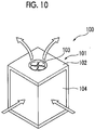
- a difference in the speed of the received blowing air occurs, for example, due to an air blowing unit 103 illustrated in Fig. 10 .
- the heat exchanger 100 of the embodiment has a casing 101 accommodating the heat exchanger 100 as illustrated in Fig. 10 .
- the casing 101 has a casing body 102, a ventilating unit 104, and the air blowing unit 103.
- the casing body 102 is a substantially rectangular parallelepiped box extending in the vertical direction, and has the ventilating unit 104, through which air can circulate inside and outside the casing body 102, for example, on two side surfaces next to each other, out of four side surfaces.
- the air blowing unit 103 formed of a fan that is rotatable about a vertical axis is provided on a top surface of the casing body 102. When the fan of the ventilating unit 104 operates, air in the casing body 102 is sent toward the outside of the casing 101, that is, from the lower side toward the upper side.
- air is sent from the outside of the casing body 102 into the casing body 102 via the ventilating unit 104.
- the ventilating unit 104 operates such that air is blown from above the casing 101
- the heat exchanger 100 disposed in the casing body 102 receives the blown air having a speed that differs according to the vertical direction. Accordingly, in the embodiment, the speed of blowing air received by the upper second tube group 26 is higher than the speed of blowing air received by the lower second tube group 25.
- the flow passage sectional area of the second connection pipe 70 is set so as to be larger than the flow passage sectional area of the first connection pipe 60 over the entire region in the extending direction of the first connection pipe 60 and the extending direction of the second connection pipe 70, as in the third embodiment.
- the flow passage sectional area of the first connection pipe 60 connected to the lower second header part 54 corresponding to the lower second tube group 25 that receives blowing air of a lower speed is set so as to be relatively smaller.
- the flow passage sectional area of the second connection pipe 70 connected to the upper second header part 55 corresponding to the upper second tube group 26, which receives blowing air of a higher speed and has a relatively larger number of the second heat transfer tubes 23, is set so as to be relatively larger.
- the heat exchange efficiency of the heat exchanger 100 as a whole can be improved by introducing a larger amount of refrigerants into the second header parts 53 connected to the upper second tube group 26 that receives blowing air of a higher speed.
- a heat exchanger 110 according to a fifth embodiment of the invention will be described with reference to Fig. 11 and Fig. 12 .
- the same configuration elements as the first embodiment will be assigned with the same reference signs as the first embodiment, and the detailed description thereof will be omitted.
- the heat exchanger 110 of the embodiment has three partition plates 58 provided in the turnback header 50. That is, the partition plates 58 are provided at intervals in the vertical direction, and accordingly, a region in the header 30 is partitioned into four regions in the vertical direction. Out of the four regions, a portion that includes the lowermost region is set as the first header part 52, as in the first embodiment. In addition, out of the four regions, portions that each include one of the three upper regions, excluding the lowermost region, are set as the second header parts 53. In the embodiment, one first header part 52 and three second header parts 53 are provided.
- connection pipes 120 including the connection pipe 120 that connects the first header part 52 and the lowermost second header part 53 together, out of the three second header parts 53, the connection pipe 120 that connects the first header part 52 and the middle second header part 53 together, out of the three second header parts 53, and the connection pipe 120 that connects the first header part 52 and the uppermost second header part 53 together, out of the three second header parts 53, are provided.
- a communication passage 121 that allows the first header part 52 to communicate with any one of the second header parts 53 is formed in each of the connection pipes 120.
- connection points of the connection pipes 120 to the first header part 52 are at the same vertical position, as in the first embodiment.
- the uniformization of mass flow rates of refrigerants introduced from the first header part 52 into the respective second header parts 53 can be achieved as in the first embodiment.
- the three second header parts 53 are provided in the embodiment, there may be four or more second header parts 53. In this case, also the number of the connection pipes 120 increases according to the number of the second header parts 53.
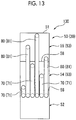
- a heat exchanger 130 according to a sixth embodiment of the invention will be described with reference to Fig. 13 .
- the same configuration elements as the first embodiment will be assigned with the same reference signs as the first embodiment, and the detailed description thereof will be omitted.
- the sixth embodiment is different from the first embodiment in that the plurality of first connection pipes 60 and the plurality of second connection pipes 70 are provided.
- the plurality of (three, in the embodiment) first connection pipes 60 are provided in the sixth embodiment. While the connection points of the first connection pipes 60 to the first header part 52 are at the same vertical position, the connection points of the first connection pipes to the lower second header part 54 are at positions different from each other in the vertical direction.
- the first-tier first connection pipe 60 is connected to a lower portion of the lower second header part 54
- the second-tier second connection pipe 70 is connected to a middle portion of the lower second header part 54
- the third-tier first connection pipe 60 is connected to an upper portion of the lower second header part 54.
- the plurality of (three, in the embodiment) second connection pipes 70 are also provided in the sixth embodiment. While the connection points of the second connection pipes 70 to the first header part 52 are at the same vertical position, the connection points of the second connection pipes to the upper second header part 55 are at positions different from each other in the vertical direction.
- the first-tier first connection pipe 60 is connected to a lower portion of the upper second header part 55
- the second-tier second connection pipe 70 is connected to a middle portion of the upper second header part 55
- the third-tier first connection pipe 60 is connected to an upper portion of the upper second header part 55.
- the uniformization of mass flow rates of refrigerants introduced into the lower second header part 54 and the upper second header part 55 can be achieved as in the first embodiment.
- refrigerants are introduced from a plurality of points, of which height positions are different from each other, to the first header part 52 and the second header parts 53.
- refrigerant being mixed in each of the first header part 52 and the second header parts 53 in the vertical direction, the homogenization of refrigerants in the first header part 52 and the second header parts 53 can be caused. Accordingly, the uniformization of mass flow rates of refrigerants introduced into the respective second heat transfer tubes 23 can be achieved.
- branch connection pipe 81 of the second embodiment may be applied to the third to fifth embodiments.
- the flow passage sectional areas of the first connection pipe 60 and the second connection pipe 70 may be adjusted according to the number of the second heat transfer tubes 23 configuring the second tube groups 24 and the amount of blowing air received by each of the second heat transfer tubes 23.
Landscapes
- Engineering & Computer Science (AREA)
- Mechanical Engineering (AREA)
- General Engineering & Computer Science (AREA)
- Physics & Mathematics (AREA)
- Thermal Sciences (AREA)
- Chemical & Material Sciences (AREA)
- Combustion & Propulsion (AREA)
- Heat-Exchange Devices With Radiators And Conduit Assemblies (AREA)
- Details Of Heat-Exchange And Heat-Transfer (AREA)
- Air Filters, Heat-Exchange Apparatuses, And Housings Of Air-Conditioning Units (AREA)
Abstract
Description
- The present invention relates to a heat exchanger and an air conditioner.
- This application claims priority from Japanese Patent Application No.
2016-038404 filed on February 29, 2016 - A heat exchanger, in which a plurality of heat transfer tubes extending in a horizontal direction are disposed at intervals in a vertical direction and a fan is provided on an outer surface of each heat transfer tube, is known as a heat exchanger of an air conditioner. Both ends of the plurality of heat transfer tubes are connected to a pair of headers extending in the vertical direction, respectively. Such a heat exchanger is configured such that a refrigerant, which is introduced into one header and is circulated in the other header via the heat transfer tubes, turns back at the other header to return to one header again via the heat transfer tubes, in order to secure a flow passage length for the refrigerant.
- The inside of the header at a turnback side is partitioned into a plurality of regions with a partition plate partitioning the inside of the header in the vertical direction. Accordingly, a refrigerant introduced in one region via the heat transfer tubes returns to one header on an entrance side via the plurality of heat transfer tubes connected to the other region after being introduced into the other region via a connection pipe.
- For example, a heat exchanger including a connection pipe which has one main pipe portion and branch pipe portions that extend so as to branch off into a plurality of portions from the main pipe portion is disclosed in PTL 1. In the heat exchanger, the main pipe portion is connected to a region in one header, and the branch pipe portions each are connected to any one of the plurality of other regions in the header. In a case where the heat exchanger is used as an evaporator, a refrigerant introduced in one region of the header via the heat transfer tubes is introduced into the plurality of other regions via the main pipe portion and the branch pipe portions of the connection pipe.
- [PTL 1] Japanese Unexamined Patent Application Publication No.
2015-55404 - However, in the heat exchanger in PTL 1, refrigerants having different degrees of dryness are introduced into the respective branch pipe portions in some cases when diverting refrigerants from the main pipe portion of the connection pipe to the branch pipe portions. That is, a large amount of liquid phase refrigerants flow into only some of a plurality of branch pipes in some cases according to the flow rate of a refrigerant and a branching direction, and thus there is a problem that a refrigerant is not uniformly diverted. In addition, a refrigerant in the connection pipe separates into a gas phase and a liquid phase in some cases according to a density difference between gas and liquid as well, and a refrigerant is diverted in some cases in a state where a deviation occurs in the flow rate or the degree of dryness.
- When a refrigerant is not uniformly diverted as described above, a change in a refrigerant distribution ratio at the time of diversion occurs since a flow aspect in each branch pipe differs according to a flow rate.
- For this reason, when the refrigerant is again introduced into the heat transfer tubes via the headers, there is a heat transfer tube through which a liquid phase refrigerant hardly passes, and thus a heat transfer region of the heat exchanger cannot be sufficiently used. As a consequence, for example, in a case where the heat exchanger is used as an air conditioner, a cooling performance and a heating performance deteriorate, and thus indoor amenity is impaired.
- An object of the invention is to provide a heat exchanger which can suppress a performance decrease and an air conditioner in which the heat exchanger is used. Solution to Problem
- In order to solve the problems, the invention adopts the following means.
- According to a first aspect of the invention, there is provided a heat exchanger including a first tube group that has a plurality of first heat transfer tubes which extend in a horizontal direction, allow a refrigerant to circulate therein, and are arranged at intervals in a vertical direction, a first header part that is in a cylindrical shape extending in the vertical direction and is connected to one end of each of the first heat transfer tubes of the first tube group in state of communicating, a plurality of second tube groups that have a plurality of second heat transfer tubes which extend in the horizontal direction, allow the refrigerant to circulate therein, and are arranged at intervals in the vertical direction, a plurality of second header parts, which are provided so as to correspond to the plurality of second tube groups and are in a cylindrical shape extending in the vertical direction and each of which is connected to one end of each of the second heat transfer tubes of the second tube groups in a communicating state, and a plurality of communication passages, which are provided so as to correspond to the plurality of second header parts and each have one end connected to the same vertical position of the first header part and the other end connected to any one of the second header parts such that the first header part communicates with each of the second header parts.
- In such a heat exchanger, the refrigerant introduced in the first header part via each first heat transfer tube of the first tube group is introduced into the communication passage connected to the same vertical position of the first header part. Herein, a liquid phase is likely to stay in a lower portion of the first header part due to a density difference between gas and liquid in the refrigerant and a gas phase is likely to stay in an upper portion of the first header part. For this reason, a difference in the gas-liquid ratios of refrigerants occurs in the vertical direction in the first header part. In the heat exchanger of the invention, the communication passages connected to the plurality of respective second header parts are connected to the same vertical position in the first header part. Therefore, refrigerants with almost the same gas phase-liquid phase ratio are introduced into each communication passage. For this reason, the uniformization of flow rates of refrigerants for the plurality of respective communication passages can be achieved. As a consequence, the flow rates of refrigerants introduced into the plurality of second heat transfer tubes can be uniformized.
- The heat exchanger may include a branch connection pipe that has a main pipe portion, of which one end is connected to the first header part and in which a plurality of split flow passages arranged in the horizontal direction are formed, and branch pipe portions, which branch off into a plurality of portions from the other end side of the main pipe portion, in which branch flow passages are formed so as to communicate with the split flow passages, and each of which is connected to each of the second header parts. Each of the communication passages may be a flow passage formed by each of the split flow passages and each of the branch flow passages.
- Consequently, construction is easy compared to a case where each communication passage is configured of a separate individual connection pipe since there is one construction point to the first header part in the case of the branch connection pipe.
- In the heat exchanger, the numbers of the second heat transfer tubes of the second tube groups may be different from each other, and the plurality of communication passages may be formed such that the communication passage connected to the second header part, to which the second tube group with a larger number of the second heat transfer tubes is connected, has a larger flow passage sectional area.
- Consequently, a larger amount of refrigerants are introduced into the second header part having a relatively larger number of the connected second heat transfer tubes. On the other hand, a smaller amount of refrigerants are introduced into the second header part having a relatively smaller number of the connected second heat transfer tubes. As a consequence, the uniformization of the amount of a refrigerant, which is diverted and introduced into each of the second heat transfer tubes, can be achieved.
- The heat exchanger may include an air blowing unit that blows air to each of the second tube groups, a speed of blowing air received by each of the second tube groups from the air blowing unit may be different for each of the second tube groups, and the plurality of communication passages may be formed such that the communication passage connected to the second header part, to which the second tube group receiving the blowing air of a higher speed is connected, has a larger flow passage sectional area.
- In such a heat exchanger, the higher the speed of blown air received by the second tube groups, the more heat exchange in the second tube groups is caused. Thus, the heat exchange efficiency of the heat exchanger as a whole can be improved by introducing a larger amount of refrigerants into the second header part connected to the second tube group that receives blowing air of which the speed is higher.
- The heat exchanger may further include another communication passage of which one end is connected to the first header part at the same height position as the communication passages connected to the first header part and the other end is connected to the second header part at a height position different from the communication passages connected to the second header parts such that the first header part communicates with any one of the plurality of second header parts.
- Consequently, refrigerants are introduced from a plurality of points different in the vertical direction into the second header parts. Thus, since the homogenization of gas-liquid ratio of refrigerants in the vertical direction in the second header parts can be achieved, the flow rate of the refrigerant diverted into the respective second heat transfer tubes can be uniformized.
- In the heat exchanger, a header that has a header body which is in a cylindrical shape extending in the vertical direction and a plurality of main partition plates that partition an inside of the header body into a plurality of regions in the vertical direction may be included, the first header part may be a portion that includes the lowermost region out of the plurality of regions in the header, and each of the second header parts may be a portion that includes any one of the regions excluding the lowermost region, out of the plurality of regions in the header.
- The heat exchanger having the first header part and the plurality of second header parts can be easily configured by forming the first header part and the plurality of second header parts with the main partition plate in one header part.
- According to a second aspect of the invention, there is provided an air conditioner including any one of the heat exchangers described above.
- Accordingly, a decrease in a heat exchange performance caused by inhomogeneous distribution of the refrigerant is suppressed, and thus the air conditioner with a high efficiency can be provided.
- The heat exchanger and the air conditioner of the invention can achieve the suppression of an efficiency decrease.
-
-
Fig. 1 is an overall configuration view of an air conditioner according to a first embodiment of the invention. -
Fig. 2 is a longitudinal sectional view of a heat exchanger according to the first embodiment of the invention. -
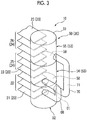
Fig. 3 is a perspective view of the heat exchanger according to the first embodiment of the invention. -
Fig. 4 is a side view of a turnback side header and a branch connection pipe of a heat exchanger according to a second embodiment of the invention. -
Fig. 5A is a view illustrating a sectional shape of a flow passage of a main pipe portion in the branch connection pipe of the heat exchanger according to the second embodiment of the invention. -
Fig. 5B is a view illustrating the sectional shape of the flow passage of the main pipe portion in the branch connection pipe of the heat exchanger according to the second embodiment of the invention. -
Fig. 6 is a perspective view of a heat exchanger according to a third embodiment of the invention. -
Fig. 7 is a side view of a turnback side header and a connection pipe of the heat exchanger according to the third embodiment of the invention. -
Fig. 8 is a perspective view of a heat exchanger according to a fourth embodiment of the invention. -
Fig. 9 is a side view of a turnback side header and a connection pipe of the heat exchanger according to the fourth embodiment of the invention. -
Fig. 10 is a perspective view illustrating an example of an air blowing unit according to the fourth embodiment of the invention. -
Fig. 11 is a perspective view of a heat exchanger according to a fifth embodiment of the invention. -
Fig. 12 is a side view of a turnback side header and a connection pipe of the heat exchanger according to the fifth embodiment of the invention. -
Fig. 13 is a side view of a turnback side header and a connection pipe of a heat exchanger according to a sixth embodiment of the invention. - Hereinafter, an air conditioner including a heat exchanger according to a first embodiment of the invention will be described with reference to
Figs. 1 to 5 . - As illustrated in
Fig. 1 , an air conditioner 1 includes acompressor 2, an indoor heat exchanger 3 (heat exchanger 10), an expansion valve 4, an outdoor heat exchanger 5 (heat exchanger 10), a four-way valve 6, and a pipe 7 that connects the configuration elements together, and a refrigerant circuit formed of the configuration elements is configured. - The
compressor 2 compresses a refrigerant and supplies the compressed refrigerant to the refrigerant circuit. - The
indoor heat exchanger 3 performs heat exchange between the refrigerant and indoor air. Theindoor heat exchanger 3 is used as an evaporator to absorb heat from the inside during cooling operation, and is used as a condenser to radiate heat to the inside during heating operation. - The expansion valve 4 reduces a pressure by expanding the high-pressure refrigerant liquefied by the condenser exchanging heat.
- The
outdoor heat exchanger 5 performs heat exchange between the refrigerant and outdoor air. The outdoor heat exchanger is used as a condenser to radiate heat to the outside during cooling operation and is used as an evaporator to absorb heat from the outside during heating operation. - The four-
way valve 6 switches between directions where a refrigerant circulates during heating operation and during cooling operation. Consequently, a refrigerant circulates in thecompressor 2, theoutdoor heat exchanger 5, the expansion valve 4, and theindoor heat exchanger 3 in this order during cooling operation. On the other hand, a refrigerant circulates in thecompressor 2, theindoor heat exchanger 3, the expansion valve 4, and theoutdoor heat exchanger 5 in this order during heating operation. - Next, the
heat exchangers 10 which are used as theindoor heat exchanger 3 and theoutdoor heat exchanger 5 will be described with reference toFig. 2 andFig. 3 . - The
heat exchangers 10 each include a plurality ofheat transfer tubes 20, a plurality offans 28, a pair ofheaders 30, afirst connection pipe 60, and asecond connection pipe 70. - The
heat transfer tubes 20 are tubular members linearly extending in a horizontal direction, and flow passages through which a refrigerant circulates are formed therein. The plurality ofheat transfer tubes 20 are arranged at intervals in a vertical direction, and are disposed so as to be parallel to each other. - In the embodiment, the
heat transfer tubes 20 each have a flat tubular shape, and the plurality of flow passages arranged in the horizontal direction orthogonal to an extending direction of theheat transfer tubes 20 are formed inside theheat transfer tubes 20. The plurality of flow passages are arranged so as to be parallel to each other. Consequently, a sectional shape orthogonal to the extending direction of theheat transfer tubes 20 is a flat shape of which a longitudinal direction is the horizontal direction orthogonal to the extending direction of theheat transfer tubes 20. - The
fans 28 each are disposed between theheat transfer tubes 20 arranged as described above, and extend in a so-called corrugated shape so as to be alternately in contact with the vertically nearbyheat transfer tubes 20 as facing the extending direction of each of theheat transfer tubes 20 in the embodiment. Without being limited thereto, the shapes of thefans 28 may be any shape insofar as the fans are provided so as to protrude from outer peripheral surfaces of theheat transfer tubes 20. - At both ends of the plurality of
heat transfer tubes 20, the pair ofheaders 30 is provided such that theheat transfer tubes 20 are sandwiched therebetween. One of the pair ofheaders 30 is set as anentrance side header 40, which is an entrance of a refrigerant from the outside into theheat exchanger 10, and the other one is set as aturnback side header 50 for a refrigerant to turn back in theheat exchanger 10. - The
entrance side header 40 is a cylindrical member extending in the vertical direction. An upper end and a lower end of the entrance side header are closed and the inside of the entrance side header is partitioned into two upper and lower regions with apartition plate 41. The lower region partitioned with thepartition plate 41 is set as alower entry region 42 and the upper region is set as anupper entry region 43. Thelower entry region 42 and theupper entry region 43 are in a state of not communicating with each other in theentrance header 40. Thelower entry region 42 and theupper entry region 43 each are connected to the pipe 7 configuring the refrigerant circuit. - Herein, out of the plurality of
heat transfer tubes 20, theheat transfer tubes 20 connected to thelower entry region 42 in a communicating state are set as firstheat transfer tubes 21, and theheat transfer tubes 20 connected to theupper entry region 43 in a communicating state are set as secondheat transfer tubes 23. - The
turnback side header 50 includes aheader body 51 andmain partition plates 58. - The
header body 51 is a cylindrical member extending in the vertical direction, and an upper end and a lower end of the header body are closed. Themain partition plates 58 are provided in theheader body 51, and partition a space in theheader body 51 into upper and lower regions. In the embodiment, the twomain partition plates 58 are disposed in theheader body 51 at an interval in the vertical direction. Accordingly, the inside of theheader body 51 is partitioned into three regions vertically arranged. - Out of the three regions in the
header body 51, a portion that includes the lowermost region is set as afirst header part 52. In addition, out of the three regions, portions that each include one of the two upper regions, excluding the lowermost region, are set assecond header parts 53. That is, in the embodiment, onefirst header part 52 and twosecond header parts 53 each of which has a space inside therein are formed in theturnback side header 50 by the inside of theheader body 51 being partitioned with the twomain partition plates 58. In other words, theturnback side header 50 is configured with onefirst header part 52 and twosecond header parts 53. - The first
heat transfer tubes 21 each are connected to thefirst header part 52 so as to be in a communicating state with the inside of thefirst header part 52. Afirst tube group 22 is configured with the plurality of firstheat transfer tubes 21. In other words, theheat transfer tubes 20 connected to thefirst header part 52 are set as the firstheat transfer tubes 21. - The second
heat transfer tubes 23 each are connected to one of thesecond header parts 53 so as to be in a communicating state with one of the insides of thesecond header parts 53. That is, theheat transfer tubes 20 connected to thesecond header parts 53 are set as the secondheat transfer tubes 23. -
Second tube groups 24 each are configured with the plurality of secondheat transfer tubes 23 each of which is connected to one of thesecond header parts 53. That is, since there are twosecond header parts 53 in the embodiment, twosecond tube groups 24 are configured so as to be paired with the twosecond header parts 53. - Hereinafter, out of the two upper and lower
second header parts 53, thesecond header part 53 disposed on a lower side will be referred to as a lowersecond header part 54, and thesecond header part 53 disposed on an upper side will be referred to as an uppersecond header part 55, in the embodiment. - In addition, the
second tube group 24 configured with the secondheat transfer tubes 23 connected to the lowersecond header part 54 will be referred to as a lowersecond tube group 25, and thesecond tube group 24 configured with the secondheat transfer tubes 23 connected to the uppersecond header part 55 will be referred to as an uppersecond tube group 26. - The
first connection pipe 60 is a tubular member in which a flow passage is formed. One end of the first connection pipe is connected to thefirst header part 52 in a communicating state with the inside of thefirst header part 52, and the other end is connected to the lowersecond header part 54 in a communicating state with the inside of the lowersecond header part 54. More specifically, one end of thefirst connection pipe 60 is connected to an upper portion of thefirst header part 52. In addition, the other end of thefirst connection pipe 60 is connected to a lower portion of the lowersecond header part 54. In the embodiment, the flow passage in thefirst connection pipe 60 is set as a first communication passage 61 (communication passage) that connects thefirst header part 52 and the lowersecond header part 54 together. - The
second connection pipe 70 is a tubular member in which a flow passage is formed. One end of the second connection pipe is connected to thefirst header part 52 in a communicating state with the inside of thefirst header part 52 as in thefirst connection pipe 60. On the other hand, the other end of thesecond connection pipe 70 is connected to the uppersecond header part 55 in a communicating state with the inside of the uppersecond header part 55, unlike thefirst connection pipe 60. More specifically, one end of thesecond connection pipe 70 is connected to the upper portion of thefirst header part 52. In addition, the other end of thefirst connection pipe 60 is connected to a lower portion of the uppersecond header part 55. In the embodiment, the flow passage in thesecond connection pipe 70 is set as a second communication passage 71 (communication passage) that connects thefirst header part 52 and the uppersecond header part 55 together. - Herein, a connection point of the
first connection pipe 60 to thefirst header part 52 and a connection point of thesecond connection pipe 70 to thefirst header part 52 are at the same vertical position, in the embodiment. That is, the connection point of thefirst connection pipe 60 to thefirst header part 52 is disposed so as to be adjacent to or to be spaced apart from the connection point of thesecond connection pipe 70 to thefirst header part 52 in the horizontal direction, and has the same vertical position as the connection point of the second connection pipe to the first header part. - "The same vertical position" is not limited to a case where the vertical position of a center of the connection point of the
first connection pipe 60 to thefirst header part 52 and the vertical position of a center of the connection point of thesecond connection pipe 70 to thefirst header part 52 are the same, it is sufficient that at least a part of the vertical position of the connection point of thefirst connection pipe 60 to thefirst header part 52 and a part of the vertical position of the connection point of thesecond connection pipe 70 to thefirst header part 52 overlap each other in the vertical direction. - Next, operation and effects in a case where the
heat exchanger 10 is used as an evaporator will be described. - In a case where the
heat exchanger 10 is theindoor heat exchanger 3, the air conditioner 1 is used as an evaporator during cooling operation, and in a case where the heat exchanger is theoutdoor heat exchanger 5, the air conditioner 1 is used as an evaporator during heating operation. - When the
heat exchanger 10 is used as an evaporator, a gas-liquid two phase refrigerant having a high liquid phase content is supplied from the pipe 7 to thelower entry region 42 of theentrance side header 40 illustrated inFig. 2 . The refrigerant is divided and supplied to the plurality of firstheat transfer tubes 21 in thelower entry region 42, and exchanges heat with the external atmosphere of the firstheat transfer tubes 21 in the process of circulating in the firstheat transfer tubes 21, thereby causing evaporation. Consequently, the refrigerant supplied from the firstheat transfer tubes 21 into thefirst header part 52 of theturnback side header 50 becomes a gas-liquid two phase refrigerant, in which the proportion of a liquid phase has dropped, by some of the refrigerant changing from the liquid phase to a gas phase. - Out of gas-liquid two phase refrigerants supplied into the
first header part 52, a refrigerant with a high liquid phase content and a high density gathers at the lower portion of thefirst header part 52 due to gravity, and a refrigerant with a high gas phase content and a low density gathers at the upper portion of thefirst header part 52. That is, in thefirst header part 52, the gas-liquid ratio of a refrigerant, that is, the density of the refrigerant differs according to a vertical position. Herein, if the connection position of thefirst connection pipe 60 to thefirst header part 52 and the connection position of thesecond connection pipe 70 to thefirst header part 52 are different from each other in the vertical direction, the gas-liquid ratios of refrigerants introduced into thefirst connection pipe 60 and thesecond connection pipe 70 are different from each other. As a consequence, as a result of a refrigerant with a high density being introduced into one of thefirst connection pipe 60 and thesecond connection pipe 70, which is connected to a lower part of thefirst header part 52, the mass flow rate of the refrigerant becomes higher. On the other hand, as a result of a refrigerant with a low density being introduced into a connection pipe connected to a higher part of the first header part, the mass flow rate of the refrigerant becomes lower. - On the contrary, the connection position of the
first connection pipe 60 to thefirst header part 52 and the connection position of thesecond connection pipe 70 to thefirst header part 52 are at the same vertical position, in the embodiment. For this reason, refrigerants having almost the same gas-liquid ratio are introduced into thefirst connection pipe 60 and thesecond connection pipe 70 respectively. As a consequence, the gas-liquid ratios of the refrigerants introduced into the lowersecond header part 54 and the uppersecond header part 55 via thefirst connection pipe 60 and thesecond connection pipe 70 respectively are almost the same. That is, the uniformization of the mass flow rates of refrigerants circulating in thefirst connection pipe 60 and thesecond connection pipe 70 is achieved. - After then, a refrigerant introduced in the lower
second header part 54 and the uppersecond header part 55 via thefirst connection pipe 60 or thesecond connection pipe 70 is diverted to the plurality of secondheat transfer tubes 23 connected thereto and circulates in the secondheat transfer tubes 23. Then, the refrigerant again causes evaporation by exchanging heat with the external atmosphere of the secondheat transfer tubes 23 in the process of circulating in the secondheat transfer tubes 23. Consequently, in the secondheat transfer tubes 23, the remaining liquid phase in the refrigerant changes to the gas phase and the refrigerant in a gas phase state is supplied to theupper entry region 43 of theentrance side header 40. Then, the refrigerant is introduced from theupper entry region 43 to the pipe 7, thereby circulating in the refrigerant circuit. - As described above, in the
heat exchanger 10 of the invention, thefirst communication passage 61 of thefirst connection pipe 60 and thesecond communication passage 71 of thesecond connection pipe 70, each of which is connected to one of the plurality ofsecond header parts 53, are connected to thefirst header part 52 at the same vertical position. Therefore, refrigerants with almost the same gas phase-liquid phase ratio are introduced into the respective communication passages. For this reason, the uniformization of flow rates of refrigerants for the plurality of respective communication passages can be achieved. As a consequence, for example, in a case where theheat exchanger 10 is used as an air conditioner, a cooling performance and a heating performance are not impaired. - Next, a
heat exchanger 80 according to a second embodiment of the invention will be described with reference toFig. 4 ,Fig. 5A, and Fig. 5B . In the second embodiment, the same configuration elements as the first embodiment will be assigned with the same reference signs as the first embodiment, and the detailed description thereof will be omitted. - As illustrated in
Fig. 4 , theheat exchanger 80 of the second embodiment is different from the heat exchanger of the first embodiment in that onebranch connection pipe 81 is included instead of thefirst connection pipe 60 and thesecond connection pipe 70 of the first embodiment. - The
branch connection pipe 81 has amain pipe portion 82 and a plurality of (two, in the embodiment)branch pipe portions 85. - One end of the
main pipe portion 82 is connected to thefirst header part 52. In thefirst header part 52, two splitflow passages 83, which are formed by splitting the inside of thefirst header part 52 in the horizontal direction into two regions, are formed as illustrated inFig. 5A and Fig. 5B . The split flowpassages 83 are arranged in the horizontal direction so as to extend from one end to the other end of themain pipe portion 82. As illustrated inFig. 5A , themain pipe portion 82 may have a structure in which the two splitflow passages 83 are formed by providing asplit wall portion 84 in the middle of a circular section of the flow passage in the horizontal direction. In addition, as illustrated inFig. 5B , the main pipe portion may have a structure in which thesplit flow passages 83 obtained by linearly cutting out a part of the circular section of the flow passage are provided so as to be arranged side by side via thesplit wall portion 84 configuring the linear portion. - The two
branch pipe portions 85 are provided so as to branch off into a plurality of portions from the other end side of themain pipe portion 82. Thebranch pipe portions 85 are connected to the lowersecond header part 54 and the uppersecond header part 55 respectively. In addition,branch flow passages 86, which are flow passages inside the respectivebranch pipe portions 85, communicate with thesplit flow passages 83 in themain pipe portion 82 in a one-to-one relationship. Accordingly, out of the two splitflow passages 83 of themain pipe portion 82, onesplit flow passage 83 is in a communicating state with the inside of the lowersecond header part 54 via onebranch flow passage 86, that is, thefirst communication passage 61 that allows thefirst header part 52 to communicate with the lowersecond header part 54 by means of onesplit flow passage 83 and onebranch flow passage 86 is formed. In addition, the othersplit flow passage 83 is in a communicating state with the inside of the uppersecond header part 55 via the otherbranch flow passage 86, that is, thesecond communication passage 71 that allows the inside of thefirst header part 52 to communicate with the uppersecond header part 55 by means of the othersplit flow passage 83 and the otherbranch flow passage 86 is formed. - In such a
heat exchanger 80 of the second embodiment, the two splitflow passages 83 in themain pipe portion 82 of thebranch connection pipe 81 are arranged in the horizontal direction side by side. Therefore, refrigerants with almost the same density are introduced into the two splitflow passages 83. Then, the refrigerants are introduced into the lowersecond header part 54 and the uppersecond header part 55 via the respectivebranch flow passages 86. Thus, the uniformization of mass flow rates of refrigerants introduced into the lowersecond header part 54 and the uppersecond header part 55 can be achieved as in the first embodiment. - In addition, since there is only one connection point to the
first header part 52, construction can be performed more easily compared to a case where thefirst connection pipe 60 and thesecond connection pipe 70 are separately provided as in the first embodiment. - Next, a
heat exchanger 90 according to a third embodiment of the invention will be described with reference toFig. 6 andFig. 7 . In the third embodiment, the same configuration elements as the first embodiment will be assigned with the same reference signs as the first embodiment, and the detailed description thereof will be omitted. - As illustrated in
Fig. 6 andFig. 7 , theheat exchanger 90 of the third embodiment is different from the first embodiment in that the number of the secondheat transfer tubes 23 of the lowersecond tube group 25 and the number of the secondheat transfer tubes 23 of the uppersecond tube group 26 are different from each other and the flow passage sectional areas of thefirst connection pipe 60 and thesecond connection pipe 70 are different from each other. - The
heat exchanger 90 of the embodiment is provided such that the number of the secondheat transfer tubes 23 of the uppersecond tube group 26 is larger than the number of the secondheat transfer tubes 23 of the lowersecond tube group 25. Since respective intervals between the secondheat transfer tubes 23 in the vertical direction are the same, the uppersecond header part 55 has a larger dimension in the vertical direction than the lowersecond header part 54 has according to a difference between the number of the secondheat transfer tubes 23 of the lowersecond tube group 25 and the number of the secondheat transfer tubes 23 of the uppersecond tube group 26. - The flow passage sectional area of the
second connection pipe 70 is set so as to be larger than the flow passage sectional area of thefirst connection pipe 60 over the entire region in an extending direction of thefirst connection pipe 60 and an extending direction of thesecond connection pipe 70. The flow passage sectional areas are the areas of the sections, which are orthogonal to the extending direction of thefirst connection pipe 60 and the extending direction of thesecond connection pipe 70, of the flow passages. - As described above, in the embodiment, the flow passage sectional area of the
first connection pipe 60 connected to the lowersecond header part 54 corresponding to the lowersecond tube group 25 having a relatively smaller number of the secondheat transfer tubes 23 is set so as to be relatively smaller. In addition, the flow passage sectional area of thesecond connection pipe 70 connected to the uppersecond header part 55 corresponding to the uppersecond tube group 26 having a relatively larger number of the secondheat transfer tubes 23 is set so as to be relatively larger. - In the
heat exchanger 90 of the third embodiment, a larger amount of refrigerants are introduced into the uppersecond header part 55 having a relatively larger number of the connected secondheat transfer tubes 23. On the other hand, a smaller amount of refrigerants are introduced into the lowersecond header part 54 having a relatively smaller number of the connected secondheat transfer tubes 23. The larger the number of the connected secondheat transfer tubes 23, the larger amount of refrigerants circulate in the secondheat transfer tubes 23 and thus heat exchange can be caused. Therefore, the uniformization of mass flow rates of refrigerants circulating in the secondheat transfer tubes 23 as a whole can be achieved. - Next, a
heat exchanger 100 according to a fourth embodiment of the invention will be described with reference toFig. 8 to Fig. 10 . In the third embodiment, the same configuration elements as the first embodiment will be assigned with the same reference signs as the first embodiment, and the detailed description thereof will be omitted. - As illustrated in
Fig. 8 andFig. 9 , theheat exchanger 100 of the fourth embodiment is different from the first embodiment in that the speed of blowing air received by the secondheat transfer tubes 23 of the lowersecond tube group 25 and the speed of blowing air received by the secondheat transfer tubes 23 of the uppersecond tube group 26 are different from each other and the flow passage sectional areas of thefirst connection pipe 60 and thesecond connection pipe 70 are different from each other. - In the embodiment, the speed of blowing air received by the upper
second tube group 26 is higher than the speed of blowing air received by the lowersecond tube group 25. A difference in the speed of the received blowing air occurs, for example, due to anair blowing unit 103 illustrated inFig. 10 . - That is, the
heat exchanger 100 of the embodiment has acasing 101 accommodating theheat exchanger 100 as illustrated inFig. 10 . - The
casing 101 has acasing body 102, aventilating unit 104, and theair blowing unit 103. Thecasing body 102 is a substantially rectangular parallelepiped box extending in the vertical direction, and has theventilating unit 104, through which air can circulate inside and outside thecasing body 102, for example, on two side surfaces next to each other, out of four side surfaces. Theair blowing unit 103 formed of a fan that is rotatable about a vertical axis is provided on a top surface of thecasing body 102. When the fan of theventilating unit 104 operates, air in thecasing body 102 is sent toward the outside of thecasing 101, that is, from the lower side toward the upper side. Conversely, air is sent from the outside of thecasing body 102 into thecasing body 102 via theventilating unit 104. As described above, when theventilating unit 104 operates such that air is blown from above thecasing 101, theheat exchanger 100 disposed in thecasing body 102 receives the blown air having a speed that differs according to the vertical direction. Accordingly, in the embodiment, the speed of blowing air received by the uppersecond tube group 26 is higher than the speed of blowing air received by the lowersecond tube group 25. - In the embodiment, the flow passage sectional area of the
second connection pipe 70 is set so as to be larger than the flow passage sectional area of thefirst connection pipe 60 over the entire region in the extending direction of thefirst connection pipe 60 and the extending direction of thesecond connection pipe 70, as in the third embodiment. - As described above, in the embodiment, the flow passage sectional area of the
first connection pipe 60 connected to the lowersecond header part 54 corresponding to the lowersecond tube group 25 that receives blowing air of a lower speed is set so as to be relatively smaller. In addition, the flow passage sectional area of thesecond connection pipe 70 connected to the uppersecond header part 55 corresponding to the uppersecond tube group 26, which receives blowing air of a higher speed and has a relatively larger number of the secondheat transfer tubes 23, is set so as to be relatively larger. - In such a
heat exchanger 100, the higher the speed of blowing air received by thesecond tube groups 24, the more heat exchange in thesecond tube groups 24 is caused. Thus, the heat exchange efficiency of theheat exchanger 100 as a whole can be improved by introducing a larger amount of refrigerants into thesecond header parts 53 connected to the uppersecond tube group 26 that receives blowing air of a higher speed. - Next, a
heat exchanger 110 according to a fifth embodiment of the invention will be described with reference toFig. 11 andFig. 12 . In the fifth embodiment, the same configuration elements as the first embodiment will be assigned with the same reference signs as the first embodiment, and the detailed description thereof will be omitted. - As illustrated in
Fig. 11 andFig. 12 , theheat exchanger 110 of the embodiment has threepartition plates 58 provided in theturnback header 50. That is, thepartition plates 58 are provided at intervals in the vertical direction, and accordingly, a region in theheader 30 is partitioned into four regions in the vertical direction. Out of the four regions, a portion that includes the lowermost region is set as thefirst header part 52, as in the first embodiment. In addition, out of the four regions, portions that each include one of the three upper regions, excluding the lowermost region, are set as thesecond header parts 53. In the embodiment, onefirst header part 52 and threesecond header parts 53 are provided. - In the embodiment, in total three
connection pipes 120, including theconnection pipe 120 that connects thefirst header part 52 and the lowermostsecond header part 53 together, out of the threesecond header parts 53, theconnection pipe 120 that connects thefirst header part 52 and the middlesecond header part 53 together, out of the threesecond header parts 53, and theconnection pipe 120 that connects thefirst header part 52 and the uppermostsecond header part 53 together, out of the threesecond header parts 53, are provided. Acommunication passage 121 that allows thefirst header part 52 to communicate with any one of thesecond header parts 53 is formed in each of theconnection pipes 120. - In addition, connection points of the
connection pipes 120 to thefirst header part 52 are at the same vertical position, as in the first embodiment. - In such a
heat exchanger 110, the uniformization of mass flow rates of refrigerants introduced from thefirst header part 52 into the respectivesecond header parts 53 can be achieved as in the first embodiment. - Although an example in which the three
second header parts 53 are provided is described in the embodiment, there may be four or moresecond header parts 53. In this case, also the number of theconnection pipes 120 increases according to the number of thesecond header parts 53. - Next, a
heat exchanger 130 according to a sixth embodiment of the invention will be described with reference toFig. 13 . In the sixth embodiment, the same configuration elements as the first embodiment will be assigned with the same reference signs as the first embodiment, and the detailed description thereof will be omitted. - The sixth embodiment is different from the first embodiment in that the plurality of
first connection pipes 60 and the plurality ofsecond connection pipes 70 are provided. - That is, the plurality of (three, in the embodiment)
first connection pipes 60 are provided in the sixth embodiment. While the connection points of thefirst connection pipes 60 to thefirst header part 52 are at the same vertical position, the connection points of the first connection pipes to the lowersecond header part 54 are at positions different from each other in the vertical direction. In the embodiment, out of the threefirst connection pipes 60, the first-tierfirst connection pipe 60 is connected to a lower portion of the lowersecond header part 54, the second-tiersecond connection pipe 70 is connected to a middle portion of the lowersecond header part 54, and the third-tierfirst connection pipe 60 is connected to an upper portion of the lowersecond header part 54. - In addition, the plurality of (three, in the embodiment)
second connection pipes 70 are also provided in the sixth embodiment. While the connection points of thesecond connection pipes 70 to thefirst header part 52 are at the same vertical position, the connection points of the second connection pipes to the uppersecond header part 55 are at positions different from each other in the vertical direction. In the embodiment, out of the threefirst connection pipes 60, the first-tierfirst connection pipe 60 is connected to a lower portion of the uppersecond header part 55, the second-tiersecond connection pipe 70 is connected to a middle portion of the uppersecond header part 55, and the third-tierfirst connection pipe 60 is connected to an upper portion of the uppersecond header part 55. - In such a
heat exchanger 130, the uniformization of mass flow rates of refrigerants introduced into the lowersecond header part 54 and the uppersecond header part 55 can be achieved as in the first embodiment. - In particular, in the embodiment, refrigerants are introduced from a plurality of points, of which height positions are different from each other, to the
first header part 52 and thesecond header parts 53. For this reason, by a refrigerant being mixed in each of thefirst header part 52 and thesecond header parts 53 in the vertical direction, the homogenization of refrigerants in thefirst header part 52 and thesecond header parts 53 can be caused. Accordingly, the uniformization of mass flow rates of refrigerants introduced into the respective secondheat transfer tubes 23 can be achieved. - Although the embodiments of the invention are described, the invention is not limited thereto, and can be modified as appropriate without departing from the technical scope of the invention.
- For example, the
branch connection pipe 81 of the second embodiment may be applied to the third to fifth embodiments. - In addition, by combining the third embodiment with the fourth embodiment, the flow passage sectional areas of the
first connection pipe 60 and thesecond connection pipe 70 may be adjusted according to the number of the secondheat transfer tubes 23 configuring thesecond tube groups 24 and the amount of blowing air received by each of the secondheat transfer tubes 23. -
- 1
- air conditioner
- 2
- compressor
- 3
- indoor heat exchanger
- 4
- expansion valve
- 5
- outdoor heat exchanger
- 6
- four-way valve
- 7
- pipe
- 10
- heat exchanger
- 20
- heat transfer tube
- 21
- first heat transfer tube
- 22
- first tube group
- 23
- second heat transfer tube
- 24
- second tube group
- 25
- lower second tube group
- 26
- upper second tube group
- 28
- fan
- 30
- header
- 40
- entrance side header
- 41
- partition plate
- 42
- lower entry region
- 43
- upper entry region
- 50
- turnback side header
- 51
- header body
- 52
- first header part
- 53
- second header part
- 54
- lower second header part
- 55
- upper second header part
- 58
- main partition plate
- 60
- first connection pipe
- 61
- first communication passage
- 70
- second connection pipe
- 71
- second communication passage
- 80
- heat exchanger
- 81
- branch connection pipe
- 82
- main pipe portion
- 83
- split flow passage
- 84
- split wall portion
- 85
- branch pipe portion
- 86
- branch flow passage
- 90
- heat exchanger
- 100
- heat exchanger
- 101
- casing
- 102
- casing body
- 103
- air blowing unit
- 104
- ventilating unit
- 110
- heat exchanger
- 120
- connection pipe
- 121
- communication passage
- 130
- heat exchanger
Claims (7)
- A heat exchanger comprising:a first tube group that has a plurality of first heat transfer tubes which extend in a horizontal direction, allow a refrigerant to circulate therein, and are arranged at intervals in a vertical direction;a first header part that is in a cylindrical shape extending in the vertical direction and is connected to one end of each of the first heat transfer tubes of the first tube group in a communicating state;a plurality of second tube groups that have a plurality of second heat transfer tubes which extend in the horizontal direction, allow the refrigerant to circulate therein, and are arranged at intervals in the vertical direction;a plurality of second header parts, which are provided so as to correspond to the plurality of second tube groups and are in a cylindrical shape extending in the vertical direction and each of which is connected to one end of each of the second heat transfer tubes of the second tube groups in a communicating state; anda plurality of communication passages, which are provided so as to correspond to the plurality of second header parts and each have one end connected to the same vertical position of the first header part and the other end connected to any one of the second header parts such that the first header part communicates with each of the second header parts.
- The heat exchanger according to Claim 1, further comprising:a branch connection pipe that has a main pipe portion, of which one end is connected to the first header part and in which a plurality of split flow passages arranged in the horizontal direction are formed, and branch pipe portions, which branch off into a plurality of portions from the other end side of the main pipe portion, in which branch flow passages are formed so as to communicate with the split flow passages, and each of which is connected to any one of the second header parts,wherein each of the communication passages is a flow passage formed by each of the split flow passages and each of the branch flow passages.
- The heat exchanger according to Claim 1 or 2,
wherein the numbers of the second heat transfer tubes of the second tube groups are different from each other, and
the communication passages are formed such that the communication passage connected to the second header part, to which the second tube group with a larger number of the second heat transfer tubes is connected, has a larger flow passage sectional area. - The heat exchanger according to any one of Claims 1 to 3, further comprising:an air blowing unit that blows air to each of the second tube groups,wherein a speed of blowing air received by each of the second tube groups from the air blowing unit is different for each of the second tube groups, andthe communication passages are formed such that the communication passage connected to the second header part, to which the second tube group receiving the blowing air of a higher speed is connected, has a larger flow passage sectional area.
- The heat exchanger according to any one of Claims 1 to 4, further comprising:
another communication passage of which one end is connected to the first header part at the same height position as the communication passages connected to the first header part and the other end is connected to the second header part at a height position different from the communication passages connected to the second header parts such that the first header part communicates with any one of the plurality of second header parts. - The heat exchanger according to any one of Claims 1 to 5, further comprising:a header that has a header body which is in a cylindrical shape extending in the vertical direction and a plurality of main partition plates that partition an inside of the header body into a plurality of regions in the vertical direction,wherein the first header part is a portion that includes the lowermost region out of the plurality of regions in the header, andeach of the second header parts is a portion that includes any one of the regions excluding the lowermost region, out of the plurality of regions in the header.
- An air conditioner comprising the heat exchanger according to any one of Claims 1 to 6.
Applications Claiming Priority (2)
| Application Number | Priority Date | Filing Date | Title |
|---|---|---|---|
| JP2016038404A JP6742112B2 (en) | 2016-02-29 | 2016-02-29 | Heat exchanger and air conditioner |
| PCT/JP2017/000974 WO2017149950A1 (en) | 2016-02-29 | 2017-01-13 | Heat exchanger and air conditioner |
Publications (2)
| Publication Number | Publication Date |
|---|---|
| EP3355023A1 true EP3355023A1 (en) | 2018-08-01 |
| EP3355023A4 EP3355023A4 (en) | 2018-12-26 |
Family
ID=59742708
Family Applications (1)
| Application Number | Title | Priority Date | Filing Date |
|---|---|---|---|
| EP17759422.3A Withdrawn EP3355023A4 (en) | 2016-02-29 | 2017-01-13 | Heat exchanger and air conditioner |
Country Status (5)
| Country | Link |
|---|---|
| EP (1) | EP3355023A4 (en) |
| JP (1) | JP6742112B2 (en) |
| CN (1) | CN108351188A (en) |
| AU (1) | AU2017228091B2 (en) |
| WO (1) | WO2017149950A1 (en) |
Families Citing this family (5)
| Publication number | Priority date | Publication date | Assignee | Title |
|---|---|---|---|---|
| JP2019100568A (en) * | 2017-11-29 | 2019-06-24 | 株式会社デンソー | Heat exchanger |
| KR102063630B1 (en) * | 2018-01-22 | 2020-01-08 | 엘지전자 주식회사 | Outdoor Heat exchanger |
| CN112413931B (en) * | 2020-11-30 | 2025-05-16 | 珠海格力电器股份有限公司 | Heat exchanger and heat pump system |
| WO2023281731A1 (en) * | 2021-07-09 | 2023-01-12 | 三菱電機株式会社 | Heat exchanger and air conditioner |
| JP7392757B2 (en) * | 2022-03-30 | 2023-12-06 | 株式会社富士通ゼネラル | Air conditioner indoor unit |
Family Cites Families (8)
| Publication number | Priority date | Publication date | Assignee | Title |
|---|---|---|---|---|
| JP2543965Y2 (en) * | 1990-06-04 | 1997-08-13 | 東洋ラジエーター株式会社 | Branch structure of heat exchanger |
| US9651317B2 (en) * | 2011-01-21 | 2017-05-16 | Daikin Industries, Ltd. | Heat exchanger and air conditioner |
| JP5609916B2 (en) * | 2012-04-27 | 2014-10-22 | ダイキン工業株式会社 | Heat exchanger |
| JP2014137177A (en) * | 2013-01-16 | 2014-07-28 | Daikin Ind Ltd | Heat exchanger and refrigerator |
| JP5761252B2 (en) * | 2013-05-22 | 2015-08-12 | ダイキン工業株式会社 | Heat exchanger |
| JP2015052440A (en) * | 2013-09-09 | 2015-03-19 | ダイキン工業株式会社 | Heat exchanger |
| EP3032182B1 (en) * | 2013-09-11 | 2018-09-05 | Daikin Industries, Ltd. | Heat exchanger and air conditioner |
| EP3147591B1 (en) * | 2014-05-19 | 2022-04-13 | Mitsubishi Electric Corporation | Air-conditioning device |
-
2016
- 2016-02-29 JP JP2016038404A patent/JP6742112B2/en active Active
-
2017
- 2017-01-13 AU AU2017228091A patent/AU2017228091B2/en active Active
- 2017-01-13 EP EP17759422.3A patent/EP3355023A4/en not_active Withdrawn
- 2017-01-13 WO PCT/JP2017/000974 patent/WO2017149950A1/en not_active Ceased
- 2017-01-13 CN CN201780003725.8A patent/CN108351188A/en active Pending
Also Published As
| Publication number | Publication date |
|---|---|
| EP3355023A4 (en) | 2018-12-26 |
| JP6742112B2 (en) | 2020-08-19 |
| JP2017155993A (en) | 2017-09-07 |
| AU2017228091A1 (en) | 2018-05-10 |
| CN108351188A (en) | 2018-07-31 |
| AU2017228091B2 (en) | 2019-07-18 |
| WO2017149950A1 (en) | 2017-09-08 |
Similar Documents
| Publication | Publication Date | Title |
|---|---|---|
| EP3425321B1 (en) | Heat exchanger and air conditioner | |
| EP3425320A1 (en) | Heat exchanger and air conditioner | |
| EP3037773B1 (en) | Heat exchanger, air conditioner, refrigeration cycle device, and method for producing heat exchanger | |
| US9518788B2 (en) | Heat exchanger | |
| AU2017228091B2 (en) | Heat exchanger and air conditioner | |
| US10309701B2 (en) | Heat exchanger and air conditioner | |
| US20160327343A1 (en) | Heat exchanger of air conditioner | |
| US10041710B2 (en) | Heat exchanger and air conditioner | |
| EP2728270B1 (en) | Outdoor machine of refrigeration device | |
| EP3473963A1 (en) | Heat exchanger and air conditioner | |
| EP3382316B1 (en) | Heat exchanger and air conditioner | |
| EP3376149B1 (en) | Heat exchanger and air conditioner | |
| US20180299203A1 (en) | Heat exchanger and refrigeration cycle apparatus | |
| WO2020039513A1 (en) | Heat exchanger and air conditioner | |
| WO2023148841A1 (en) | Heat exchanger and air-conditioning device | |
| JP6853867B2 (en) | Heat exchanger and air conditioner | |
| WO2025104801A1 (en) | Heat exchanger and air conditioner |
Legal Events
| Date | Code | Title | Description |
|---|---|---|---|
| STAA | Information on the status of an ep patent application or granted ep patent |
Free format text: STATUS: THE INTERNATIONAL PUBLICATION HAS BEEN MADE |
|
| PUAI | Public reference made under article 153(3) epc to a published international application that has entered the european phase |
Free format text: ORIGINAL CODE: 0009012 |
|
| STAA | Information on the status of an ep patent application or granted ep patent |
Free format text: STATUS: REQUEST FOR EXAMINATION WAS MADE |
|
| 17P | Request for examination filed |
Effective date: 20180425 |
|
| AK | Designated contracting states |
Kind code of ref document: A1 Designated state(s): AL AT BE BG CH CY CZ DE DK EE ES FI FR GB GR HR HU IE IS IT LI LT LU LV MC MK MT NL NO PL PT RO RS SE SI SK SM TR |
|
| AX | Request for extension of the european patent |
Extension state: BA ME |
|
| RIC1 | Information provided on ipc code assigned before grant |
Ipc: F25B 41/00 20060101ALI20180829BHEP Ipc: F25B 39/02 20060101ALI20180829BHEP Ipc: F28D 1/02 20060101ALI20180829BHEP Ipc: F24F 1/00 20110101ALI20180829BHEP Ipc: F28F 9/26 20060101ALI20180829BHEP Ipc: F28F 9/22 20060101AFI20180829BHEP Ipc: F28F 9/02 20060101ALI20180829BHEP |
|
| RIC1 | Information provided on ipc code assigned before grant |
Ipc: F28F 9/22 20060101AFI20181115BHEP Ipc: F28D 1/02 20060101ALI20181115BHEP Ipc: F25B 41/00 20060101ALI20181115BHEP Ipc: F24F 1/00 20110101ALI20181115BHEP Ipc: F25B 39/02 20060101ALI20181115BHEP Ipc: F28F 9/02 20060101ALI20181115BHEP Ipc: F28F 9/26 20060101ALI20181115BHEP |
|
| A4 | Supplementary search report drawn up and despatched |
Effective date: 20181127 |
|
| RIC1 | Information provided on ipc code assigned before grant |
Ipc: F28F 9/02 20060101ALI20181121BHEP Ipc: F25B 41/00 20060101ALI20181121BHEP Ipc: F28F 9/22 20060101AFI20181121BHEP Ipc: F24F 1/00 20110101ALI20181121BHEP Ipc: F28F 9/26 20060101ALI20181121BHEP Ipc: F25B 39/02 20060101ALI20181121BHEP Ipc: F28D 1/02 20060101ALI20181121BHEP |
|
| DAV | Request for validation of the european patent (deleted) | ||
| DAX | Request for extension of the european patent (deleted) | ||
| STAA | Information on the status of an ep patent application or granted ep patent |
Free format text: STATUS: EXAMINATION IS IN PROGRESS |
|
| 17Q | First examination report despatched |
Effective date: 20190819 |
|
| STAA | Information on the status of an ep patent application or granted ep patent |
Free format text: STATUS: THE APPLICATION HAS BEEN WITHDRAWN |
|
| 18W | Application withdrawn |
Effective date: 20191001 |