EP3354472A1 - Liquid discharge apparatus, liquid curing method, and computer program product - Google Patents
Liquid discharge apparatus, liquid curing method, and computer program product Download PDFInfo
- Publication number
- EP3354472A1 EP3354472A1 EP18151842.4A EP18151842A EP3354472A1 EP 3354472 A1 EP3354472 A1 EP 3354472A1 EP 18151842 A EP18151842 A EP 18151842A EP 3354472 A1 EP3354472 A1 EP 3354472A1
- Authority
- EP
- European Patent Office
- Prior art keywords
- irradiator
- scanning direction
- liquid surface
- liquid
- distance
- Prior art date
- Legal status (The legal status is an assumption and is not a legal conclusion. Google has not performed a legal analysis and makes no representation as to the accuracy of the status listed.)
- Granted
Links
- 239000007788 liquid Substances 0.000 title claims abstract description 282
- 238000001723 curing Methods 0.000 title claims description 33
- 238000004590 computer program Methods 0.000 title claims description 8
- 238000000034 method Methods 0.000 claims description 26
- 238000007599 discharging Methods 0.000 claims description 10
- 230000004044 response Effects 0.000 claims description 10
- 230000001678 irradiating effect Effects 0.000 claims description 8
- 230000008859 change Effects 0.000 claims description 2
- 230000010365 information processing Effects 0.000 claims description 2
- 239000000976 ink Substances 0.000 description 43
- 239000000758 substrate Substances 0.000 description 40
- 238000009281 ultraviolet germicidal irradiation Methods 0.000 description 15
- 239000000463 material Substances 0.000 description 14
- 230000008569 process Effects 0.000 description 11
- 239000011248 coating agent Substances 0.000 description 8
- 238000000576 coating method Methods 0.000 description 8
- 239000010408 film Substances 0.000 description 8
- 230000015556 catabolic process Effects 0.000 description 6
- 238000006731 degradation reaction Methods 0.000 description 6
- 230000007246 mechanism Effects 0.000 description 6
- 230000037303 wrinkles Effects 0.000 description 6
- 230000015572 biosynthetic process Effects 0.000 description 5
- 239000003086 colorant Substances 0.000 description 5
- 230000006866 deterioration Effects 0.000 description 5
- 238000012423 maintenance Methods 0.000 description 5
- 239000000243 solution Substances 0.000 description 5
- CERQOIWHTDAKMF-UHFFFAOYSA-M Methacrylate Chemical compound CC(=C)C([O-])=O CERQOIWHTDAKMF-UHFFFAOYSA-M 0.000 description 4
- 238000010586 diagram Methods 0.000 description 4
- 239000000178 monomer Substances 0.000 description 4
- 239000000123 paper Substances 0.000 description 4
- 230000007423 decrease Effects 0.000 description 3
- 238000004519 manufacturing process Methods 0.000 description 3
- 239000000843 powder Substances 0.000 description 3
- 239000000839 emulsion Substances 0.000 description 2
- 239000004744 fabric Substances 0.000 description 2
- 238000010438 heat treatment Methods 0.000 description 2
- 239000002994 raw material Substances 0.000 description 2
- 239000000725 suspension Substances 0.000 description 2
- OYPRJOBELJOOCE-UHFFFAOYSA-N Calcium Chemical compound [Ca] OYPRJOBELJOOCE-UHFFFAOYSA-N 0.000 description 1
- 150000001413 amino acids Chemical class 0.000 description 1
- 230000008901 benefit Effects 0.000 description 1
- 239000000560 biocompatible material Substances 0.000 description 1
- 229910052791 calcium Inorganic materials 0.000 description 1
- 239000011575 calcium Substances 0.000 description 1
- 239000000919 ceramic Substances 0.000 description 1
- 238000006243 chemical reaction Methods 0.000 description 1
- 238000004891 communication Methods 0.000 description 1
- 150000001875 compounds Chemical class 0.000 description 1
- 238000001816 cooling Methods 0.000 description 1
- 230000007547 defect Effects 0.000 description 1
- 230000000694 effects Effects 0.000 description 1
- 239000000835 fiber Substances 0.000 description 1
- 239000011521 glass Substances 0.000 description 1
- 238000005469 granulation Methods 0.000 description 1
- 230000003179 granulation Effects 0.000 description 1
- 238000002347 injection Methods 0.000 description 1
- 239000007924 injection Substances 0.000 description 1
- 239000010985 leather Substances 0.000 description 1
- 229910052751 metal Inorganic materials 0.000 description 1
- 239000002184 metal Substances 0.000 description 1
- 229910001507 metal halide Inorganic materials 0.000 description 1
- 150000005309 metal halides Chemical class 0.000 description 1
- 239000000203 mixture Substances 0.000 description 1
- 210000000056 organ Anatomy 0.000 description 1
- 239000003960 organic solvent Substances 0.000 description 1
- 239000002245 particle Substances 0.000 description 1
- 239000012466 permeate Substances 0.000 description 1
- 239000000049 pigment Substances 0.000 description 1
- 239000004033 plastic Substances 0.000 description 1
- 238000012545 processing Methods 0.000 description 1
- 102000004169 proteins and genes Human genes 0.000 description 1
- 108090000623 proteins and genes Proteins 0.000 description 1
- 239000011347 resin Substances 0.000 description 1
- 229920005989 resin Polymers 0.000 description 1
- 239000002904 solvent Substances 0.000 description 1
- 238000004381 surface treatment Methods 0.000 description 1
- 239000004094 surface-active agent Substances 0.000 description 1
- 238000012360 testing method Methods 0.000 description 1
- 239000010409 thin film Substances 0.000 description 1
- 238000011144 upstream manufacturing Methods 0.000 description 1
- XLYOFNOQVPJJNP-UHFFFAOYSA-N water Substances O XLYOFNOQVPJJNP-UHFFFAOYSA-N 0.000 description 1
- 239000002023 wood Substances 0.000 description 1
Images


Classifications
-
- B—PERFORMING OPERATIONS; TRANSPORTING
- B41—PRINTING; LINING MACHINES; TYPEWRITERS; STAMPS
- B41J—TYPEWRITERS; SELECTIVE PRINTING MECHANISMS, i.e. MECHANISMS PRINTING OTHERWISE THAN FROM A FORME; CORRECTION OF TYPOGRAPHICAL ERRORS
- B41J11/00—Devices or arrangements of selective printing mechanisms, e.g. ink-jet printers or thermal printers, for supporting or handling copy material in sheet or web form
- B41J11/0015—Devices or arrangements of selective printing mechanisms, e.g. ink-jet printers or thermal printers, for supporting or handling copy material in sheet or web form for treating before, during or after printing or for uniform coating or laminating the copy material before or after printing
- B41J11/002—Curing or drying the ink on the copy materials, e.g. by heating or irradiating
- B41J11/0021—Curing or drying the ink on the copy materials, e.g. by heating or irradiating using irradiation
- B41J11/00212—Controlling the irradiation means, e.g. image-based controlling of the irradiation zone or control of the duration or intensity of the irradiation
-
- B—PERFORMING OPERATIONS; TRANSPORTING
- B41—PRINTING; LINING MACHINES; TYPEWRITERS; STAMPS
- B41J—TYPEWRITERS; SELECTIVE PRINTING MECHANISMS, i.e. MECHANISMS PRINTING OTHERWISE THAN FROM A FORME; CORRECTION OF TYPOGRAPHICAL ERRORS
- B41J11/00—Devices or arrangements of selective printing mechanisms, e.g. ink-jet printers or thermal printers, for supporting or handling copy material in sheet or web form
- B41J11/0015—Devices or arrangements of selective printing mechanisms, e.g. ink-jet printers or thermal printers, for supporting or handling copy material in sheet or web form for treating before, during or after printing or for uniform coating or laminating the copy material before or after printing
- B41J11/002—Curing or drying the ink on the copy materials, e.g. by heating or irradiating
- B41J11/0021—Curing or drying the ink on the copy materials, e.g. by heating or irradiating using irradiation
- B41J11/00214—Curing or drying the ink on the copy materials, e.g. by heating or irradiating using irradiation using UV radiation
-
- B—PERFORMING OPERATIONS; TRANSPORTING
- B41—PRINTING; LINING MACHINES; TYPEWRITERS; STAMPS
- B41J—TYPEWRITERS; SELECTIVE PRINTING MECHANISMS, i.e. MECHANISMS PRINTING OTHERWISE THAN FROM A FORME; CORRECTION OF TYPOGRAPHICAL ERRORS
- B41J2/00—Typewriters or selective printing mechanisms characterised by the printing or marking process for which they are designed
- B41J2/005—Typewriters or selective printing mechanisms characterised by the printing or marking process for which they are designed characterised by bringing liquid or particles selectively into contact with a printing material
- B41J2/01—Ink jet
- B41J2/135—Nozzles
- B41J2/145—Arrangement thereof
-
- B—PERFORMING OPERATIONS; TRANSPORTING
- B41—PRINTING; LINING MACHINES; TYPEWRITERS; STAMPS
- B41J—TYPEWRITERS; SELECTIVE PRINTING MECHANISMS, i.e. MECHANISMS PRINTING OTHERWISE THAN FROM A FORME; CORRECTION OF TYPOGRAPHICAL ERRORS
- B41J25/00—Actions or mechanisms not otherwise provided for
- B41J25/304—Bodily-movable mechanisms for print heads or carriages movable towards or from paper surface
- B41J25/308—Bodily-movable mechanisms for print heads or carriages movable towards or from paper surface with print gap adjustment mechanisms
- B41J25/3082—Bodily-movable mechanisms for print heads or carriages movable towards or from paper surface with print gap adjustment mechanisms with print gap adjustment means on the print head carriage, e.g. for rotation around a guide bar or using a rotatable eccentric bearing
-
- B—PERFORMING OPERATIONS; TRANSPORTING
- B41—PRINTING; LINING MACHINES; TYPEWRITERS; STAMPS
- B41J—TYPEWRITERS; SELECTIVE PRINTING MECHANISMS, i.e. MECHANISMS PRINTING OTHERWISE THAN FROM A FORME; CORRECTION OF TYPOGRAPHICAL ERRORS
- B41J25/00—Actions or mechanisms not otherwise provided for
- B41J25/304—Bodily-movable mechanisms for print heads or carriages movable towards or from paper surface
- B41J25/308—Bodily-movable mechanisms for print heads or carriages movable towards or from paper surface with print gap adjustment mechanisms
- B41J25/3086—Bodily-movable mechanisms for print heads or carriages movable towards or from paper surface with print gap adjustment mechanisms with print gap adjustment means between the print head and its carriage
-
- B—PERFORMING OPERATIONS; TRANSPORTING
- B41—PRINTING; LINING MACHINES; TYPEWRITERS; STAMPS
- B41M—PRINTING, DUPLICATING, MARKING, OR COPYING PROCESSES; COLOUR PRINTING
- B41M7/00—After-treatment of prints, e.g. heating, irradiating, setting of the ink, protection of the printed stock
- B41M7/0081—After-treatment of prints, e.g. heating, irradiating, setting of the ink, protection of the printed stock using electromagnetic radiation or waves, e.g. ultraviolet radiation, electron beams
-
- B—PERFORMING OPERATIONS; TRANSPORTING
- B41—PRINTING; LINING MACHINES; TYPEWRITERS; STAMPS
- B41J—TYPEWRITERS; SELECTIVE PRINTING MECHANISMS, i.e. MECHANISMS PRINTING OTHERWISE THAN FROM A FORME; CORRECTION OF TYPOGRAPHICAL ERRORS
- B41J2/00—Typewriters or selective printing mechanisms characterised by the printing or marking process for which they are designed
- B41J2/005—Typewriters or selective printing mechanisms characterised by the printing or marking process for which they are designed characterised by bringing liquid or particles selectively into contact with a printing material
- B41J2/01—Ink jet
- B41J2/135—Nozzles
- B41J2/14—Structure thereof only for on-demand ink jet heads
- B41J2/14016—Structure of bubble jet print heads
-
- B—PERFORMING OPERATIONS; TRANSPORTING
- B41—PRINTING; LINING MACHINES; TYPEWRITERS; STAMPS
- B41J—TYPEWRITERS; SELECTIVE PRINTING MECHANISMS, i.e. MECHANISMS PRINTING OTHERWISE THAN FROM A FORME; CORRECTION OF TYPOGRAPHICAL ERRORS
- B41J2/00—Typewriters or selective printing mechanisms characterised by the printing or marking process for which they are designed
- B41J2/005—Typewriters or selective printing mechanisms characterised by the printing or marking process for which they are designed characterised by bringing liquid or particles selectively into contact with a printing material
- B41J2/01—Ink jet
- B41J2/135—Nozzles
- B41J2/14—Structure thereof only for on-demand ink jet heads
- B41J2/14201—Structure of print heads with piezoelectric elements
- B41J2/14233—Structure of print heads with piezoelectric elements of film type, deformed by bending and disposed on a diaphragm
Definitions
- aspects of the present disclosure relate to a liquid discharge apparatus, a liquid curing method, and a computer program product.
- UV-curable ink is discharged onto a medium and irradiated and cured with UV light to form an image.
- a method of immediately curing a UV-curable ink discharged onto a medium can form an image with a matte feel since the discharged UV-curable ink is cured before becoming smooth.
- a method of curing the UV-curable ink after a certain period of time can form glossy images since the discharged UV-curable ink is cured only after UV-curable ink has become smooth.
- the method of curing the UV-curable ink after a certain period of time is generally performed by discharging the UV-curable ink over multiple scans and collectively curing the UV-curable ink instead of curing the UV-curable ink every time the UV-curable ink is discharged in a single scan.
- an image formed on the medium by discharging the UV-curable ink for a plurality of scans that is larger than the irradiation width of UV light requires multiple UV irradiations because a single UV irradiation cannot cure the entire liquid surface 102.
- JP-2015-53057-A discloses a technique of irradiating UV light with an irradiation intensity distribution that gradually rises from an upstream end and reaching a maximum point in a vicinity of a downstream end and then falls sharply from the maximum point to the downstream end in the sub-scanning direction of the irradiation intensity distribution.
- JP-2015-53057-A degradation of image quality may not be prevented by the technique disclosed in JP-2015-53057-A in some cases since a degree of wrinkle created at a boundary between the cured (hardened) portion and the uncured (unhardened) portion largely depends on a degree of the curing shrinkage.
- the present disclosure describes a liquid discharge apparatus, a liquid curing method, and a computer program product capable of preventing the degradation of image quality irrespective of the degree of the curing shrinkage.
- a novel liquid discharge apparatus (1) includes a liquid discharge head (300) to discharge liquid to a medium (101) to form liquid surface (102) on the medium (101), an irradiator (400) to irradiate the liquid surface (102) with active energy rays, a carriage (200) mounting the liquid discharge head (300) and the irradiator (400), a scanner (206) to scan the carriage in a main scanning direction, a height adjuster (207) to adjust an irradiation distance between the irradiator (400) and the liquid surface (102) by relatively moving the carriage (200) and the medium (101), a conveyor (100) to move the medium (101) and the carriage (200) relatively in a sub-scanning direction perpendicular to the main scanning direction, and control circuitry (31) to irradiate the liquid surface with the active energy rays by the irradiator (400) while scanning the carriage (200) in the main scanning direction.
- the height adjuster (207) adjusts the irradiation distance at a first distance in response to a maximum width of the liquid surface (102) in the sub-scanning direction being a first width and adjusts the irradiation distance at a second distance larger than the first distance in response to the maximum width of the liquid surface (102) in the sub-scanning direction being a second width larger than the first width.
- the control circuitry (31) controls the irradiator (400) to irradiate the liquid surface (102) with the active energy rays while maintaining the irradiation distance at the first distance or the second distance determined by the maximum width by the height adjuster (207).
- a novel liquid curing method includes discharging liquid to a medium to form liquid surface (102) on the medium (101), irradiating the liquid surface (102) with active energy rays using an irradiator (400), adjusting an irradiation distance between the irradiator (400) and the liquid surface (102) by relatively move the irradiator (400) with the medium (101), scanning the irradiator (400) in a main scanning direction, moving the medium (101) and the irradiator (400) relatively in a sub-scanning direction perpendicular to the main scanning direction, and controlling irradiation of the liquid surface (102) with the active energy rays while scanning the irradiator (400) in the main scanning direction.
- the adjusting adjusts the irradiation distance at a first distance in response to a maximum width of the liquid surface (102) in the sub-scanning direction being a first width and adjusts the irradiation distance at a second distance larger than the first distance in response to the maximum width of the liquid surface (102) in the sub-scanning direction being a second width larger than the first width, and the controlling irradiates the liquid surface (102) with the active energy rays while maintaining the irradiation distance at the first distance or the second distance determined by the maximum width.
- a novel computer program product includes a computer-readable medium containing an information processing program that causes a computer (2, 3) in a device to perform the method as described above.
- the present embodiment has an effect of preventing the degradation of image quality irrespective of the degree of the curing shrinkage.
- the liquid discharge apparatus includes a liquid discharge head that discharges liquid from nozzles, a carriage to mount the liquid discharge head to move horizontally and vertically, and a maintenance unit to maintain the liquid discharge head.
- a liquid discharge apparatus, a method for curing liquid, and a computer program product according to an embodiments of the present disclosure will be described referring to accompanying drawings.
- an inkjet apparatus using a UV (ultraviolet) curable ink will be described as an example of a liquid discharge apparatus.
- the liquid discharge apparatus according to the present embodiment is not limited to an inkjet apparatus of UV (ultraviolet) curable ink.
- FIG. 1 is a block diagram of a hardware configuration of a liquid discharge apparatus 1 according to the present disclosure.
- FIG. 2 is a schematic front view of the liquid discharge apparatus 1 of the present embodiment.
- FIG. 3 is a top view of the liquid discharge apparatus 1 of the present embodiment.
- the liquid discharge apparatus 1 includes controller (control circuitry) 3, a sensor group 4, a conveyor 100, a carriage 200, liquid discharge heads 300, an irradiator 400, and a maintenance unit 500.
- the liquid discharge heads 300 are an example of a liquid discharge device.
- the “liquid discharge head” is simply referred to as "head”.
- a curing device may be an apparatus including at least the controller 3 and the irradiator 400.
- the I / F 34 is an interface for connecting the liquid discharge apparatus 1 to an external PC (Personal Computer) 2.
- a form of connection between the liquid discharge apparatus 1 and the PC 2 may be any type.
- the liquid discharge apparatus 1 and the PC 2 may be connected via a network or directly connected by a communication cable.
- Examples of the sensor group 4 include various sensors provided in the liquid discharge apparatus 1 such as the height sensor 41 illustrated in FIGS. 2 and 3 .
- the CPU 33 uses the memory 32 as a work area to control the operation of each unit of the liquid discharge apparatus 1 via the unit control circuitry 31. Specifically, the CPU 33 controls the operation of each unit based on print data received from the PC 2 and the data detected by the sensor group 4.
- the CPU 33 forms an image on a substrate 101.
- the "image” formed on a substrate 101 is also referred to as a "liquid surface 102".
- the substrate 101 is an example of a medium onto which the liquid is discharged. Thus, the "substrate” is also referred to as a "medium".
- a printer driver is installed in the PC 2.
- the printer driver generates print data from image data.
- the print data is transmitted to the liquid discharge apparatus 1.
- the print data includes command data and pixel data.
- the command data is used for operating the conveyor 100 of the liquid discharge apparatus 1, for example.
- the pixel data relates to the image (liquid surface 102) formed on the substrate 101.
- the pixel data is composed of 2-bit data for each pixel and is represented by four gradations.
- the conveyor 100 includes a stage 130 and a suction mechanism 120.
- the suction mechanism 120 includes fans 110 and suction holes 100a formed in the stage 130.
- the suction mechanism 120 drives the fans 110 to vacuum the substrate 101 to the stage 130 through the suction holes 100a.
- the substrate 101 is thus temporary fixed to the stage 130 of the conveyor 100 by the suction mechanism 120.
- the suction mechanism 120 may also attract the substrate 101 to the stage 130 with electrostatic force.
- the stage 130 is controlled to move in a Y-axis direction (sub-scanning direction) based on a drive signal from the CPU 33 (unit control circuitry 31).
- the conveyor 100 includes a conveyance controller 210, a roller 105, and a motor 104.
- the conveyance controller 210 drives the motor 104 to rotate the roller 105 to move the substrate 101 in the sub-scanning direction (Y-axis direction).
- the conveyor 100 may move the carriage 200 in the sub-scanning direction (Y-axis direction) instead of moving the substrate 101. That is, the conveyor 100 relatively moves the substrate 101 and the carriage 200 in the sub-scanning direction (Y-axis direction).
- the conveyor 100 includes a side plate 407b that supports two guides 201 that guide the carriage 200 in the main scanning direction (X-axis direction), a base 406 to support the side plate 407b, a belt 404 that is fixed to the base 406 and wound around a drive pulley 403 and a driven pulley 402, a motor 405 that drives and rotates the drive pulley 403, and a conveyance controller 210.
- the conveyor 100 includes a side plate 407a that supports two guides 201 that guide the carriage 200 in the main scanning direction (X-axis direction), a base 408 to slidably support the side plate 407a, a groove 409 formed on the base 408 to guide the side plate 407a to move in the sub-scanning direction (Y-axis direction).
- the conveyance controller 210 of the conveyor 100 drives the motor 405 to rotate the drive pulley 403 to move the belt 404 in the sub-scanning direction (Y-axis direction).
- the carriage 200 moves in the Y-axis direction (sub-scanning direction) by moving the base 406 and the side plate 407b in the Y-axis direction (sub-scanning direction) with movement of the belt 404.
- the side plate 407a moves in the sub-scanning direction along the groove 409 of the base 408 as the base 406 moves in the sub-scanning direction.
- the heads 300 includes heads 300K, 300C, 300M, 300Y, 300CL, and 300W that respectively discharges UV-curable inks of the colors black (K), cyan (C), magenta (M), yellow (Y), clear (CL), and white (W).
- the UV-curable ink is an example of a liquid curable by active energy rays.
- the heads 300K, 300C, 300M, 300Y, 300CL, and 300W are provided on the lower surface of the carriage 200.
- Each heads 300K, 300C, 300M, 300Y, 300CL, and 300W has a piezoelectric element, a liquid chamber, and a nozzle.
- the CPU 33 (unit control circuitry 31) applies drive signals to the piezoelectric elements to cause the piezoelectric elements to deform toward the nozzle so that the liquid in the liquid chamber is discharged from the nozzle.
- the UV-curable ink is discharged onto the substrate 101.
- the liquid surface 102 is formed on the substrate 101.
- ink containing a methacrylate monomer may be listed as an example.
- the methacrylate monomer has an advantage of comparatively weak skin sensibility
- the methacrylate monomer has a characteristic that degree of cure shrinkage of the methacrylate monomer is larger than the cure shrinkage of ordinary inks.
- the irradiator 400 is provided on a side surface of the carriage 200 in the X-axis direction.
- the irradiator 400 irradiates UV light (an example of active energy rays) to the liquid surface 102 based on a driving signal from the CPU 33 (unit control circuitry 31).
- the irradiator 400 is mainly constituted by a UV irradiation lamp that irradiates UV light.
- the CPU 33 controls the carriage 200 to move in a Z-axis direction (height direction) and a main scanning direction (X-axis direction) by drive signals generated by the CPU 33.
- the scanner 206 includes a driving pulley 203, a driven pulley 204, a driving belt 202, and a motor 205.
- the carriage 200 is fixed to the driving belt 202 wound around the driving pulley 203 and the driven pulley 204. By driving the driving belt 202 with the motor 205, the carriage 200 moves to the right and left in the main scanning direction (X-axis direction).
- the guide 201 is supported by the side plate 211A and the 211B of the apparatus body.
- the height adjuster 207 has a motor 209 and a slider 208.
- the height adjuster 207 drives the motor 209 to vertically move the slider 208 to move the guide 201 vertically.
- the carriage 200 moves vertically, and thus the height of the carriage 200 with respect to the substrate 101 can be adjusted.
- the conveyor 100 moves the substrate 101 to an initial position in the Y-axis direction (sub-scanning direction) based on the drive signal transmitted from the CPU 33 (unit control circuitry 31) to form the image (liquid surface 102) on the substrate 101.
- the height adjuster 207 adjusts a height of the carriage 200 by moving the carriage 200 in the Z-axis direction (height direction) based on the drive signal transmitted from the CPU 33 (unit control circuitry 31).
- the height adjuster 207 moves the carriage to a height suitable for discharging UV-curable ink by the heads 300. For example, the height at which the gap between the heads 300 and the substrate 101 is 1 mm.
- the height of the heads 300 is detected by the height sensor 41 so that the height of the heads 300 is controlled by the CPU 33.
- the carriage 200 reciprocally moves in the X-axis direction (main scanning direction) based on the driving signal transmitted from the CPU 33 (unit control circuitry 31).
- the heads 300 discharges UV-curable ink based on the drive signal transmitted from the CPU 33 (unit control circuitry 31) during reciprocal movement of the carriage 200.
- an image (liquid surface 102) is formed on the substrate 101 for one scan.
- the conveyor 100 moves the substrate 101 in the Y-axis direction (sub-scanning direction) for one scan based on the drive signal from the CPU 33 (unit control circuitry 31) after the image (liquid surface 102) is formed on the substrate 101 for one scan.
- the liquid discharge apparatus 1 waits for a certain period of time (also referred to as “leveling time") during which the liquid surface 102 of the UV-curable ink is leveled (smoothed) after the formation of the image (liquid surface 102) on the substrate 101 is completed. Then, the irradiator 400 irradiates UV light to the liquid surface 102.
- leveling time also referred to as “leveling time”
- the irradiator 400 irradiates the liquid surface 102 with UV light to during scanning the carriage 200 in the main scanning direction (X-axis direction) after moving the carriage 200 at the height suitable for discharging the UV-curable ink by the heads 300.
- a width D of the liquid surface (image) 102 formed on the substrate 101 is larger than an irradiation width L1 of the UV light irradiated from the irradiator 400 in the sub-scanning direction (Y-axis direction) (D> L1).
- the carriage 200 is at the height as described above, for example, the height at which the irradiation distance (gap) h between the heads 300 and the liquid surface 102 is 1 mm.
- the irradiation distance h is a height (distance) from the liquid surface 102 (irradiation surface) to the irradiator 400.
- the carriage 200 has to move reciprocally in the main scanning direction (X-axis direction) every time the relative positions of the irradiator 400 and the substrate 101 in the sub-scanning direction are changed by relatively moving the carriage 200 and the substrate 101 in the sub-scanning direction (Y-axis direction).
- X-axis direction main scanning direction
- Y-axis direction relatively moving the carriage 200 and the substrate 101 in the sub-scanning direction
- a cured portion (hardened portion) cured by UV irradiation with the UV light and an uncured portion (unhardened portion) that is not irradiated with the UV light and not cured by UV irradiation are created on the liquid surface 102 every time the UV irradiation process is performed.
- curing shrinkage of the UV-curable ink occurs in the cured portion, and curing shrinkage of the UV-curable ink does not occur in the uncured portion.
- wrinkles 103 are formed at a boundary between the cured portion and the uncured portion, forming a coating film with poor appearance.
- the quality of the liquid surface (image) 102 deteriorates.
- the coating film may be obtained by curing the UV-curable ink of colors (K, C, M, Y, and W) or UV-curable ink (UV) itself.
- the coating film may be obtained by curing clear (CL) UV-curable ink applied on top of curable ink of colors (K, C, M, Y, and W).
- a height of the irradiator 400 for performing an irradiation of the UV light is adjusted.
- FIG. 6 is a block diagram of a functional configuration of the liquid discharge apparatus 1 (controller 3) according to the present disclosure.
- the controller 3 of the liquid discharge apparatus 1 includes a movement controller 601 and an irradiation controller 603.
- the movement controller 601 controls the scanner 206, the height adjuster 207, and the conveyance controller 210.
- the irradiation controller 603 controls the UV irradiation process of the irradiator 400.
- the movement controller 601 moves the irradiator 400 (carriage 200) to a height at which the irradiation distance h between the irradiator 400 and the liquid surface 102 on the substrate 101 is equal to or larger than a distance according the width D of the liquid surface 102.
- the movement controller 601 moves the irradiator 400 (carriage 200) in the main scanning direction (X-axis direction) perpendicular to a direction of the width D of the liquid surface 102.
- the direction of the width D is along the sub-scanning direction (Y-axis direction).
- the movement controller 601 controls the scanner 206 to move the carriage 200 in the main scanning direction (X-axis direction) and controls the height adjuster 207 to adjust the position in a height direction (Z-axis direction) of the carriage 200 and controls the conveyance controller 210 to convey the substrate 101 of the conveyor 100 in the sub-scanning direction (Y-axis direction).
- the distance according to the width D of the liquid surface 102 is a distance at which the irradiator 400 is capable of irradiating the liquid surface 102 at once by the UV light (active energy rays) in the sub-scanning direction (Y-axis direction).
- the irradiation distance is a distance in which the active energy rays (UV light) irradiated from the irradiator 400 covers a maximum width Dmax of the liquid surface 102 in the sub-scanning direction (Y-axis direction) .
- the irradiation controller 603 controls the irradiator 400 to irradiate and cure the liquid surface 102 with the UV light (active energy rays).
- FIG. 7 is a cross-sectional view of the irradiator 400 and the liquid surface 102 that explains an example of a relation between the irradiation distance of the UV light of the irradiator 400 and an irradiation width L of the present disclosure.
- the irradiation distance h is the gap (distance) between the irradiator 400 and the liquid surface 102.
- the irradiation width L of the UV light in the sub-scanning direction is L1.
- the irradiation distance h 1 mm of the UV light is used when the irradiator 400 irradiates the UV light from the height suitable for discharging the UV-curable ink by the heads 300.
- the irradiation width (irradiation range) L of the UV light in the sub-scanning direction (Y-axis direction) also increases.
- the movement controller 601 controls the height adjuster 207 to move the irradiator 400 (carriage 200) to the irradiation distance h at which the irradiation width Lh of the UV light becomes equal to or larger than the width D (Lh ⁇ D) of the liquid surface 102 in the sub-scanning direction (Y-axis direction).
- the irradiation distance h is a distance from the irradiator 400 to the liquid surface 102 formed on the substrate 101. Then, the movement controller 601 controls the scanner 206 to reciprocally scans the irradiator 400 (carriage 200) in the main scanning direction (X-axis direction) of the liquid surface 102.
- the memory 32 previously stores information indicating the relation between the irradiation distance h of the UV light and the irradiation width L in the sub-scanning direction (Y-axis direction) of the UV light.
- the width D in the sub-scanning direction of the liquid surface 102 can be specified from the recording data received from the PC 2.
- the movement controller 601 can specify the irradiation distance h of the UV light at which the irradiation width Lh of the UV light is equal to or larger than the width D of the liquid surface 102 in the sub-scanning direction (Y-axis direction). Further, the movement controller 601 can specify a height of the irradiator 400 (carriage 200) corresponding to the specified irradiation distance h.
- the irradiation controller 603 controls the irradiator 400 to irradiate and cure all the liquid surface 102 at once with the UV light while the irradiator 400 (carriage 200) reciprocally moves in the main scanning direction (X-axis direction) of the liquid surface 102.
- the uncured portion is not formed on the liquid surface 102, and formation of the coating film having poor appearance can be prevented.
- deterioration of the quality of the image (liquid surface 102) can be prevented.
- the height adjuster 207 adjusts the irradiation distance h at a first distance (1 mm) in response to a maximum width Dmax of the liquid surface 102 in the sub-scanning direction (Y-axis direction) being a first width and adjusts the irradiation distance h at a second distance (hmax) larger than the first distance (1 mm) in response to the maximum width Dmax of the liquid surface 102 in the sub-scanning direction (Y-axis direction) being a second width larger than the first width.
- the controller 3 irradiates the UV light (active energy rays) from the irradiator 400 to the liquid surface 102.
- the movement controller 601 previously relatively moves the substrate 101 and the irradiator 400 in the sub-scanning direction (Y-axis direction) so that a center C1 of the liquid surface 102 and a center C2 of the irradiator 400 substantially aligned with each other in the sub-scanning direction (Y-axis direction).
- the illuminance of the UV light on the portion Lr/2 protruding from the normal irradiation width L1 decrease toward outside an illuminance area of the UV light. If the center C1 of the liquid surface 102 and the center C2 of the irradiator 400 are substantially aligned as described above, the irradiator 400 can irradiates the liquid surface 102 with the most uniform light quantity. Thus, a clean liquid surface 102 can be obtained and deterioration in quality of the liquid surface 102 (image) can be prevented.
- FIG. 9 illustrates an example of the irradiation operation in the present disclosure.
- FIG. 9 is different from the embodiment of FIG. 8 in that a shape of the liquid surface 102 formed on the substrate 101 is T-shaped.
- a maximum width Dmax in the sub-scanning direction of the liquid surface 102 is used as the width D in the sub-scanning direction of the liquid surface 102.
- the movement controller 601 controls the height adjuster 207 to move the irradiator 400 (carriage 200) to the height corresponding to the irradiation distance h at which the irradiation width Lh of the UV light from the irradiator 400 in the sub-scanning direction is equal to or greater than the maximum width Dmax in the sub-scanning direction of the liquid surface 102 (Lh ⁇ Dmax).
- the movement controller 601 controls the scanner 206 to reciprocally scans the irradiator 400 (carriage 200) in the main scanning direction (X-axis direction) of the liquid surface 102.
- the irradiation controller 603 may control the irradiator 400 to irradiate the UV light at an output level corresponding to the irradiation distance h of the UV light.
- the irradiation controller 603 may increase the output level of the UV light with an increase in the irradiation distance h when irradiating the UV light.
- three stages of the output levels of the UV light are prepared, such as small, medium, and large.
- the irradiation controller 603 controls the irradiator 400 to irradiate the liquid surface 102 with higher output level as the increase in the irradiation distance h between the irradiator 400 and the liquid surface 102.
- the irradiation controller 603 adopts the output level among the three stages of the output levels that satisfies the condition of the lowest output level having a light quantity enough to cure the liquid surface 102 with the UV light at the height corresponding to the irradiation distance h between the irradiator 400 and the liquid surface 102.
- the light quantity enough to cure the liquid surface 102 with the UV light is indicated in FIG. 11 as a "sufficient output level”.
- the irradiator 400 irradiates the UV light at a higher output level with the increase in the irradiation distance h of the UV light.
- the irradiator 400 can irradiate the liquid surface 102 with the UV light having sufficient light quantity for curing the UV-curable ink even when the irradiation distance of the UV light is large.
- the movement controller 601 may move the irradiator 400 (carriage 200) in the main scanning direction (X-axis direction) perpendicular to the width D direction of the liquid surface 102 (Y-axis direction or sub-scanning direction) at a speed corresponding to the irradiation distance h of the UV light.
- the illuminance of the UV light decreases with increase in the irradiation distance of the UV light. Therefore, the light quantity of UV light may be insufficient to cure the UV-curable ink depending on the irradiation distance h of the UV light.
- the movement controller 601 reduce a speed of scanning the irradiator 400 (carriage 200) in the main scanning direction (X-axis direction) with increase in the irradiation distance h of the UV light.
- the movement controller 601 then irradiates the liquid surface 102 while reciprocally moving (scanning) the irradiator 400 (carriage 200) with the reduced speed in the main scanning direction (X-axis direction).
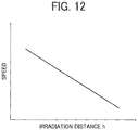
- the memory 32 previously stores information regarding relation between the irradiation distance h of the UV light and the speed of scanning the irradiator 400 (carriage 200) as illustrated in FIG. 12 .
- the movement controller 601 may reciprocally move (scan) the irradiator 400 (carriage 200) in the main scanning direction (X-axis direction) of the liquid surface (image) 102 at the speed corresponding to the irradiation distance h of the UV light.
- the speed of scanning the irradiator 400 (the carriage 200) is reduced with increase in the irradiation distance h of the UV light.
- the present embodiment can increase irradiation time for irradiating the liquid surface 102 with the UV light.
- the present embodiment can ensure the light quantity of the UV light sufficient for curing the UV-curable ink even when the irradiation distance of the UV light is large.
- the present embodiment of adjusting the speed of scanning the irradiator 400 is useful when the light quantity of the UV light of maximum output level is insufficient to cure the UV-curable ink.
- the irradiator 400 cannot irradiate all the area of the liquid surface 102 in the sub-scanning direction (Y-axis direction) with the UV light at once when the irradiator 400 (carriage 200) is at the maximum height of the irradiator 400 (carriage 200) that corresponds to the maximum irradiation distance of the irradiator 400.
- the movement controller 601 preferably scans the irradiator 400 (carriage 200) in the main scanning direction (X-axis direction) of the liquid surface 102 to irradiate an end of the liquid surface 102 in the sub-scanning direction (Y-axis direction) with the UV light having large light quantity.
- the sub-scanning direction (Y-axis direction) is direction along the width D of the liquid surface 102.
- the conveyor 100 previously moves the substrate 101 in the sub-scanning direction (Y-axis direction) so that one end (left end in FIG. 13 ) of the normal irradiation width L1 of the UV light of the irradiator 400 in the sub-scanning direction is substantially aligned with one end (left end in FIG. 13 ) of the width D of the liquid surface 102 in the sub-scanning direction (The left end in FIG. 13 ).
- the movement controller 601 moves the irradiator 400 (carriage 200) to the height where the light quantity of the UV light in the portion of Lr/2 protruding from the normal irradiation width L1 in the irradiation width Lh in the sub-scanning direction (Y-axis direction) is below the sufficient output level for sufficiently curing the liquid surface 102.
- the present embodiment can prevent an occurrence of uncured portion or insufficiently cured portion in the liquid surface 102 on both ends of the liquid surface 102 in the sub-scanning direction by irradiating the UV light to the liquid surface 102 with the irradiator 400 while scanning the irradiator 400 (carriage 200) in the main scanning direction (X-axis direction). That is, it is possible to reduce the number of times of additional irradiation for completely curing an insufficiently cured portion from twice to once.
- the portion Lr/2 protruding from the normal irradiation width L1 is irradiated with UV light having a light quantity below the sufficient output level to cure the liquid surface 102.
- a degree of curing shrinkage created in this portion is small, and the degree of wrinkles 103 created at a boundary between the cured portion and the uncured portion is also small.
- the conveyor 100 previously moves the substrate 101 in the sub-scanning direction (Y-axis direction) so that the irradiator 400 can irradiates a portion of the liquid surface 102 (right end portion of the liquid surface 102 in FIGS. 13 and 14 ) to which the UV light of the portion Lr/2 protruding from the normal irradiation width L1 is irradiated in FIG. 13 .
- the irradiator 400 irradiates the right end portion of the liquid surface 102 with the UV light within the normal irradiation width L1 as illustrated in FIG. 14 .
- the height adjuster 207 moves the irradiator 400 (carriage 200) at the height corresponding to the irradiation distance suitable for discharging the UV-curable ink by the heads 300 such as 1 mm.
- the scanner 206 reciprocally moves (scans) the irradiator 400 (the carriage 200) in the main scanning direction (X-axis direction) and irradiates the liquid surface 102 with the UV light by the irradiator 400.
- the present embodiment can cure and hardens all the surface of the liquid surface 102 while preventing deterioration of the quality of the liquid surface 102 (image) even when the irradiator 400 cannot irradiate the liquid surface 102 at once with the UV light.
- Fig. 15 is a flowchart that illustrates an example of a curing process according to the present disclosure.
- a height of the irradiator 400 (carriage 200) at a time of starting the curing process is at a height (1 mm, for example) suitable for discharge the UV-curable ink by the heads 300 as described above.
- a height of the irradiator 400 (carriage 200) is not limited to this example.
- the movement controller 601 checks whether the width D of the liquid surface 102 in the sub-scanning direction is equal to or smaller than the normal irradiation width L1 of the UV light in the sub-scanning direction (D ⁇ L1) (S101).
- the movement controller 601 controls the conveyor 100 to move the substrate 101 in the sub-scanning direction so that a center C1 of the liquid surface 102 in the direction of width D of the liquid surface 102 in the sub-scanning direction is substantially aligned with a center C2 of the irradiator 400 (irradiation width L1) in the sub-scanning direction (step S103).
- the irradiation controller 603 controls the irradiator 400 to irradiate the liquid surface 102 with the UV light to cure and harden the liquid surface 102 (step S105).
- the movement controller 601 determines whether the width D of the liquid surface 102 in the sub-scanning direction is equal to or less than the maximum irradiation width Lmax of the UV light in the sub-scanning direction (L1 ⁇ D ⁇ Lmax) (step S107).
- the movement controller 601 moves the irradiator 400 (carriage 200) to the height corresponding to the irradiation distance h at which the irradiation width Lh of the UV light in the sub-scanning direction is equal to or larger than the width D of the liquid surface 102 in the sub-scanning direction (Lh ⁇ D) (step S109).
- the movement controller 601 controls the conveyor 100 to move the substrate 101 in the sub-scanning direction so that a center C1 the liquid surface 102 (center of width D) in the sub-scanning direction is substantially aligned with a center C2 of the irradiator 400 (center of irradiation width L1) in the sub-scanning direction (step S111).
- the irradiation controller 603 controls the irradiator 400 to irradiate the liquid surface 102 with the UV light to cure and harden the liquid surface 102 (step S113).
- the movement controller 601 controls the conveyor 100 to move the substrate 101 in the sub-scanning direction so that one end of the normal irradiation width L1 of the UV light of the irradiator 400 in the sub-scanning direction is substantially aligned with one end of the width D of the liquid surface 102 in the sub-scanning direction (See FIG. 13 ).
- the movement controller 601 further raise the irradiator 400 (carriage 200) to the height corresponding to the irradiation distance h at which the light quantity of the portion Lr/2 protruding from the normal irradiation width L1 in the irradiation width Lh in the sub-scanning direction is less than the sufficient output level for curing the liquid surface 102.
- the irradiation controller 603 controls the irradiator 400 to irradiate the liquid surface 102 with the UV light to cure and harden the liquid surface 102.
- the movement controller controls the conveyor 100 to move the substrate 101 for the normal irradiation width L1 in the sub-scanning direction.
- the irradiation controller 603 controls the irradiator 400 to irradiate the liquid surface 102 with the UV light to cure and harden the liquid surface 102.
- the controller 3 repeats the above described process of moving the substrate 101 and the irradiator 400 to irradiate and cure all of the liquid surface 102 (step S117).
- the present embodiment can prevent forming of coating film having appearance defects on the liquid surface (image) 102.
- the present embodiment can prevent degradation of the quality of the liquid surface (image) 102.
- FIG. 16 illustrates the case in which the method according to the present disclosure is adopted. As can be seen from FIG. 16 , no wrinkles 103 are observed in the coating film and degradation of the quality of the liquid surface 102 is prevented.
- FIG. 17 illustrates the case in which the ordinal method is adopted. As can be seen from FIG. 17 , wrinkles 103 on the border are observed in the coating film, and the degradation of the quality of the liquid surface 102 is created.
- the illuminance of the UV light is adjusted according to the irradiation distance h of the UV light.
- any type of the UV irradiation lamp may be used for constituting the irradiator 400 in the present embodiment.
- the present embodiment can also adopt a high output lamp such as a metal halide that is difficult to adjust the output level of the UV irradiation lamp (irradiator 400).
- a high output lamp such as a metal halide that is difficult to adjust the output level of the UV irradiation lamp (irradiator 400).
- the method of changing the irradiation distance of the UV light of the irradiator 400 is not limited to the method described above.
- the irradiation distance of the UV light of the irradiator 400 may be changed by fixing the height of the irradiator 400 (carriage 200) and moving the substrate 101 in the Z-axis direction (height direction).
- the irradiation distance of the UV light of the irradiator 400 may be changed by moving both the carriage 200 and the substrate 101 in the Z-axis direction (height direction).
- a computer program product including a program executed by the liquid discharge apparatus 1 according to the above described embodiments and variations is provided to the user by being recorded on computer-readable recording media (non-transitory computer-readable medium) such as a compact disc read-only memory (CD-ROM), a compact disc-recordable (CD-R), a memory card, a digital versatile disc (DVD), a flexible disk (FD), in the file form installable into or executable by the PC 2 or by the controller 3 of the liquid discharge apparatus 1.
- computer-readable recording media non-transitory computer-readable medium
- CD-ROM compact disc read-only memory
- CD-R compact disc-recordable
- FD digital versatile disc
- FD flexible disk
- the program executed by the liquid discharge apparatus 1 in the above described embodiments and variations may be provided by being stored on a computer connected to a network such as an internet, and the program may be provided to the user via the network so that the user may download the program via the network.
- the program executed by the liquid discharge apparatus 1 according to the above described embodiments and variations or by the PC 2 may be provided or distributed via a network such as the Internet. Further, a program executed by the liquid discharge apparatus 1 according to the above described embodiments and variations or by the PC 2 may be a built-in read-only memory (ROM), etc.
- ROM read-only memory
- a program executed by the liquid discharge apparatus 1 according to the above described embodiments and variations or by the PC 2 has a modular architecture to realize each of the above described parts on the PC 2 or the controller 3.
- the CPU 33 reads out the program from the read-only memory (ROM) onto the random access memory (RAM) in the memory 32 and executes to realize each of the above described functional parts on the PC 2 or the controller 3.
- discharged liquid is not limited to a particular liquid as long as the liquid has a viscosity or surface tension to be discharged from a head.
- the viscosity of the liquid is not greater than 30 mPa ⁇ s under ordinary temperature and ordinary pressure or by heating or cooling.
- liquid examples include a solution, a suspension, or an emulsion including, for example, a solvent, such as water or an organic solvent, a colorant, such as dye or pigment, a functional material, such as a polymerizable compound, a resin, or a surfactant, a biocompatible material, such as DNA, amino acid, protein, or calcium, and an edible material, such as a natural colorant.
- a solvent such as water or an organic solvent
- a colorant such as dye or pigment
- a functional material such as a polymerizable compound, a resin, or a surfactant
- biocompatible material such as DNA, amino acid, protein, or calcium
- an edible material such as a natural colorant.
- Such a solution, a suspension, or an emulsion can be used for, e.g., inkjet ink, surface treatment solution, a liquid for forming components of electronic element or light-emitting element or a resist pattern of electronic circuit, or a material solution for three-dimensional fabrication.
- Examples of an energy source for generating energy to discharge liquid include a piezoelectric actuator (a laminated piezoelectric element or a thin-film piezoelectric element), a thermal actuator that employs a thermoelectric conversion element, such as a heating resistor (element), and an electrostatic actuator including a diaphragm and opposed electrodes.
- a piezoelectric actuator a laminated piezoelectric element or a thin-film piezoelectric element
- a thermal actuator that employs a thermoelectric conversion element, such as a heating resistor (element)
- an electrostatic actuator including a diaphragm and opposed electrodes.
- a liquid discharge device is an integrated unit including the head and a functional part(s) or unit(s), and is an assembly of parts relating to liquid discharge.
- the liquid discharge device may be a combination of the head with at least one of a head tank, a carriage, a supply unit, a maintenance unit, and a drive unit.
- the terms "integrated” or “united” mean fixing the head and the functional parts (or mechanism) to each other by fastening, screwing, binding, or engaging and holding one of the head and the functional parts movably relative to the other.
- the head may be detachably attached to the functional part(s) or unit(s) each other.
- the head and a head tank may be integrated into a single unit as the liquid discharge device.
- the head and the head tank may be connected each other via, e.g., a tube to integrally form the liquid discharge device.
- a unit including a filter may further be added to a portion between the head tank and the head of the liquid discharge device.
- the liquid discharge device may be an integrated unit in which a head is integrated with a carriage.
- the liquid discharge device may be the head movably held by a guide that forms part of a drive unit, so that the head and the drive unit are integrated as a single unit.
- the liquid discharge device may include the head, the carriage, and the drive unit that are integrated as a single unit.
- a cap that forms part of a maintenance unit is secured to the carriage mounting the head so that the head, the carriage, and the maintenance unit are integrated as a single unit to form the liquid discharge device.
- the liquid discharge device may include tubes connected to the head mounted on the head tank or the channel member so that the head and the supply unit are integrated as a single unit. Liquid is supplied from a liquid reservoir source such as liquid cartridge to the head through the tube.
- the drive unit may be a guide only.
- the supply unit may be a tube(s) only or a mount part (loading unit) only.
- liquid discharge apparatus also represents an apparatus including the head or the liquid discharge device to discharge liquid by driving the head.
- the liquid discharge apparatus may be, for example, an apparatus capable of discharging liquid onto a material to which liquid can adhere or an apparatus to discharge liquid toward gas or into liquid.
- the “liquid discharge apparatus” may include devices to feed, convey, and eject the material on which liquid can adhere.
- the liquid discharge apparatus may further include a pretreatment apparatus to coat a treatment liquid onto the material, and a post-treatment apparatus to coat a treatment liquid onto the material, on which the liquid has been discharged.
- the “liquid discharge apparatus” may be, for example, an image forming apparatus to form an image on a sheet by discharging ink, or a three-dimensional fabricating apparatus to discharge a fabrication liquid onto a powder layer in which powder material is formed in layers, so as to form a three-dimensional fabrication object.
- the liquid discharge apparatus is not limited to such an apparatus to form and visualize meaningful images, such as letters or figures, with discharged liquid.
- the liquid discharge apparatus may be an apparatus to form meaningless images, such as meaningless patterns, or fabricate three-dimensional images.
- material on which liquid can be adhered represents a material on which liquid is at least temporarily adhered, a material on which liquid is adhered and fixed, or a material into which li quid is adhered to permeate.
- Examples of the "medium on which liquid can be adhered” include recording media, such as paper sheet, recording paper, recording sheet of paper, film, and cloth, electronic component, such as electronic substrate and piezoelectric element, and media, such as powder layer, organ model, and testing cell.
- the "medium on which liquid can be adhered” includes any medium on which liquid is adhered, unless particularly limited.
- the material on which liquid can be adhered examples include any materials on which liquid can be adhered even temporarily, such as paper, thread, fiber, fabric, leather, metal, plastic, glass, wood, and ceramic.
- the liquid discharge apparatus may be an apparatus to relatively move a head and a medium on which liquid can be adhered.
- the liquid discharge apparatus is not limited to such an apparatus.
- the liquid discharge apparatus may be a serial head apparatus that moves the head or a line head apparatus that does not move the head.
- the liquid discharge apparatus further include a treatment liquid coating apparatus to discharge a treatment liquid onto a sheet surface to coat the sheet surface with the treatment liquid to reform the sheet surface and an injection granulation apparatus to eject a composition liquid including a raw material dispersed in a solution from a nozzle to mold particles of the raw material.
- image formation means “image formation”, “recording”, “printing”, “image printing”, and “fabricating” used herein may be used synonymously with each other.
Landscapes
- Health & Medical Sciences (AREA)
- General Health & Medical Sciences (AREA)
- Toxicology (AREA)
- Physics & Mathematics (AREA)
- Electromagnetism (AREA)
- Ink Jet (AREA)
Abstract
Description
- Aspects of the present disclosure relate to a liquid discharge apparatus, a liquid curing method, and a computer program product.
- Conventionally, a technique for forming an image by using an active energy rays-curable liquid such as a UV- (ultraviolet-) curable ink or the like is known. In such a technique, UV-curable ink is discharged onto a medium and irradiated and cured with UV light to form an image.
- In such a technique, it is also possible to change the texture of the image formed on the medium by changing timing of curing of the UV-curable ink. For example, a method of immediately curing a UV-curable ink discharged onto a medium can form an image with a matte feel since the discharged UV-curable ink is cured before becoming smooth. Further, a method of curing the UV-curable ink after a certain period of time can form glossy images since the discharged UV-curable ink is cured only after UV-curable ink has become smooth.
- In terms of productivity, the method of curing the UV-curable ink after a certain period of time is generally performed by discharging the UV-curable ink over multiple scans and collectively curing the UV-curable ink instead of curing the UV-curable ink every time the UV-curable ink is discharged in a single scan.
- Therefore, an image formed on the medium by discharging the UV-curable ink for a plurality of scans that is larger than the irradiation width of UV light requires multiple UV irradiations because a single UV irradiation cannot cure the entire
liquid surface 102. - However, when UV irradiation process is performed multiple times, a cured (hardened) portion cured by the UV irradiation process and an uncured (unhardened) portion not irradiated and not cured by the UV irradiation process are created on the
liquid surface 102 for each time UV irradiation is performed. As a result, wrinkles are created at a boundary between the cured portion and the uncured portion because curing shrinkage of the UV-curable ink occurs in the cured portion. Thus, the quality of the image deteriorates. - In order to solve such a problems, for example,
JP-2015-53057-A - However, degradation of image quality may not be prevented by the technique disclosed in
JP-2015-53057-A - Therefore, the present disclosure describes a liquid discharge apparatus, a liquid curing method, and a computer program product capable of preventing the degradation of image quality irrespective of the degree of the curing shrinkage.
- In an aspect of this disclosure, a novel liquid discharge apparatus (1) includes a liquid discharge head (300) to discharge liquid to a medium (101) to form liquid surface (102) on the medium (101), an irradiator (400) to irradiate the liquid surface (102) with active energy rays, a carriage (200) mounting the liquid discharge head (300) and the irradiator (400), a scanner (206) to scan the carriage in a main scanning direction, a height adjuster (207) to adjust an irradiation distance between the irradiator (400) and the liquid surface (102) by relatively moving the carriage (200) and the medium (101), a conveyor (100) to move the medium (101) and the carriage (200) relatively in a sub-scanning direction perpendicular to the main scanning direction, and control circuitry (31) to irradiate the liquid surface with the active energy rays by the irradiator (400) while scanning the carriage (200) in the main scanning direction. The height adjuster (207) adjusts the irradiation distance at a first distance in response to a maximum width of the liquid surface (102) in the sub-scanning direction being a first width and adjusts the irradiation distance at a second distance larger than the first distance in response to the maximum width of the liquid surface (102) in the sub-scanning direction being a second width larger than the first width. The control circuitry (31) controls the irradiator (400) to irradiate the liquid surface (102) with the active energy rays while maintaining the irradiation distance at the first distance or the second distance determined by the maximum width by the height adjuster (207).
- In another aspect of this disclosure, a novel liquid curing method includes discharging liquid to a medium to form liquid surface (102) on the medium (101), irradiating the liquid surface (102) with active energy rays using an irradiator (400), adjusting an irradiation distance between the irradiator (400) and the liquid surface (102) by relatively move the irradiator (400) with the medium (101), scanning the irradiator (400) in a main scanning direction, moving the medium (101) and the irradiator (400) relatively in a sub-scanning direction perpendicular to the main scanning direction, and controlling irradiation of the liquid surface (102) with the active energy rays while scanning the irradiator (400) in the main scanning direction. The adjusting adjusts the irradiation distance at a first distance in response to a maximum width of the liquid surface (102) in the sub-scanning direction being a first width and adjusts the irradiation distance at a second distance larger than the first distance in response to the maximum width of the liquid surface (102) in the sub-scanning direction being a second width larger than the first width, and the controlling irradiates the liquid surface (102) with the active energy rays while maintaining the irradiation distance at the first distance or the second distance determined by the maximum width.
- In still another aspect of this disclosure, a novel computer program product includes a computer-readable medium containing an information processing program that causes a computer (2, 3) in a device to perform the method as described above.
- The present embodiment has an effect of preventing the degradation of image quality irrespective of the degree of the curing shrinkage.
-
-
FIG. 1 is a block diagram of an example of a hardware structure of a liquid discharge apparatus according to the present disclosure; -
FIG. 2 is a schematic front view of the liquid discharge apparatus according to the present disclosure; -
FIG. 3 is a schematic plan view of the liquid discharge apparatus according to the present disclosure; -
FIG. 4 is a schematic plan view and cross-sectional view of the liquid discharge apparatus illustrating an example of an irradiation operation in the present disclosure; -
FIG. 5 is a schematic plan view and cross-sectional view of the liquid discharge apparatus illustrating an example of a conventional irradiation operation; -
FIG. 6 is a block diagram of a functional configuration of the liquid discharge apparatus (controller) according to the present disclosure; -
FIG. 7 is an explanatory cross-sectional view of an example of the relation between an irradiation distance of UV light of an irradiator and the irradiation width of the irradiator according to the present embodiment; -
FIG. 8 is a schematic plan view and cross-sectional view of the liquid discharge apparatus illustrating an example of an irradiation operation in the present disclosure; -
FIG. 9 is a schematic plan view and cross-sectional view of the liquid discharge apparatus illustrating another example of the irradiation operation in the present disclosure; -
FIG. 10 is a schematic cross-sectional view of the liquid discharge apparatus illustrating an example of the irradiation operation in the present disclosure; -
FIG. 11 is a graph illustrating an example of an output level of the UV light according to an embodiment of the present disclosure; -
FIG. 12 is a graph illustrating an example of a relation between the irradiation distance of the UV light and a speed of moving the irradiator (carriage) according to the embodiment of the present disclosure. -
FIG. 13 is a schematic plan view and cross-sectional view of the liquid discharge, apparatus illustrating still another example of the irradiation operation in the present disclosure; -
FIG. 14 is a schematic plan view and cross-sectional view of the liquid discharge, apparatus illustrating still another example of the irradiation operation in the present disclosure; -
FIG. 15 is a flowchart that illustrates an example of a curing process according to the present disclosure; -
FIG. 16 illustrates an example of a result of a curing process according to the present disclosure; and -
FIG. 17 illustrates an example of a result of a conventional curing process. - A liquid discharge apparatus according to an embodiment of the present disclosure is described with reference to the accompanying drawings.
- The liquid discharge apparatus includes a liquid discharge head that discharges liquid from nozzles, a carriage to mount the liquid discharge head to move horizontally and vertically, and a maintenance unit to maintain the liquid discharge head. Hereinafter, a liquid discharge apparatus, a method for curing liquid, and a computer program product according to an embodiments of the present disclosure will be described referring to accompanying drawings. In following description, an inkjet apparatus using a UV (ultraviolet) curable ink will be described as an example of a liquid discharge apparatus. However, note that the liquid discharge apparatus according to the present embodiment is not limited to an inkjet apparatus of UV (ultraviolet) curable ink.
-
FIG. 1 is a block diagram of a hardware configuration of aliquid discharge apparatus 1 according to the present disclosure.FIG. 2 is a schematic front view of theliquid discharge apparatus 1 of the present embodiment.FIG. 3 is a top view of theliquid discharge apparatus 1 of the present embodiment. - As illustrated in
FIG. 1 , theliquid discharge apparatus 1 according to the present embodiment includes controller (control circuitry) 3, asensor group 4, aconveyor 100, acarriage 200,liquid discharge heads 300, anirradiator 400, and amaintenance unit 500. Theliquid discharge heads 300 are an example of a liquid discharge device. Hereinafter, the "liquid discharge head" is simply referred to as "head". - Further, the
controller 3 includesunit control circuitry 31, a memory 32, a CPU (Central Processing Unit) 33, and an I/F (Interface) 34. As illustrated by a broken line inFIG. 1 , a curing device may be an apparatus including at least thecontroller 3 and theirradiator 400. - The I / F 34 is an interface for connecting the
liquid discharge apparatus 1 to an external PC (Personal Computer) 2. A form of connection between theliquid discharge apparatus 1 and thePC 2 may be any type. For example, theliquid discharge apparatus 1 and the PC 2 may be connected via a network or directly connected by a communication cable. - Examples of the
sensor group 4 include various sensors provided in theliquid discharge apparatus 1 such as theheight sensor 41 illustrated inFIGS. 2 and3 . - The
CPU 33 uses the memory 32 as a work area to control the operation of each unit of theliquid discharge apparatus 1 via theunit control circuitry 31. Specifically, theCPU 33 controls the operation of each unit based on print data received from thePC 2 and the data detected by thesensor group 4. TheCPU 33 forms an image on asubstrate 101. The "image" formed on asubstrate 101 is also referred to as a "liquid surface 102". Thesubstrate 101 is an example of a medium onto which the liquid is discharged. Thus, the "substrate" is also referred to as a "medium". - Note that a printer driver is installed in the
PC 2. The printer driver generates print data from image data. The print data is transmitted to theliquid discharge apparatus 1. The print data includes command data and pixel data. The command data is used for operating theconveyor 100 of theliquid discharge apparatus 1, for example. The pixel data relates to the image (liquid surface 102) formed on thesubstrate 101. The pixel data is composed of 2-bit data for each pixel and is represented by four gradations. - The
conveyor 100 includes astage 130 and asuction mechanism 120. Thesuction mechanism 120 includesfans 110 andsuction holes 100a formed in thestage 130. Thesuction mechanism 120 drives thefans 110 to vacuum thesubstrate 101 to thestage 130 through thesuction holes 100a. Thesubstrate 101 is thus temporary fixed to thestage 130 of theconveyor 100 by thesuction mechanism 120. - The
suction mechanism 120 may also attract thesubstrate 101 to thestage 130 with electrostatic force. Thestage 130 is controlled to move in a Y-axis direction (sub-scanning direction) based on a drive signal from the CPU 33 (unit control circuitry 31). As illustrated inFIG. 3 , theconveyor 100 includes aconveyance controller 210, aroller 105, and amotor 104. Theconveyance controller 210 drives themotor 104 to rotate theroller 105 to move thesubstrate 101 in the sub-scanning direction (Y-axis direction). - The
conveyor 100 may move thecarriage 200 in the sub-scanning direction (Y-axis direction) instead of moving thesubstrate 101. That is, theconveyor 100 relatively moves thesubstrate 101 and thecarriage 200 in the sub-scanning direction (Y-axis direction). - For example, as illustrated in right side in
FIG. 3 , theconveyor 100 includes aside plate 407b that supports twoguides 201 that guide thecarriage 200 in the main scanning direction (X-axis direction), a base 406 to support theside plate 407b, abelt 404 that is fixed to thebase 406 and wound around adrive pulley 403 and a drivenpulley 402, amotor 405 that drives and rotates thedrive pulley 403, and aconveyance controller 210. - Similarly, as illustrated in left side in
FIG. 3 , theconveyor 100 includes aside plate 407a that supports twoguides 201 that guide thecarriage 200 in the main scanning direction (X-axis direction), a base 408 to slidably support theside plate 407a, agroove 409 formed on the base 408 to guide theside plate 407a to move in the sub-scanning direction (Y-axis direction). - The
conveyance controller 210 of theconveyor 100 drives themotor 405 to rotate thedrive pulley 403 to move thebelt 404 in the sub-scanning direction (Y-axis direction). Thecarriage 200 moves in the Y-axis direction (sub-scanning direction) by moving thebase 406 and theside plate 407b in the Y-axis direction (sub-scanning direction) with movement of thebelt 404. - The
side plate 407a moves in the sub-scanning direction along thegroove 409 of the base 408 as the base 406 moves in the sub-scanning direction. Theheads 300 includesheads - The UV-curable ink is an example of a liquid curable by active energy rays. The
heads carriage 200. Each heads 300K, 300C, 300M, 300Y, 300CL, and 300W has a piezoelectric element, a liquid chamber, and a nozzle. The CPU 33 (unit control circuitry 31) applies drive signals to the piezoelectric elements to cause the piezoelectric elements to deform toward the nozzle so that the liquid in the liquid chamber is discharged from the nozzle. Thus, the UV-curable ink is discharged onto thesubstrate 101. Thus, theliquid surface 102 is formed on thesubstrate 101. - As UV-curable ink suitable for the present embodiment, ink containing a methacrylate monomer may be listed as an example. Although the methacrylate monomer has an advantage of comparatively weak skin sensibility, the methacrylate monomer has a characteristic that degree of cure shrinkage of the methacrylate monomer is larger than the cure shrinkage of ordinary inks.
- The
irradiator 400 is provided on a side surface of thecarriage 200 in the X-axis direction. Theirradiator 400 irradiates UV light (an example of active energy rays) to theliquid surface 102 based on a driving signal from the CPU 33 (unit control circuitry 31). Theirradiator 400 is mainly constituted by a UV irradiation lamp that irradiates UV light. - The CPU 33 (unit control circuitry 31) controls the
carriage 200 to move in a Z-axis direction (height direction) and a main scanning direction (X-axis direction) by drive signals generated by theCPU 33. Thus, thecarriage 200 scans and moves in the main scanning direction (X-axis direction) along theguide 201. Thescanner 206 includes a drivingpulley 203, a drivenpulley 204, a drivingbelt 202, and amotor 205. Thecarriage 200 is fixed to the drivingbelt 202 wound around the drivingpulley 203 and the drivenpulley 204. By driving the drivingbelt 202 with themotor 205, thecarriage 200 moves to the right and left in the main scanning direction (X-axis direction). - The
guide 201 is supported by theside plate 211A and the 211B of the apparatus body. Theheight adjuster 207 has amotor 209 and aslider 208. Theheight adjuster 207 drives themotor 209 to vertically move theslider 208 to move theguide 201 vertically. As theguide 201 moves vertically, thecarriage 200 moves vertically, and thus the height of thecarriage 200 with respect to thesubstrate 101 can be adjusted. - Next, image formation using the
liquid discharge apparatus 1 is described. - First, the
conveyor 100 moves thesubstrate 101 to an initial position in the Y-axis direction (sub-scanning direction) based on the drive signal transmitted from the CPU 33 (unit control circuitry 31) to form the image (liquid surface 102) on thesubstrate 101. - Next, the
height adjuster 207 adjusts a height of thecarriage 200 by moving thecarriage 200 in the Z-axis direction (height direction) based on the drive signal transmitted from the CPU 33 (unit control circuitry 31). - The
height adjuster 207 moves the carriage to a height suitable for discharging UV-curable ink by theheads 300. For example, the height at which the gap between theheads 300 and thesubstrate 101 is 1 mm. The height of theheads 300 is detected by theheight sensor 41 so that the height of theheads 300 is controlled by theCPU 33. - The
carriage 200 reciprocally moves in the X-axis direction (main scanning direction) based on the driving signal transmitted from the CPU 33 (unit control circuitry 31). Theheads 300 discharges UV-curable ink based on the drive signal transmitted from the CPU 33 (unit control circuitry 31) during reciprocal movement of thecarriage 200. Thus, an image (liquid surface 102) is formed on thesubstrate 101 for one scan. - The
conveyor 100 moves thesubstrate 101 in the Y-axis direction (sub-scanning direction) for one scan based on the drive signal from the CPU 33 (unit control circuitry 31) after the image (liquid surface 102) is formed on thesubstrate 101 for one scan. - The operation of forming an image (liquid surface 102) for one scan and the operation of moving the
substrate 101 andcarriage 200 relatively in the Y-axis direction (sub-scanning direction) for one scan are alternatively performed until the formation of the image (liquid surface 102) is completed. - The
liquid discharge apparatus 1 waits for a certain period of time (also referred to as "leveling time") during which theliquid surface 102 of the UV-curable ink is leveled (smoothed) after the formation of the image (liquid surface 102) on thesubstrate 101 is completed. Then, theirradiator 400 irradiates UV light to theliquid surface 102. - The
irradiator 400 irradiates theliquid surface 102 with UV light to during scanning thecarriage 200 in the main scanning direction (X-axis direction) after moving thecarriage 200 at the height suitable for discharging the UV-curable ink by theheads 300. - As illustrated in
FIG. 4 , a width D of the liquid surface (image) 102 formed on thesubstrate 101 is larger than an irradiation width L1 of the UV light irradiated from theirradiator 400 in the sub-scanning direction (Y-axis direction) (D> L1). At this time, thecarriage 200 is at the height as described above, for example, the height at which the irradiation distance (gap) h between theheads 300 and theliquid surface 102 is 1 mm. The irradiation distance h is a height (distance) from the liquid surface 102 (irradiation surface) to theirradiator 400. - Thus, it is necessary to irradiate the
liquid surface 102 multiple times with the UV light to irradiate all theliquid surface 102 when theirradiator 400 irradiates theliquid surface 102 from the above described height of 1 mm. In other words, thecarriage 200 has to move reciprocally in the main scanning direction (X-axis direction) every time the relative positions of theirradiator 400 and thesubstrate 101 in the sub-scanning direction are changed by relatively moving thecarriage 200 and thesubstrate 101 in the sub-scanning direction (Y-axis direction). However, as illustrated inFIG. 5 , a cured portion (hardened portion) cured by UV irradiation with the UV light and an uncured portion (unhardened portion) that is not irradiated with the UV light and not cured by UV irradiation are created on theliquid surface 102 every time the UV irradiation process is performed. As a result, curing shrinkage of the UV-curable ink occurs in the cured portion, and curing shrinkage of the UV-curable ink does not occur in the uncured portion. Thus,wrinkles 103 are formed at a boundary between the cured portion and the uncured portion, forming a coating film with poor appearance. Thus, the quality of the liquid surface (image) 102 deteriorates. - Note that the coating film may be obtained by curing the UV-curable ink of colors (K, C, M, Y, and W) or UV-curable ink (UV) itself. In addition, the coating film may be obtained by curing clear (CL) UV-curable ink applied on top of curable ink of colors (K, C, M, Y, and W).
- In order to avoid such a problem, in the present embodiment, a height of the
irradiator 400 for performing an irradiation of the UV light is adjusted. -
FIG. 6 is a block diagram of a functional configuration of the liquid discharge apparatus 1 (controller 3) according to the present disclosure. - As illustrated in
FIG. 6 , thecontroller 3 of theliquid discharge apparatus 1 includes amovement controller 601 and an irradiation controller 603. Themovement controller 601 controls thescanner 206, theheight adjuster 207, and theconveyance controller 210. The irradiation controller 603 controls the UV irradiation process of theirradiator 400. - The
movement controller 601 moves the irradiator 400 (carriage 200) to a height at which the irradiation distance h between the irradiator 400 and theliquid surface 102 on thesubstrate 101 is equal to or larger than a distance according the width D of theliquid surface 102. - Then, the
movement controller 601 moves the irradiator 400 (carriage 200) in the main scanning direction (X-axis direction) perpendicular to a direction of the width D of theliquid surface 102. The direction of the width D is along the sub-scanning direction (Y-axis direction). - The
movement controller 601 controls thescanner 206 to move thecarriage 200 in the main scanning direction (X-axis direction) and controls theheight adjuster 207 to adjust the position in a height direction (Z-axis direction) of thecarriage 200 and controls theconveyance controller 210 to convey thesubstrate 101 of theconveyor 100 in the sub-scanning direction (Y-axis direction). - The distance according to the width D of the
liquid surface 102 is a distance at which theirradiator 400 is capable of irradiating theliquid surface 102 at once by the UV light (active energy rays) in the sub-scanning direction (Y-axis direction). - In other words, the irradiation distance is a distance in which the active energy rays (UV light) irradiated from the
irradiator 400 covers a maximum width Dmax of theliquid surface 102 in the sub-scanning direction (Y-axis direction) . - While the irradiator 400 (carriage 200) moves and scans in the main scanning direction (X-axis direction) perpendicular to the direction of the width D (sub-scanning direction, Y-axis direction) of the
liquid surface 102, the irradiation controller 603 controls theirradiator 400 to irradiate and cure theliquid surface 102 with the UV light (active energy rays). -
FIG. 7 is a cross-sectional view of theirradiator 400 and theliquid surface 102 that explains an example of a relation between the irradiation distance of the UV light of theirradiator 400 and an irradiation width L of the present disclosure. The irradiation distance h is the gap (distance) between the irradiator 400 and theliquid surface 102. - As illustrated in
FIG. 7 , when the irradiation distance h of the UV light is 1 mm, the irradiation width L of the UV light in the sub-scanning direction is L1. As described above, the irradiation distance h = 1 mm of the UV light is used when theirradiator 400 irradiates the UV light from the height suitable for discharging the UV-curable ink by theheads 300. As the irradiation distance h of UV light increases, the irradiation width (irradiation range) L of the UV light in the sub-scanning direction (Y-axis direction) also increases. - Therefore, as illustrated in
FIG. 8 , themovement controller 601 controls theheight adjuster 207 to move the irradiator 400 (carriage 200) to the irradiation distance h at which the irradiation width Lh of the UV light becomes equal to or larger than the width D (Lh ≥ D) of theliquid surface 102 in the sub-scanning direction (Y-axis direction). - Here, the irradiation distance h is a distance from the
irradiator 400 to theliquid surface 102 formed on thesubstrate 101. Then, themovement controller 601 controls thescanner 206 to reciprocally scans the irradiator 400 (carriage 200) in the main scanning direction (X-axis direction) of theliquid surface 102. - In the present embodiment, the memory 32 previously stores information indicating the relation between the irradiation distance h of the UV light and the irradiation width L in the sub-scanning direction (Y-axis direction) of the UV light. The width D in the sub-scanning direction of the
liquid surface 102 can be specified from the recording data received from thePC 2. - Thus, the
movement controller 601 can specify the irradiation distance h of the UV light at which the irradiation width Lh of the UV light is equal to or larger than the width D of theliquid surface 102 in the sub-scanning direction (Y-axis direction). Further, themovement controller 601 can specify a height of the irradiator 400 (carriage 200) corresponding to the specified irradiation distance h. - The irradiation controller 603 controls the
irradiator 400 to irradiate and cure all theliquid surface 102 at once with the UV light while the irradiator 400 (carriage 200) reciprocally moves in the main scanning direction (X-axis direction) of theliquid surface 102. - Thus, the uncured portion is not formed on the
liquid surface 102, and formation of the coating film having poor appearance can be prevented. Thus, deterioration of the quality of the image (liquid surface 102) can be prevented. - The
height adjuster 207 adjusts the irradiation distance h at a first distance (1 mm) in response to a maximum width Dmax of theliquid surface 102 in the sub-scanning direction (Y-axis direction) being a first width and adjusts the irradiation distance h at a second distance (hmax) larger than the first distance (1 mm) in response to the maximum width Dmax of theliquid surface 102 in the sub-scanning direction (Y-axis direction) being a second width larger than the first width. - In a state where the irradiation distance h is maintained at the first distance or the second distance, the
controller 3 irradiates the UV light (active energy rays) from theirradiator 400 to theliquid surface 102. - As illustrated in
FIG. 8 , themovement controller 601 previously relatively moves thesubstrate 101 and theirradiator 400 in the sub-scanning direction (Y-axis direction) so that a center C1 of theliquid surface 102 and a center C2 of theirradiator 400 substantially aligned with each other in the sub-scanning direction (Y-axis direction). - As illustrated in
FIG. 7 , most of the light travels straight. Thus, among the irradiation width Lh of the UV light in the sub-scanning direction, an illuminance of the UV light on a portion Lr/2 (Lr = Lh - L1) protruding from a normal irradiation width L1 is lower than an illuminance within the normal irradiation width L1. Thus, light quantity of the UV light is different according to the position to be irradiated. - Particularly, the illuminance of the UV light on the portion Lr/2 protruding from the normal irradiation width L1 decrease toward outside an illuminance area of the UV light. If the center C1 of the
liquid surface 102 and the center C2 of theirradiator 400 are substantially aligned as described above, theirradiator 400 can irradiates theliquid surface 102 with the most uniform light quantity. Thus, aclean liquid surface 102 can be obtained and deterioration in quality of the liquid surface 102 (image) can be prevented. -
FIG. 9 illustrates an example of the irradiation operation in the present disclosure.FIG. 9 is different from the embodiment ofFIG. 8 in that a shape of theliquid surface 102 formed on thesubstrate 101 is T-shaped. - As illustrated n
FIG. 9 , in case where theliquid surface 102 has a complex shape such as an ellipse and T-shaped other than a rectangle, for example, a maximum width Dmax in the sub-scanning direction of theliquid surface 102 is used as the width D in the sub-scanning direction of theliquid surface 102. - Therefore, as illustrated in
FIG. 9 , themovement controller 601 controls theheight adjuster 207 to move the irradiator 400 (carriage 200) to the height corresponding to the irradiation distance h at which the irradiation width Lh of the UV light from theirradiator 400 in the sub-scanning direction is equal to or greater than the maximum width Dmax in the sub-scanning direction of the liquid surface 102 (Lh ≥ Dmax). - Then, the
movement controller 601 controls thescanner 206 to reciprocally scans the irradiator 400 (carriage 200) in the main scanning direction (X-axis direction) of theliquid surface 102. - As the irradiation distance of the UV light becomes longer, the light diffuses, and the illuminance decreases. As illustrated in
FIG. 10 , themovement controller 601 preferably controls theheight adjuster 207 to move thecarriage 200 to the height corresponding to the irradiation distance h at which the irradiation width Lh of the UV light from theirradiator 400 in the sub-scanning direction is equal to the width D of theliquid surface 102 in the sub-scanning direction (Lh=D). - Thus, there is no need to increase the illuminance of UV light more than necessary, and scattering of light can be suppressed, so that a
clean liquid surface 102 is obtained and the deterioration in quality of the image (liquid surface 102) can be prevented. - In addition, the irradiation controller 603 may control the
irradiator 400 to irradiate the UV light at an output level corresponding to the irradiation distance h of the UV light. As described above, the longer the irradiation distance of the UV light is, the lower the illuminance becomes. Therefore, depending on the irradiation distance h of the UV light, the light quantity of UV light may be insufficient to cure the UV-curable ink. - Therefore, the irradiation controller 603 may increase the output level of the UV light with an increase in the irradiation distance h when irradiating the UV light.
- For example, as illustrated in
FIG. 11 , three stages of the output levels of the UV light are prepared, such as small, medium, and large. - The irradiation controller 603 controls the
irradiator 400 to irradiate theliquid surface 102 with higher output level as the increase in the irradiation distance h between the irradiator 400 and theliquid surface 102. - Specifically, the above-described three levels of output levels are previously stored in the memory 32. The irradiation controller 603 adopts the output level among the three stages of the output levels that satisfies the condition of the lowest output level having a light quantity enough to cure the
liquid surface 102 with the UV light at the height corresponding to the irradiation distance h between the irradiator 400 and theliquid surface 102. - The light quantity enough to cure the
liquid surface 102 with the UV light is indicated inFIG. 11 as a "sufficient output level". - In this way, the
irradiator 400 irradiates the UV light at a higher output level with the increase in the irradiation distance h of the UV light. - Thus, the
irradiator 400 can irradiate theliquid surface 102 with the UV light having sufficient light quantity for curing the UV-curable ink even when the irradiation distance of the UV light is large. - Further, the
movement controller 601 may move the irradiator 400 (carriage 200) in the main scanning direction (X-axis direction) perpendicular to the width D direction of the liquid surface 102 (Y-axis direction or sub-scanning direction) at a speed corresponding to the irradiation distance h of the UV light. - As described above, the illuminance of the UV light decreases with increase in the irradiation distance of the UV light. Therefore, the light quantity of UV light may be insufficient to cure the UV-curable ink depending on the irradiation distance h of the UV light.
- Therefore, the
movement controller 601 reduce a speed of scanning the irradiator 400 (carriage 200) in the main scanning direction (X-axis direction) with increase in the irradiation distance h of the UV light. Themovement controller 601 then irradiates theliquid surface 102 while reciprocally moving (scanning) the irradiator 400 (carriage 200) with the reduced speed in the main scanning direction (X-axis direction). - For example, the memory 32 previously stores information regarding relation between the irradiation distance h of the UV light and the speed of scanning the irradiator 400 (carriage 200) as illustrated in
FIG. 12 . - The
movement controller 601 may reciprocally move (scan) the irradiator 400 (carriage 200) in the main scanning direction (X-axis direction) of the liquid surface (image) 102 at the speed corresponding to the irradiation distance h of the UV light. Thus, the speed of scanning the irradiator 400 (the carriage 200) is reduced with increase in the irradiation distance h of the UV light. - Thus, the present embodiment can increase irradiation time for irradiating the
liquid surface 102 with the UV light. Thus, the present embodiment can ensure the light quantity of the UV light sufficient for curing the UV-curable ink even when the irradiation distance of the UV light is large. - Especially, the present embodiment of adjusting the speed of scanning the
irradiator 400 is useful when the light quantity of the UV light of maximum output level is insufficient to cure the UV-curable ink. - There may be a case in which the
irradiator 400 cannot irradiate all the area of theliquid surface 102 in the sub-scanning direction (Y-axis direction) with the UV light at once when the irradiator 400 (carriage 200) is at the maximum height of the irradiator 400 (carriage 200) that corresponds to the maximum irradiation distance of theirradiator 400. - Thus, the
movement controller 601 preferably scans the irradiator 400 (carriage 200) in the main scanning direction (X-axis direction) of theliquid surface 102 to irradiate an end of theliquid surface 102 in the sub-scanning direction (Y-axis direction) with the UV light having large light quantity. The sub-scanning direction (Y-axis direction) is direction along the width D of theliquid surface 102. - For example, as illustrated in
FIG. 13 , theconveyor 100 previously moves thesubstrate 101 in the sub-scanning direction (Y-axis direction) so that one end (left end inFIG. 13 ) of the normal irradiation width L1 of the UV light of theirradiator 400 in the sub-scanning direction is substantially aligned with one end (left end inFIG. 13 ) of the width D of theliquid surface 102 in the sub-scanning direction (The left end inFIG. 13 ). - Further, as illustrated in
FIG. 13 , themovement controller 601 moves the irradiator 400 (carriage 200) to the height where the light quantity of the UV light in the portion of Lr/2 protruding from the normal irradiation width L1 in the irradiation width Lh in the sub-scanning direction (Y-axis direction) is below the sufficient output level for sufficiently curing theliquid surface 102. - In this way, the present embodiment can prevent an occurrence of uncured portion or insufficiently cured portion in the
liquid surface 102 on both ends of theliquid surface 102 in the sub-scanning direction by irradiating the UV light to theliquid surface 102 with theirradiator 400 while scanning the irradiator 400 (carriage 200) in the main scanning direction (X-axis direction). That is, it is possible to reduce the number of times of additional irradiation for completely curing an insufficiently cured portion from twice to once. - Further, the portion Lr/2 protruding from the normal irradiation width L1 is irradiated with UV light having a light quantity below the sufficient output level to cure the
liquid surface 102. Thus, a degree of curing shrinkage created in this portion is small, and the degree ofwrinkles 103 created at a boundary between the cured portion and the uncured portion is also small. - As illustrated in
FIG. 14 , theconveyor 100 previously moves thesubstrate 101 in the sub-scanning direction (Y-axis direction) so that theirradiator 400 can irradiates a portion of the liquid surface 102 (right end portion of theliquid surface 102 inFIGS. 13 and14 ) to which the UV light of the portion Lr/2 protruding from the normal irradiation width L1 is irradiated inFIG. 13 . - At this time, the
irradiator 400 irradiates the right end portion of theliquid surface 102 with the UV light within the normal irradiation width L1 as illustrated inFIG. 14 . - The
height adjuster 207 moves the irradiator 400 (carriage 200) at the height corresponding to the irradiation distance suitable for discharging the UV-curable ink by theheads 300 such as 1 mm. - The
scanner 206 reciprocally moves (scans) the irradiator 400 (the carriage 200) in the main scanning direction (X-axis direction) and irradiates theliquid surface 102 with the UV light by theirradiator 400. - In this way, the present embodiment can cure and hardens all the surface of the
liquid surface 102 while preventing deterioration of the quality of the liquid surface 102 (image) even when theirradiator 400 cannot irradiate theliquid surface 102 at once with the UV light. -
Fig. 15 is a flowchart that illustrates an example of a curing process according to the present disclosure. - In
FIG. 15 , an example is described in which a height of the irradiator 400 (carriage 200) at a time of starting the curing process is at a height (1 mm, for example) suitable for discharge the UV-curable ink by theheads 300 as described above. However, a height of the irradiator 400 (carriage 200) is not limited to this example. - First, the
movement controller 601 checks whether the width D of theliquid surface 102 in the sub-scanning direction is equal to or smaller than the normal irradiation width L1 of the UV light in the sub-scanning direction (D ≤ L1) (S101). - If D ≤ L1 (Yes in step S101), the
movement controller 601 controls theconveyor 100 to move thesubstrate 101 in the sub-scanning direction so that a center C1 of theliquid surface 102 in the direction of width D of theliquid surface 102 in the sub-scanning direction is substantially aligned with a center C2 of the irradiator 400 (irradiation width L1) in the sub-scanning direction (step S103). - While the
scanner 206 of themovement controller 601 scans (reciprocally moves) the irradiator 400 (carriage 200) in the main scanning direction (X-axis direction), the irradiation controller 603 controls theirradiator 400 to irradiate theliquid surface 102 with the UV light to cure and harden the liquid surface 102 (step S105). - On the other hand, when a condition of D ≤ L1 is not satisfied (No in step S101), the
movement controller 601 determines whether the width D of theliquid surface 102 in the sub-scanning direction is equal to or less than the maximum irradiation width Lmax of the UV light in the sub-scanning direction (L1 < D ≤ Lmax) (step S107). - If the condition of L1 < D ≤ Lmax (Yes in step S107) is satisfied, the
movement controller 601 moves the irradiator 400 (carriage 200) to the height corresponding to the irradiation distance h at which the irradiation width Lh of the UV light in the sub-scanning direction is equal to or larger than the width D of theliquid surface 102 in the sub-scanning direction (Lh ≥ D) (step S109). - Next, the
movement controller 601 controls theconveyor 100 to move thesubstrate 101 in the sub-scanning direction so that a center C1 the liquid surface 102 (center of width D) in the sub-scanning direction is substantially aligned with a center C2 of the irradiator 400 (center of irradiation width L1) in the sub-scanning direction (step S111). - While the
scanner 206 of themovement controller 601 scans (reciprocally moves) the irradiator 400 (carriage 200) in the main scanning direction (X-axis direction), the irradiation controller 603 controls theirradiator 400 to irradiate theliquid surface 102 with the UV light to cure and harden the liquid surface 102 (step S113). - On the other hand, if the condition of L1 < D ≤ Lmax is not satisfied (No in step S107), the
movement controller 601 controls theconveyor 100 to move thesubstrate 101 in the sub-scanning direction so that one end of the normal irradiation width L1 of the UV light of theirradiator 400 in the sub-scanning direction is substantially aligned with one end of the width D of theliquid surface 102 in the sub-scanning direction (SeeFIG. 13 ). - The
movement controller 601 further raise the irradiator 400 (carriage 200) to the height corresponding to the irradiation distance h at which the light quantity of the portion Lr/2 protruding from the normal irradiation width L1 in the irradiation width Lh in the sub-scanning direction is less than the sufficient output level for curing theliquid surface 102. - While the
scanner 206 of themovement controller 601 scans (reciprocally moves) the irradiator 400 (carriage 200) in the main scanning direction (X-axis direction), the irradiation controller 603 controls theirradiator 400 to irradiate theliquid surface 102 with the UV light to cure and harden theliquid surface 102. The movement controller controls theconveyor 100 to move thesubstrate 101 for the normal irradiation width L1 in the sub-scanning direction. - Then, while the
scanner 206 of themovement controller 601 scans (reciprocally moves) the irradiator 400 (carriage 200) in the main scanning direction (X-axis direction), the irradiation controller 603 controls theirradiator 400 to irradiate theliquid surface 102 with the UV light to cure and harden theliquid surface 102. - The
controller 3 repeats the above described process of moving thesubstrate 101 and theirradiator 400 to irradiate and cure all of the liquid surface 102 (step S117). - As described above, according to the present embodiment, quality deterioration of a liquid surface (image) 102 can be suppressed irrespective of the degree of curing shrinkage. Specifically, the present embodiment can prevent forming of coating film having appearance defects on the liquid surface (image) 102.
- Thus, the present embodiment can prevent degradation of the quality of the liquid surface (image) 102.
-
FIG. 16 illustrates the case in which the method according to the present disclosure is adopted. As can be seen fromFIG. 16 , nowrinkles 103 are observed in the coating film and degradation of the quality of theliquid surface 102 is prevented. - On the other hand,
FIG. 17 illustrates the case in which the ordinal method is adopted. As can be seen fromFIG. 17 ,wrinkles 103 on the border are observed in the coating film, and the degradation of the quality of theliquid surface 102 is created. - Further, according to the present embodiment, the illuminance of the UV light is adjusted according to the irradiation distance h of the UV light. Thus, any type of the UV irradiation lamp may be used for constituting the
irradiator 400 in the present embodiment. - That is, not only the UV irradiation lamp of a Light Emitting Diode (LED) type capable of adjusting the output level of the UV irradiation lamp (irradiator 400), the present embodiment can also adopt a high output lamp such as a metal halide that is difficult to adjust the output level of the UV irradiation lamp (irradiator 400).
- In the above described embodiments, an example of changing the irradiation distance of the UV light of the
irradiator 400 by moving the irradiator 400 (carriage 200) in the Z-axis direction (height direction) has been described. - However, the method of changing the irradiation distance of the UV light of the
irradiator 400 is not limited to the method described above. - For example, the irradiation distance of the UV light of the
irradiator 400 may be changed by fixing the height of the irradiator 400 (carriage 200) and moving thesubstrate 101 in the Z-axis direction (height direction). - Further, the irradiation distance of the UV light of the
irradiator 400 may be changed by moving both thecarriage 200 and thesubstrate 101 in the Z-axis direction (height direction). - A computer program product including a program executed by the
liquid discharge apparatus 1 according to the above described embodiments and variations is provided to the user by being recorded on computer-readable recording media (non-transitory computer-readable medium) such as a compact disc read-only memory (CD-ROM), a compact disc-recordable (CD-R), a memory card, a digital versatile disc (DVD), a flexible disk (FD), in the file form installable into or executable by thePC 2 or by thecontroller 3 of theliquid discharge apparatus 1. - Further, the program executed by the
liquid discharge apparatus 1 in the above described embodiments and variations may be provided by being stored on a computer connected to a network such as an internet, and the program may be provided to the user via the network so that the user may download the program via the network. - The program executed by the
liquid discharge apparatus 1 according to the above described embodiments and variations or by thePC 2 may be provided or distributed via a network such as the Internet. Further, a program executed by theliquid discharge apparatus 1 according to the above described embodiments and variations or by thePC 2 may be a built-in read-only memory (ROM), etc. - Further, a program executed by the
liquid discharge apparatus 1 according to the above described embodiments and variations or by thePC 2 has a modular architecture to realize each of the above described parts on thePC 2 or thecontroller 3. As the hardware to execute the program, theCPU 33 reads out the program from the read-only memory (ROM) onto the random access memory (RAM) in the memory 32 and executes to realize each of the above described functional parts on thePC 2 or thecontroller 3. - In the present disclosure, discharged liquid is not limited to a particular liquid as long as the liquid has a viscosity or surface tension to be discharged from a head. However, preferably, the viscosity of the liquid is not greater than 30 mPa·s under ordinary temperature and ordinary pressure or by heating or cooling.
- Examples of the liquid include a solution, a suspension, or an emulsion including, for example, a solvent, such as water or an organic solvent, a colorant, such as dye or pigment, a functional material, such as a polymerizable compound, a resin, or a surfactant, a biocompatible material, such as DNA, amino acid, protein, or calcium, and an edible material, such as a natural colorant.
- Such a solution, a suspension, or an emulsion can be used for, e.g., inkjet ink, surface treatment solution, a liquid for forming components of electronic element or light-emitting element or a resist pattern of electronic circuit, or a material solution for three-dimensional fabrication.
- Examples of an energy source for generating energy to discharge liquid include a piezoelectric actuator (a laminated piezoelectric element or a thin-film piezoelectric element), a thermal actuator that employs a thermoelectric conversion element, such as a heating resistor (element), and an electrostatic actuator including a diaphragm and opposed electrodes.
- "A liquid discharge device" is an integrated unit including the head and a functional part(s) or unit(s), and is an assembly of parts relating to liquid discharge. For example, "the liquid discharge device" may be a combination of the head with at least one of a head tank, a carriage, a supply unit, a maintenance unit, and a drive unit.
- Herein, the terms "integrated" or "united" mean fixing the head and the functional parts (or mechanism) to each other by fastening, screwing, binding, or engaging and holding one of the head and the functional parts movably relative to the other. The head may be detachably attached to the functional part(s) or unit(s) each other.
- For example, the head and a head tank may be integrated into a single unit as the liquid discharge device. The head and the head tank may be connected each other via, e.g., a tube to integrally form the liquid discharge device. Here, a unit including a filter may further be added to a portion between the head tank and the head of the liquid discharge device.
- The liquid discharge device may be an integrated unit in which a head is integrated with a carriage.
- The liquid discharge device may be the head movably held by a guide that forms part of a drive unit, so that the head and the drive unit are integrated as a single unit. The liquid discharge device may include the head, the carriage, and the drive unit that are integrated as a single unit.
- In another example, a cap that forms part of a maintenance unit is secured to the carriage mounting the head so that the head, the carriage, and the maintenance unit are integrated as a single unit to form the liquid discharge device.
- Further, the liquid discharge device may include tubes connected to the head mounted on the head tank or the channel member so that the head and the supply unit are integrated as a single unit. Liquid is supplied from a liquid reservoir source such as liquid cartridge to the head through the tube.
- The drive unit may be a guide only. The supply unit may be a tube(s) only or a mount part (loading unit) only.
- The term "liquid discharge apparatus" used herein also represents an apparatus including the head or the liquid discharge device to discharge liquid by driving the head. The liquid discharge apparatus may be, for example, an apparatus capable of discharging liquid onto a material to which liquid can adhere or an apparatus to discharge liquid toward gas or into liquid.
- The "liquid discharge apparatus" may include devices to feed, convey, and eject the material on which liquid can adhere. The liquid discharge apparatus may further include a pretreatment apparatus to coat a treatment liquid onto the material, and a post-treatment apparatus to coat a treatment liquid onto the material, on which the liquid has been discharged.
- The "liquid discharge apparatus" may be, for example, an image forming apparatus to form an image on a sheet by discharging ink, or a three-dimensional fabricating apparatus to discharge a fabrication liquid onto a powder layer in which powder material is formed in layers, so as to form a three-dimensional fabrication object.
- In addition, "the liquid discharge apparatus" is not limited to such an apparatus to form and visualize meaningful images, such as letters or figures, with discharged liquid. For example, the liquid discharge apparatus may be an apparatus to form meaningless images, such as meaningless patterns, or fabricate three-dimensional images.
- The above-described term "material on which liquid can be adhered" represents a material on which liquid is at least temporarily adhered, a material on which liquid is adhered and fixed, or a material into which li quid is adhered to permeate.
- Examples of the "medium on which liquid can be adhered" include recording media, such as paper sheet, recording paper, recording sheet of paper, film, and cloth, electronic component, such as electronic substrate and piezoelectric element, and media, such as powder layer, organ model, and testing cell. The "medium on which liquid can be adhered" includes any medium on which liquid is adhered, unless particularly limited.
- Examples of "the material on which liquid can be adhered" include any materials on which liquid can be adhered even temporarily, such as paper, thread, fiber, fabric, leather, metal, plastic, glass, wood, and ceramic.
- "The liquid discharge apparatus" may be an apparatus to relatively move a head and a medium on which liquid can be adhered. However, the liquid discharge apparatus is not limited to such an apparatus. For example, the liquid discharge apparatus may be a serial head apparatus that moves the head or a line head apparatus that does not move the head.
- Examples of "the liquid discharge apparatus" further include a treatment liquid coating apparatus to discharge a treatment liquid onto a sheet surface to coat the sheet surface with the treatment liquid to reform the sheet surface and an injection granulation apparatus to eject a composition liquid including a raw material dispersed in a solution from a nozzle to mold particles of the raw material.
- The terms "image formation", "recording", "printing", "image printing", and "fabricating" used herein may be used synonymously with each other.
Claims (9)
- A liquid discharge apparatus (1) comprising:a liquid discharge head (300) to discharge liquid to a medium (101) to form liquid surface (102) on the medium (101);an irradiator (400) to irradiate the liquid surface (102) with active energy rays;a carriage (200) mounting the liquid discharge head (300) and the irradiator (400);a scanner (206) to scan the carriage in a main scanning direction;a height adjuster (207) to adjust an irradiation distance between the irradiator (400) and the liquid surface (102) by relatively moving the carriage (200) and the medium (101);a conveyor (100) to move the medium (101) and the carriage (200) relatively in a sub-scanning direction perpendicular to the main scanning direction; andcontrol circuitry (31) to control the irradiator (400) to irradiate the liquid surface with the active energy rays while scanning the carriage (200) in the main scanning direction,the height adjuster (207) adjusting the irradiation distance at a first distance in response to a maximum width of the liquid surface (102) in the sub-scanning direction being a first width and adjusting the irradiation distance at a second distance larger than the first distance in response to the maximum width of the liquid surface (102) in the sub-scanning direction being a second width larger than the first width, andthe control circuitry (31) irradiating the liquid surface (102) with the active energy rays by the irradiator (400) while maintaining the irradiation distance at the first distance or the second distance as determined by the maximum width using the height adjuster (207).
- The liquid discharge apparatus according to claim 1, wherein the height adjuster (207) moves the irradiator (400) to a height determined by the maximum width of the liquid surface (102) in the sub-scanning direction.
- The liquid discharge apparatus according to claim 1 or 2, wherein the control circuitry (31) controls the irradiator (400) to irradiate the active energy rays to the liquid surface (102) at an output level determined by the irradiation distance.
- The liquid discharge apparatus according to any one of claims 1 to 3, wherein the scanner (206) scans the carriage (200) in the main scanning direction at a speed determined by the irradiation distance.
- The liquid discharge apparatus according to any one of claims 1 to 4, wherein the conveyor (100) conveys the medium (101) to a position where a center of the liquid surface (102) is aligned with a center of the irradiator (400) in the sub-scanning direction, and
the control circuitry (31) drives the scanner (206) to scan the irradiator (400) in the main scanning direction. - The liquid discharge apparatus according to any one of claims 1 to 5, wherein the irradiation distance is a distance in which an irradiation width of the active energy rays irradiated from the irradiator (400) covers the maximum width of the liquid surface (102) in the sub-scanning direction.
- The liquid discharge apparatus according to any one of claims 1 to 6, wherein the control circuitry (31) controls the irradiator (400) to change a light quantity of the active energy rays according to the irradiation distance, and
the control circuitry (31) controls the scanner (206) to scan the irradiator (400) in the main scanning direction to irradiate an end of the liquid surface (102) in the sub-scanning direction with the active energy rays. - A liquid curing method comprising:discharging liquid to a medium to form liquid surface (102) on the medium (101);irradiating the liquid surface (102) with active energy rays using an irradiator (400);adjusting an irradiation distance between the irradiator (400) and the liquid surface (102) by relatively move the irradiator (400) with the medium (101);scanning the irradiator (400) in a main scanning direction;moving the medium (101) and the irradiator (400) relatively in a sub-scanning direction perpendicular to the main scanning direction; andcontrolling irradiation of the liquid surface (102) with the active energy rays while scanning the irradiator (400) in the main scanning direction,wherein the adjusting adjusts the irradiation distance at a first distance in response to a maximum width of the liquid surface (102) in the sub-scanning direction being a first width and adjusts the irradiation distance at a second distance larger than the first distance in response to the maximum width of the liquid surface (102) in the sub-scanning direction being a second width larger than the first width, andthe controlling irradiates the liquid surface (102) with the active energy rays while maintaining the irradiation distance at the first distance or the second distance as determined by the maximum width.
- A computer program product comprising a computer-readable medium containing an information processing program that causes a computer (2, 3) in a device to perform the method according to claim 8.
Applications Claiming Priority (2)
| Application Number | Priority Date | Filing Date | Title |
|---|---|---|---|
| JP2017010938 | 2017-01-25 | ||
| JP2017239679A JP6950509B2 (en) | 2017-01-25 | 2017-12-14 | Liquid discharge device, liquid curing method and program |
Publications (2)
| Publication Number | Publication Date |
|---|---|
| EP3354472A1 true EP3354472A1 (en) | 2018-08-01 |
| EP3354472B1 EP3354472B1 (en) | 2019-06-26 |
Family
ID=60997357
Family Applications (1)
| Application Number | Title | Priority Date | Filing Date |
|---|---|---|---|
| EP18151842.4A Active EP3354472B1 (en) | 2017-01-25 | 2018-01-16 | Liquid discharge apparatus, liquid curing method, and computer program product |
Country Status (2)
| Country | Link |
|---|---|
| US (1) | US10286688B2 (en) |
| EP (1) | EP3354472B1 (en) |
Cited By (1)
| Publication number | Priority date | Publication date | Assignee | Title |
|---|---|---|---|---|
| US20220314667A1 (en) * | 2021-03-30 | 2022-10-06 | Ricoh Company, Ltd. | Image forming apparatus, image forming method, and storage medium |
Families Citing this family (9)
| Publication number | Priority date | Publication date | Assignee | Title |
|---|---|---|---|---|
| JP7115157B2 (en) | 2017-10-06 | 2022-08-09 | 株式会社リコー | Discharge device, image forming device, curing method and program |
| JP7043893B2 (en) | 2018-03-06 | 2022-03-30 | 株式会社リコー | A device for discharging liquid and a method for discharging liquid |
| US11331935B2 (en) | 2018-03-30 | 2022-05-17 | Ricoh Company, Ltd. | Liquid discharge apparatus having individually controlled irradiators and control method |
| JP2020131633A (en) * | 2019-02-22 | 2020-08-31 | 株式会社リコー | Liquid discharge device |
| JP2021020401A (en) | 2019-07-29 | 2021-02-18 | 株式会社リコー | Liquid discharge device, liquid discharge method, and liquid discharge program |
| JP7516933B2 (en) * | 2020-07-14 | 2024-07-17 | セイコーエプソン株式会社 | Printing device and printing method |
| US11267258B1 (en) * | 2020-09-14 | 2022-03-08 | Assa Abloy Ab | Ink jet printer production techniques |
| EP4067096B1 (en) | 2021-03-30 | 2023-10-11 | Ricoh Company, Ltd. | Image forming apparatus, image forming method, and carrier medium |
| US12036785B2 (en) | 2021-03-30 | 2024-07-16 | Ricoh Company, Ltd. | Image forming apparatus, image forming method, and storage medium |
Citations (3)
| Publication number | Priority date | Publication date | Assignee | Title |
|---|---|---|---|---|
| US20020024544A1 (en) * | 2000-08-30 | 2002-02-28 | Codos Richard N. | Method and apparatus for printing on rigid panels and other contoured or textured surfaces |
| US20100165021A1 (en) * | 2008-12-25 | 2010-07-01 | Seiko Epson Corporation | Liquid discharging apparatus and image forming method |
| JP2015053057A (en) | 2013-09-09 | 2015-03-19 | メディアテック シンガポール ピーティーイー エルティーディー | Method and associated apparatus for correcting color artifact of image |
Family Cites Families (10)
| Publication number | Priority date | Publication date | Assignee | Title |
|---|---|---|---|---|
| JP2002144555A (en) * | 2000-08-31 | 2002-05-21 | Riso Kagaku Corp | Ink-jet printer and thick film printing method for the printer |
| JP5066816B2 (en) * | 2005-07-08 | 2012-11-07 | セイコーエプソン株式会社 | Liquid ejector |
| JP5453681B2 (en) | 2010-02-12 | 2014-03-26 | 株式会社ミマキエンジニアリング | Image forming apparatus and image forming method |
| JP2011230297A (en) | 2010-04-23 | 2011-11-17 | Seiko Epson Corp | Ink jet device and control method thereof |
| JP2012045877A (en) | 2010-08-30 | 2012-03-08 | Seiko Epson Corp | Inkjet drawing device |
| JP5702191B2 (en) | 2010-10-22 | 2015-04-15 | 株式会社ミマキエンジニアリング | Inkjet recording apparatus and printing method |
| JP6145371B2 (en) | 2013-09-25 | 2017-06-14 | ローランドディー.ジー.株式会社 | Inkjet printer |
| JP6375643B2 (en) | 2014-03-04 | 2018-08-22 | 株式会社リコー | Image forming apparatus and image forming method |
| EP3117999B1 (en) | 2014-03-12 | 2018-09-19 | Mimaki Engineering Co., Ltd. | Inkjet printing apparatus and inkjet printing method |
| JP6435816B2 (en) | 2014-12-02 | 2018-12-12 | 株式会社リコー | Printing apparatus, printing method, program |
-
2017
- 2017-12-28 US US15/857,529 patent/US10286688B2/en active Active
-
2018
- 2018-01-16 EP EP18151842.4A patent/EP3354472B1/en active Active
Patent Citations (3)
| Publication number | Priority date | Publication date | Assignee | Title |
|---|---|---|---|---|
| US20020024544A1 (en) * | 2000-08-30 | 2002-02-28 | Codos Richard N. | Method and apparatus for printing on rigid panels and other contoured or textured surfaces |
| US20100165021A1 (en) * | 2008-12-25 | 2010-07-01 | Seiko Epson Corporation | Liquid discharging apparatus and image forming method |
| JP2015053057A (en) | 2013-09-09 | 2015-03-19 | メディアテック シンガポール ピーティーイー エルティーディー | Method and associated apparatus for correcting color artifact of image |
Cited By (2)
| Publication number | Priority date | Publication date | Assignee | Title |
|---|---|---|---|---|
| US20220314667A1 (en) * | 2021-03-30 | 2022-10-06 | Ricoh Company, Ltd. | Image forming apparatus, image forming method, and storage medium |
| US11964467B2 (en) * | 2021-03-30 | 2024-04-23 | Ricoh Company, Ltd. | Image forming apparatus, image forming method, and storage medium |
Also Published As
| Publication number | Publication date |
|---|---|
| US10286688B2 (en) | 2019-05-14 |
| EP3354472B1 (en) | 2019-06-26 |
| US20180207956A1 (en) | 2018-07-26 |
Similar Documents
| Publication | Publication Date | Title |
|---|---|---|
| EP3354472B1 (en) | Liquid discharge apparatus, liquid curing method, and computer program product | |
| US11230119B2 (en) | Liquid discharge apparatus, liquid discharge method, and non-transitory recording medium | |
| US11148437B2 (en) | Ejecting apparatus, image forming apparatus, curing method utilizing irradeating blocks and computer-readable medium | |
| US20120281049A1 (en) | Inkjet recording apparatus and image forming method | |
| CN113165381B (en) | Liquid ejecting apparatus, program, and ejection control method | |
| JP2019151073A (en) | Device for ejecting liquid and method for ejecting liquid | |
| JP6950509B2 (en) | Liquid discharge device, liquid curing method and program | |
| JP2012106384A (en) | Device for forming image and method for forming image | |
| US11958298B2 (en) | Liquid discharge apparatus, liquid discharge method, and recording medium | |
| EP3698978B1 (en) | Liquid discharge apparatus, light emission control method for liquid discharge apparatus, and light emission control program | |
| JP7172671B2 (en) | Liquid ejection device and control method | |
| US11331935B2 (en) | Liquid discharge apparatus having individually controlled irradiators and control method | |
| WO2020111199A1 (en) | Liquid ejection device, program and ejection control method | |
| CN111183038B (en) | Ejection apparatus, image forming apparatus, curing method, and computer readable medium | |
| JP2021020329A (en) | Liquid discharging device and liquid discharging method | |
| JP2021123092A (en) | Device for discharging liquid |
Legal Events
| Date | Code | Title | Description |
|---|---|---|---|
| PUAI | Public reference made under article 153(3) epc to a published international application that has entered the european phase |
Free format text: ORIGINAL CODE: 0009012 |
|
| STAA | Information on the status of an ep patent application or granted ep patent |
Free format text: STATUS: REQUEST FOR EXAMINATION WAS MADE |
|
| 17P | Request for examination filed |
Effective date: 20180116 |
|
| AK | Designated contracting states |
Kind code of ref document: A1 Designated state(s): AL AT BE BG CH CY CZ DE DK EE ES FI FR GB GR HR HU IE IS IT LI LT LU LV MC MK MT NL NO PL PT RO RS SE SI SK SM TR |
|
| AX | Request for extension of the european patent |
Extension state: BA ME |
|
| GRAP | Despatch of communication of intention to grant a patent |
Free format text: ORIGINAL CODE: EPIDOSNIGR1 |
|
| STAA | Information on the status of an ep patent application or granted ep patent |
Free format text: STATUS: GRANT OF PATENT IS INTENDED |
|
| RIC1 | Information provided on ipc code assigned before grant |
Ipc: B41J 2/145 20060101ALI20190130BHEP Ipc: B41J 25/308 20060101ALI20190130BHEP Ipc: B41J 11/00 20060101AFI20190130BHEP Ipc: B41J 2/14 20060101ALI20190130BHEP |
|
| INTG | Intention to grant announced |
Effective date: 20190222 |
|
| GRAS | Grant fee paid |
Free format text: ORIGINAL CODE: EPIDOSNIGR3 |
|
| GRAA | (expected) grant |
Free format text: ORIGINAL CODE: 0009210 |
|
| STAA | Information on the status of an ep patent application or granted ep patent |
Free format text: STATUS: THE PATENT HAS BEEN GRANTED |
|
| RAP1 | Party data changed (applicant data changed or rights of an application transferred) |
Owner name: RICOH COMPANY, LTD. |
|
| AK | Designated contracting states |
Kind code of ref document: B1 Designated state(s): AL AT BE BG CH CY CZ DE DK EE ES FI FR GB GR HR HU IE IS IT LI LT LU LV MC MK MT NL NO PL PT RO RS SE SI SK SM TR |
|
| REG | Reference to a national code |
Ref country code: GB Ref legal event code: FG4D |
|
| REG | Reference to a national code |
Ref country code: CH Ref legal event code: EP |
|
| REG | Reference to a national code |
Ref country code: AT Ref legal event code: REF Ref document number: 1147830 Country of ref document: AT Kind code of ref document: T Effective date: 20190715 |
|
| REG | Reference to a national code |
Ref country code: IE Ref legal event code: FG4D |
|
| REG | Reference to a national code |
Ref country code: DE Ref legal event code: R096 Ref document number: 602018000170 Country of ref document: DE |
|
| REG | Reference to a national code |
Ref country code: NL Ref legal event code: MP Effective date: 20190626 |
|
| PG25 | Lapsed in a contracting state [announced via postgrant information from national office to epo] |
Ref country code: NO Free format text: LAPSE BECAUSE OF FAILURE TO SUBMIT A TRANSLATION OF THE DESCRIPTION OR TO PAY THE FEE WITHIN THE PRESCRIBED TIME-LIMIT Effective date: 20190926 Ref country code: AL Free format text: LAPSE BECAUSE OF FAILURE TO SUBMIT A TRANSLATION OF THE DESCRIPTION OR TO PAY THE FEE WITHIN THE PRESCRIBED TIME-LIMIT Effective date: 20190626 Ref country code: FI Free format text: LAPSE BECAUSE OF FAILURE TO SUBMIT A TRANSLATION OF THE DESCRIPTION OR TO PAY THE FEE WITHIN THE PRESCRIBED TIME-LIMIT Effective date: 20190626 Ref country code: SE Free format text: LAPSE BECAUSE OF FAILURE TO SUBMIT A TRANSLATION OF THE DESCRIPTION OR TO PAY THE FEE WITHIN THE PRESCRIBED TIME-LIMIT Effective date: 20190626 Ref country code: HR Free format text: LAPSE BECAUSE OF FAILURE TO SUBMIT A TRANSLATION OF THE DESCRIPTION OR TO PAY THE FEE WITHIN THE PRESCRIBED TIME-LIMIT Effective date: 20190626 Ref country code: LT Free format text: LAPSE BECAUSE OF FAILURE TO SUBMIT A TRANSLATION OF THE DESCRIPTION OR TO PAY THE FEE WITHIN THE PRESCRIBED TIME-LIMIT Effective date: 20190626 |
|
| REG | Reference to a national code |
Ref country code: LT Ref legal event code: MG4D |
|
| PG25 | Lapsed in a contracting state [announced via postgrant information from national office to epo] |
Ref country code: LV Free format text: LAPSE BECAUSE OF FAILURE TO SUBMIT A TRANSLATION OF THE DESCRIPTION OR TO PAY THE FEE WITHIN THE PRESCRIBED TIME-LIMIT Effective date: 20190626 Ref country code: RS Free format text: LAPSE BECAUSE OF FAILURE TO SUBMIT A TRANSLATION OF THE DESCRIPTION OR TO PAY THE FEE WITHIN THE PRESCRIBED TIME-LIMIT Effective date: 20190626 Ref country code: BG Free format text: LAPSE BECAUSE OF FAILURE TO SUBMIT A TRANSLATION OF THE DESCRIPTION OR TO PAY THE FEE WITHIN THE PRESCRIBED TIME-LIMIT Effective date: 20190926 Ref country code: GR Free format text: LAPSE BECAUSE OF FAILURE TO SUBMIT A TRANSLATION OF THE DESCRIPTION OR TO PAY THE FEE WITHIN THE PRESCRIBED TIME-LIMIT Effective date: 20190927 |
|
| REG | Reference to a national code |
Ref country code: AT Ref legal event code: MK05 Ref document number: 1147830 Country of ref document: AT Kind code of ref document: T Effective date: 20190626 |
|
| PG25 | Lapsed in a contracting state [announced via postgrant information from national office to epo] |
Ref country code: CZ Free format text: LAPSE BECAUSE OF FAILURE TO SUBMIT A TRANSLATION OF THE DESCRIPTION OR TO PAY THE FEE WITHIN THE PRESCRIBED TIME-LIMIT Effective date: 20190626 Ref country code: PT Free format text: LAPSE BECAUSE OF FAILURE TO SUBMIT A TRANSLATION OF THE DESCRIPTION OR TO PAY THE FEE WITHIN THE PRESCRIBED TIME-LIMIT Effective date: 20191028 Ref country code: SK Free format text: LAPSE BECAUSE OF FAILURE TO SUBMIT A TRANSLATION OF THE DESCRIPTION OR TO PAY THE FEE WITHIN THE PRESCRIBED TIME-LIMIT Effective date: 20190626 Ref country code: EE Free format text: LAPSE BECAUSE OF FAILURE TO SUBMIT A TRANSLATION OF THE DESCRIPTION OR TO PAY THE FEE WITHIN THE PRESCRIBED TIME-LIMIT Effective date: 20190626 Ref country code: AT Free format text: LAPSE BECAUSE OF FAILURE TO SUBMIT A TRANSLATION OF THE DESCRIPTION OR TO PAY THE FEE WITHIN THE PRESCRIBED TIME-LIMIT Effective date: 20190626 Ref country code: RO Free format text: LAPSE BECAUSE OF FAILURE TO SUBMIT A TRANSLATION OF THE DESCRIPTION OR TO PAY THE FEE WITHIN THE PRESCRIBED TIME-LIMIT Effective date: 20190626 Ref country code: NL Free format text: LAPSE BECAUSE OF FAILURE TO SUBMIT A TRANSLATION OF THE DESCRIPTION OR TO PAY THE FEE WITHIN THE PRESCRIBED TIME-LIMIT Effective date: 20190626 |
|
| PG25 | Lapsed in a contracting state [announced via postgrant information from national office to epo] |
Ref country code: IS Free format text: LAPSE BECAUSE OF FAILURE TO SUBMIT A TRANSLATION OF THE DESCRIPTION OR TO PAY THE FEE WITHIN THE PRESCRIBED TIME-LIMIT Effective date: 20191026 Ref country code: IT Free format text: LAPSE BECAUSE OF FAILURE TO SUBMIT A TRANSLATION OF THE DESCRIPTION OR TO PAY THE FEE WITHIN THE PRESCRIBED TIME-LIMIT Effective date: 20190626 Ref country code: SM Free format text: LAPSE BECAUSE OF FAILURE TO SUBMIT A TRANSLATION OF THE DESCRIPTION OR TO PAY THE FEE WITHIN THE PRESCRIBED TIME-LIMIT Effective date: 20190626 Ref country code: ES Free format text: LAPSE BECAUSE OF FAILURE TO SUBMIT A TRANSLATION OF THE DESCRIPTION OR TO PAY THE FEE WITHIN THE PRESCRIBED TIME-LIMIT Effective date: 20190626 |
|
| PG25 | Lapsed in a contracting state [announced via postgrant information from national office to epo] |
Ref country code: TR Free format text: LAPSE BECAUSE OF FAILURE TO SUBMIT A TRANSLATION OF THE DESCRIPTION OR TO PAY THE FEE WITHIN THE PRESCRIBED TIME-LIMIT Effective date: 20190626 |
|
| PG25 | Lapsed in a contracting state [announced via postgrant information from national office to epo] |
Ref country code: PL Free format text: LAPSE BECAUSE OF FAILURE TO SUBMIT A TRANSLATION OF THE DESCRIPTION OR TO PAY THE FEE WITHIN THE PRESCRIBED TIME-LIMIT Effective date: 20190626 Ref country code: DK Free format text: LAPSE BECAUSE OF FAILURE TO SUBMIT A TRANSLATION OF THE DESCRIPTION OR TO PAY THE FEE WITHIN THE PRESCRIBED TIME-LIMIT Effective date: 20190626 |
|
| PG25 | Lapsed in a contracting state [announced via postgrant information from national office to epo] |
Ref country code: IS Free format text: LAPSE BECAUSE OF FAILURE TO SUBMIT A TRANSLATION OF THE DESCRIPTION OR TO PAY THE FEE WITHIN THE PRESCRIBED TIME-LIMIT Effective date: 20200320 |
|
| REG | Reference to a national code |
Ref country code: DE Ref legal event code: R097 Ref document number: 602018000170 Country of ref document: DE |
|
| PLBE | No opposition filed within time limit |
Free format text: ORIGINAL CODE: 0009261 |
|
| STAA | Information on the status of an ep patent application or granted ep patent |
Free format text: STATUS: NO OPPOSITION FILED WITHIN TIME LIMIT |
|
| PG2D | Information on lapse in contracting state deleted |
Ref country code: IS |
|
| 26N | No opposition filed |
Effective date: 20200603 |
|
| PG25 | Lapsed in a contracting state [announced via postgrant information from national office to epo] |
Ref country code: MC Free format text: LAPSE BECAUSE OF FAILURE TO SUBMIT A TRANSLATION OF THE DESCRIPTION OR TO PAY THE FEE WITHIN THE PRESCRIBED TIME-LIMIT Effective date: 20190626 Ref country code: SI Free format text: LAPSE BECAUSE OF FAILURE TO SUBMIT A TRANSLATION OF THE DESCRIPTION OR TO PAY THE FEE WITHIN THE PRESCRIBED TIME-LIMIT Effective date: 20190626 |
|
| REG | Reference to a national code |
Ref country code: BE Ref legal event code: MM Effective date: 20200131 |
|
| PG25 | Lapsed in a contracting state [announced via postgrant information from national office to epo] |
Ref country code: LU Free format text: LAPSE BECAUSE OF NON-PAYMENT OF DUE FEES Effective date: 20200116 |
|
| PG25 | Lapsed in a contracting state [announced via postgrant information from national office to epo] |
Ref country code: BE Free format text: LAPSE BECAUSE OF NON-PAYMENT OF DUE FEES Effective date: 20200131 |
|
| PG25 | Lapsed in a contracting state [announced via postgrant information from national office to epo] |
Ref country code: IE Free format text: LAPSE BECAUSE OF NON-PAYMENT OF DUE FEES Effective date: 20200116 |
|
| REG | Reference to a national code |
Ref country code: CH Ref legal event code: PL |
|
| PG25 | Lapsed in a contracting state [announced via postgrant information from national office to epo] |
Ref country code: LI Free format text: LAPSE BECAUSE OF NON-PAYMENT OF DUE FEES Effective date: 20210131 Ref country code: CH Free format text: LAPSE BECAUSE OF NON-PAYMENT OF DUE FEES Effective date: 20210131 |
|
| PG25 | Lapsed in a contracting state [announced via postgrant information from national office to epo] |
Ref country code: MT Free format text: LAPSE BECAUSE OF FAILURE TO SUBMIT A TRANSLATION OF THE DESCRIPTION OR TO PAY THE FEE WITHIN THE PRESCRIBED TIME-LIMIT Effective date: 20190626 Ref country code: CY Free format text: LAPSE BECAUSE OF FAILURE TO SUBMIT A TRANSLATION OF THE DESCRIPTION OR TO PAY THE FEE WITHIN THE PRESCRIBED TIME-LIMIT Effective date: 20190626 |
|
| PG25 | Lapsed in a contracting state [announced via postgrant information from national office to epo] |
Ref country code: MK Free format text: LAPSE BECAUSE OF FAILURE TO SUBMIT A TRANSLATION OF THE DESCRIPTION OR TO PAY THE FEE WITHIN THE PRESCRIBED TIME-LIMIT Effective date: 20190626 |
|
| P01 | Opt-out of the competence of the unified patent court (upc) registered |
Effective date: 20230522 |
|
| PGFP | Annual fee paid to national office [announced via postgrant information from national office to epo] |
Ref country code: DE Payment date: 20240119 Year of fee payment: 7 Ref country code: GB Payment date: 20240119 Year of fee payment: 7 |
|
| PGFP | Annual fee paid to national office [announced via postgrant information from national office to epo] |
Ref country code: FR Payment date: 20240124 Year of fee payment: 7 |