EP3353607B1 - Mécanisme de positionnement d'une roue dentée dans un mouvement horloger - Google Patents
Mécanisme de positionnement d'une roue dentée dans un mouvement horloger Download PDFInfo
- Publication number
- EP3353607B1 EP3353607B1 EP16770017.8A EP16770017A EP3353607B1 EP 3353607 B1 EP3353607 B1 EP 3353607B1 EP 16770017 A EP16770017 A EP 16770017A EP 3353607 B1 EP3353607 B1 EP 3353607B1
- Authority
- EP
- European Patent Office
- Prior art keywords
- pivot arm
- positioning
- toothed wheel
- positioning element
- pivot
- Prior art date
- Legal status (The legal status is an assumption and is not a legal conclusion. Google has not performed a legal analysis and makes no representation as to the accuracy of the status listed.)
- Active
Links
Images


Classifications
-
- G—PHYSICS
- G04—HOROLOGY
- G04B—MECHANICALLY-DRIVEN CLOCKS OR WATCHES; MECHANICAL PARTS OF CLOCKS OR WATCHES IN GENERAL; TIME PIECES USING THE POSITION OF THE SUN, MOON OR STARS
- G04B35/00—Adjusting the gear train, e.g. the backlash of the arbors, depth of meshing of the gears
-
- G—PHYSICS
- G04—HOROLOGY
- G04B—MECHANICALLY-DRIVEN CLOCKS OR WATCHES; MECHANICAL PARTS OF CLOCKS OR WATCHES IN GENERAL; TIME PIECES USING THE POSITION OF THE SUN, MOON OR STARS
- G04B11/00—Click devices; Stop clicks; Clutches
- G04B11/02—Devices allowing the motion of a rotatable part in only one direction
- G04B11/04—Pawl constructions therefor, e.g. pawl secured to an oscillating member actuating a ratchet
-
- G—PHYSICS
- G04—HOROLOGY
- G04B—MECHANICALLY-DRIVEN CLOCKS OR WATCHES; MECHANICAL PARTS OF CLOCKS OR WATCHES IN GENERAL; TIME PIECES USING THE POSITION OF THE SUN, MOON OR STARS
- G04B13/00—Gearwork
- G04B13/02—Wheels; Pinions; Spindles; Pivots
Definitions
- the invention relates to the field of mechanical watchmaking. It relates, more particularly, to a mechanism for positioning a toothed wheel mounted on a rotating movable axis in a watch movement, said positioning mechanism comprising a positioning lever having a flat lateral edge arranged to cooperate with a flat provided on the axis of the toothed wheel.
- the present invention also relates to a watch movement comprising such a positioning mechanism.
- Such a positioning mechanism is for example described in the application. WO 2014/076262 .
- This mechanism comprises a positioning lever 101 having a flat side edge arranged to cooperate with a flat 97 provided on the pinion axis 96, 98, 100 and is used to perfectly pivot and reposition the pinions 96, 98, 100 when the movement cycle of the information medium is completed.
- this mechanism does not allow for fine adjustment of the positioning lever, which is often required in the field of watchmaking.
- such a mechanism does not allow for guaranteeing correct initial positioning or repositioning of a toothing intended to cooperate with another toothing by periods.
- the risks of meshing defects when starting or restarting the toothed wheel after a momentary stop are significant.
- the invention aims in particular to overcome the drawbacks of the known mechanism.
- an objective of the invention is to provide a mechanism for positioning a toothed wheel intended to cooperate with another toothed wheel in periods, said positioning mechanism allowing fine adjustment of the positioning lever in order to guarantee correct initial positioning of the toothed wheel or its repositioning, to ensure faultless meshing between said toothed wheels, in particular after a momentary stop of the toothed wheel.
- the present invention relates to a mechanism for positioning a toothed wheel mounted on a rotating movable axis in a watch movement according to claim 1.
- the positioning lever comprises a pivot arm arranged to be pivotally mounted about a pivot axis provided in the watch movement, a positioning element having a flat lateral edge to cooperate with at least one flat provided on the axis of the toothed wheel and mounted articulated on the pivot arm, and means for adjusting and locking the position of the positioning element on the pivot arm relative to the axis of the toothed wheel.
- the present invention also relates to a watch movement comprising a toothed wheel mounted on a rotating movable axis and comprising a positioning mechanism as defined above.
- the positioning mechanism according to the invention makes it possible to ensure very fine adjustment of the positioning lever, in order to guarantee correct positioning or repositioning of said toothed wheel, in particular after a momentary stop of said toothed wheel.
- toothed wheel must be interpreted broadly and designates any circular element comprising at least one toothed sector, such as a disc, a wheel, a crown, a pinion, etc.
- a mechanism for positioning a toothed wheel 1 mounted on an axis 2 movable in rotation in a watch movement The toothed wheel 1 is arranged to cooperate with another toothing of a mechanism of the watch movement (not shown), in particular by period or by cycle, the toothed wheel 1 coming to a stop at the end of the period or the cycle in its initial position or any other position provided by the mechanism.
- the toothed wheel 1 corresponds for example to the reversing pinions 96-98 and 100 described in the application WO 2014/176262 and designed to rotate the actuating wheel of the arm clockwise and counterclockwise during its movement cycle.
- the reversing pinions When the arm has completed a movement cycle, the reversing pinions must return in a certain manner to their initial position in order to be able to mesh again without fault with the different teeth of the mechanism during the following cycle.
- the toothed wheel 1 corresponds to the reversing pinions 96-98 or 100 or any other toothed wheel of a watch mechanism requiring more particularly a very precise repositioning of the teeth when the toothed wheel stops after having pivoted by a determined angle.
- a positioning lever 3 is provided having a flat lateral edge 4 arranged to cooperate with a flat 6 provided on the axis 2 of the gear wheel 4.
- the flat 6 is made on the axis 2 so as to be positioned opposite the lateral edge 4 of the positioning lever 3 when the gear wheel 1 stops after having pivoted by the determined angle.
- the positioning lever 3 comprises a pivot arm 8 arranged to be pivotally mounted about a pivot axis 10 provided in the watch movement.
- the pivot arm has, at one end, a ring 12 pivotally mounted on the pivot axis 10.
- the pivot arm 8 At its other end, i.e. its free end, the pivot arm 8 carries a positioning element 14 which has the flat lateral edge 4. More precisely, the positioning element 14 is mounted superimposed on the pivot arm 8 so as to have an outer end 14a having the flat lateral edge 4 facing the axis 2 of the toothed wheel 1 and an inner end 14b facing the pivot axis 10 of the pivot arm 8.
- the positioning element 14 is articulatedly mounted on the pivot arm 8 by its outer end 14a. by means of a pivot 16 provided at the free end of the pivot arm 8 and mounted through the outer end 14a of the positioning element 14.
- the positioning element 14 comprises between its outer end 14a and its inner end 14b a first oblong opening 18, arranged longitudinally relative to the pivot arm 8 and a second oblong opening 20, arranged transversely relative to the pivot arm 8.
- the first and second oblong openings 18, 20 are connected by a channel 23.
- the first opening 18 is arranged to cooperate with the means for adjusting the position of the positioning element 14 and the second opening 20 is arranged to cooperate with the means for locking the position of the positioning element 14.
- the means for adjusting the position of the positioning element 14 on the pivot arm 8 relative to the axis 2 of the toothed wheel 1 comprise an eccentric 22 mounted on the pivot arm 8 and arranged to cooperate with the positioning element 14. More particularly, the eccentric 22 is mounted on the pivot arm 8 by being housed in the first oblong opening 18 so as to be able to cooperate with the edges of said oblong opening 18 to pivot the positioning element 14 around the pivot 16 during adjustment.
- the means for locking the position of the positioning element 14 on the pivot arm 8 relative to the axis 2 of the toothed wheel 1 comprise a clamping screw 24 mounted on the pivot arm 8 and arranged to block the positioning element 14 on said pivot arm 8. More particularly, the clamping screw 24 is mounted on the pivot arm 8 through the second oblong opening 20 of the positioning element 14.
- the positioning element 14 is mounted on the pivot arm 8 relative to the axis 2 of the toothed wheel 1. positioning 14 can move around the clamping screw 24 when it is rotated for adjustment.
- a retaining spring 26 of the pivot arm is also provided. As shown in figure 2 , the retaining spring 26 is mounted on the pivot axis 10 and is hooked onto the eccentric 22 mounted on the pivot arm 8.
- the operation of the positioning mechanism according to the invention is as follows: when assembling the mechanism, the positioning element 14 is positioned so that its flat lateral edge 4 is aligned with the flat 6 provided on the axis 2 of the gear wheel 1 which is presented opposite the positioning element 14 when the gear wheel 1 is in a position corresponding to its stopped position after having pivoted by the determined angle.
- the positioning element 14 presses on the flat 6 in order to correctly reposition the gear wheel 1 so that its teeth can mesh without fault with the associated mechanism the next time the gear wheel 1 is restarted.
- the positioning element 14 is pivoted about the pivot 16 by means of the eccentric 22 cooperating with the edges of the first oblong opening 18 so as to modify more or less the angular position ⁇ of the positioning element 14 relative to the positioning arm 8, as shown in the Figures 3 and 4 .
- the second oblong opening 20 allows the positioning element 14 to be moved, while leaving the adjustment screw mounted on the pivot arm.
- the positioning lever 3 is lifted by the rounded face of the axis 2 of the toothed wheel 1.
- the flat 6 arrives opposite the pivot lever 3 which lowers, returned by its retaining spring 26.
- the flat lateral edge 4 of the pivot element 14 presses on the flat 6 of the axis 2 to reposition the teeth of the toothed wheel 1, as shown in figure 6 .
Landscapes
- Physics & Mathematics (AREA)
- General Physics & Mathematics (AREA)
- Transmission Devices (AREA)
- Electromechanical Clocks (AREA)
- Gears, Cams (AREA)
Description
- L'invention se rapporte au domaine de l'horlogerie mécanique. Elle concerne, plus particulièrement, un mécanisme de positionnement d'une roue dentée montée sur un axe mobile en rotation dans un mouvement horloger, ledit mécanisme de positionnement comprenant un levier de positionnement présentant un bord latéral plat agencé pour coopérer avec un plat prévu sur l'axe de la roue dentée. La présente invention concerne également un mouvement horloger comprenant un tel mécanisme de positionnement.
- Un tel mécanisme de positionnement est par exemple décrit dans la demande
WO 2014/076262 . Ce mécanisme comprend un levier de positionnement 101 présentant un bord latéral plat agencé pour coopérer avec un plat 97 prévu sur l'axe de pignons 96, 98, 100 et est utilisé pour faire pivoter et repositionner parfaitement les pignons 96, 98, 100 lorsque le cycle de déplacement du support d'information est terminé. - Toutefois, ce mécanisme ne permet pas de réglage fin du levier de positionnement, souvent exigé dans le domaine de l'horlogerie. En particulier, un tel mécanisme ne permet pas de garantir un positionnement initial ou un repositionnement correct d'une denture destinée à coopérer avec une autre denture par périodes. De ce fait, les risques de défauts d'engrènement au démarrage ou au redémarrage de la roue dentée après un arrêt momentané sont importants.
- L'invention a notamment pour objectif de pallier les inconvénients du mécanisme connu.
- Plus précisément, un objectif de l'invention est de fournir un mécanisme de positionnement d'une roue dentée destinée à coopérer avec une autre roue dentée par périodes, ledit mécanisme de positionnement permettant un réglage fin du levier de positionnement afin de garantir un positionnement initial correct de la roue dentée ou son repositionnement, pour assurer un engrènement sans défaut entre lesdites roues dentées, en particulier après un arrêt momentané de la roue dentée.
- A cet effet, la présente invention concerne un mécanisme de positionnement d'une roue dentée montée sur un axe mobile en rotation dans un mouvement horloger selon la revendication 1.
- Selon l'invention, le levier de positionnement comprend un bras de pivotement agencé pour être monté pivotant autour d'un axe de pivotement prévu dans le mouvement horloger, un élément de positionnement présentant un bord latéral plat pour coopérer avec au moins un plat prévu sur l'axe de la roue dentée et monté articulé sur le bras de pivotement, et des moyens de réglage et de verrouillage de la position de l'élément de positionnement sur le bras de pivotement par rapport à l'axe de la roue dentée
- La présente invention concerne également un mouvement horloger comprenant une roue dentée montée sur un axe mobile en rotation et comprenant un mécanisme de positionnement tel que défini ci-dessus.
- Le mécanisme de positionnement selon l'invention permet d'assurer un réglage très fin du levier de positionnement, afin de garantir un positionnement ou un repositionnement correct de ladite roue dentée, en particulier après un arrêt momentané de ladite roue dentée.
- D'autres caractéristiques et avantages de l'invention apparaîtront plus clairement à la lecture de la description suivante d'un mode de réalisation particulier de l'invention, donné à titre de simple exemple illustratif et non limitatif, et des figures annexées, parmi lesquelles :
- la
figure 1 représente une vue de dessus d'un mécanisme de positionnement selon l'invention, - la
figure 2 est une vue isométrique de dessous du mécanisme de lafigure 1 , - les
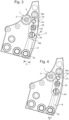
figures 3 et 4 sont des vues de dessus du mécanisme de positionnement selon l'invention dans deux positions de réglage différentes, - la
figure 5 est une vue de dessus du mécanisme de positionnement selon l'invention, la roue dentée étant dans une position de fonctionnement, et - la
figure 6 est une vue de dessus du mécanisme de positionnement selon l'invention, la roue dentée étant dans une position d'arrêt. - Dans la présente description, l'expression «roue dentée» doit être interprétée au sens large et désigne tout élément circulaire comprenant au moins un secteur denté, tel qu'un disque, une roue, une couronne, un pignon, etc...
- En référence aux
figures 1 et 2 , il est représenté un mécanisme de positionnement d'une roue dentée 1 montée sur un axe 2 mobile en rotation dans un mouvement horloger. La roue dentée 1 est agencée pour coopérer avec une autre denture d'un mécanisme du mouvement horloger (non représentés), notamment par période ou par cycle, la roue dentée 1 s'immobilisant à la fin de la période ou du cycle dans sa position initiale ou toute autre position prévue par le mécanisme. Notamment, la roue dentée 1 correspond par exemple aux pignons inverseurs 96-98 et 100 décrits dans la demandeWO 2014/176262 et prévus pour faire tourner la roue d'actionnement du bras dans le sens horaire et anti-horaire pendant son cycle de déplacement. Lorsque le bras a effectué un cycle de déplacement, les pignons inverseurs doivent revenir d'une manière certaine dans leur position initiale afin de pouvoir de nouveau engrener sans défaut avec les différentes dentures du mécanisme lors du cycle suivant. Dans la suite de la description, la roue dentée 1 correspond aux pignons inverseurs 96-98 ou 100 ou toute autre roue dentée d'un mécanisme horloger nécessitant plus particulièrement un repositionnement très précis des dents lorsque la roue dentée s'arrête après avoir pivoté d'un angle déterminé. - Afin de garantir un positionnement correct de la roue dentée 1 après son arrêt, il est prévu un levier de positionnement 3 présentant un bord latéral plat 4 agencé pour coopérer avec un plat 6 prévu sur l'axe 2 de la roue dentée 4. Le plat 6 est réalisé sur l'axe 2 de manière à se positionner en regard du bord latéral 4 du levier de positionnement 3 lorsque la roue dentée 1 s'arrête après avoir pivoté de l'angle déterminé.
- Selon l'invention, le levier de positionnement 3 comprend un bras de pivotement 8 agencé pour être monté pivotant autour d'un axe de pivotement 10 prévu dans le mouvement horloger. A cet effet, le bras de pivotement présente, à une extrémité, une bague 12 montée pivotante sur l'axe de pivotement 10. A son autre extrémité, soit son extrémité libre, le bras de pivotement 8 porte un élément de positionnement 14 qui présente le bord latéral plat 4. Plus précisément, l'élément de positionnement 14 est monté superposé sur le bras de pivotement 8 de manière à présenter une extrémité extérieure 14a présentant le bord latéral plat 4 en regard de l'axe 2 de la roue dentée 1 et une extrémité intérieure 14b en regard de l'axe de pivotement 10 du bras de pivotement 8. L'élément de positionnement 14 est monté articulé sur le bras de pivotement 8 par son extrémité extérieure 14a au moyen d'un pivot 16 prévu à l'extrémité libre du bras de pivotement 8 et monté traversant dans l'extrémité extérieure 14a de l'élément de positionnement 14.
- En référence plus spécifiquement aux
figures 3 à 6 , l'élément de positionnement 14 comprend entre son extrémité extérieure 14a et son extrémité intérieure 14b une première ouverture oblongue 18, disposée longitudinalement par rapport au bras de pivotement 8 et une seconde ouverture oblongue 20, disposée transversalement par rapport au bras de pivotement 8. Les première et seconde ouvertures oblongues 18, 20 sont reliées par un canal 23. La première ouverture 18 est agencée pour coopérer avec les moyens de réglage de la position de l'élément de positionnement 14 et la seconde ouverture 20 est agencée pour coopérer avec les moyens de verrouillage de la position de l'élément de positionnement 14. - Avantageusement, les moyens de réglage de la position de l'élément de positionnement 14 sur le bras de pivotement 8 par rapport à l'axe 2 de la roue dentée 1 comprennent un excentrique 22 monté sur le bras de pivotement 8 et agencé pour coopérer avec l'élément de positionnement 14. Plus particulièrement, l'excentrique 22 est monté sur le bras de pivotement 8 en se logeant dans la première ouverture oblongue 18 de manière à pouvoir coopérer avec les bords de ladite ouverture oblongue 18 pour faire pivoter l'élément de positionnement 14 autour du pivot 16 lors du réglage.
- De préférence, les moyens de verrouillage de la position de l'élément de positionnement 14 sur le bras de pivotement 8 par rapport à l'axe 2 de la roue dentée 1 comprennent une vis de serrage 24 montée sur le bras de pivotement 8 et agencée pour bloquer l'élément de positionnement 14 sur ledit bras de pivotement 8. Plus particulièrement, la vis de serrage 24 est montée sur le bras de pivotement 8 au travers de la seconde ouverture oblongue 20 de l'élément de positionnement 14. Ainsi, l'élément de positionnement 14 peut évoluer autour de la vis de serrage 24 lorsqu'il est pivoté pour le réglage.
- Il est également prévu un ressort de maintien 26 du bras de pivotement. Comme le montre la
figure 2 , le ressort de maintien 26 est monté sur l'axe de pivotement 10 et est accroché sur l'excentrique 22 monté sur le bras de pivotement 8. - Le fonctionnement du mécanisme de positionnement selon l'invention est le suivant : au moment du montage du mécanisme, l'élément de positionnement 14 est positionné de sorte que son bord latéral plat 4 soit aligné avec le plat 6 prévu sur l'axe 2 de la roue dentée 1 qui se présente en regard de l'élément de positionnement 14 lorsque la roue dentée 1 est dans une position correspondant à sa position arrêtée après avoir pivoté de l'angle déterminé. L'élément de positionnement 14 appuie sur le plat 6 afin de repositionner correctement la roue dentée 1 pour que sa denture puisse engrener sans défaut avec le mécanisme associé au prochain redémarrage de la roue dentée 1.
- Pour que l'effet du levier de positionnement 3 sur le plat 6 soit le plus efficace possible, il est nécessaire que le bord latéral plat 4 soit parfaitement aligné avec le plat 6. La position du levier de positionnement 3 doit donc être très finement réglée. A cet effet, l'élément de positionnement 14 est pivoté autour du pivot 16 au moyen de l'excentrique 22 coopérant avec les bords de la première ouverture oblongue 18 de manière à modifier plus ou moins la position angulaire α de l'élément de positionnement 14 par rapport au bras de positionnement 8, tel que représenté sur les
figures 3 et 4 . La seconde ouverture oblongue 20 permet le déplacement de l'élément de positionnement 14, tout en laissant la vis de réglage montée sur le bras de pivotement. Une fois la position angulaire α de l'élément de positionnement 14 réglée pour que le bord latéral plat 4 soit parfaitement aligné avec le plat 6, l'élément de positionnement 14 est fixé sur le bras de pivotement 8 au moyen de la vis de serrage 24. - En référence à la
figure 5 , lors du fonctionnement du mécanisme, le levier de positionnement 3 est soulevé par la face arrondie de l'axe 2 de la roue dentée 1. Lorsque la roue dentée 1 a pivoté de l'angle déterminé par rapport à la position du plat 6, le plat 6 arrive en regard du levier de pivotement 3 qui s'abaisse, ramené par son ressort de maintien 26. Lorsque la roue dentée 1 s'arrête, le bord latéral plat 4 de l'élément de pivotement 14 appuie alors sur le plat 6 de l'axe 2 pour repositionner la denture de la roue dentée 1, comme le montre lafigure 6 . L'alignement du bord latéral 4 de l'élément de pivotement 14 avec le plat 6 de l'axe 2 obtenu grâce au réglage très fin de l'élément de pivotement 14 permet le repositionnement exact de la roue dentée 1 pour que sa denture puisse engrener sans défaut avec le mécanisme associé au prochain redémarrage.
Claims (7)
- Mécanisme de positionnement d'une roue dentée (1) montée sur un axe (2) mobile en rotation dans un mouvement horloger, ledit mécanisme de positionnement comprenant un levier de positionnement (3) présentant un bord latéral (4) plat agencé pour coopérer avec au moins un plat (6) prévu sur l'axe (2) de la roue dentée (1), le levier de positionnement (3) comprenant un bras de pivotement (8) agencé pour être monté pivotant autour d'un axe de pivotement (10) prévu dans le mouvement horloger, un élément de positionnement (14) présentant le bord latéral (4) plat et monté articulé sur le bras de pivotement (8), et des moyens de réglage et de verrouillage de la position de l'élément de positionnement (14) sur le bras de pivotement (8) par rapport à l'axe (2) de la roue dentée (1), dans lequel l'élément de positionnement (14) comprend une première ouverture oblongue (18), disposée longitudinalement par rapport au bras de pivotement (8), agencée pour coopérer avec les moyens de réglage de la position de l'élément de positionnement (14) et une seconde ouverture oblongue (20), disposée transversalement par rapport au bras de pivotement (8), agencée pour coopérer avec les moyens de verrouillage de la position de l'élément de positionnement (14).
- Mécanisme selon la revendication 1, caractérisé en ce que l'élément de positionnement (14) est monté superposé sur le bras de pivotement (8) de manière à présenter une extrémité extérieure (14a) présentant le bord latéral (4) plat en regard de l'axe (2) de la roue dentée (1) et une extrémité intérieure (14b) en regard de l'axe de pivotement (10) du bras de pivotement (8).
- Mécanisme selon la revendication 2, caractérisé en ce que l'élément de positionnement (14) est monté articulé sur le bras de pivotement (8) par son extrémité extérieure (14a) au moyen d'un pivot (16) prévu sur ledit bras de pivotement (8).
- Mécanisme selon l'une des revendications précédentes, caractérisé en ce que les moyens de réglage de la position de l'élément de positionnement (14) sur le bras de pivotement (8) par rapport à l'axe (2) de la roue dentée (1) comprennent un excentrique (22) monté sur le bras de pivotement (8) et agencé pour coopérer avec l'élément de positionnement (14).
- Mécanisme selon l'une des revendications précédentes, caractérisé en ce que les moyens de verrouillage de la position de l'élément de positionnement (14) sur le bras de pivotement (8) par rapport à l'axe (2) de la roue dentée (1) comprennent une vis de serrage (24) montée sur le bras de pivotement (8) et agencée pour bloquer l'élément de positionnement (14) sur le bras de pivotement (8).
- Mécanisme selon l'une des revendications précédentes, caractérisé en ce qu'il comprend un ressort de maintien (26) du bras de pivotement (8).
- Mouvement horloger comprenant une roue dentée (1) montée sur un axe (2) mobile en rotation comprenant un mécanisme de positionnement selon l'une des revendications précédentes.
Applications Claiming Priority (2)
| Application Number | Priority Date | Filing Date | Title |
|---|---|---|---|
| EP15186692.8A EP3147728A1 (fr) | 2015-09-24 | 2015-09-24 | Mécanisme de positionnement d'une roue dentée dans un mouvement horloger |
| PCT/EP2016/072528 WO2017050888A1 (fr) | 2015-09-24 | 2016-09-22 | Mécanisme de positionnement d'une roue dentée dans un mouvement horloger |
Publications (2)
| Publication Number | Publication Date |
|---|---|
| EP3353607A1 EP3353607A1 (fr) | 2018-08-01 |
| EP3353607B1 true EP3353607B1 (fr) | 2024-08-21 |
Family
ID=54199052
Family Applications (2)
| Application Number | Title | Priority Date | Filing Date |
|---|---|---|---|
| EP15186692.8A Withdrawn EP3147728A1 (fr) | 2015-09-24 | 2015-09-24 | Mécanisme de positionnement d'une roue dentée dans un mouvement horloger |
| EP16770017.8A Active EP3353607B1 (fr) | 2015-09-24 | 2016-09-22 | Mécanisme de positionnement d'une roue dentée dans un mouvement horloger |
Family Applications Before (1)
| Application Number | Title | Priority Date | Filing Date |
|---|---|---|---|
| EP15186692.8A Withdrawn EP3147728A1 (fr) | 2015-09-24 | 2015-09-24 | Mécanisme de positionnement d'une roue dentée dans un mouvement horloger |
Country Status (5)
| Country | Link |
|---|---|
| US (1) | US10365613B2 (fr) |
| EP (2) | EP3147728A1 (fr) |
| JP (1) | JP6484758B2 (fr) |
| CN (1) | CN108351615B (fr) |
| WO (1) | WO2017050888A1 (fr) |
Families Citing this family (1)
| Publication number | Priority date | Publication date | Assignee | Title |
|---|---|---|---|---|
| EP3667435B1 (fr) | 2018-12-10 | 2022-06-01 | Montres Breguet S.A. | Systeme de reglage de la position d'un premier mobile dente par rapport a un support sur lequel le premier mobile dente est monte pivotant et piece d'horlogerie comprenant un tel systeme |
Family Cites Families (22)
| Publication number | Priority date | Publication date | Assignee | Title |
|---|---|---|---|---|
| CH227300A (fr) * | 1940-12-19 | 1943-05-31 | Jacot Guyot Henri | Chronographe. |
| CH271999A (fr) * | 1948-04-21 | 1950-11-30 | Vve James Aubert & Cie | Chronographe. |
| US3708973A (en) * | 1969-07-11 | 1973-01-09 | Sankyo Seiki Seisakusho Kk | Directly readable digital clock |
| US3701250A (en) * | 1970-12-28 | 1972-10-31 | Xerox Corp | Adjustable return mechanism for a watch |
| CH678911B5 (fr) * | 1990-04-12 | 1992-05-29 | Ebauchesfabrik Eta Ag | |
| CH690524A5 (fr) | 1995-10-31 | 2000-09-29 | Rolex Montres | Pièce d'horlogerie à mécanisme de chronographe. |
| DE10135110B4 (de) | 2001-07-19 | 2004-05-27 | Lange Uhren Gmbh | Chronograph |
| DE60210973T2 (de) * | 2002-10-04 | 2007-01-04 | Eta Sa Manufacture Horlogère Suisse | Kupplungsmechanismus für Chronographen |
| EP1746471B1 (fr) * | 2005-07-20 | 2019-09-18 | Breitling AG | Dispositif de remise à zéro de deux compteurs de temps |
| JP5168843B2 (ja) * | 2006-03-03 | 2013-03-27 | セイコーエプソン株式会社 | クロノグラフ時計 |
| CH698827B1 (fr) * | 2006-08-15 | 2009-11-13 | Chopard Manufacture Sa | Dispositif de remise à zéro pour une pièce d'horlogerie. |
| EP2073078B1 (fr) * | 2007-12-21 | 2012-11-07 | Omega SA | Marteau bistable pour mécanisme de chronographe |
| JP2011022043A (ja) * | 2009-07-16 | 2011-02-03 | Seiko Instruments Inc | クロノグラフ時計 |
| US20110021663A1 (en) * | 2009-07-23 | 2011-01-27 | Sacks Abraham J | Light weight aggregate composition |
| EP2363761B1 (fr) * | 2010-03-05 | 2016-05-18 | Montres Breguet SA | Dispositif de mesure du couple pour arrêt de sonnerie |
| EP2407830B1 (fr) * | 2010-07-15 | 2014-11-05 | Rolex Sa | Piece d'horlogerie |
| CH703935B1 (fr) * | 2010-10-04 | 2017-04-13 | Rolex Sa | Organe régulateur balancier-spiral, mouvement horloger et pièce d'horlogerie comportant un tel organe régulateur. |
| CH705231B1 (fr) * | 2011-07-13 | 2018-09-28 | Eta Sa Mft Horlogere Suisse | Mouvement d'horlogerie comprenant un module muni d'un mobile engrenant avec un autre mobile pivotant dans une base sur laquelle est montée le module. |
| CH707269B1 (fr) * | 2012-11-16 | 2018-07-13 | Winston Harry Sa | Méchanisme d'affichage de plusieurs informations horométriques différentes et pièce d'horlogerie comprenant un tel mécanisme. |
| US10400897B2 (en) | 2013-04-22 | 2019-09-03 | Dezurik, Inc. | Orbital seat in a butterfly valve |
| US9735634B2 (en) * | 2014-07-22 | 2017-08-15 | GM Global Technology Operations LLC | Split pole spoke type PM machine with enclosed magnets |
| EP3059642B1 (fr) * | 2015-02-23 | 2019-05-22 | Montres Breguet S.A. | Mécanisme de chronographe |
-
2015
- 2015-09-24 EP EP15186692.8A patent/EP3147728A1/fr not_active Withdrawn
-
2016
- 2016-09-22 US US15/758,959 patent/US10365613B2/en active Active
- 2016-09-22 WO PCT/EP2016/072528 patent/WO2017050888A1/fr not_active Ceased
- 2016-09-22 JP JP2018513866A patent/JP6484758B2/ja active Active
- 2016-09-22 CN CN201680055718.8A patent/CN108351615B/zh active Active
- 2016-09-22 EP EP16770017.8A patent/EP3353607B1/fr active Active
Also Published As
| Publication number | Publication date |
|---|---|
| HK1257759A1 (zh) | 2019-10-25 |
| CN108351615A (zh) | 2018-07-31 |
| JP6484758B2 (ja) | 2019-03-13 |
| US20180246470A1 (en) | 2018-08-30 |
| WO2017050888A1 (fr) | 2017-03-30 |
| CN108351615B (zh) | 2020-12-15 |
| US10365613B2 (en) | 2019-07-30 |
| EP3147728A1 (fr) | 2017-03-29 |
| JP2018527581A (ja) | 2018-09-20 |
| EP3353607A1 (fr) | 2018-08-01 |
Similar Documents
| Publication | Publication Date | Title |
|---|---|---|
| EP3026504A1 (fr) | Mécanisme de quantième annuel ou perpétuel et pièce d horlogerie en comportant application | |
| EP3483663A1 (fr) | Dispositif d'entraînement pour système de calendrier horloger | |
| EP3070537A1 (fr) | Base de temps comportant un echappement a impulsion directe et a force constante | |
| EP2503412A1 (fr) | Mouvement horloger comportant un dispositif à équation du temps marchante | |
| WO2023025630A1 (fr) | Pièce d'horlogerie comprenant un cadran présentant au moins une fenêtre et un dispositif d'obturation de ladite fenêtre | |
| EP2503407A2 (fr) | Mouvement horloger comportant un actionneur instantané commandé par le mouvement | |
| EP2813902A1 (fr) | Mécanisme de calendrier pour mouvement horloger | |
| CH713209B1 (fr) | Mécanisme d'affichage pour pièce d'horlogerie. | |
| WO2017050888A1 (fr) | Mécanisme de positionnement d'une roue dentée dans un mouvement horloger | |
| EP2884345B1 (fr) | Sautoir pour mouvement d'horlogerie | |
| EP3306415B1 (fr) | Mouvement d'horlogerie mecanique a detection de reserve de marche | |
| EP3026506B1 (fr) | Chronomètre avec sélecteur de vitesse | |
| EP2615503B1 (fr) | Mécanisme de commande d'un barillet pour mouvement horloger | |
| WO2010026216A1 (fr) | Mecanisme d'affichage d'une information periodique | |
| CH708338A2 (fr) | Mécanisme correcteur pas-à-pas. | |
| CH715773B1 (fr) | Système d'entraînement sécurisé, notamment pour un quantième horloger. | |
| CH706108A2 (fr) | Dispositif stop-secondes simplifié pour mouvement horloger. | |
| CH720214B1 (fr) | Mécanisme de commande de quantième d'un mouvement horloger | |
| EP4325301A1 (fr) | Mécanisme horloger comprenant un organe horloger rotatif et un dispositif à raideur angulaire prédéfinie | |
| CH370709A (fr) | Elément de bâti mince pour mouvement d'horlogerie | |
| CH715723B1 (fr) | Mécanisme de saut instantané d'un mobile d'affichage. | |
| CH702429A2 (fr) | Chronographe mono-poussoir. | |
| EP2339414A1 (fr) | Chronographe mono-poussoir | |
| CH716983A1 (fr) | Mécanisme horloger destiné à être entraîné suivant un nombre de pas variable. | |
| CH716774B9 (fr) | Dispositif horloger de couplage et d'indexation. |
Legal Events
| Date | Code | Title | Description |
|---|---|---|---|
| STAA | Information on the status of an ep patent application or granted ep patent |
Free format text: STATUS: UNKNOWN |
|
| STAA | Information on the status of an ep patent application or granted ep patent |
Free format text: STATUS: THE INTERNATIONAL PUBLICATION HAS BEEN MADE |
|
| PUAI | Public reference made under article 153(3) epc to a published international application that has entered the european phase |
Free format text: ORIGINAL CODE: 0009012 |
|
| STAA | Information on the status of an ep patent application or granted ep patent |
Free format text: STATUS: REQUEST FOR EXAMINATION WAS MADE |
|
| 17P | Request for examination filed |
Effective date: 20180424 |
|
| AK | Designated contracting states |
Kind code of ref document: A1 Designated state(s): AL AT BE BG CH CY CZ DE DK EE ES FI FR GB GR HR HU IE IS IT LI LT LU LV MC MK MT NL NO PL PT RO RS SE SI SK SM TR |
|
| AX | Request for extension of the european patent |
Extension state: BA ME |
|
| DAV | Request for validation of the european patent (deleted) | ||
| DAX | Request for extension of the european patent (deleted) | ||
| STAA | Information on the status of an ep patent application or granted ep patent |
Free format text: STATUS: EXAMINATION IS IN PROGRESS |
|
| 17Q | First examination report despatched |
Effective date: 20210827 |
|
| P01 | Opt-out of the competence of the unified patent court (upc) registered |
Effective date: 20230531 |
|
| GRAP | Despatch of communication of intention to grant a patent |
Free format text: ORIGINAL CODE: EPIDOSNIGR1 |
|
| STAA | Information on the status of an ep patent application or granted ep patent |
Free format text: STATUS: GRANT OF PATENT IS INTENDED |
|
| INTG | Intention to grant announced |
Effective date: 20240426 |
|
| GRAS | Grant fee paid |
Free format text: ORIGINAL CODE: EPIDOSNIGR3 |
|
| GRAA | (expected) grant |
Free format text: ORIGINAL CODE: 0009210 |
|
| STAA | Information on the status of an ep patent application or granted ep patent |
Free format text: STATUS: THE PATENT HAS BEEN GRANTED |
|
| AK | Designated contracting states |
Kind code of ref document: B1 Designated state(s): AL AT BE BG CH CY CZ DE DK EE ES FI FR GB GR HR HU IE IS IT LI LT LU LV MC MK MT NL NO PL PT RO RS SE SI SK SM TR |
|
| REG | Reference to a national code |
Ref country code: GB Ref legal event code: FG4D Free format text: NOT ENGLISH |
|
| REG | Reference to a national code |
Ref country code: CH Ref legal event code: EP |
|
| REG | Reference to a national code |
Ref country code: DE Ref legal event code: R096 Ref document number: 602016089013 Country of ref document: DE |
|
| REG | Reference to a national code |
Ref country code: IE Ref legal event code: FG4D Free format text: LANGUAGE OF EP DOCUMENT: FRENCH |
|
| REG | Reference to a national code |
Ref country code: LT Ref legal event code: MG9D |
|
| REG | Reference to a national code |
Ref country code: NL Ref legal event code: MP Effective date: 20240821 |
|
| PG25 | Lapsed in a contracting state [announced via postgrant information from national office to epo] |
Ref country code: NO Free format text: LAPSE BECAUSE OF FAILURE TO SUBMIT A TRANSLATION OF THE DESCRIPTION OR TO PAY THE FEE WITHIN THE PRESCRIBED TIME-LIMIT Effective date: 20241121 |
|
| REG | Reference to a national code |
Ref country code: AT Ref legal event code: MK05 Ref document number: 1716089 Country of ref document: AT Kind code of ref document: T Effective date: 20240821 |
|
| PG25 | Lapsed in a contracting state [announced via postgrant information from national office to epo] |
Ref country code: GR Free format text: LAPSE BECAUSE OF FAILURE TO SUBMIT A TRANSLATION OF THE DESCRIPTION OR TO PAY THE FEE WITHIN THE PRESCRIBED TIME-LIMIT Effective date: 20241122 Ref country code: NL Free format text: LAPSE BECAUSE OF FAILURE TO SUBMIT A TRANSLATION OF THE DESCRIPTION OR TO PAY THE FEE WITHIN THE PRESCRIBED TIME-LIMIT Effective date: 20240821 Ref country code: FI Free format text: LAPSE BECAUSE OF FAILURE TO SUBMIT A TRANSLATION OF THE DESCRIPTION OR TO PAY THE FEE WITHIN THE PRESCRIBED TIME-LIMIT Effective date: 20240821 Ref country code: PL Free format text: LAPSE BECAUSE OF FAILURE TO SUBMIT A TRANSLATION OF THE DESCRIPTION OR TO PAY THE FEE WITHIN THE PRESCRIBED TIME-LIMIT Effective date: 20240821 Ref country code: PT Free format text: LAPSE BECAUSE OF FAILURE TO SUBMIT A TRANSLATION OF THE DESCRIPTION OR TO PAY THE FEE WITHIN THE PRESCRIBED TIME-LIMIT Effective date: 20241223 |
|
| PG25 | Lapsed in a contracting state [announced via postgrant information from national office to epo] |
Ref country code: BG Free format text: LAPSE BECAUSE OF FAILURE TO SUBMIT A TRANSLATION OF THE DESCRIPTION OR TO PAY THE FEE WITHIN THE PRESCRIBED TIME-LIMIT Effective date: 20240821 |
|
| PG25 | Lapsed in a contracting state [announced via postgrant information from national office to epo] |
Ref country code: LV Free format text: LAPSE BECAUSE OF FAILURE TO SUBMIT A TRANSLATION OF THE DESCRIPTION OR TO PAY THE FEE WITHIN THE PRESCRIBED TIME-LIMIT Effective date: 20240821 |
|
| PG25 | Lapsed in a contracting state [announced via postgrant information from national office to epo] |
Ref country code: AT Free format text: LAPSE BECAUSE OF FAILURE TO SUBMIT A TRANSLATION OF THE DESCRIPTION OR TO PAY THE FEE WITHIN THE PRESCRIBED TIME-LIMIT Effective date: 20240821 Ref country code: IS Free format text: LAPSE BECAUSE OF FAILURE TO SUBMIT A TRANSLATION OF THE DESCRIPTION OR TO PAY THE FEE WITHIN THE PRESCRIBED TIME-LIMIT Effective date: 20241221 |
|
| PG25 | Lapsed in a contracting state [announced via postgrant information from national office to epo] |
Ref country code: HR Free format text: LAPSE BECAUSE OF FAILURE TO SUBMIT A TRANSLATION OF THE DESCRIPTION OR TO PAY THE FEE WITHIN THE PRESCRIBED TIME-LIMIT Effective date: 20240821 |
|
| PG25 | Lapsed in a contracting state [announced via postgrant information from national office to epo] |
Ref country code: RS Free format text: LAPSE BECAUSE OF FAILURE TO SUBMIT A TRANSLATION OF THE DESCRIPTION OR TO PAY THE FEE WITHIN THE PRESCRIBED TIME-LIMIT Effective date: 20241121 Ref country code: ES Free format text: LAPSE BECAUSE OF FAILURE TO SUBMIT A TRANSLATION OF THE DESCRIPTION OR TO PAY THE FEE WITHIN THE PRESCRIBED TIME-LIMIT Effective date: 20240821 |
|
| PG25 | Lapsed in a contracting state [announced via postgrant information from national office to epo] |
Ref country code: RS Free format text: LAPSE BECAUSE OF FAILURE TO SUBMIT A TRANSLATION OF THE DESCRIPTION OR TO PAY THE FEE WITHIN THE PRESCRIBED TIME-LIMIT Effective date: 20241121 Ref country code: PT Free format text: LAPSE BECAUSE OF FAILURE TO SUBMIT A TRANSLATION OF THE DESCRIPTION OR TO PAY THE FEE WITHIN THE PRESCRIBED TIME-LIMIT Effective date: 20241223 Ref country code: PL Free format text: LAPSE BECAUSE OF FAILURE TO SUBMIT A TRANSLATION OF THE DESCRIPTION OR TO PAY THE FEE WITHIN THE PRESCRIBED TIME-LIMIT Effective date: 20240821 Ref country code: NO Free format text: LAPSE BECAUSE OF FAILURE TO SUBMIT A TRANSLATION OF THE DESCRIPTION OR TO PAY THE FEE WITHIN THE PRESCRIBED TIME-LIMIT Effective date: 20241121 Ref country code: NL Free format text: LAPSE BECAUSE OF FAILURE TO SUBMIT A TRANSLATION OF THE DESCRIPTION OR TO PAY THE FEE WITHIN THE PRESCRIBED TIME-LIMIT Effective date: 20240821 Ref country code: LV Free format text: LAPSE BECAUSE OF FAILURE TO SUBMIT A TRANSLATION OF THE DESCRIPTION OR TO PAY THE FEE WITHIN THE PRESCRIBED TIME-LIMIT Effective date: 20240821 Ref country code: IS Free format text: LAPSE BECAUSE OF FAILURE TO SUBMIT A TRANSLATION OF THE DESCRIPTION OR TO PAY THE FEE WITHIN THE PRESCRIBED TIME-LIMIT Effective date: 20241221 Ref country code: HR Free format text: LAPSE BECAUSE OF FAILURE TO SUBMIT A TRANSLATION OF THE DESCRIPTION OR TO PAY THE FEE WITHIN THE PRESCRIBED TIME-LIMIT Effective date: 20240821 Ref country code: GR Free format text: LAPSE BECAUSE OF FAILURE TO SUBMIT A TRANSLATION OF THE DESCRIPTION OR TO PAY THE FEE WITHIN THE PRESCRIBED TIME-LIMIT Effective date: 20241122 Ref country code: FI Free format text: LAPSE BECAUSE OF FAILURE TO SUBMIT A TRANSLATION OF THE DESCRIPTION OR TO PAY THE FEE WITHIN THE PRESCRIBED TIME-LIMIT Effective date: 20240821 Ref country code: ES Free format text: LAPSE BECAUSE OF FAILURE TO SUBMIT A TRANSLATION OF THE DESCRIPTION OR TO PAY THE FEE WITHIN THE PRESCRIBED TIME-LIMIT Effective date: 20240821 Ref country code: BG Free format text: LAPSE BECAUSE OF FAILURE TO SUBMIT A TRANSLATION OF THE DESCRIPTION OR TO PAY THE FEE WITHIN THE PRESCRIBED TIME-LIMIT Effective date: 20240821 Ref country code: AT Free format text: LAPSE BECAUSE OF FAILURE TO SUBMIT A TRANSLATION OF THE DESCRIPTION OR TO PAY THE FEE WITHIN THE PRESCRIBED TIME-LIMIT Effective date: 20240821 |
|
| PG25 | Lapsed in a contracting state [announced via postgrant information from national office to epo] |
Ref country code: SM Free format text: LAPSE BECAUSE OF FAILURE TO SUBMIT A TRANSLATION OF THE DESCRIPTION OR TO PAY THE FEE WITHIN THE PRESCRIBED TIME-LIMIT Effective date: 20240821 Ref country code: RO Free format text: LAPSE BECAUSE OF FAILURE TO SUBMIT A TRANSLATION OF THE DESCRIPTION OR TO PAY THE FEE WITHIN THE PRESCRIBED TIME-LIMIT Effective date: 20240821 Ref country code: DK Free format text: LAPSE BECAUSE OF FAILURE TO SUBMIT A TRANSLATION OF THE DESCRIPTION OR TO PAY THE FEE WITHIN THE PRESCRIBED TIME-LIMIT Effective date: 20240821 |
|
| PG25 | Lapsed in a contracting state [announced via postgrant information from national office to epo] |
Ref country code: EE Free format text: LAPSE BECAUSE OF FAILURE TO SUBMIT A TRANSLATION OF THE DESCRIPTION OR TO PAY THE FEE WITHIN THE PRESCRIBED TIME-LIMIT Effective date: 20240821 |
|
| PG25 | Lapsed in a contracting state [announced via postgrant information from national office to epo] |
Ref country code: CZ Free format text: LAPSE BECAUSE OF FAILURE TO SUBMIT A TRANSLATION OF THE DESCRIPTION OR TO PAY THE FEE WITHIN THE PRESCRIBED TIME-LIMIT Effective date: 20240821 |
|
| PG25 | Lapsed in a contracting state [announced via postgrant information from national office to epo] |
Ref country code: IT Free format text: LAPSE BECAUSE OF FAILURE TO SUBMIT A TRANSLATION OF THE DESCRIPTION OR TO PAY THE FEE WITHIN THE PRESCRIBED TIME-LIMIT Effective date: 20240821 Ref country code: SK Free format text: LAPSE BECAUSE OF FAILURE TO SUBMIT A TRANSLATION OF THE DESCRIPTION OR TO PAY THE FEE WITHIN THE PRESCRIBED TIME-LIMIT Effective date: 20240821 |
|
| PG25 | Lapsed in a contracting state [announced via postgrant information from national office to epo] |
Ref country code: LU Free format text: LAPSE BECAUSE OF NON-PAYMENT OF DUE FEES Effective date: 20240922 |
|
| REG | Reference to a national code |
Ref country code: DE Ref legal event code: R097 Ref document number: 602016089013 Country of ref document: DE |
|
| PLBE | No opposition filed within time limit |
Free format text: ORIGINAL CODE: 0009261 |
|
| STAA | Information on the status of an ep patent application or granted ep patent |
Free format text: STATUS: NO OPPOSITION FILED WITHIN TIME LIMIT |
|
| PG25 | Lapsed in a contracting state [announced via postgrant information from national office to epo] |
Ref country code: MC Free format text: LAPSE BECAUSE OF FAILURE TO SUBMIT A TRANSLATION OF THE DESCRIPTION OR TO PAY THE FEE WITHIN THE PRESCRIBED TIME-LIMIT Effective date: 20240821 |
|
| REG | Reference to a national code |
Ref country code: BE Ref legal event code: MM Effective date: 20240930 |
|
| PG25 | Lapsed in a contracting state [announced via postgrant information from national office to epo] |
Ref country code: BE Free format text: LAPSE BECAUSE OF NON-PAYMENT OF DUE FEES Effective date: 20240930 |
|
| PG25 | Lapsed in a contracting state [announced via postgrant information from national office to epo] |
Ref country code: IE Free format text: LAPSE BECAUSE OF NON-PAYMENT OF DUE FEES Effective date: 20240922 |
|
| 26N | No opposition filed |
Effective date: 20250522 |
|
| PG25 | Lapsed in a contracting state [announced via postgrant information from national office to epo] |
Ref country code: SE Free format text: LAPSE BECAUSE OF FAILURE TO SUBMIT A TRANSLATION OF THE DESCRIPTION OR TO PAY THE FEE WITHIN THE PRESCRIBED TIME-LIMIT Effective date: 20240821 |
|
| REG | Reference to a national code |
Ref country code: CH Ref legal event code: U11 Free format text: ST27 STATUS EVENT CODE: U-0-0-U10-U11 (AS PROVIDED BY THE NATIONAL OFFICE) Effective date: 20251001 |
|
| PGFP | Annual fee paid to national office [announced via postgrant information from national office to epo] |
Ref country code: DE Payment date: 20250820 Year of fee payment: 10 |
|
| PGFP | Annual fee paid to national office [announced via postgrant information from national office to epo] |
Ref country code: GB Payment date: 20250820 Year of fee payment: 10 |
|
| PGFP | Annual fee paid to national office [announced via postgrant information from national office to epo] |
Ref country code: FR Payment date: 20250820 Year of fee payment: 10 |
|
| PGFP | Annual fee paid to national office [announced via postgrant information from national office to epo] |
Ref country code: CH Payment date: 20251001 Year of fee payment: 10 |
|
| PG25 | Lapsed in a contracting state [announced via postgrant information from national office to epo] |
Ref country code: CY Free format text: LAPSE BECAUSE OF FAILURE TO SUBMIT A TRANSLATION OF THE DESCRIPTION OR TO PAY THE FEE WITHIN THE PRESCRIBED TIME-LIMIT; INVALID AB INITIO Effective date: 20160922 |
|
| PG25 | Lapsed in a contracting state [announced via postgrant information from national office to epo] |
Ref country code: HU Free format text: LAPSE BECAUSE OF FAILURE TO SUBMIT A TRANSLATION OF THE DESCRIPTION OR TO PAY THE FEE WITHIN THE PRESCRIBED TIME-LIMIT; INVALID AB INITIO Effective date: 20160922 |