EP3352529B1 - Hotplate - Google Patents
Hotplate Download PDFInfo
- Publication number
- EP3352529B1 EP3352529B1 EP18151172.6A EP18151172A EP3352529B1 EP 3352529 B1 EP3352529 B1 EP 3352529B1 EP 18151172 A EP18151172 A EP 18151172A EP 3352529 B1 EP3352529 B1 EP 3352529B1
- Authority
- EP
- European Patent Office
- Prior art keywords
- transmission
- coils
- cooktop
- coil
- induction heating
- Prior art date
- Legal status (The legal status is an assumption and is not a legal conclusion. Google has not performed a legal analysis and makes no representation as to the accuracy of the status listed.)
- Active
Links
- 230000005540 biological transmission Effects 0.000 claims description 129
- 230000006698 induction Effects 0.000 claims description 63
- 238000010438 heat treatment Methods 0.000 claims description 52
- 238000004804 winding Methods 0.000 claims description 5
- 239000003990 capacitor Substances 0.000 claims description 4
- RYGMFSIKBFXOCR-UHFFFAOYSA-N Copper Chemical compound [Cu] RYGMFSIKBFXOCR-UHFFFAOYSA-N 0.000 claims description 3
- 230000004913 activation Effects 0.000 claims description 3
- 229910052802 copper Inorganic materials 0.000 claims description 3
- 239000010949 copper Substances 0.000 claims description 3
- 238000013461 design Methods 0.000 claims description 3
- 238000010411 cooking Methods 0.000 description 23
- 238000012546 transfer Methods 0.000 description 9
- 230000001939 inductive effect Effects 0.000 description 7
- 230000008878 coupling Effects 0.000 description 4
- 238000010168 coupling process Methods 0.000 description 4
- 238000005859 coupling reaction Methods 0.000 description 4
- 230000005284 excitation Effects 0.000 description 4
- 239000004020 conductor Substances 0.000 description 3
- 239000000463 material Substances 0.000 description 3
- 239000011810 insulating material Substances 0.000 description 2
- 238000004519 manufacturing process Methods 0.000 description 2
- 230000003287 optical effect Effects 0.000 description 2
- 239000002985 plastic film Substances 0.000 description 2
- 229920006255 plastic film Polymers 0.000 description 2
- 230000011664 signaling Effects 0.000 description 2
- 230000006978 adaptation Effects 0.000 description 1
- 238000004026 adhesive bonding Methods 0.000 description 1
- 238000013459 approach Methods 0.000 description 1
- 230000000712 assembly Effects 0.000 description 1
- 238000000429 assembly Methods 0.000 description 1
- 239000003985 ceramic capacitor Substances 0.000 description 1
- 230000008859 change Effects 0.000 description 1
- 239000011248 coating agent Substances 0.000 description 1
- 238000000576 coating method Methods 0.000 description 1
- 230000001419 dependent effect Effects 0.000 description 1
- 230000000694 effects Effects 0.000 description 1
- 238000010292 electrical insulation Methods 0.000 description 1
- 238000011156 evaluation Methods 0.000 description 1
- 239000011521 glass Substances 0.000 description 1
- 239000002241 glass-ceramic Substances 0.000 description 1
- 239000011159 matrix material Substances 0.000 description 1
- 238000000034 method Methods 0.000 description 1
- 238000012986 modification Methods 0.000 description 1
- 230000004048 modification Effects 0.000 description 1
- 239000004033 plastic Substances 0.000 description 1
- 230000008569 process Effects 0.000 description 1
- 239000004065 semiconductor Substances 0.000 description 1
Images

Classifications
-
- H—ELECTRICITY
- H05—ELECTRIC TECHNIQUES NOT OTHERWISE PROVIDED FOR
- H05B—ELECTRIC HEATING; ELECTRIC LIGHT SOURCES NOT OTHERWISE PROVIDED FOR; CIRCUIT ARRANGEMENTS FOR ELECTRIC LIGHT SOURCES, IN GENERAL
- H05B6/00—Heating by electric, magnetic or electromagnetic fields
- H05B6/02—Induction heating
- H05B6/06—Control, e.g. of temperature, of power
- H05B6/062—Control, e.g. of temperature, of power for cooking plates or the like
-
- H—ELECTRICITY
- H05—ELECTRIC TECHNIQUES NOT OTHERWISE PROVIDED FOR
- H05B—ELECTRIC HEATING; ELECTRIC LIGHT SOURCES NOT OTHERWISE PROVIDED FOR; CIRCUIT ARRANGEMENTS FOR ELECTRIC LIGHT SOURCES, IN GENERAL
- H05B2213/00—Aspects relating both to resistive heating and to induction heating, covered by H05B3/00 and H05B6/00
- H05B2213/03—Heating plates made out of a matrix of heating elements that can define heating areas adapted to cookware randomly placed on the heating plate
Definitions
- the invention relates to a hob with a hob plate and with at least one induction heating coil arranged thereon or below it, advantageously with several induction heating coils.
- an induction hob is known with a hob plate under which several induction heating coils are arranged. These cover an area which essentially corresponds to that of the hob plate or at least one heating area of the hob plate. It is thus possible for a cooking vessel of any size to be placed on the hob plate at any point and to be heated there with a power that can be specified by an operator.
- induction hobs are from the EP 1688018 B1 and the EP 2420105 B1 known with a large number of induction heating coils, for example in a regular arrangement with about 8 x 10 induction heating coils, with which it is also possible to place a cooking vessel at almost any point on a hob and heat it appropriately.
- an induction hob is known as a so-called matrix hob with a large number of induction heating coils arranged next to one another under a hob plate.
- a position and size of cooking vessels that have been set up can be recognized by means of a sensor unit. Adapted to this, the cooking vessels are heated by the corresponding number of covered induction heating coils.
- a household workstation such as a hob is known with several induction heating coils underneath.
- a cooking vessel placed above it can be inductively heated.
- a control unit for the household workstation can be placed over it and inductively supplied with energy.
- an induction hob with a plurality of induction heating coils arranged therebelow is known. These can be used alone or in groups to inductively heat a cooking vessel placed above it on a hob plate. For electrical Control of the individual induction heating coils relays are provided for connection to power electronics.
- the invention is based on the object of creating a hob mentioned at the beginning with which problems of the prior art can be solved and with which it is in particular possible to bring energy from an induction heating coil not only into a cooking vessel that fits directly above and in terms of size , but also in a cooking vessel which, in particular, is set up on a hob plate a little laterally offset from the coil.
- the hob has a hob plate, advantageously a flat hob plate made of hard glass or glass ceramic, on or under which at least one induction heating coil is arranged, advantageously several induction heating coils.
- the induction heating coils particularly advantageously cover a substantial area of the hob plate or at least the essential area of a heating area of the hob plate on which cooking vessels can be placed for heating.
- the induction heating coils can cover this area directly adjacent to one another except for a small distance. In particular, such a distance can be between 1 mm and 20 mm, particularly advantageously between 5 mm and 15 mm.
- a two-dimensionally extended transmission device is provided under the hob plate or between the at least one induction heating coil and the hob plate.
- the two-dimensional expansion of the transmission device means that it covers a considerably larger area than a single induction heating coil itself, whereby it at least partially covers it, in particular completely and / or protruding far beyond it.
- the transmission device it is particularly advantageous for the transmission device to have a two-dimensional extent which corresponds approximately to that of the hob plate or at least to its heating area as described above.
- the transmission device can mark or indicate the area in which cooking vessels for heating or cooking can be set up on the hob plate.
- the transmission device has a large number of resonant circuits which are inductively coupled to one another and which are responsible for the transmission of the energy.
- Each of the inductively coupled resonant circuits has a transmission coil and a transmission capacitance, so that an LC resonant circuit is formed.
- inductive energy generated by an induction coil or induction heating coil for heating a cooking vessel can be inductively transmitted to a cooking vessel very well and largely without losses.
- this cooking vessel does not have to be directly overlapping with the induction heating coil; rather, partial overlapping may be sufficient or it may also be possible that the cooking vessel does not cover the induction heating coil or its surface at all. A lateral energy transfer can thus take place by means of the transfer device.
- the transmission coils or the oscillating circuits run essentially in a surface or plane that is parallel to the hob plate.
- the energy is then transmitted inductively within this area or plane.
- operating elements and / or displays can be electrically supplied, controlled and / or evaluated by means of the transmission device.
- induction heating coils it is possible that a large part of the surface of the hob plate or the heating area does not have to be covered by induction heating coils, so that the structural effort and the effort for corresponding control of a large number of induction heating coils including cabling can be saved.
- even a few induction coils can be sufficient in order to be able to achieve a largely arbitrary covering of any position of a cooking vessel on the hob plate with the aid of the transmission device or its oscillating circuits. There is therefore no need to cover the entire heating area with induction heating coils.
- all resonant circuits or all transmission coils are designed identically. In particular, they are also arranged identically or in each case in the same direction.
- the electrical properties can also be advantageous the respective resonant circuits and in particular the transmission coils together with the transmission capacities must be the same.
- the transmission coils can have a largely rectangular shape, in particular be square. In this case, they can only be made somewhat rounded at the corners inside and outside for improved current conduction and easier manufacture.
- a transmission coil can have at least one turn which consists of a flat conductor track, in particular a flat copper track.
- Their width can be between 5 times and 100 times as large as their thickness.
- a width of the turn can be between 2% and 10% of the diameter of the transmission coil, in particular between 3% and 7%.
- a width of the turn is relatively large compared to the diameter, in particular compared to other inductive coils.
- this also serves to be able to keep the height of the transmission device relatively low, so that the overall height required for this in the induction hob below the hob plate does not become too great.
- a transmission coil can have several turns, advantageously a maximum of five turns. It is particularly advantageous to have a maximum of three turns in a multi-turn transmission coil.
- the turns then run in areas which are largely parallel to the area in which the transmission coils run as a whole or which is covered by the transmission device.
- the turns run helically one above the other. Due to the smallest possible height or thickness of the winding of the transmission coils, even including an insulating material between the turns running one above the other, there is only a relatively small overall height of a transmission coil.
- the efficiency of the energy transmission can be improved or adaptation to different operating frequencies can be facilitated.
- the transmission coils run in a common area and each have a small distance from one another. Gaps between the transmission coils should be a maximum of 5 mm wide, preferably a maximum of 2 mm. In this way, a good flat coverage is possible and, above all, good energy transfer due to the small distance. In this case, the transmission coils can largely cover or form the two-dimensional extent of the transmission device. If the transmission coils consist of bare conductor material as conductor tracks, for example as a copper track, an insulating material can also be provided between them in the lateral direction in order to avoid possible short circuits. This can also be achieved, for example, in that the flat transmission coils are embedded between two layers of plastic material, in particular plastic film. These can be laminated together so that the material of the plastic films is between two adjacent transmission coils, which can be glued or fused to one another to secure the position and for electrical insulation from one another.
- the transmission coils can be arranged next to one another in such a way that they largely cover the surface of the transmission device.
- a transmission coil can therefore have further transmission coils all around or along each straight outer side with a small spacing.
- neighboring transmission coils could even overlap, for example by running in different planes.
- An overlap can be between 1% and 10% of the diameter of the transmission coil, in particular between 3% and 7%, or between 1 mm and 20 mm.
- the transmission coils As an alternative to a largely covered surface of the transmission device by transmission coils closely spaced on several or all sides, provision can also be made for the transmission coils to be rectangular and only come close to each other in the corner areas and be close to each other, almost to abut each other or even here a little overlap as previously described. Then, so to speak, free areas are formed between the transmission coils or only every second grid space is occupied by a transmission coil in a narrow grid.
- a control for the at least one induction coil can be designed for a frequency between 17 kHz and 100 kHz, in particular between 20 kHz and 50 kHz.
- the energy transmission of the transmission coils then has to be optimized, whereby this can essentially correspond to a usual frequency range for induction hobs. This then makes it possible to fall back on the usual frequencies that are generated and handled in an induction hob, so that the already existing assemblies can be used.
- these relatively low frequencies can advantageously be achieved by changing or adapting the capacitance of the L-C oscillating circuits.
- the transmission capacitances of the LC resonant circuits are designed as SMD capacitors, in particular as SMD ceramic capacitors. This makes it possible to improve energy efficiency or transmission efficiency. With SMD capacitors with a small design, it is also possible, above all, to limit the overall height of the transmission device.
- a transmission device cannot or not only be used to transmit energy to cooking vessels that are offset from an induction heating coil, but also to control displays or optical signaling means, in particular LEDs, which can be arranged at any point under the hob plate.
- a resonant circuit As a type of electrical consumer, it can be connected to a resonant circuit and supplied with energy for lighting or controlled in essentially any known manner.
- the desired resonant circuit of a certain LED can be controlled by appropriate control or feeding of energy into the transmission device, for example by means of an induction heating coil or a separate excitation coil, and by tuning the frequency so that it lights up .
- a resonant circuit with an LED connected or coupled to it can have a specific resonance frequency. A specific LED can then be selectively controlled by controlling the transmission device at variable frequencies.
- a sensor in a further embodiment, it is possible for a sensor to be connected to at least one transmission coil or to at least one resonant circuit.
- This is advantageously a capacitive touch sensor, as is known, for example, for operating elements on a hob plate, see, for example, FIG EP 859467 A2 .
- capacitive touch sensors or also temperature sensors with a temperature-dependent resistance value resonance frequencies of an oscillating circuit can be influenced or detuned differently. This can then be detected on an energy coupling or activation of the transmission device, in particular on an induction heating coil or an aforementioned excitation coil. In this way, the temperature can also be measured over an area or several touch sensors distributed over the hob plate can be queried or operated as operating elements.
- the oscillating circuit When a cooking vessel is placed on the hob, the oscillating circuit is detuned or the resulting inductive coupling changes the effective resistance. As a result, the power is tapped at the place where this detuning takes place.
- the effective resistance of an induction heating coil changes when a cooking vessel is put on from 0.025 ohms to approx. 5 ohms due to the inductive coupling. In this way, power can be introduced into the cooking vessel that has been set up, advantageously in the case of an induction hob.
- any hob in the context of the invention, it should also be possible for any hob to be provided with such a transmission device under a hob plate, for example a gas hob. Then at least one previously described excitation coil is necessary for the transmission device.
- the transmission device should then not be provided here for inductive energy transmission, but rather for control and / or evaluation for the aforementioned optical signaling means or LEDs or touch sensors of operating elements. Then a separate excitation coil has to be provided for the transmission device.
- the transmission device then does not serve to transmit inductive energy to a cooking vessel placed on the hob plate, for which purpose a gas burner would then be provided. Rather, different, distributed temperature sensors and / or operating elements with capacitive touch sensors or the like are intended. can be evaluated.
- a hob according to the invention is shown in simplified form as an induction hob 11 in a side section, the induction hob 11 having a hob plate 13 corresponding to a conventional design, on the underside of which a flat housing 15 is arranged.
- Flat induction heating coils 17 are arranged in the housing 15 as shown in FIG Fig. 2 , so with an essentially rectangular basic shape and a small distance from one another. This is for example from the DE 102014224051 A1 known, to which reference is made explicitly in this regard.
- the induction heating coils 17 rest on a support plate 18. Under the support plate 18, the housing 15 has schematically illustrated units for a control 19 and a power supply 20.
- the control 19 also contains control intelligence for the induction hob 11.
- FIG. 2 the top view of the Fig. 2 recognizable display 23 and control elements 25 are controlled and evaluated. This is known per se from the prior art. From the Fig. 2 Additional control elements 26 shown in the rear area can be seen, which are advantageously designed, similar to the control elements 25, as capacitive touch switches with capacitive touch sensors. Likewise, round lights 27 shown in dotted lines are provided between the two rear rows of induction heating coils 17. With these lights 27, their activation status can be displayed, alternatively also, for example, a residual heat indicator or the like. will be realized.
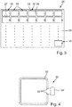
- FIG Fig. 3 shown in plan view. It is like the sectional view of the Fig. 1 already shows very flat and has, for example, a thin carrier 29, which can even be formed like a film.
- the LC oscillating circuits 30 can be applied directly to this carrier 29, even as a film, either by gluing on or by direct coating or also printing. Appropriate processes are familiar to the person skilled in the art and do not present any problems whatsoever. It can be seen that the LC resonant circuits 30 each have a transmission coil 32 and a transmission capacity 34. When displaying the Fig.
- the carrier 29 is to be provided with such LC oscillating circuits 30 largely over the entire surface, in particular except for the area of the display 23 and the front operating elements 25. For the sake of clarity, however, not all are shown. In the front area of the induction hob 11 on the display 23 and the operating elements 25, the LC oscillating circuits 30 can also be saved.
- All L-C resonant circuits 30 are advantageously designed identically. As can be seen, they are each aligned or arranged in the same way. This does not necessarily have to be the case, but has proven to be advantageous for good energy transmission within the transmission device.
- the distance between adjacent LC resonant circuits 30 or, above all, the transmission coils 32 can be relatively small and, for example, between 1 mm and 15 mm, advantageously between 2 mm and 10 mm. This applies both to transmission coils 32 arranged laterally next to one another and to those arranged one behind the other. The distance should be so small that they are inductively coupled to one another in every direction in any case. In one embodiment of the invention, it is even conceivable that different transmission coils 32, in particular adjacent ones, run in different planes and even overlap in plan view, see in this regard Fig. 5 .
- an LC resonant circuit 30 ' is shown in enlargement, as it could be designed in practice. It has a transmission coil 32 'which consists of a single turn, the coil ends 33' of which are not completely closed or are at a small distance from one another.
- a transmission capacity 34 ' is connected to these coil ends 33', this transmission capacity advantageously being a discrete component, for example an SMD component.
- the capacity can be in the range of ⁇ 1 ⁇ F.
- the transfer device 28 can be used to transfer energy from one of the induction heating coils 17 to another.
- the induction heating coils 17 could be saved in some areas of the induction hob 11 or have a greater distance from one another, so that there the transmission coils 32 at least partially take over the energy transmission into an installed cooking vessel.
- a lighting system 27 it is possible for energy to be transmitted to a lighting system 27.
- This can have an LED with an oscillating circuit that is tuned to a specific resonance frequency.
- energy can then be coupled in with a specific frequency which, due to the special resonance frequency of the lighting 27, only causes it to light up, but not other provided lighting devices with a resonance frequency different therefrom. Both types of energy transfer take place via the resonant circuit detuning described above.
- Additional operating elements 26 can be activated in a similar manner. Especially when these have capacitive touch sensors, which change their capacitance when a finger is placed on the top of the hob plate 13 and thus detune an oscillating circuit, various feedbacks can be used to determine which of the additional operating elements 26 has been operated and thus detuned. For this, too, there is no need for complex cabling to the respective locations of the additional operating elements 26, which, due to their arrangement in the heating area of the induction hob 11, could cause additional problems due to excessively high temperatures.
- This energy transfer to lighting 27 as a display and / or the control of additional operating elements 26 can also be used in any cooktop, for example with radiant heating elements or gas burners.
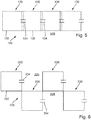
- the Fig. 5 shows a simplified representation based on the Figures 3 and 4 , as in the case of a transmission device 128, adjacent transmission coils 132 of LC resonant circuits 130 overlap one another in a simple manner. For this purpose, these are alternately arranged on an upper side and a lower side of the carrier 129, specifically the LC resonant circuits 130 shown in solid lines on an upper side and the LC resonant circuits 130 shown in dashed lines on a lower side.
- An overlap can then be in the range from 0.5 cm to 2 cm if the transmission coils 132 have a length and / or width in the range between 10 cm and 30 cm, in particular between 15 cm and 25 cm.
- the Fig. 6 shows in a simplified representation how in a transmission device 228 LC resonant circuits 230 or especially the transmission coils 232 are arranged on the carrier 229 of the transmission device 228 in such a way that, so to speak, every second field in a row and in a column is not occupied.
- adjacent transmission coils 232 only approach one another in their corner regions or run close to one another, which still results in a sufficient inductive coupling for the transmission device 228.
Description
Die Erfindung betrifft ein Kochfeld mit einer Kochfeldplatte und mit mindestens einer daran oder darunter angeordneten Induktionsheizspule, vorteilhaft mit mehreren Induktionsheizspulen.The invention relates to a hob with a hob plate and with at least one induction heating coil arranged thereon or below it, advantageously with several induction heating coils.
Aus der
Des Weiteren sind Induktionskochfelder aus der
Aus der
Aus der
Aus der
Der Erfindung liegt die Aufgabe zugrunde, ein eingangs genanntes Kochfeld zu schaffen, mit dem Probleme des Standes der Technik gelöst werden können und mit dem es insbesondere möglich ist, Energie von einer Induktionsheizspule nicht nur in ein direkt darüber und von der Größe her passendes Kochgefäß einzubringen, sondern auch in ein Kochgefäß, welches insbesondere in seitlicher Richtung ein Stück zu der Spule versetzt auf eine Kochfeldplatte aufgestellt ist.The invention is based on the object of creating a hob mentioned at the beginning with which problems of the prior art can be solved and with which it is in particular possible to bring energy from an induction heating coil not only into a cooking vessel that fits directly above and in terms of size , but also in a cooking vessel which, in particular, is set up on a hob plate a little laterally offset from the coil.
Gelöst wird diese Aufgabe durch ein Kochfeld mit den Merkmalen des Anspruchs 1. Vorteilhafte sowie bevorzugte Ausgestaltungen der Erfindung sind Gegenstand der weiteren Ansprüche und werden im Folgenden näher erläutert. Der Wortlaut der Ansprüche wird durch ausdrückliche Bezugnahme zum Inhalt der Beschreibung gemacht.This object is achieved by a hob with the features of claim 1. Advantageous and preferred embodiments of the invention are the subject matter of the further claims and are explained in more detail below. The wording of the claims is made part of the content of the description by express reference.
Es ist vorgesehen, dass das Kochfeld eine Kochfeldplatte aufweist, vorteilhaft eine ebene Kochfeldplatte aus Hartglas oder Glaskeramik, an der oder unter der mindestens eine Induktionsheizspule angeordnet ist, vorteilhaft mehrere Induktionsheizspulen. Besonders vorteilhaft bedecken die Induktionsheizspulen eine wesentliche Fläche der Kochfeldplatte bzw. zumindest die wesentliche Fläche eines Heizbereichs der Kochfeldplatte, auf der Kochgefäße zum Beheizen aufgestellt werden können. Dabei können in einer Ausgestaltung der Erfindung die Induktionsheizspulen bis auf einen geringen Abstand zueinander direkt benachbart diese Fläche bedecken. Insbesondere kann ein solcher Abstand zwischen 1 mm und 20 mm liegen, besonders vorteilhaft zwischen 5 mm und 15 mm.It is provided that the hob has a hob plate, advantageously a flat hob plate made of hard glass or glass ceramic, on or under which at least one induction heating coil is arranged, advantageously several induction heating coils. The induction heating coils particularly advantageously cover a substantial area of the hob plate or at least the essential area of a heating area of the hob plate on which cooking vessels can be placed for heating. In one embodiment of the invention, the induction heating coils can cover this area directly adjacent to one another except for a small distance. In particular, such a distance can be between 1 mm and 20 mm, particularly advantageously between 5 mm and 15 mm.
Erfindungsgemäß ist vorgesehen, dass unter der Kochfeldplatte bzw. zwischen der mindestens einen Induktionsheizspule und der Kochfeldplatte eine flächig ausgedehnte Übertragungsvorrichtung vorgesehen ist. Die flächige Ausdehnung der Übertragungsvorrichtung bedeutet, dass sie eine erheblich größere Fläche bedeckt als eine einzige Induktionsheizspule selbst, wobei sie diese zumindest teilweise überdeckt, insbesondere vollständig und/oder weit überragend. Besonders vorteilhaft weist die Übertragungsvorrichtung eine flächige Ausdehnung auf, die in etwa derjenigen der Kochfeldplatte oder zumindest ihres vorbeschriebenen Heizbereichs entspricht. Somit kann die Übertragungsvorrichtung mit ihrer flächigen Ausdehnung den Bereich markieren oder angeben, in dem auf der Kochfeldplatte Kochgefäße zum Beheizen bzw. Kochen aufgestellt werden können. Die Übertragungsvorrichtung weist eine Vielzahl von induktiv aneinander gekoppelten Schwingkreisen auf, die für die Übertragung der Energie zuständig sind. Jeder der induktiv gekoppelten Schwingkreise weist eine Übertragungsspule und eine Übertragungskapazität auf, so dass ein L-C-Schwingkreis gebildet wird. Damit kann von einer Induktionsspule bzw. Induktionsheizspule erzeugte induktive Energie zum Beheizen eines Kochgefäßes sehr gut und weitgehend verlustfrei induktiv übertragen werden an ein Kochgefäß. Dazu muss dieses Kochgefäß nicht direkt in Überdeckung mit der Induktionsheizspule sein, vielmehr kann eine teilweise Überdeckung ausreichen oder es kann auch möglich sein, dass das Kochgefäß die Induktionsheizspule bzw. deren Fläche überhaupt nicht überdeckt. Somit kann mittels der Übertragungsvorrichtung eine seitliche Energieübertragung erfolgen. Dazu verlaufen die Übertragungsspulen bzw. die Schwingkreise im Wesentlichen in einer Fläche oder Ebene, die parallel ist zu der Kochfeldplatte. Innerhalb dieser Fläche oder Ebene wird dann eben die Energie induktiv übertragen. Alternativ können mittels der Übertragungsvorrichtung Bedienelemente und/oder Anzeigen elektrisch versorgt, angesteuert und/oder ausgewertet werden.According to the invention it is provided that a two-dimensionally extended transmission device is provided under the hob plate or between the at least one induction heating coil and the hob plate. The two-dimensional expansion of the transmission device means that it covers a considerably larger area than a single induction heating coil itself, whereby it at least partially covers it, in particular completely and / or protruding far beyond it. It is particularly advantageous for the transmission device to have a two-dimensional extent which corresponds approximately to that of the hob plate or at least to its heating area as described above. Thus, with its two-dimensional extension, the transmission device can mark or indicate the area in which cooking vessels for heating or cooking can be set up on the hob plate. The transmission device has a large number of resonant circuits which are inductively coupled to one another and which are responsible for the transmission of the energy. Each of the inductively coupled resonant circuits has a transmission coil and a transmission capacitance, so that an LC resonant circuit is formed. In this way, inductive energy generated by an induction coil or induction heating coil for heating a cooking vessel can be inductively transmitted to a cooking vessel very well and largely without losses. For this purpose, this cooking vessel does not have to be directly overlapping with the induction heating coil; rather, partial overlapping may be sufficient or it may also be possible that the cooking vessel does not cover the induction heating coil or its surface at all. A lateral energy transfer can thus take place by means of the transfer device. For this purpose, the transmission coils or the oscillating circuits run essentially in a surface or plane that is parallel to the hob plate. The energy is then transmitted inductively within this area or plane. Alternatively, operating elements and / or displays can be electrically supplied, controlled and / or evaluated by means of the transmission device.
Weitere Informationen zu gekoppelten Übertragungsspulen bzw. gekoppelten Schwingkreisen und einer Energieübertragung kann der Fachmann unter anderem in der Literatur zu "Magnetoinductive waveguides" finden, wie beispielsweise in der
In diesem Zusammenhang spricht man unter anderem aufgrund der Ähnlichkeit zu Phononen-Modellen auch von Metamaterialien und "wireless power transfer".In this context one speaks of metamaterials and "wireless power transfer", among other things because of the similarity to phonon models.
Auf diese Art und Weise ist es möglich, dass nicht ein Großteil der Fläche der Kochfeldplatte bzw. des Heizbereichs von Induktionsheizspulen bedeckt sein muss, so dass der konstruktive Aufwand sowie der Aufwand für entsprechende Ansteuerung einer Vielzahl von Induktionsheizspulen samt Verkabelung eingespart werden kann. So können auch wenige Induktionsspulen ausreichend sein, um mit Hilfe der Übertragungsvorrichtung bzw. deren Schwingkreisen dennoch eine weitgehend beliebige Abdeckung jeder Position eines Kochgefäßes auf der Kochfeldplatte erreichen zu können. Es wird also keine flächendeckende Bedeckung des Heizbereichs mit Induktionsheizspulen benötigt.In this way, it is possible that a large part of the surface of the hob plate or the heating area does not have to be covered by induction heating coils, so that the structural effort and the effort for corresponding control of a large number of induction heating coils including cabling can be saved. Thus, even a few induction coils can be sufficient in order to be able to achieve a largely arbitrary covering of any position of a cooking vessel on the hob plate with the aid of the transmission device or its oscillating circuits. There is therefore no need to cover the entire heating area with induction heating coils.
In vorteilhafter Ausgestaltung der Erfindung kann es möglich sein, dass einzelne Schwingkreise, insbesondere die Übertragungsspulen oder eine elektrische Verbindung zwischen einer Übertragungsspule und einer Übertragungskapazität, schaltbar ausgebildet sind. Hierfür können einerseits Relais und andererseits Halbleiterschalter verwendet werden. Durch eine solche Schaltbarkeit kann erreicht werden, dass ein Schwingkreis sozusagen deaktiviert wird und eine Energieübertragung nicht über ihn hinaus erfolgt. Das kann für eine gezieltere Energieübertragung sorgen hin zu einem Ort, an der ein auf die Kochfeldplatte aufgestelltes Kochgefäß erkannt worden ist.In an advantageous embodiment of the invention, it can be possible for individual resonant circuits, in particular the transmission coils or an electrical connection between a transmission coil and a transmission capacitance, to be designed to be switchable. Relays on the one hand and semiconductor switches on the other hand can be used for this purpose. Such switchability can ensure that an oscillating circuit is deactivated, so to speak, and energy is not transferred beyond it. This can ensure a more targeted energy transfer to a place where a cooking vessel placed on the hob has been recognized.
In Ausgestaltung der Erfindung kann vorgesehen sein, dass sämtliche Schwingkreise bzw. sämtliche Übertragungsspulen identisch ausgebildet sind. Insbesondere sind sie auch identisch oder jeweils gleich ausgerichtet angeordnet. Vorteilhaft können auch die elektrischen Eigenschaften der jeweiligen Schwingkreise und insbesondere der Übertragungsspulen samt den Übertragungskapazitäten gleich sein.In an embodiment of the invention it can be provided that all resonant circuits or all transmission coils are designed identically. In particular, they are also arranged identically or in each case in the same direction. The electrical properties can also be advantageous the respective resonant circuits and in particular the transmission coils together with the transmission capacities must be the same.
In Ausgestaltung der Erfindung können die Übertragungsspulen eine weitgehend rechteckige Form aufweisen, insbesondere quadratisch sein. Dabei können sie lediglich an den Ecken innen und außen etwas abgerundet ausgebildet sein für eine verbesserte Stromführung und leichtere Herstellbarkeit.In an embodiment of the invention, the transmission coils can have a largely rectangular shape, in particular be square. In this case, they can only be made somewhat rounded at the corners inside and outside for improved current conduction and easier manufacture.
Eine Übertragungsspule kann mindestens eine Windung aufweisen, die aus einer flachen Leiterbahn besteht, insbesondere einer flachen Kupferbahn. Ihre Breite kann zwischen 5 x und 100 x so groß sein wie ihre Dicke. Eine Breite der Windung kann zwischen 2% und 10% des Durchmessers der Übertragungsspule betragen, insbesondere zwischen 3% und 7%. Somit ist eine Breite der Windung relativ groß im Vergleich zum Durchmesser, insbesondere verglichen mit anderen induktiven Spulen. Dies dient aber auch dazu, eine Höhe der Übertragungsvorrichtung relativ gering halten zu können, so dass eine hierfür benötigte Bauhöhe in dem Induktionskochfeld unterhalb der Kochfeldplatte nicht zu groß wird.A transmission coil can have at least one turn which consists of a flat conductor track, in particular a flat copper track. Their width can be between 5 times and 100 times as large as their thickness. A width of the turn can be between 2% and 10% of the diameter of the transmission coil, in particular between 3% and 7%. Thus, a width of the turn is relatively large compared to the diameter, in particular compared to other inductive coils. However, this also serves to be able to keep the height of the transmission device relatively low, so that the overall height required for this in the induction hob below the hob plate does not become too great.
In weiterer Ausgestaltung der Erfindung kann eine Übertragungsspule mehrere Windungen aufweisen, vorteilhaft maximal fünf Windungen. Besonders vorteilhaft sind es maximal drei Windungen bei einer mehrwindigen Übertragungsspule. Die Windungen verlaufen dann in Flächen, die weitgehend parallel sind zu derjenigen Fläche, in der die Übertragungsspulen insgesamt verlaufen bzw. die von der Übertragungsvorrichtung bedeckt wird. Die Windungen verlaufen also schraubenartig übereinander. Aufgrund einer möglichst geringen Höhe bzw. Dicke der Windung der Übertragungsspulen ergibt sich hier selbst inklusive einem isolierenden Material zwischen den übereinander verlaufenden Windungen nur eine insgesamt relativ geringe Höhe einer Übertragungsspule. Durch das Vorsehen von mehr als einer Windung mindestens einer der Übertragungsspulen kann eine Effizienz der Energieübertragung verbessert werden bzw. eine Anpassung an unterschiedliche Betriebsfrequenzen kann erleichtert werden.In a further embodiment of the invention, a transmission coil can have several turns, advantageously a maximum of five turns. It is particularly advantageous to have a maximum of three turns in a multi-turn transmission coil. The turns then run in areas which are largely parallel to the area in which the transmission coils run as a whole or which is covered by the transmission device. The turns run helically one above the other. Due to the smallest possible height or thickness of the winding of the transmission coils, even including an insulating material between the turns running one above the other, there is only a relatively small overall height of a transmission coil. By providing more than one turn of at least one of the transmission coils, the efficiency of the energy transmission can be improved or adaptation to different operating frequencies can be facilitated.
In Ausgestaltung der Erfindung kann vorgesehen sein, dass die Übertragungsspulen in einer gemeinsamen Fläche verlaufen und jeweils geringen Abstand zueinander aufweisen. Lücken zwischen den Übertragungsspulen sollten maximal 5 mm breit sein, vorzugsweise maximal 2 mm. So ist eine gute flächige Abdeckung möglich sowie vor allem durch den geringen Abstand eine gute Energieübertragung. Dabei können die Übertragungsspulen eben die flächige Ausdehnung der Übertragungsvorrichtung weitgehend bedecken oder bilden. Wenn die Übertragungsspulen aus blankem Leitermaterial als Leiterbahnen bestehen, beispielsweise als Kupferbahn, so kann auch in seitlicher Richtung zwischen ihnen ein isolierendes Material vorgesehen sein um mögliche Kurzschlüsse zu vermeiden. Dies kann beispielsweise auch dadurch erreicht werden, dass die flachen Übertragungsspulen zwischen zwei Lagen Kunststoffmaterial, insbesondere Kunststofffolie, eingebettet sind. Diese können zusammen laminiert werden, so dass zwischen zwei benachbarten Übertragungsspulen das Material der Kunststofffolien ist, welches miteinander verklebt oder verschmolzen sein kann zur Lagesicherung und zur elektrischen Isolierung gegeneinander.In an embodiment of the invention it can be provided that the transmission coils run in a common area and each have a small distance from one another. Gaps between the transmission coils should be a maximum of 5 mm wide, preferably a maximum of 2 mm. In this way, a good flat coverage is possible and, above all, good energy transfer due to the small distance. In this case, the transmission coils can largely cover or form the two-dimensional extent of the transmission device. If the transmission coils consist of bare conductor material as conductor tracks, for example as a copper track, an insulating material can also be provided between them in the lateral direction in order to avoid possible short circuits. This can also be achieved, for example, in that the flat transmission coils are embedded between two layers of plastic material, in particular plastic film. These can be laminated together so that the material of the plastic films is between two adjacent transmission coils, which can be glued or fused to one another to secure the position and for electrical insulation from one another.
Die Übertragungsspulen können derart nebeneinander angeordnet sein, dass sie die Fläche der Übertragungsvorrichtung weitgehend bedecken. Eine Übertragungsspule kann also ringsum bzw. entlang jeder geraden Außenseite mit geringem Abstand weitere Übertragungsspulen haben. Hierbei könnten sich benachbarte Übertragungsspulen sogar überlappen, beispielsweise indem sie in unterschiedlichen Ebenen verlaufen. Eine Überlappung kann zwischen 1% und 10% des Durchmessers der Übertragungsspule betragen, insbesondere zwischen 3% und 7%, bzw. zwischen 1 mm und 20 mm.The transmission coils can be arranged next to one another in such a way that they largely cover the surface of the transmission device. A transmission coil can therefore have further transmission coils all around or along each straight outer side with a small spacing. Here, neighboring transmission coils could even overlap, for example by running in different planes. An overlap can be between 1% and 10% of the diameter of the transmission coil, in particular between 3% and 7%, or between 1 mm and 20 mm.
Alternativ zu einer weitgehend bedeckten Fläche der Übertragungsvorrichtung durch jeweils an mehreren oder allen Seiten eng benachbarte Übertragungsspulen kann auch vorgesehen sein, dass die Übertragungsspulen rechteckig ausgebildet sind und sich nur an den Eckbereichen nahekommen und geringen Abstand zueinander aufweisen, nahezu aneinander anstoßen oder sich auch hier etwas überlappen wie zuvor beschrieben. Dann sind sozusagen freie Bereiche zwischen den Übertragungsspulen gebildet bzw. in einem engen Raster ist nur jeder zweite Rasterplatz von einer Übertragungsspule belegt.As an alternative to a largely covered surface of the transmission device by transmission coils closely spaced on several or all sides, provision can also be made for the transmission coils to be rectangular and only come close to each other in the corner areas and be close to each other, almost to abut each other or even here a little overlap as previously described. Then, so to speak, free areas are formed between the transmission coils or only every second grid space is occupied by a transmission coil in a narrow grid.
Eine Ansteuerung für die mindestens eine Induktionsspule kann für eine Frequenz zwischen 17 kHz und 100 kHz ausgelegt sein, insbesondere zwischen 20 kHz und 50 kHz. Darauf ist dann die Energieübertragung der Übertragungsspulen zu optimieren, wobei dies im Wesentlichen einem üblichen Frequenzbereich für Induktionskochfelder entsprechen kann. Damit kann dann auf übliche Frequenzen zurückgegriffen werden, die in einem Induktionskochfeld erzeugt und gehandhabt werden, so dass die bereits vorhandenen Baugruppen verwendet werden können. Im Vergleich zu dem vorgenannten bekannten Stand der Technik können diese relativ dazu niedrigen Frequenzen vorteilhaft durch Änderung bzw. Anpassung der Kapazität der der L-C-Schwingkreise erreicht werden.A control for the at least one induction coil can be designed for a frequency between 17 kHz and 100 kHz, in particular between 20 kHz and 50 kHz. The energy transmission of the transmission coils then has to be optimized, whereby this can essentially correspond to a usual frequency range for induction hobs. This then makes it possible to fall back on the usual frequencies that are generated and handled in an induction hob, so that the already existing assemblies can be used. In comparison to the aforementioned known prior art, these relatively low frequencies can advantageously be achieved by changing or adapting the capacitance of the L-C oscillating circuits.
In Ausgestaltung der Erfindung ist es möglich, dass die Übertragungskapazitäten der L-C-Schwingkreise als SMD-Kondensatoren ausgebildet sind, insbesondere als SMD-Keramikkondensatoren. Dadurch lässt sich eine Energieeffizienz bzw. Übertragungseffizienz verbessern. Durch SMD-Kondensatoren mit kleiner Bauweise lässt sich auch vor allem eine Bauhöhe der Übertragungsvorrichtung begrenzen.In an embodiment of the invention, it is possible that the transmission capacitances of the LC resonant circuits are designed as SMD capacitors, in particular as SMD ceramic capacitors. This makes it possible to improve energy efficiency or transmission efficiency. With SMD capacitors with a small design, it is also possible, above all, to limit the overall height of the transmission device.
In Ausgestaltung der Erfindung kann eine Übertragungsvorrichtung nicht oder nicht nur zur Energieübertragung an versetzt zu einer Induktionsheizspule aufgesetzte Kochgefäße genutzt werden, sondern auch zur Ansteuerung von Anzeigen bzw. optischen Signalmitteln, insbesondere LED, die an beliebiger Stelle unter der Kochfeldplatte angeordnet sein können. Sie kann als eine Art elektrischer Verbraucher an einem Schwingkreis angeschlossen sein und mit Energie zum Leuchten versorgt werden bzw. auf im Wesentlichen beliebige und bekannte Art und Weise angesteuert werden. Durch mehrere unterschiedlich abgestimmte Schwingkreise mit jeweils mindestens einer LED kann durch entsprechende Ansteuerung oder Einspeisung von Energie in die Übertragungsvorrichtung, beispielsweise mittels einer Induktionsheizspule oder durch eine separate Anregungsspule, und durch Abstimmung der Frequenz der gewünschte Schwingkreis einer bestimmten LED angesteuert werden, so dass diese leuchtet. Ein Schwingkreis mit einer daran angeschlossenen oder angekoppelten LED kann eine spezifische Resonanzfrequenz haben. Durch frequenzvariable Ansteuerung der Übertragungsvorrichtung kann dann eine bestimmte LED selektiv angesteuert werden.In an embodiment of the invention, a transmission device cannot or not only be used to transmit energy to cooking vessels that are offset from an induction heating coil, but also to control displays or optical signaling means, in particular LEDs, which can be arranged at any point under the hob plate. As a type of electrical consumer, it can be connected to a resonant circuit and supplied with energy for lighting or controlled in essentially any known manner. By means of several differently tuned resonant circuits each with at least one LED, the desired resonant circuit of a certain LED can be controlled by appropriate control or feeding of energy into the transmission device, for example by means of an induction heating coil or a separate excitation coil, and by tuning the frequency so that it lights up . A resonant circuit with an LED connected or coupled to it can have a specific resonance frequency. A specific LED can then be selectively controlled by controlling the transmission device at variable frequencies.
In weiterer Ausgestaltung der Erfindung ist es möglich, dass an mindestens einer Übertragungsspule bzw. an mindestens einem Schwingkreis ein Sensor angeschlossen ist. Vorteilhaft ist dies ein kapazitiver Berührungssensor, wie er beispielsweise für Bedienelemente an einer Kochfeldplatte bekannt ist, siehe beispielsweise die
Auch beim Aufstellen eines Kochgefäßes auf das Kochfeld wird der Schwingkreis verstimmt bzw. die entstehende induktive Kopplung ändert den effektiven Widerstand. Dadurch wird die Leistung an dem Ort abgegriffen, an dem diese Verstimmung stattfindet. Beispielsweise ändert sich der effektive Widerstand einer Induktionsheizspule beim Aufsetzen eines Kochgefäßes von 0,025 Ohm durch die induktive Kopplung auf ca. 5 Ohm. So kann ein Leistungseintrag in das aufgestellte Kochgefäß erfolgen, vorteilhaft bei einem Induktionskochfeld.When a cooking vessel is placed on the hob, the oscillating circuit is detuned or the resulting inductive coupling changes the effective resistance. As a result, the power is tapped at the place where this detuning takes place. For example, the effective resistance of an induction heating coil changes when a cooking vessel is put on from 0.025 ohms to approx. 5 ohms due to the inductive coupling. In this way, power can be introduced into the cooking vessel that has been set up, advantageously in the case of an induction hob.
Im Rahmen der Erfindung soll es auch möglich sein, dass ein beliebiges Kochfeld mit einer solchen Übertragungsvorrichtung unter einer Kochfeldplatte versehen wird, beispielsweise ein Gaskochfeld. Dann ist mindestens eine vorbeschriebene Anregungsspule notwendig für die Übertragungsvorrichtung. Die Übertragungsvorrichtung soll dann hier nicht zur induktiven Energieübertragung vorgesehen sein, sondern zur Ansteuerung und/oder Auswertung für vorgenannte optische Signalmittel bzw. LED oder Berührungssensoren von Bedienelementen. Dann ist eben eine separate Anregungsspule für die Übertragungsvorrichtung vorzusehen. Die Übertragungsvorrichtung dient hier dann nicht zur Übertragung von induktiver Energie an ein auf die Kochfeldplatte aufgestelltes Kochgefäß, wofür dann ein Gasbrenner vorgesehen wäre. Vielmehr sollen damit unterschiedliche, verteilt angeordnete Temperatursensoren und/oder Bedienelemente mit kapazitiven Berührungssensoren odgl. ausgewertet werden können.In the context of the invention, it should also be possible for any hob to be provided with such a transmission device under a hob plate, for example a gas hob. Then at least one previously described excitation coil is necessary for the transmission device. The transmission device should then not be provided here for inductive energy transmission, but rather for control and / or evaluation for the aforementioned optical signaling means or LEDs or touch sensors of operating elements. Then a separate excitation coil has to be provided for the transmission device. The transmission device then does not serve to transmit inductive energy to a cooking vessel placed on the hob plate, for which purpose a gas burner would then be provided. Rather, different, distributed temperature sensors and / or operating elements with capacitive touch sensors or the like are intended. can be evaluated.
Ausführungsbeispiele der Erfindung sind in den Zeichnungen schematisch dargestellt und werden im Folgenden näher erläutert. In den Zeichnungen zeigen:
- Fig. 1
- einen Schnitt durch ein erfindungsgemäßes Kochfeld als Induktionskochfeld mit Kochfeldplatte und Induktionsheizspulen darunter, wobei dazwischen eine Übertragungsvorrichtung angeordnet ist,
- Fig. 2
- eine Draufsicht auf das Induktionskochfeld aus
Fig. 1 mit gestrichelt dargestellten Induktionsheizspulen und einer strichpunktiert dargestellten Übertragungsvorrichtung, - Fig. 3
- eine Draufsicht auf die Übertragungsvorrichtung mit rechteckigen einwindigen Übertragungsspulen und Übertragungskapazitäten als L-C-Schwingkreis,
- Fig. 4
- einen einzelnen L-C-Schwingkreis mit einer einwindigen Übertragungsspule und einem Kondensator als Übertragungskapazität und
- Fig. 5 und 6
- Abwandlungen der Darstellung aus
Fig. 3 mit unterschiedlichen Anordnungen von Übertragungsspulen.
- Fig. 1
- a section through a hob according to the invention as an induction hob with hob plate and induction heating coils underneath, with a transmission device arranged in between,
- Fig. 2
- a top view of the induction hob
Fig. 1 with induction heating coils shown in dashed lines and a transmission device shown in dash-dotted lines, - Fig. 3
- a top view of the transmission device with rectangular single-turn transmission coils and transmission capacities as an LC resonant circuit,
- Fig. 4
- a single LC resonant circuit with a single-turn transmission coil and a capacitor as transmission capacity and
- Figures 5 and 6
- Modifications of the representation
Fig. 3 with different arrangements of transmission coils.
In der
Im vorderen Bereich des Induktionskochfelds 11 an der Anzeige 23 und den Bedienelementen 25 ist keine Induktionsheizspule 17 vorgesehen, sondern nur links und rechts davon. Dies kann natürlich auch anders vorgesehen sein, aus dem Stand der Technik sind hier viele Möglichkeiten zur entsprechenden Anordnung bekannt und denkbar.In the front area of the
Eine erfindungsgemäße Übertragungsvorrichtung 28 ist in
Vorteilhaft sind sämtliche L-C-Schwingkreise 30 identisch ausgebildet. Wie zu erkennen ist, sind sie auch jeweils gleich ausgerichtet bzw. angeordnet. Dies muss nicht zwingend so sein, hat sich aber als vorteilhaft erwiesen für eine gute Energieübertragung innerhalb der Übertragungsvorrichtung.All L-C
Der Abstand zwischen benachbarten L-C-Schwingkreisen 30 bzw. vor allem den Übertragungsspulen 32 kann relativ gering sein und beispielsweise zwischen 1 mm und 15 mm liegen, vorteilhaft zwischen 2 mm und 10 mm. Dies gilt sowohl für seitlich nebeneinander angeordnete Übertragungsspulen 32 als auch für hintereinander angeordnete. Der Abstand sollte so gering sein, dass sie auf alle Fälle in jeder Richtung induktiv miteinander gekoppelt sind. In einer Ausgestaltung der Erfindung ist sogar vorstellbar, dass verschiedene Übertragungsspulen 32, insbesondere benachbarte, in unterschiedlichen Ebenen verlaufen und sich in Draufsicht sogar überlappen, siehe hierzu
In der
Eine Induktivität einer einwindigen Übertragungsspule 32' kann im Bereich von etwa 1 µH liegen. Eine Kapazität der Übertragungskapazität 34' kann für eine gewünschte Frequenz von etwa 20 kHz bei etwas über 30 µF liegen und für eine Frequenz von 30 kHz bei etwa 15 µF. Die Kapazitäten C sind dann entsprechend zu wählen.An inductance of a single-turn transmission coil 32 'can be in the range of approximately 1 μH. A capacity of the transmission capacity 34 'can be slightly above 30 μF for a desired frequency of approximately 20 kHz and approximately 15 μF for a frequency of 30 kHz. The capacities C are then to be selected accordingly.
Eine Erhöhung der Windungsanzahl einer Übertragungsspule 32 wirkt sich signifikant auf ihre Induktivität aus, wie leicht absehbar ist. Mit jeder zusätzlichen Windung steigt natürlich der Herstellungsaufwand für die Übertragungsspulen 32 und somit auch für die Übertragungsvorrichtung 28.An increase in the number of turns of a
Es kann, wie eingangs erläutert worden ist, mit der Übertragungsvorrichtung 28 eine Energieübertragung von einer der Induktionsheizspulen 17 an eine andere erfolgen. So müssten beispielsweise nicht alle Induktionsheizspulen 17 an die Ansteuerung 19 und/oder Leistungsversorgung 20 angeschlossen sein. Gerade in sozusagen etwas weiter davon entfernte Induktionsheizspulen 17 könnte die Übertragungsvorrichtung 28 die Energie übertragen. Damit könnte man Verkabelungsaufwand einsparen. Des Weiteren könnten auch in manchen Bereichen des Induktionskochfelds 11 die Induktionsheizspulen 17 eingespart werden oder einen größeren Abstand zueinander aufweisen, so dass dort die Übertragungsspulen 32 die Energieübertragung in ein aufgestelltes Kochgefäß zumindest teilweise übernehmen.As explained at the outset, the
In weiterer Ausgestaltung der Erfindung ist es möglich, dass eine Energieübertragung an eine Beleuchtung 27 erfolgt. Diese kann eine LED aufweisen mit einem Schwingkreis, der auf eine bestimmte Resonanzfrequenz abgestimmt ist. Mit der Übertragungsvorrichtung 28 kann dann Energie eingekoppelt werden mit einer bestimmten Frequenz, die aufgrund der speziellen Resonanzfrequenz der Beleuchtung 27 nur diese zum Leuchten bringt, nicht aber weitere vorgesehene Beleuchtungseinrichtungen mit einer davon verschiedenen Resonanzfrequenz. Beide Arten der Energieübertragung erfolgen über die oben beschriebene Schwingkreisverstimmung.In a further embodiment of the invention, it is possible for energy to be transmitted to a
In ähnlicher Form können Zusatz-Bedienelemente 26 angesteuert werden. Gerade wenn diese kapazitive Berührungssensoren aufweisen, welche bei Auflegen eines Fingers auf die Oberseite der Kochfeldplatte 13 darüber ihre Kapazität verändern und so einen Schwingkreis verstimmen können, kann über verschiedene Rückkopplungen ermittelt werden, welches der Zusatz-Bedienelemente 26 sozusagen bedient und somit verstimmt worden ist. Auch hierfür benötigt man dann keine aufwendige Verkabelung an die jeweiligen Orte der Zusatz-Bedienelemente 26, was aufgrund deren Anordnung im Heizbereich des Induktionskochfelds 11 noch zusätzliche Probleme wegen zu hoher Temperaturen verursachen könnte. Diese Energieübertragung an eine Beleuchtung 27 als Anzeige und/oder die Ansteuerung von Zusatz-Bedienelementen 26 kann auch bei einem beliebigen Kochfeld verwendet werden, beispielsweise mit Strahlungsheizelementen oder Gasbrennern.
Die
Die
Claims (14)
- Cooktop (11) with a cooktop plate (13) and at least one induction heating coil (17) arranged underneath, characterized in that:- a transmission device (28, 128, 228) of superficial extension is provided underneath the cooktop plate (13), which transmission device is arranged for energy transmission in a sideways direction,- the transmission device (28, 128, 228) includes a plurality of resonant circuits (30, 30', 130, 230) inductively coupled to each other, each with a transmission coil (32, 32', 132, 232) and a transmission capacity (34, 34', 134, 234) as a resonant LC circuit,- the transmission coils (32, 32', 132, 232) extend essentially in an area which is parallel to the cooktop plate (13),- the transmission coils (32, 32', 132, 232) are different from the at least one induction heating coil (17) and disposed above.
- Cooktop according to claim 1, characterized in that all of the transmission coils (32, 32', 132, 232) are of identical design.
- Cooktop according to claim 1 or 2, characterized in that the transmission coils (32, 32', 132, 232) have a rectangular shape, in particular are square-shaped.
- Cooktop according to any of the preceding claims, characterized in that a transmission coil (32, 32', 132, 232) has at least one winding made of a flat copper strip, preferably having a width between 2% and 10%, in particular between 3% and 7%, of the diameter of the transmission coil.
- Cooktop according to any of the preceding claims, characterized in that at least one transmission coil (32, 32', 132, 232) has multiple windings, preferably a maximum of five windings, wherein the windings extend in areas parallel to the area in which the transmission coils extend.
- Cooktop according to any of the preceding claims, characterized in that the transmission coils (32, 32', 132, 232) extending in an area each have a short distance to each other such that the gaps between the transmission coils have a width of at maximum 5 mm, preferably at maximum 2 mm.
- Cooktop according to claim 6, characterized in that the transmission coils (32, 32', 132, 232) largely cover the superficial extension of the transmission device (28, 128, 228).
- Cooktop according to any of claims 1 to 5, characterized in that adjacent transmission coils (132) overlap, wherein preferably they extend in different planes, wherein in particular overlapping amounts to between 1% and 10% of the diameter of the transmission coil (132).
- Cooktop according to any of claims 1 to 5, characterized in that the transmission coils (232) are rectangular and come close to each other merely in corner segments and have a short distance to each other, preferably between 1% and 10% of the diameter of the transmission coil (232), almost contact one another or here also overlap somewhat, so that free zones are formed between the transmission coils, wherein in particular in a tight grid only very second grid position is occupied by a transmission coil (232).
- Cooktop according to any of the preceding claims, characterized in that the transmission coils (32, 32', 132, 232) are applied to a film-type carrier (29, 129, 229).
- Cooktop according to any of the preceding claims, characterized in that the cooktop is an induction cooktop (11) with induction heating coils (17) and controlling for the induction heating coils is configured for their activation with a frequency between 17 kHz and 100 kHz.
- Cooktop according to any of the preceding claims, characterized in that the transmission capacities (34, 34', 134, 234) of the resonant LC circuits (30, 30', 130, 230) are embodied in SMD capacitors.
- Cooktop according to any of the preceding claims, characterized in that an LED is coupled or connected to a transmission coil (32, 32', 132, 232) to supply energy to the latter.
- Cooktop according to any of the preceding claims, characterized in that a sensor, in particular a capacitive touch sensor, is coupled or connected to a transmission coil (32, 32', 132, 232) for an operating element (25, 26) on the cooktop plate (13).
Applications Claiming Priority (1)
| Application Number | Priority Date | Filing Date | Title |
|---|---|---|---|
| DE102017201109.2A DE102017201109A1 (en) | 2017-01-24 | 2017-01-24 | hob |
Publications (2)
| Publication Number | Publication Date |
|---|---|
| EP3352529A1 EP3352529A1 (en) | 2018-07-25 |
| EP3352529B1 true EP3352529B1 (en) | 2021-04-28 |
Family
ID=60954943
Family Applications (1)
| Application Number | Title | Priority Date | Filing Date |
|---|---|---|---|
| EP18151172.6A Active EP3352529B1 (en) | 2017-01-24 | 2018-01-11 | Hotplate |
Country Status (2)
| Country | Link |
|---|---|
| EP (1) | EP3352529B1 (en) |
| DE (1) | DE102017201109A1 (en) |
Families Citing this family (2)
| Publication number | Priority date | Publication date | Assignee | Title |
|---|---|---|---|---|
| GB201916410D0 (en) * | 2019-11-11 | 2019-12-25 | Metaboards Ltd | Electrical resonators |
| DE102021207534A1 (en) | 2021-07-15 | 2023-01-19 | E.G.O. Elektro-Gerätebau GmbH | Dishwasher, method for controlling a dishwasher and computer program and data carriers |
Family Cites Families (12)
| Publication number | Priority date | Publication date | Assignee | Title |
|---|---|---|---|---|
| ES2174342T3 (en) | 1997-02-17 | 2002-11-01 | Ego Elektro Geraetebau Gmbh | TOUCH SWITCH WITH SENSORY KEY. |
| FR2863039B1 (en) | 2003-11-27 | 2006-02-17 | Brandt Ind | METHOD FOR HEATING A CONTAINER POSITIONED ON A COOKTOP HAVING HEATING MEANS ASSOCIATED WITH INDUCERS |
| DE102006023800B4 (en) * | 2006-05-20 | 2014-07-24 | Electrolux Home Products Corporation N.V. | Induction hob |
| GB0716679D0 (en) * | 2007-08-28 | 2007-10-03 | Fells J | Inductive power supply |
| ES2362782B1 (en) | 2009-04-17 | 2012-05-22 | Bsh Electrodomésticos España, S.A. | COOKING FIELD WITH A DETECTION AND PROCEDURE PROVISION TO OPERATE A COOKING FIELD. |
| KR101535145B1 (en) * | 2009-05-04 | 2015-07-08 | 엘지전자 주식회사 | Cooker and controlling method thereof |
| DE102010028493A1 (en) * | 2010-05-03 | 2011-11-03 | BSH Bosch und Siemens Hausgeräte GmbH | Control unit for a household workstation, household workstation and system from the household workstation and the control panel |
| GB201110273D0 (en) | 2011-06-17 | 2011-08-03 | Isis Innovation | Magneto-inductive waveguide |
| DE102012201808A1 (en) * | 2012-02-07 | 2013-08-08 | BSH Bosch und Siemens Hausgeräte GmbH | Food cooking assembly arranged on desk, has control unit which controls heating power of heating elements based on removal of respective heating element using operation unit arranged on cooking surface |
| GB2517987A (en) | 2013-09-09 | 2015-03-11 | Isis Innovation | Waveguide |
| DE102014224051A1 (en) | 2014-11-25 | 2016-05-25 | E.G.O. Elektro-Gerätebau GmbH | Induction hob and method for controlling an induction hob |
| DE102015210650A1 (en) | 2015-06-10 | 2016-12-15 | E.G.O. Elektro-Gerätebau GmbH | Induction heater and induction hob with such induction heating |
-
2017
- 2017-01-24 DE DE102017201109.2A patent/DE102017201109A1/en not_active Ceased
-
2018
- 2018-01-11 EP EP18151172.6A patent/EP3352529B1/en active Active
Non-Patent Citations (1)
| Title |
|---|
| None * |
Also Published As
| Publication number | Publication date |
|---|---|
| EP3352529A1 (en) | 2018-07-25 |
| DE102017201109A1 (en) | 2018-07-26 |
Similar Documents
| Publication | Publication Date | Title |
|---|---|---|
| EP1317164B1 (en) | Device for marking an induction coil through lightning | |
| DE19603845B4 (en) | Electric radiant heater with an active sensor for cooking vessel detection | |
| DE102008064731A1 (en) | Hob with a movable heating element | |
| DE102006054973A1 (en) | Inductive cooking zone, induction hob and control method | |
| EP3352529B1 (en) | Hotplate | |
| EP2460388A1 (en) | Hotplate having at least two heating zones | |
| EP1087640A2 (en) | Pot presence and size detection | |
| EP3490340B1 (en) | Method for inductively heating an inductively heatable cooking vessel, transmission coaster and induction heating cooker for carrying out the method | |
| DE102009020905A1 (en) | Hob for use in cookware, has multiple heating elements, which are arranged in or below hot plate for cooking zone, such that each heating element is assigned detection unit for pan detection | |
| EP1616692A1 (en) | Laminator to produce parts | |
| EP3197241B1 (en) | Heating device and method for measuring the temperature on the heating element | |
| WO1990007851A1 (en) | Cook top | |
| DE102015117075A1 (en) | Sensor arrangement on a current collector | |
| DE3934157A1 (en) | Hotplate with elements switched according to pan size - exploits effect on capacitance ratios among concentric sensing rings when large or small vessel is imposed | |
| EP3383135B1 (en) | Cooking system for positioning an installation unit | |
| EP3330617B1 (en) | Hob and method for operating same | |
| DE2932844C2 (en) | Built-in hob | |
| EP0467111A2 (en) | Electrical radiant heating element | |
| DE102004004022B4 (en) | hob | |
| EP3244693A1 (en) | Cooking system with an article of cookware and induction hob | |
| EP1460386B1 (en) | Circuit for inductive sensors and method for its use | |
| DE202006008305U1 (en) | Temperature sensing method for ceramic hob infrared heating units has a foil resistance element embedded in a thermally conductive, electrically insulated housing attached to inside of the outer rim | |
| DE102016225461A1 (en) | Hob and method of operating such a hob | |
| DE102018205970A1 (en) | Radiator for a cooking appliance and cooking appliance | |
| DE102018219740A1 (en) | Cooking appliance with a radiant heater and a sensor module with at least one temperature sensor and a separate occupancy detection sensor |
Legal Events
| Date | Code | Title | Description |
|---|---|---|---|
| PUAI | Public reference made under article 153(3) epc to a published international application that has entered the european phase |
Free format text: ORIGINAL CODE: 0009012 |
|
| STAA | Information on the status of an ep patent application or granted ep patent |
Free format text: STATUS: THE APPLICATION HAS BEEN PUBLISHED |
|
| AK | Designated contracting states |
Kind code of ref document: A1 Designated state(s): AL AT BE BG CH CY CZ DE DK EE ES FI FR GB GR HR HU IE IS IT LI LT LU LV MC MK MT NL NO PL PT RO RS SE SI SK SM TR |
|
| AX | Request for extension of the european patent |
Extension state: BA ME |
|
| STAA | Information on the status of an ep patent application or granted ep patent |
Free format text: STATUS: REQUEST FOR EXAMINATION WAS MADE |
|
| 17P | Request for examination filed |
Effective date: 20190109 |
|
| RBV | Designated contracting states (corrected) |
Designated state(s): AL AT BE BG CH CY CZ DE DK EE ES FI FR GB GR HR HU IE IS IT LI LT LU LV MC MK MT NL NO PL PT RO RS SE SI SK SM TR |
|
| GRAP | Despatch of communication of intention to grant a patent |
Free format text: ORIGINAL CODE: EPIDOSNIGR1 |
|
| STAA | Information on the status of an ep patent application or granted ep patent |
Free format text: STATUS: GRANT OF PATENT IS INTENDED |
|
| INTG | Intention to grant announced |
Effective date: 20201207 |
|
| GRAS | Grant fee paid |
Free format text: ORIGINAL CODE: EPIDOSNIGR3 |
|
| GRAA | (expected) grant |
Free format text: ORIGINAL CODE: 0009210 |
|
| STAA | Information on the status of an ep patent application or granted ep patent |
Free format text: STATUS: THE PATENT HAS BEEN GRANTED |
|
| AK | Designated contracting states |
Kind code of ref document: B1 Designated state(s): AL AT BE BG CH CY CZ DE DK EE ES FI FR GB GR HR HU IE IS IT LI LT LU LV MC MK MT NL NO PL PT RO RS SE SI SK SM TR |
|
| RAP3 | Party data changed (applicant data changed or rights of an application transferred) |
Owner name: E.G.O. ELEKTRO-GERAETEBAU GMBH |
|
| REG | Reference to a national code |
Ref country code: GB Ref legal event code: FG4D Free format text: NOT ENGLISH |
|
| REG | Reference to a national code |
Ref country code: CH Ref legal event code: EP |
|
| REG | Reference to a national code |
Ref country code: AT Ref legal event code: REF Ref document number: 1388608 Country of ref document: AT Kind code of ref document: T Effective date: 20210515 |
|
| REG | Reference to a national code |
Ref country code: DE Ref legal event code: R096 Ref document number: 502018004954 Country of ref document: DE |
|
| REG | Reference to a national code |
Ref country code: IE Ref legal event code: FG4D Free format text: LANGUAGE OF EP DOCUMENT: GERMAN |
|
| REG | Reference to a national code |
Ref country code: LT Ref legal event code: MG9D |
|
| PG25 | Lapsed in a contracting state [announced via postgrant information from national office to epo] |
Ref country code: NL Free format text: LAPSE BECAUSE OF FAILURE TO SUBMIT A TRANSLATION OF THE DESCRIPTION OR TO PAY THE FEE WITHIN THE PRESCRIBED TIME-LIMIT Effective date: 20210428 Ref country code: HR Free format text: LAPSE BECAUSE OF FAILURE TO SUBMIT A TRANSLATION OF THE DESCRIPTION OR TO PAY THE FEE WITHIN THE PRESCRIBED TIME-LIMIT Effective date: 20210428 Ref country code: BG Free format text: LAPSE BECAUSE OF FAILURE TO SUBMIT A TRANSLATION OF THE DESCRIPTION OR TO PAY THE FEE WITHIN THE PRESCRIBED TIME-LIMIT Effective date: 20210728 Ref country code: FI Free format text: LAPSE BECAUSE OF FAILURE TO SUBMIT A TRANSLATION OF THE DESCRIPTION OR TO PAY THE FEE WITHIN THE PRESCRIBED TIME-LIMIT Effective date: 20210428 Ref country code: LT Free format text: LAPSE BECAUSE OF FAILURE TO SUBMIT A TRANSLATION OF THE DESCRIPTION OR TO PAY THE FEE WITHIN THE PRESCRIBED TIME-LIMIT Effective date: 20210428 |
|
| PG25 | Lapsed in a contracting state [announced via postgrant information from national office to epo] |
Ref country code: LV Free format text: LAPSE BECAUSE OF FAILURE TO SUBMIT A TRANSLATION OF THE DESCRIPTION OR TO PAY THE FEE WITHIN THE PRESCRIBED TIME-LIMIT Effective date: 20210428 Ref country code: PL Free format text: LAPSE BECAUSE OF FAILURE TO SUBMIT A TRANSLATION OF THE DESCRIPTION OR TO PAY THE FEE WITHIN THE PRESCRIBED TIME-LIMIT Effective date: 20210428 Ref country code: PT Free format text: LAPSE BECAUSE OF FAILURE TO SUBMIT A TRANSLATION OF THE DESCRIPTION OR TO PAY THE FEE WITHIN THE PRESCRIBED TIME-LIMIT Effective date: 20210830 Ref country code: NO Free format text: LAPSE BECAUSE OF FAILURE TO SUBMIT A TRANSLATION OF THE DESCRIPTION OR TO PAY THE FEE WITHIN THE PRESCRIBED TIME-LIMIT Effective date: 20210728 Ref country code: SE Free format text: LAPSE BECAUSE OF FAILURE TO SUBMIT A TRANSLATION OF THE DESCRIPTION OR TO PAY THE FEE WITHIN THE PRESCRIBED TIME-LIMIT Effective date: 20210428 Ref country code: RS Free format text: LAPSE BECAUSE OF FAILURE TO SUBMIT A TRANSLATION OF THE DESCRIPTION OR TO PAY THE FEE WITHIN THE PRESCRIBED TIME-LIMIT Effective date: 20210428 Ref country code: IS Free format text: LAPSE BECAUSE OF FAILURE TO SUBMIT A TRANSLATION OF THE DESCRIPTION OR TO PAY THE FEE WITHIN THE PRESCRIBED TIME-LIMIT Effective date: 20210828 Ref country code: GR Free format text: LAPSE BECAUSE OF FAILURE TO SUBMIT A TRANSLATION OF THE DESCRIPTION OR TO PAY THE FEE WITHIN THE PRESCRIBED TIME-LIMIT Effective date: 20210729 |
|
| REG | Reference to a national code |
Ref country code: NL Ref legal event code: MP Effective date: 20210428 |
|
| PG25 | Lapsed in a contracting state [announced via postgrant information from national office to epo] |
Ref country code: SM Free format text: LAPSE BECAUSE OF FAILURE TO SUBMIT A TRANSLATION OF THE DESCRIPTION OR TO PAY THE FEE WITHIN THE PRESCRIBED TIME-LIMIT Effective date: 20210428 Ref country code: SK Free format text: LAPSE BECAUSE OF FAILURE TO SUBMIT A TRANSLATION OF THE DESCRIPTION OR TO PAY THE FEE WITHIN THE PRESCRIBED TIME-LIMIT Effective date: 20210428 Ref country code: ES Free format text: LAPSE BECAUSE OF FAILURE TO SUBMIT A TRANSLATION OF THE DESCRIPTION OR TO PAY THE FEE WITHIN THE PRESCRIBED TIME-LIMIT Effective date: 20210428 Ref country code: EE Free format text: LAPSE BECAUSE OF FAILURE TO SUBMIT A TRANSLATION OF THE DESCRIPTION OR TO PAY THE FEE WITHIN THE PRESCRIBED TIME-LIMIT Effective date: 20210428 Ref country code: CZ Free format text: LAPSE BECAUSE OF FAILURE TO SUBMIT A TRANSLATION OF THE DESCRIPTION OR TO PAY THE FEE WITHIN THE PRESCRIBED TIME-LIMIT Effective date: 20210428 Ref country code: DK Free format text: LAPSE BECAUSE OF FAILURE TO SUBMIT A TRANSLATION OF THE DESCRIPTION OR TO PAY THE FEE WITHIN THE PRESCRIBED TIME-LIMIT Effective date: 20210428 Ref country code: RO Free format text: LAPSE BECAUSE OF FAILURE TO SUBMIT A TRANSLATION OF THE DESCRIPTION OR TO PAY THE FEE WITHIN THE PRESCRIBED TIME-LIMIT Effective date: 20210428 |
|
| REG | Reference to a national code |
Ref country code: DE Ref legal event code: R097 Ref document number: 502018004954 Country of ref document: DE |
|
| PLBE | No opposition filed within time limit |
Free format text: ORIGINAL CODE: 0009261 |
|
| STAA | Information on the status of an ep patent application or granted ep patent |
Free format text: STATUS: NO OPPOSITION FILED WITHIN TIME LIMIT |
|
| 26N | No opposition filed |
Effective date: 20220131 |
|
| PG25 | Lapsed in a contracting state [announced via postgrant information from national office to epo] |
Ref country code: IS Free format text: LAPSE BECAUSE OF FAILURE TO SUBMIT A TRANSLATION OF THE DESCRIPTION OR TO PAY THE FEE WITHIN THE PRESCRIBED TIME-LIMIT Effective date: 20210828 Ref country code: AL Free format text: LAPSE BECAUSE OF FAILURE TO SUBMIT A TRANSLATION OF THE DESCRIPTION OR TO PAY THE FEE WITHIN THE PRESCRIBED TIME-LIMIT Effective date: 20210428 |
|
| PG25 | Lapsed in a contracting state [announced via postgrant information from national office to epo] |
Ref country code: IT Free format text: LAPSE BECAUSE OF FAILURE TO SUBMIT A TRANSLATION OF THE DESCRIPTION OR TO PAY THE FEE WITHIN THE PRESCRIBED TIME-LIMIT Effective date: 20210428 |
|
| PG25 | Lapsed in a contracting state [announced via postgrant information from national office to epo] |
Ref country code: MC Free format text: LAPSE BECAUSE OF FAILURE TO SUBMIT A TRANSLATION OF THE DESCRIPTION OR TO PAY THE FEE WITHIN THE PRESCRIBED TIME-LIMIT Effective date: 20210428 |
|
| REG | Reference to a national code |
Ref country code: CH Ref legal event code: PL |
|
| GBPC | Gb: european patent ceased through non-payment of renewal fee |
Effective date: 20220111 |
|
| REG | Reference to a national code |
Ref country code: BE Ref legal event code: MM Effective date: 20220131 |
|
| PG25 | Lapsed in a contracting state [announced via postgrant information from national office to epo] |
Ref country code: LU Free format text: LAPSE BECAUSE OF NON-PAYMENT OF DUE FEES Effective date: 20220111 Ref country code: GB Free format text: LAPSE BECAUSE OF NON-PAYMENT OF DUE FEES Effective date: 20220111 |
|
| PG25 | Lapsed in a contracting state [announced via postgrant information from national office to epo] |
Ref country code: FR Free format text: LAPSE BECAUSE OF NON-PAYMENT OF DUE FEES Effective date: 20220131 Ref country code: BE Free format text: LAPSE BECAUSE OF NON-PAYMENT OF DUE FEES Effective date: 20220131 |
|
| PG25 | Lapsed in a contracting state [announced via postgrant information from national office to epo] |
Ref country code: LI Free format text: LAPSE BECAUSE OF NON-PAYMENT OF DUE FEES Effective date: 20220131 Ref country code: CH Free format text: LAPSE BECAUSE OF NON-PAYMENT OF DUE FEES Effective date: 20220131 |
|
| PG25 | Lapsed in a contracting state [announced via postgrant information from national office to epo] |
Ref country code: IE Free format text: LAPSE BECAUSE OF NON-PAYMENT OF DUE FEES Effective date: 20220111 |
|
| PGFP | Annual fee paid to national office [announced via postgrant information from national office to epo] |
Ref country code: DE Payment date: 20230126 Year of fee payment: 6 |
|
| REG | Reference to a national code |
Ref country code: AT Ref legal event code: MM01 Ref document number: 1388608 Country of ref document: AT Kind code of ref document: T Effective date: 20230111 |
|
| PG25 | Lapsed in a contracting state [announced via postgrant information from national office to epo] |
Ref country code: HU Free format text: LAPSE BECAUSE OF FAILURE TO SUBMIT A TRANSLATION OF THE DESCRIPTION OR TO PAY THE FEE WITHIN THE PRESCRIBED TIME-LIMIT; INVALID AB INITIO Effective date: 20180111 |