EP3490340B1 - Method for inductively heating an inductively heatable cooking vessel, transmission coaster and induction heating cooker for carrying out the method - Google Patents
Method for inductively heating an inductively heatable cooking vessel, transmission coaster and induction heating cooker for carrying out the method Download PDFInfo
- Publication number
- EP3490340B1 EP3490340B1 EP18207010.2A EP18207010A EP3490340B1 EP 3490340 B1 EP3490340 B1 EP 3490340B1 EP 18207010 A EP18207010 A EP 18207010A EP 3490340 B1 EP3490340 B1 EP 3490340B1
- Authority
- EP
- European Patent Office
- Prior art keywords
- transmission
- coaster
- transmission coaster
- induction coil
- optimum position
- Prior art date
- Legal status (The legal status is an assumption and is not a legal conclusion. Google has not performed a legal analysis and makes no representation as to the accuracy of the status listed.)
- Active
Links
- 230000005540 biological transmission Effects 0.000 title claims description 116
- 238000010411 cooking Methods 0.000 title claims description 76
- 230000006698 induction Effects 0.000 title claims description 72
- 238000000034 method Methods 0.000 title claims description 28
- 238000010438 heat treatment Methods 0.000 title claims description 19
- 230000001939 inductive effect Effects 0.000 claims description 52
- 239000003990 capacitor Substances 0.000 claims description 10
- 238000004891 communication Methods 0.000 claims description 8
- 239000000463 material Substances 0.000 claims description 8
- 238000013459 approach Methods 0.000 claims description 5
- 230000003213 activating effect Effects 0.000 claims description 4
- 239000003550 marker Substances 0.000 claims description 4
- 239000003638 chemical reducing agent Substances 0.000 description 71
- 238000012546 transfer Methods 0.000 description 60
- 230000004397 blinking Effects 0.000 description 5
- 230000008878 coupling Effects 0.000 description 5
- 238000010168 coupling process Methods 0.000 description 5
- 238000005859 coupling reaction Methods 0.000 description 5
- 238000013461 design Methods 0.000 description 4
- 239000011521 glass Substances 0.000 description 4
- 230000008859 change Effects 0.000 description 3
- 239000002241 glass-ceramic Substances 0.000 description 3
- 239000011810 insulating material Substances 0.000 description 3
- 239000002023 wood Substances 0.000 description 3
- 229910000859 α-Fe Inorganic materials 0.000 description 3
- 230000008901 benefit Effects 0.000 description 2
- 238000001816 cooling Methods 0.000 description 2
- RYGMFSIKBFXOCR-UHFFFAOYSA-N Copper Chemical compound [Cu] RYGMFSIKBFXOCR-UHFFFAOYSA-N 0.000 description 1
- 229910052802 copper Inorganic materials 0.000 description 1
- 239000010949 copper Substances 0.000 description 1
- 238000001514 detection method Methods 0.000 description 1
- 238000011161 development Methods 0.000 description 1
- 238000010586 diagram Methods 0.000 description 1
- 238000005516 engineering process Methods 0.000 description 1
- 239000002657 fibrous material Substances 0.000 description 1
- 239000002557 mineral fiber Substances 0.000 description 1
- 238000012986 modification Methods 0.000 description 1
- 230000004048 modification Effects 0.000 description 1
- 239000006223 plastic coating Substances 0.000 description 1
- 239000004575 stone Substances 0.000 description 1
- 239000004753 textile Substances 0.000 description 1
- 238000009423 ventilation Methods 0.000 description 1
- 229910052902 vermiculite Inorganic materials 0.000 description 1
- 239000010455 vermiculite Substances 0.000 description 1
- 235000019354 vermiculite Nutrition 0.000 description 1
- 230000000007 visual effect Effects 0.000 description 1
Images


Classifications
-
- H—ELECTRICITY
- H05—ELECTRIC TECHNIQUES NOT OTHERWISE PROVIDED FOR
- H05B—ELECTRIC HEATING; ELECTRIC LIGHT SOURCES NOT OTHERWISE PROVIDED FOR; CIRCUIT ARRANGEMENTS FOR ELECTRIC LIGHT SOURCES, IN GENERAL
- H05B6/00—Heating by electric, magnetic or electromagnetic fields
- H05B6/02—Induction heating
- H05B6/10—Induction heating apparatus, other than furnaces, for specific applications
- H05B6/12—Cooking devices
- H05B6/1209—Cooking devices induction cooking plates or the like and devices to be used in combination with them
-
- H—ELECTRICITY
- H05—ELECTRIC TECHNIQUES NOT OTHERWISE PROVIDED FOR
- H05B—ELECTRIC HEATING; ELECTRIC LIGHT SOURCES NOT OTHERWISE PROVIDED FOR; CIRCUIT ARRANGEMENTS FOR ELECTRIC LIGHT SOURCES, IN GENERAL
- H05B2213/00—Aspects relating both to resistive heating and to induction heating, covered by H05B3/00 and H05B6/00
- H05B2213/05—Heating plates with pan detection means
Definitions
- the invention relates to a method for inductively heating an inductively heatable cooking vessel.
- the invention is about being able to heat an inductively heatable cooking vessel in such a way that it can be done independently of a base.
- the invention also relates to a transfer coaster on which the cooking vessel can be placed for heating, and an inductive cooking device for carrying out the method.
- an inductive cooking appliance is known in principle, which enables the inductive heating of a cooking vessel placed on it by means of a transfer coaster.
- the transfer coaster keeps the heat generated by the cooking vessel from the base or surface on which it is placed. This can consist of new materials such as wood, which would otherwise not withstand the temperatures that arise during inductive cooking without damage.
- a hob is known with a display which can provide an operator with information in a simple manner as to whether a pot is placed centered or shifted with respect to a heating device arranged under a hob plate. This allows an operator to move the pot into a better position.
- a transmission divider is known as mentioned above.
- An electronic assembly with a sensor for detecting the temperature of an attached cooking vessel or for determining the weight can be provided on the transmission coaster.
- WO 2017/052282 A1 From the WO 2017/052282 A1 it is known to provide a support coaster on a base below which an induction heating coil is arranged.
- the support coaster has a plate 20 and an operating unit 30.
- An alternating magnetic field for inductive heating of an attached cooking vessel goes directly through the support plate.
- From the EP 2 385 312 A2 shows a mobile control unit for an inductive cooking device.
- This control unit can be placed on one of several induction heating coils in order to use Energy to be supplied. In this way, the operation of further induction heating coils can be controlled, in particular for heating cooking vessels that are placed on these induction heating coils.
- the invention is based on the object of creating a method mentioned at the beginning, a transmission coaster and an inductive cooking device for carrying out the method, with which problems and disadvantages of the prior art can be avoided and in particular it is possible to create a practical method which can be achieved with the inductive heating of a cooking vessel by means of a transfer coaster optimal operation and efficiency.
- the inductive cooking device has at least one primary induction coil, a cover, which is in particular flat, over the primary induction coil, a power supply for the primary induction coil, and a cooking device control that is connected to the power supply. Furthermore, it has at least one transfer coaster, which is particularly flat and planar, the transfer coaster being freely movable independently of the cooking appliance so that it can be placed in any position on the cover above the primary induction coil.
- the transfer reducer has at least one resonant circuit with at least one resonant circuit coil and at least one resonant circuit capacitor in order to transmit inductive power from the primary induction coil via the resonant circuit into the cooking vessel placed on the transfer reducer.
- a display is provided for an operator to indicate whether or not the transfer reducer is optimally positioned above the primary induction coil. In this way, the energy transfer can be optimized and stray fields can be avoided.
- the following steps are carried out. Initially, a position of the transmission reducer relative to the primary induction coil is detected, which can be done in particular with regard to the optimal and / or central position of the oscillating circuit coil in relation to the primary induction coil.
- the optimal position is advantageously a single point or a circle around it with a small radius, for example 1 cm to 5 cm, advantageously up to 2 cm.
- the transfer reducer is placed exactly above this point or circle, i.e. centrally to it.
- the limit distance can be specified either absolutely in cm or relative to an approximate diameter of an installed transfer coaster, for example 5% to 20% of the diameter.
- such an inductive cooking device can advantageously have a normal table surface, for example made of wood, linoleum or with a plastic coating, which otherwise would not be usable due to thermal problems or only with the risk that their appearance is negatively affected by excessively high temperature due to being hot set up cooking vessel.
- the optimal position and / or the limit distance can be permanently specified, in particular programmed in at the factory. Under certain circumstances they can be changed by an operator. Alternatively, they can be programmed to be unchangeable.
- the limit distance can be 1 cm to 10 cm, advantageously 2 cm to 5 cm. Alternatively, it can be at least 5% of the maximum diameter of the transfer reducer, preferably at least 5% to a maximum of 100% of the maximum diameter of the transfer reducer, in particular 10% to 25%.
- the resonant circuit coil of the transmission reducer is preferably in the optimal position centered on the primary induction coil. Then even their sizes can be coordinated so that the transmission is optimal.
- the display is integrated in the transmission coaster itself, in particular as a lighted display and / or with light-emitting elements.
- the luminous display can then have luminous elements, which are preferably arranged at a distance from one another on different outer areas or outer sides of the transmission coaster. It is possible here for lighting elements to be arranged on four opposite sides of the transfer coaster, that is to say at least four lighting elements in total.
- a light-emitting element By activating a light-emitting element, an operator can then be given the information that the transmission reducer is to be moved in a direction corresponding to this light-emitting element from its center point towards this light-emitting element in order to reach the optimum position. If the light-emitting elements are arranged close to or directly on the edge of the transfer coaster, they can be intuitively understood by an operator as a directional indicator. It is then also possible to indicate that this optimum position has been reached after moving the transfer reducer by flashing or changing the light of one or more light elements, in particular all light elements.
- At least one flashing light element in the direction of which the transmission reducer is being moved, can indicate by increasingly faster flashing when the transmission reducer approaches the optimal position in this direction.
- this light-emitting element can change from blinking to constant lighting. An operator can then see from the constant lighting that a stable and as permanent as possible state has now been reached.
- At least one flashing light element in the direction of which the transmission coaster is being moved, indicates by increasingly brighter flashing when the transmission coaster is approaching the optimal position in this direction.
- the blinking changes again, only this time it gets brighter instead of faster.
- this lighting element can then change from blinking to constant lighting, which in turn can indicate a state that is as permanent as possible.
- At least one permanently illuminated luminous element in the direction of which the transmission coaster is being moved, indicates by increasingly brighter lighting when the transmission coaster approaches the optimal position in this direction .
- this light element can change from constant lighting to flashing with the last set brightness, or alternatively also to flashing with a different brightness. This flashing can be limited to a few seconds, preferably 2 seconds to 10 seconds.
- the display can be arranged on a separate external device separate from the inductive cooking device and the transmission coaster, in particular on a mobile terminal device such as a mobile phone, a tablet computer or on a television or a display.
- the display can have luminous elements as direction markers in four different evenly distributed directions, similar to that described above when the display is arranged on the transmission coaster itself.
- an operator By activating a light-emitting element, an operator can in turn be given the information to move the transmission reducer in the direction of the direction marker of this light-emitting element in order to reach the optimum position. Only in this case the display is not provided on the transmission reducer itself but on the external device.
- the reaching of the optimum position can be indicated.
- the direction markers or corresponding luminous elements can use arrows to indicate to the operator in which direction the transfer reducer is to be moved.
- the display and light elements on the external device or in the inductive cooking device can be used to show in principle the same visual representation as the transmission coaster is to be moved in order to be optimally and appropriately placed.
- At least one light element in the direction of whose direction marker the transmission coaster is being moved, can indicate by increasingly faster or brighter flashing when the transmission coaster is approaching the optimal position in this direction.
- this light element changes from blinking to constant lighting.
- it can be indicated by increasingly brighter lighting when the transmission coaster is approaching the optimal position in the correct direction.
- a distance is then indicated by a darkening light.
- at least one light element, in the direction of whose direction marker the movement takes place, when the optimal position is reached in this direction from constant light to blinking with the last set brightness is ignored.
- This flashing can be of a limited duration, for example a few seconds as described above.
- the cover it is possible that several similar or structurally identical or even identical transfer coasters are placed or positioned next to one another on the cover. This is preferably done in each case with the at least one resonant circuit coil in each transmission reducer above a single or several primary induction coils under the cover.
- the individual transmission coasters can touch each other.
- the transmission coasters it is even possible for the transmission coasters to be coupled to one another electrically or in terms of control technology, for example wirelessly via radio. They can also be mechanically connected or coupled so that they form a firmly connected surface.
- An inductively heatable cooking vessel with a size between 70% and 130% of the total area of the transfer coasters can then be placed on the several transfer coasters in order to be inductively heated by them.
- lighting elements in the transmission reducer are supplied with power from the resonant circuit therein.
- This can take place via interconnected power converters or via a dedicated induction coil with a luminous element resonant circuit, which is known per se to the person skilled in the art, see for example FIG EP 1317164 A2 . Then no connection needs to be provided for this.
- You can also use a controller and / or sensors in the transmission reducer are supplied with power.
- a reducer control can advantageously be arranged in the transfer reducer, in particular with a controller, which can also obtain its power from the resonant circuit.
- This control can also be designed to determine the optimal position, for which purpose it can, for example, evaluate the current and / or voltage in the resonant circuit or in the resonant circuit coil.
- Qi Qi standard
- the energy can come from the primary induction coil or from the resonant circuit coil.
- At least one magnetic or inductive sensor is arranged in the transmission reducer, which is designed to detect a position relative to a magnet in the inductive cooking appliance or to the primary induction coil, so it can also help in determining the optimal position.
- At least one magnetic or inductive sensor can be arranged in the inductive cooking appliance itself, which sensor is designed to detect a position relative to a magnet in the transmission reducer or to the oscillating circuit coil therein.
- At least one temperature sensor can be arranged in the transfer reducer, preferably in the upper area of the transfer reducer. It can rest on the outside of an underside of a top layer or cover so that it can detect the temperature of the upper outside or top side, for example also of the bottom of a pot that has been set up.
- a temperature sensor is advantageously connected to an aforementioned coaster control, which can evaluate its information and, if necessary, utilize or convert it.
- communication can take place between the transfer reducer or a reducer control in the transfer reducer, on the one hand, and the primary induction coil or the cooking appliance control, on the other hand.
- the determination of the position of the transmission reducer can be improved, advantageously for Determination of the optimal position of the transmission reducer above the primary induction coil.
- Such communication between the transmission reducer and devices or functional units arranged outside it, in particular the primary induction coil or the cooking device control, can take place by means of RFID or by radio.
- a radio connection can be selected from the group WLAN, Bluetooth, BLE or ZigBee.
- Another possibility is inductive communication or transmission, in particular with the Qi standard as defined by the Wireless Power Consortium.
- the transmission coaster for an inductive cooking appliance for performing the above-described method itself can have a resonant circuit with at least one resonant circuit coil and at least one resonant circuit capacitor for transmitting inductive power from the primary induction coil via the resonant circuit into the cooking vessel placed on the transmission coaster.
- This transmission of inductive power can also take place quite generally in accordance with the aforementioned Qi standard.
- the transmission coaster is advantageously made of material with an increased temperature resistance, advantageously higher than that which the cover of the inductive cooking appliance should have.
- the increased temperature resistance can be at least 100.degree. C., preferably at least 150.degree. C. and in particular at least 250.degree. Glass, glass ceramic or hard glass can advantageously be used as the material.
- the transmission reducer is advantageously designed as an independent structural unit that can be handled independently. So he is not by means of a cable or the like. connected to the inductive cooking device. So it can be easily put away when it is not needed.
- a layer of thermally insulating material is provided under the heat-resistant layer on the top. This can be formed over the entire area or at least largely over the entire area. This is intended to avoid excessive heating within the transfer reducer.
- the resonant circuit can be integrated into the transmission reducer, preferably with a resonant circuit coil running parallel to the top and / or underside of the transmission reducer. Preferably, only a single resonant circuit coil is provided for transmitting the energy into the cooking vessel located above.
- the transfer coaster can preferably be designed to be watertight or at least so that it can be closed watertight.
- plugs or flaps can be provided, possibly also attached to the transfer coaster itself.
- the transfer coaster can also be cleaned in a dishwasher.
- Ferrites or ferritic material can preferably be provided in the transfer coaster, in particular it can contain these inside. They can be used in a known manner to influence, in particular bundling or steering, the magnetic field from the primary induction coil and / or from the resonant circuit coil. This should also be able to reduce stray fields.
- a cooling device for the transfer reducer can be provided in the transfer reducer, preferably a fan with an air inlet and air outlet.
- This cooling device is advantageously arranged in the transmission reducer, and it can preferably be supplied with power from the resonant circuit in the manner described above.
- the inductive cooking appliance with which the above-described method can be carried out, advantageously for use with a transfer reducing unit as described above, has at least one primary induction coil, a flat cover over the primary induction coil, a power supply for the primary induction coil and a cooking appliance control which is connected to the power supply.
- the inductive cooking appliance can have its own operating device with operating elements, in particular also with a display, which can be provided under, on or on the cover.
- Control elements and / or displays should, however, be reduced or not take up a lot of space in order to save space and because, depending on the design of the cover, they cannot necessarily be easily arranged.
- they can also be designed independently of the cover itself, for example arranged with a radio link outside the inductive cooking appliance.
- the inductive cooking appliance advantageously has a cooking appliance control and communication means for external communication, in particular for communication with a mobile terminal, for example a tablet computer or a smartphone.
- Operating elements and / or display elements of the mobile terminal can also advantageously be used , whereby a very good double benefit is possible.
- the control or a control method can run as a so-called app on the mobile device, for example.
- an inventive inductive cooking device 11 which consists of a cover 12 with a top 13 and a bottom 14.
- the cover 12 is, unlike conventional induction hobs, not made of glass ceramic or hard glass, but can be any and for induction fields be permeable plate, for example made of stone or wood, possibly at least partially provided with textile.
- the Upper side 13 advantageously has no marking or the like. at least not with regard to a function for the inductive cooking appliance 11.
- a primary induction coil L2 is placed on the underside 14, in particular pressed or glued on.
- the primary induction coil L2 can be circular or approximately square or rectangular or square. It has several turns lying in one plane, and this can be varied.
- a primary capacitor C2 is provided which, together with the primary induction coil L2, forms the resonant circuit described above.
- ferrites 19 can also be provided, for example surrounding the primary induction coil L2 and / or also arranged therein. However, this corresponds to a known structure and does not need to be explained further.
- the primary induction coil L2 is connected to a corresponding power control, as is known from the prior art, and to a cooking device control.
- a plurality of further primary induction coils L2 can be provided on the underside 14 of the cover 12 of the inductive cooking appliance, either very close to one another in order to form a continuous surface, or at a distance.
- a transfer coaster according to the invention is set up on the upper side 13 of the cover 12 and is essentially flat and can be, for example, 2 cm to 5 cm high.
- the transfer reducer 21 has a housing 22 so that it is advantageously designed as an integrated structural unit.
- a resonant circuit coil L3 together with an associated resonant circuit capacitor C3 is located in the housing 22, advantageously on the underside. These form the resonant circuit described above for transmitting inductive power from the primary induction coil L2 below it into a pot 36 above it.
- Position sensors 30a-d surround the resonant circuit coil L3, the distribution of which is also derived from the Fig. 3 can be seen. These position sensors 30a-d can be magnetic or Hall sensors and serve, for example, to determine their position relative to the primary induction coil L2. This is from the Figures 3 and 4 to see. More or fewer position sensors could also be provided, possibly also within the resonant circuit coil L3 or in its essentially free central area.
- a temperature sensor 29 is provided in the transfer reducer 21, which, surrounded by insulating material 32, rests or is pressed against the underside of a cover plate 34.
- This temperature sensor 29 corresponds to a temperature sensor on an induction heating coil in an induction hob, which is placed on the underside of a hob plate.
- a temperature of the cover plate 34 can be detected, in particular for its protection, possibly also for a hot indicator, as is known from cooktops, to an operator to warn against touching with the hand.
- the temperature sensor can possibly also be used to query or record information from a pot 36 that has been set up with regard to its temperature.
- a controller 27 is also arranged in the transmission reducer 21 as the aforementioned reducer control. This can draw its energy from the resonant circuit in the transfer reducer 21, for example through its own induction coil or through a direct connection.
- the controller 27 can take over the aforementioned functions, in particular it can evaluate the position sensors 30a-d and possibly also control the position lights 25a-d.
- the controller 27 can also have a radio module in order to communicate with a controller (not shown) of the inductive cooking appliance 11 and / or an external device, for example a tablet computer or smartphone as an operating device.
- a fan 31 is provided on the right outer edge.
- the fan 31 can also draw its energy from the resonant circuit in the transmission reducer 21 in a manner that is basically similar to that of the controller 27.
- the fan 31 advantageously has ventilation slots to the outside. These are particularly advantageously closable by means of built-in flaps or by means of an external stopper or the like. As a result, the transfer coaster 21 can be cleaned very well and thoroughly, for example in a dishwasher, if it is adequately sealed.
- the insulating material 32 can for example be vermiculite or a fiber material or mineral fiber material. It protects the underlying functional units, in particular the controller 27 and the position sensors 30a-d, possibly also the position lights 25a-d, from excessively high temperature, which a strongly heated pot 36 can emit or radiate downwards.
- the cover plate 34 as a cover for the transmission coaster 21 can consist of any material that is mechanically stable, temperature-resistant and permeable to an inductive alternating field. It can advantageously be a material such as that used for induction hobs, i.e. glass ceramic or hard glass with a thickness of 1 mm to 5 mm.
- FIG. 2 is a schematic representation of the interconnection or coupling of the resonant circuits.
- the inductive cooking appliance 11 is shown with the primary induction coil L2 and the primary capacitor C2.
- Resistor R2 is part of the primary resonant circuit.
- the resistor RS is part of the power control VS for the primary resonant circuit or for the primary induction coil L2.
- the primary induction coil L2 and the resonant circuit coil L3 of the transmission reducer 21 are connected by means of a magnetic coupling M23, so that the inductive energy is transmitted.
- the resonant circuit capacitor C3 is then also provided in the transmission reducer 21 together with a resistor R3, which represents the losses in the transmission reducer 21, in particular the copper resistance of the resonant circuit coil L3 and the internal loss resistance or series equivalent resistance of the resonant circuit capacitor C3.
- This resonant circuit should be as loss-free as possible, above all in order to reduce internal heating of the transfer reducer 21 as much as possible or to avoid it entirely.
- the resonant circuit coil L3 is coupled to the bottom of the pot 36 by means of a magnetic coupling M34, represented here by L4 together with the magnetic parameters of this pot bottom.
- the resistors R4 and RL represent the losses in the pot base, in particular the eddy current losses, namely both the magnetic and the ohmic losses. They actually heat the bottom of the pot.
- the capacitance C4 is transmitted, so to speak, through the magnetic coupling M34 as part of the resonant circuit capacitor C3.
- the primary induction coil L2 can thus inductively heat the bottom of the pot 36 via the two magnetic couplings M23 and M34, specifically via the known eddy current losses in the pot 36.
- FIG. 3 is shown in plan view of an inductive cooking device 11 with a cover 12 including top 13.
- a dashed rectangle corresponding to the dimensions of the transmission coaster 21 shown above right including a plus sign, which should only be present in the drawing for better understanding and not are actually present on the top 13.
- the transfer reducer 21 is shown here with a circle symbol in the left-hand area, which must be brought into overlap with the aforementioned plus symbol, but is also not actually present.
- the four position sensors 30a-d on the transmission reducer 21 can be clearly seen, with the aid of which it can be recognized whether the transmission reducer 21 is already positioned in the intended position on the upper side 13 shown in broken lines. As from the Fig. 1 As can be seen, the position sensors 30a-d are located somewhat outside or radially outside of the primary induction coil L2.
- four position lights 25a-d are shown, each on the outer edge. They have the shape of an arrow pointing outwards and can be controlled to light up as was explained at the outset, that is, as brightly or as flashing as desired.
- FIG. 4 shows how the transfer coaster 21 has been placed on the top 13, but too far to the right and too far forward.
- a pot 36 that may already have been placed on the transfer coaster 21 is shown in dotted lines, but this does not necessarily have to be the case.
- the position sensors 30a-d can detect how they are arranged relative to the primary induction coil L2, or alternatively to the ferrite 19 or to another magnet, possibly also a permanent magnet, under the cover 12.
- the primary induction coil L2 can also be briefly activated, and then the position can be determined.
- the transfer reducer 21 is positioned too far to the front and too far to the right, that is to say it is not in the optimal position.
- the deviation of the current position from the optimal position is about 5 cm to the front and 3 cm to the right. In each case, it lies above a limit distance mentioned at the beginning, which here can be 1 cm or 2 cm, for example.
- the transfer reducer 21 must therefore be shifted to the left and to the rear. Therefore, the corresponding position lights 25a and 25b, represented by the two concentric circles, light up. They can light up at all, light up brighter than the other position lights 25c and 25d, or light up flashing. In any case, an operator should be able to clearly and clearly recognize from their lighted state that the transfer reducer 21 must be moved in the direction they represent and in the direction in which they are arranged relative to the transfer reducer 21. Then, if necessary, the special arrow shape can be dispensed with. A deviation in the Fig. 5 The optimal position shown from a few mm up to the mentioned 1 cm or 2 cm can be tolerated. In particular, this can also possibly compensate for the fact that the position cannot be recorded with millimeter accuracy.
- the operator thus recognizes that he has to move the transfer reducer 21 to the left and to the rear. If this is done, the in Fig. 5 presented situation.
- the transfer reducer 21 is in the desired optimal position. Due to the desired overlap, the previously in Fig. 4
- the dashed lines shown for the position of the transfer reducer 21 can no longer be seen.
- the plus sign is now also in the circle sign to show that the optimum position has been precisely reached.
- the position lights 25a-d are then deactivated again after they have indicated that the correct position has been reached in one of the above-described ways, for example by briefly intense flashing followed by all position lights going out.
- the pot 36 can be set up on the transfer coaster 21 and inductively heated by means of the primary induction coil L2 and the resonant circuit in the transfer coaster 21.
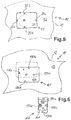
- the controller 27 For the design according to Figs. 3 to 5 and in order to carry out the method shown there, it is generally regarded as necessary for the controller 27 to be present in the transmission translator 21. Finally, it must also control the position lights 25a-d. This could also be done by means of an external control or position detection including the necessary sensors. Then, however, at least a rudimentary control is still required in the transmission translator 21, including a radio module or the like. for communication. If these position lights are not to be arranged on the transmission coaster, there is a possible configuration of the Fig. 6 . There, an inductive cooking appliance 11 of identical design with cover 12 and top side 13 has an optimal position for the transmission coaster 121, shown by dashed lines. The Fig. 6 thus roughly corresponds to the Fig. 4 . In turn, four position sensors 130a-d are contained or arranged in the transmission reducer 121. There are just no position lights included.
- Position lights 130a-d are provided here on an external device in the form of a smartphone 140 with a display 141, and in fact they are indicated by this display 141.
- On the display 141 an operator can see that the transmission reducer 121 is not in the optimal position and also deviates from it by more than a limit distance, so that it has to be shifted backwards and to the left because, for example, the corresponding position lights 130a and 130b light up brighter than the others or flash, as explained at the beginning.
- a controller can either send the corresponding position information to the smartphone 141 in the transmission reducer 121 or in the inductive cooking appliance 11 by radio.
- the smartphone 140 can send this information to the smartphone 140.
- Corresponding information can then be displayed on the display 141, possibly also supported by text information such as "optimum position reached".
- the display 141 can also show the distance by which the transmission reducer 121 must be shifted in a certain direction. This can be done as "Please move 2 cm backwards", that is with text, or only with the direction symbol and the distance to be moved "2 cm”. For this, however, it must be possible not only to be able to detect the reaching of the optimum position in one direction, but also the distance by which the transmission reducer 121 is removed therefrom before the movement.
- identifications or markings or the like be provided, which enable a central or optimal placement of the pot on the transfer coaster 21.
- this surface is only intended for cooking or heating, so that, unlike on the cover 12 including the top 13 itself, a marking does not interfere.
Description
Die Erfindung betrifft ein Verfahren zum induktiven Beheizen eines induktiv beheizbaren Kochgefäßes. Insbesondere geht es bei der Erfindung darum, ein induktiv beheizbares Kochgefäß so beheizen zu können, dass es unabhängig von einer Unterlage erfolgen kann. Des Weiteren betrifft die Erfindung einen Übertragungsuntersetzer, auf den das Kochgefäß zum Beheizen aufgestellt werden kann, und ein induktives Kochgerät zur Durchführung des Verfahrens.The invention relates to a method for inductively heating an inductively heatable cooking vessel. In particular, the invention is about being able to heat an inductively heatable cooking vessel in such a way that it can be done independently of a base. The invention also relates to a transfer coaster on which the cooking vessel can be placed for heating, and an inductive cooking device for carrying out the method.
Aus der
Aus der
Aus der
Aus der
Aus der
Der Erfindung liegt die Aufgabe zugrunde, ein eingangs genanntes Verfahren, einen Übertragungsuntersetzer sowie ein induktives Kochgerät zur Durchführung des Verfahrens zu schaffen, mit denen Probleme und Nachteile des Standes der Technik vermieden werden können und es insbesondere möglich ist, ein praxistaugliches Verfahren zu schaffen, mit dem beim induktiven Beheizen eines Kochgefäßes mittels eines Übertragungsuntersetzers ein optimaler Betrieb bzw. Wirkungsgrad erreicht werden kann.The invention is based on the object of creating a method mentioned at the beginning, a transmission coaster and an inductive cooking device for carrying out the method, with which problems and disadvantages of the prior art can be avoided and in particular it is possible to create a practical method which can be achieved with the inductive heating of a cooking vessel by means of a transfer coaster optimal operation and efficiency.
Gelöst wird diese Aufgabe durch ein Verfahren mit den Merkmalen des Anspruchs 1, durch einen Übertragungsuntersetzer mit den Merkmalen des Anspruchs 11 sowie durch ein induktives Kochgerät zur Durchführung dieses Verfahrens mit den Merkmalen des Anspruchs 13. Vorteilhafte sowie bevorzugte Ausgestaltungen der Erfindung sind Gegenstand der weiteren Ansprüche und werden im Folgenden näher erläutert. Dabei werden manche der Merkmale nur im Zusammenhang mit dem Verfahren, dem Übertragungsuntersetzer oder dem induktiven Kochgerät beschrieben. Sie sollen jedoch unabhängig davon sowohl für das Verfahren als auch für den Übertragungsuntersetzer und für das induktive Kochgerät selbständig und unabhängig voneinander gelten können. Der Wortlaut der Ansprüche wird durch ausdrückliche Bezugnahme zum Inhalt der Beschreibung gemacht.This object is achieved by a method with the features of claim 1, by a transmission coaster with the features of
Das induktive Kochgerät weist mindestens eine Primär-Induktionsspule, eine Abdeckung, die insbesondere flächig ist, über der Primär-Induktionsspule, eine Leistungsversorgung für die Primär-Induktionsspule, und eine Kochgerätsteuerung auf, die mit der Leistungsversorgung verbunden ist. Des Weiteren weist es mindestens einen Übertragungsuntersetzer auf, der insbesondere flach und flächig ist, wobei der Übertragungsuntersetzer unabhängig vom Kochgerät frei bewegbar ist, damit er in einer beliebigen Position auf der Abdeckung oberhalb der Primär-Induktionsspule aufgelegt werden kann. Der Übertragungsuntersetzer weist mindestens einen Schwingkreis mit mindestens einer Schwingkreisspule und mindestens einem Schwingkreiskondensator auf, um induktive Leistung von der Primär-Induktionsspule über den Schwingkreis in das auf den Übertragungsuntersetzer aufgestellte Kochgefäß zu übertragen.The inductive cooking device has at least one primary induction coil, a cover, which is in particular flat, over the primary induction coil, a power supply for the primary induction coil, and a cooking device control that is connected to the power supply. Furthermore, it has at least one transfer coaster, which is particularly flat and planar, the transfer coaster being freely movable independently of the cooking appliance so that it can be placed in any position on the cover above the primary induction coil. The transfer reducer has at least one resonant circuit with at least one resonant circuit coil and at least one resonant circuit capacitor in order to transmit inductive power from the primary induction coil via the resonant circuit into the cooking vessel placed on the transfer reducer.
Erfindungsgemäß ist eine Anzeige für eine Bedienperson vorgesehen um ihr anzuzeigen, ob der Übertragungsuntersetzer optimal oberhalb der Primär-Induktionsspule positioniert ist oder nicht. So kann die Energieübertragung optimiert werden und Streufelder können vermieden werden. Bei dem Verfahren zum induktiven Beheizen eines induktiv beheizbaren Kochgefäßes mittels mindestens einer Induktionsspule des induktiven Kochgeräts werden die folgenden Schritte durchgeführt. Eingangs wird eine Position des Übertragungsuntersetzers relativ zur Primär-Induktionsspule erfasst, was insbesondere hinsichtlich optimaler und/oder zentrischer Position der Schwingkreisspule zur Primär-Induktionsspule erfolgen kann. Im Fall einer Abweichung der Position um mehr als eine Grenz-Entfernung von einer vorgegebenen Optimal-Position können Informationen an die Bedienperson gegeben werden an der Anzeige, in welche Richtung bzw. wie der Übertragungsuntersetzer zu bewegen ist um ihn in die Optimal-Position zu bringen. Die Optimal-Position ist vorteilhaft ein einzelner Punkt oder ein Kreis darum mit geringem Radius, beispielsweise 1 cm bis 5 cm, vorteilhaft bis 2 cm. Der Übertragungsuntersetzer wird im optimalen Fall genau über diesem Punkt oder Kreis aufgesetzt, also zentrisch dazu. Die Grenz-Entfernung kann entweder absolut in cm oder relativ zu einem ungefähren Durchmesser eines aufgestellten Übertragungsuntersetzers angegeben werden, also beispielsweise 5% bis 20% des Durchmessers.According to the invention, a display is provided for an operator to indicate whether or not the transfer reducer is optimally positioned above the primary induction coil. In this way, the energy transfer can be optimized and stray fields can be avoided. In the method for inductively heating an inductively heatable cooking vessel by means of at least one induction coil of the inductive cooking appliance, the following steps are carried out. Initially, a position of the transmission reducer relative to the primary induction coil is detected, which can be done in particular with regard to the optimal and / or central position of the oscillating circuit coil in relation to the primary induction coil. If the position deviates by more than a limit distance from a predetermined optimal position, information can be given to the operator on the display as to the direction or how the transmission reducer is to be moved in order to bring it into the optimal position . The optimal position is advantageously a single point or a circle around it with a small radius, for example 1 cm to 5 cm, advantageously up to 2 cm. In the optimal case, the transfer reducer is placed exactly above this point or circle, i.e. centrally to it. The limit distance can be specified either absolutely in cm or relative to an approximate diameter of an installed transfer coaster, for example 5% to 20% of the diameter.
So kann der Bedienperson mit der Anzeige geholfen werden, den Übertragungsuntersetzer möglichst gut bzw. optimal zu platzieren über der Induktionsspule des induktiven Kochgeräts, auch wenn keinerlei Markierung auf der Oberfläche bzw. Oberseite des induktiven Kochgeräts vorhanden ist. Dadurch kann ein derartiges induktives Kochgerät vorteilhaft eine normale Tischoberfläche aufweisen, beispielsweise aus Holz, Linoleum oder mit einer Kunststoffbeschichtung, die ansonsten wegen thermischer Probleme nicht verwendbar wären oder nur mit der Gefahr, dass ihr Aussehen negativ beeinträchtigt wird durch zu hohe Temperatur aufgrund eines zu heißen aufgestellten Kochgefäßes.The operator can thus be helped with the display to position the transmission coaster as well or optimally as possible over the induction coil of the inductive cooking appliance, even if there is no marking on the surface or top of the inductive cooking appliance. As a result, such an inductive cooking device can advantageously have a normal table surface, for example made of wood, linoleum or with a plastic coating, which otherwise would not be usable due to thermal problems or only with the risk that their appearance is negatively affected by excessively high temperature due to being hot set up cooking vessel.
In Ausgestaltung der Erfindung können die Optimal-Position und/oder die Grenz-Entfernung fest vorgegeben sein, insbesondere werksseitig einprogrammiert sein. Unter Umständen können sie von einer Bedienperson geändert werden. Alternativ können sie unveränderlich einprogrammiert sein.In an embodiment of the invention, the optimal position and / or the limit distance can be permanently specified, in particular programmed in at the factory. Under certain circumstances they can be changed by an operator. Alternatively, they can be programmed to be unchangeable.
Die Grenz-Entfernung kann 1 cm bis 10 cm betragen, vorteilhaft 2 cm bis 5 cm. Alternativ kann sie mindestens 5% des maximalen Durchmessers des Übertragungsuntersetzers betragen, vorzugsweise mindestens 5% bis maximal 100% des maximalen Durchmessers des Übertragungsuntersetzers, insbesondere 10% bis 25%.The limit distance can be 1 cm to 10 cm, advantageously 2 cm to 5 cm. Alternatively, it can be at least 5% of the maximum diameter of the transfer reducer, preferably at least 5% to a maximum of 100% of the maximum diameter of the transfer reducer, in particular 10% to 25%.
Eine möglichst gute Platzierung kann erreicht werden, wenn bevorzugt die Schwingkreisspule des Übertragungsuntersetzers in der Optimal-Position zentrisch zur Primär-Induktionsspule ist. Dann können sogar ihre Größen aufeinander abgestimmt sein, so dass die Übertragung optimal ist.The best possible placement can be achieved if the resonant circuit coil of the transmission reducer is preferably in the optimal position centered on the primary induction coil. Then even their sizes can be coordinated so that the transmission is optimal.
In einer Ausgestaltung der Erfindung ist die Anzeige in den Übertragungsuntersetzer selbst integriert, insbesondere als Leuchtanzeige und/oder mit Leuchtelementen. So kann direkt am Übertragungsuntersetzer erkannt werden, wie er platziert ist bzw. wie er besser platziert werden kann oder muss. Wenn das direkt beim Aufsetzen des Übertragungsuntersetzers erfolgt ist es besonders intuitiv. Die Leuchtanzeige kann dann Leuchtelemente aufweisen, die vorzugsweise an verschiedenen Außenbereichen oder Außenseiten des Übertragungsuntersetzers mit Abstand zueinander angeordnet sind. Dabei ist es möglich, dass Leuchtelemente jeweils an vier gegenüberliegenden Seiten des Übertragungsuntersetzers angeordnet sind, also insgesamt mindestens vier Leuchtelemente. Durch Aktivieren eines Leuchtelements kann dann einer Bedienperson die Information gegeben werden, dass der Übertragungsuntersetzer in einer Richtung entsprechend diesem Leuchtelement von seinem Mittelpunkt hin zu diesem Leuchtelement bewegen werden soll um die Optimal-Position zu erreichen. Wenn die Leuchtelemente nahe oder direkt am Rand des Übertragungsuntersetzers angeordnet sind können sie von einer Bedienperson intuitiv als Richtungsweiser verstanden werden. Es ist dann weiters möglich, durch Blinken bzw. eine Leuchtänderung eines oder mehrerer Leuchtelemente, insbesondere aller Leuchtelemente, das Erreichen dieser Optimal-Position nach Bewegen des Übertragungsuntersetzers anzuzeigen.In one embodiment of the invention, the display is integrated in the transmission coaster itself, in particular as a lighted display and / or with light-emitting elements. In this way it can be seen directly on the transmission coaster how it is placed or how it can or must be better placed. If this is done directly when putting on the transfer coaster, it is particularly intuitive. The luminous display can then have luminous elements, which are preferably arranged at a distance from one another on different outer areas or outer sides of the transmission coaster. It is possible here for lighting elements to be arranged on four opposite sides of the transfer coaster, that is to say at least four lighting elements in total. By activating a light-emitting element, an operator can then be given the information that the transmission reducer is to be moved in a direction corresponding to this light-emitting element from its center point towards this light-emitting element in order to reach the optimum position. If the light-emitting elements are arranged close to or directly on the edge of the transfer coaster, they can be intuitively understood by an operator as a directional indicator. It is then also possible to indicate that this optimum position has been reached after moving the transfer reducer by flashing or changing the light of one or more light elements, in particular all light elements.
Während des Bewegens des Übertragungsuntersetzers zum Erreichen der Optimal-Position kann mindestens ein blinkendes Leuchtelement, in dessen Richtung der Übertragungsuntersetzer bewegt wird, durch zunehmend schnelleres Blinken anzeigen, wenn sich der Übertragungsuntersetzer in dieser Richtung der Optimal-Position nähert. Bei Erreichen der Optimal-Position in dieser Richtung kann dieses Leuchtelement von einem Blinken in ein konstantes Leuchten übergehen. Dann kann eine Bedienperson am konstanten Leuchten ersehen, dass nun ein stabiler und möglichst dauerhafter Zustand erreicht ist.During the movement of the transmission reducer to reach the optimal position, at least one flashing light element, in the direction of which the transmission reducer is being moved, can indicate by increasingly faster flashing when the transmission reducer approaches the optimal position in this direction. When reaching the optimal position in this direction, this light-emitting element can change from blinking to constant lighting. An operator can then see from the constant lighting that a stable and as permanent as possible state has now been reached.
Alternativ kann vorgesehen sein, dass während des Bewegens des Übertragungsuntersetzers zum Erreichen der Optimal-Position mindestens ein blinkendes Leuchtelement, in dessen Richtung der Übertragungsuntersetzer bewegt wird, durch zunehmend helleres Blinken anzeigt, wenn sich der Übertragungsuntersetzer in dieser Richtung der Optimal-Position nähert. Das Blinken ändert sich also wieder, nur dass es diesmal heller wird anstelle schneller. Bei Erreichen der Optimal-Position in dieser Richtung kann dieses Leuchtelement dann von einem Blinken in ein konstantes Leuchten übergehen, was wiederum gut einen möglichst dauerhaften Zustand anzeigen kann.Alternatively, it can be provided that while moving the transmission coaster to reach the optimal position, at least one flashing light element, in the direction of which the transmission coaster is being moved, indicates by increasingly brighter flashing when the transmission coaster is approaching the optimal position in this direction. The blinking changes again, only this time it gets brighter instead of faster. When the optimum position is reached in this direction, this lighting element can then change from blinking to constant lighting, which in turn can indicate a state that is as permanent as possible.
Nochmals alternativ kann vorgesehen sein, dass während des Bewegens des Übertragungsuntersetzers zum Erreichen der Optimal-Position mindestens ein permanent leuchtendes Leuchtelement, in dessen Richtung der Übertragungsuntersetzer bewegt wird, durch zunehmend helleres Leuchten anzeigt, wenn sich der Übertragungsuntersetzer in dieser Richtung der Optimal-Position nähert. Bei Erreichen der Optimal-Position in dieser Richtung kann dieses Leuchtelement von einem konstanten Leuchten in ein Blinken mit der zuletzt eingestellten Helligkeit übergehen, alternativ auch in ein Blinken mit anderer Helligkeit. Dieses Blinken kann zeitlich begrenzt werden auf einige Sekunden, vorzugsweise 2 sec bis 10 sec.Again, alternatively, it can be provided that while the transmission coaster is moving to reach the optimal position, at least one permanently illuminated luminous element, in the direction of which the transmission coaster is being moved, indicates by increasingly brighter lighting when the transmission coaster approaches the optimal position in this direction . When the optimum position is reached in this direction, this light element can change from constant lighting to flashing with the last set brightness, or alternatively also to flashing with a different brightness. This flashing can be limited to a few seconds, preferably 2 seconds to 10 seconds.
In alternativer Ausgestaltung der Erfindung kann die Anzeige an einem separaten und von dem induktiven Kochgerät und dem Übertragungsuntersetzer getrennten externen Gerät angeordnet sein, insbesondere an einem mobilen Endgerät wie einem Mobiltelefon, einem Tablet-Computer oder an einem Fernseher bzw. einem Display. Dabei kann die Anzeige Leuchtelemente als Richtungsmarker aufweisen in vier unterschiedlichen gleichverteilten Richtungen, ähnlich wie zuvor beschrieben wenn die Anzeige am Übertragungsuntersetzer selbst angeordnet ist. Durch Aktivieren eines Leuchtelements kann einer Bedienperson wiederum die Information gegeben werden, den Übertragungsuntersetzer in der Richtung des Richtungsmarkers dieses Leuchtelements zu bewegen um die Optimal-Position zu erreichen. Nur ist in diesem Fall die Anzeige nicht am Übertragungsuntersetzer selbst vorgesehen sondern am externen Gerät. Auch hier kann durch ein Ändern des Verhaltens der Leuchtelemente, wie zuvor beschrieben, vorzugsweise durch Blinken eines oder mehrerer Leuchtelemente, insbesondere aller Leuchtelemente, das Erreichen der Optimal-Position angezeigt werden. Die Richtungsmarker bzw. entsprechenden Leuchtelemente können durch Pfeilform der Bedienperson verdeutlichen, in welche Richtung der Übertragungsuntersetzer bewegt werden soll.In an alternative embodiment of the invention, the display can be arranged on a separate external device separate from the inductive cooking device and the transmission coaster, in particular on a mobile terminal device such as a mobile phone, a tablet computer or on a television or a display. The display can have luminous elements as direction markers in four different evenly distributed directions, similar to that described above when the display is arranged on the transmission coaster itself. By activating a light-emitting element, an operator can in turn be given the information to move the transmission reducer in the direction of the direction marker of this light-emitting element in order to reach the optimum position. Only in this case the display is not provided on the transmission reducer itself but on the external device. Here, too, by changing the behavior of the light elements, as described above, preferably by flashing one or more light elements, in particular all light elements, the reaching of the optimum position can be indicated. The direction markers or corresponding luminous elements can use arrows to indicate to the operator in which direction the transfer reducer is to be moved.
Ähnlich wie zuvor für Anzeige und Leuchtelemente im Übertragungsuntersetzer beschrieben kann mit Anzeige und Leuchtelementen an dem externen Gerät oder auch im induktiven Kochgerät auf die prinzipiell gleiche optische Darstellungsweise angezeigt werden, wie der Übertragungsuntersetzer bewegt werden soll, um optimal und gewünscht platziert zu sein.Similar to what was described above for the display and light elements in the transmission coaster, the display and light elements on the external device or in the inductive cooking device can be used to show in principle the same visual representation as the transmission coaster is to be moved in order to be optimally and appropriately placed.
Während des Bewegens des Übertragungsuntersetzers zum Erreichen der Optimal-Position kann also mindestens ein Leuchtelement, in der Richtung von dessen Richtungsmarker der Übertragungsuntersetzer bewegt wird, durch zunehmend schnelleres oder helleres Blinken anzeigen, wenn sich der Übertragungsuntersetzer in dieser Richtung der Optimal-Position nähert. Bei Erreichen der Optimal-Position in dieser Richtung geht dann dieses Leuchtelement von einem Blinken in ein konstantes Leuchten über. Alternativ kann durch zunehmend helleres Leuchten angezeigt werden, wenn sich der Übertragungsuntersetzer in der richtigen Richtung der Optimal-Position nähert. Eine Entfernung wird dann durch dunkler werdendes Leuchten angezeigt. Es kann auch vorgesehen sein, dass während des Bewegens des Übertragungsuntersetzers zum Erreichen der Optimal-Position mindestens ein Leuchtelement, in der Richtung von dessen Richtungsmarker die Bewegung erfolgt, bei Erreichen der Optimal-Position in dieser Richtung von einem konstanten Leuchten in ein Blinken mit der zuletzt eingestellten Helligkeit übergeht. Dieses Blinken kann von begrenzter Dauer sein, beispielsweise einige Sekunden wie zuvor beschrieben.While moving the transmission coaster to reach the optimal position, at least one light element, in the direction of whose direction marker the transmission coaster is being moved, can indicate by increasingly faster or brighter flashing when the transmission coaster is approaching the optimal position in this direction. When the optimal position is reached in this direction, this light element then changes from blinking to constant lighting. Alternatively, it can be indicated by increasingly brighter lighting when the transmission coaster is approaching the optimal position in the correct direction. A distance is then indicated by a darkening light. It can also be provided that during the movement of the transfer reducer to reach the optimal position, at least one light element, in the direction of whose direction marker the movement takes place, when the optimal position is reached in this direction from constant light to blinking with the last set brightness is ignored. This flashing can be of a limited duration, for example a few seconds as described above.
In Ausgestaltung der Erfindung ist es möglich, dass mehrere ähnliche oder baugleiche oder sogar identische Übertragungsuntersetzer nebeneinander auf die Abdeckung gelegt bzw. positioniert werden. Dies erfolgt bevorzugt jeweils mit der mindestens einen Schwingkreisspule in jedem Übertragungsuntersetzer über einer einzigen oder über mehreren Primär-Induktionsspulen unter der Abdeckung. Dabei können sich die einzelnen Übertragungsuntersetzer jeweils berühren. Es ist in Erweiterung sogar möglich, dass die Übertragungsuntersetzer miteinander elektrisch bzw. steuerungstechnisch gekoppelt werden, beispielsweise drahtlos über Funk. Sie können auch mechanisch verbunden bzw. gekoppelt werden, so dass sie eine fest zusammenhängende Fläche bilden. Ein induktiv beheizbares Kochgefäß mit einer Größe zwischen 70% und 130% der gesamten Fläche der Übertragungsuntersetzer kann dann auf die mehreren Übertragungsuntersetzer aufgestellt werden, um von diesen induktiv beheizt zu werden.In an embodiment of the invention, it is possible that several similar or structurally identical or even identical transfer coasters are placed or positioned next to one another on the cover. This is preferably done in each case with the at least one resonant circuit coil in each transmission reducer above a single or several primary induction coils under the cover. The individual transmission coasters can touch each other. As an extension, it is even possible for the transmission coasters to be coupled to one another electrically or in terms of control technology, for example wirelessly via radio. They can also be mechanically connected or coupled so that they form a firmly connected surface. An inductively heatable cooking vessel with a size between 70% and 130% of the total area of the transfer coasters can then be placed on the several transfer coasters in order to be inductively heated by them.
Es kann vorgesehen sein, dass Leuchtelemente im Übertragungsuntersetzer vom Schwingkreis darin selbst mit Leistung versorgt werden. Dies kann über zwischengeschaltete Leistungswandler oder über eine eigene Induktionsspule mit einem Leuchtelementschwingkreis erfolgen, was an sich dem Fachmann bekannt ist, siehe beispielsweise die
Eine weitere Möglichkeit ist die Verwendung des sogenannten Qi-Standards, der ebenfalls eine induktive Energieübertragung beschreibt und so eine Leistungsversorgung von vorgenannten elektrischen Funktionseinheiten im Übertragungsuntersetzer ermöglicht. Die Energie kann von der Primär-Induktionsspule oder von der Schwingkreisspule kommen.Another possibility is the use of the so-called Qi standard, which also describes inductive energy transmission and thus enables the aforementioned electrical functional units in the transmission reducer to be supplied with power. The energy can come from the primary induction coil or from the resonant circuit coil.
Vorteilhaft ist aber mindestens ein magnetischer oder induktiver Sensor im Übertragungsuntersetzer angeordnet, der zur Erfassung einer Position relativ zu einem Magnet im induktiven Kochgerät oder zu der Primär-Induktionsspule ausgebildet ist, also auch bei der Ermittlung der Optimal-Position helfen kann. Vorzugsweise sind es mindestens zwei solche Sensoren, besonders vorzugsweise vier Sensoren.Advantageously, however, at least one magnetic or inductive sensor is arranged in the transmission reducer, which is designed to detect a position relative to a magnet in the inductive cooking appliance or to the primary induction coil, so it can also help in determining the optimal position. There are preferably at least two such sensors, particularly preferably four sensors.
Alternativ kann mindestens ein magnetischer oder induktiver Sensor im induktiven Kochgerät selbst angeordnet sein, der zur Erfassung einer Position relativ zu einem Magnet im Übertragungsuntersetzer oder zu der Schwingkreisspule darin ausgebildet ist. Auch hier können es vorzugsweise mindestens zwei magnetische oder induktive Sensoren sein, besonders vorzugsweise vier Sensoren.Alternatively, at least one magnetic or inductive sensor can be arranged in the inductive cooking appliance itself, which sensor is designed to detect a position relative to a magnet in the transmission reducer or to the oscillating circuit coil therein. Here, too, there can preferably be at least two magnetic or inductive sensors, particularly preferably four sensors.
In weiterer Ausgestaltung kann mindestens ein Temperatursensor im Übertragungsuntersetzer angeordnet sein, vorzugsweise im oberen Bereich des Übertragungsuntersetzers. Er kann an einer Unterseite einer obersten Schicht oder Abdeckung nach außen anliegen, so dass er die Temperatur der oberen Außenseite bzw. Oberseite erfassen kann, beispielsweise auch eines Bodens eines aufgestellten Topfes. Ein solcher Temperatursensor ist vorteilhaft mit einer vorgenannten Untersetzersteuerung verbunden, die seine Informationen auswerten und ggf. verwerten bzw. umsetzen kann.In a further embodiment, at least one temperature sensor can be arranged in the transfer reducer, preferably in the upper area of the transfer reducer. It can rest on the outside of an underside of a top layer or cover so that it can detect the temperature of the upper outside or top side, for example also of the bottom of a pot that has been set up. Such a temperature sensor is advantageously connected to an aforementioned coaster control, which can evaluate its information and, if necessary, utilize or convert it.
In Weiterbildung der Erfindung kann eine Kommunikation zwischen dem Übertragungsuntersetzer bzw. einer Untersetzersteuerung im Übertragungsuntersetzer einerseits und der Primär-Induktionsspule bzw. der Kochgerätsteuerung andererseits stattfinden. Dadurch kann vor allem die Bestimmung der Position des Übertragungsuntersetzers verbessert werden, vorteilhaft zur Bestimmung der Optimal-Position des Übertragungsuntersetzers über der Primär-Induktionsspule.In a further development of the invention, communication can take place between the transfer reducer or a reducer control in the transfer reducer, on the one hand, and the primary induction coil or the cooking appliance control, on the other hand. As a result, the determination of the position of the transmission reducer can be improved, advantageously for Determination of the optimal position of the transmission reducer above the primary induction coil.
Eine solche Kommunikation zwischen dem Übertragungsuntersetzer und außerhalb davon angeordneten Geräten oder Funktionseinheiten, insbesondere der Primär-Induktionsspule bzw. der Kochgerätsteuerung, kann mittels RFID oder mittels Funk erfolgen. Eine Funkverbindung kann aus der Gruppe WLAN, Bluetooth, BLE oder ZigBee ausgewählt sein. Eine weitere Möglichkeit ist noch eine induktive Kommunikation bzw. Übertragung, insbesondere mit dem Qi-Standard, wie er vom Wireless Power Consortium definiert ist.Such communication between the transmission reducer and devices or functional units arranged outside it, in particular the primary induction coil or the cooking device control, can take place by means of RFID or by radio. A radio connection can be selected from the group WLAN, Bluetooth, BLE or ZigBee. Another possibility is inductive communication or transmission, in particular with the Qi standard as defined by the Wireless Power Consortium.
Der Übertragungsuntersetzer für ein induktives Kochgerät zur Durchführung des vorbeschriebenen Verfahrens selbst kann einen Schwingkreis aufweisen mit mindestens einer Schwingkreisspule und mindestens einem Schwingkreiskondensator zur Übertragung von induktiver Leistung von der Primär-Induktionsspule über den Schwingkreis in das auf den Übertragungsuntersetzer aufgestellte Kochgefäß. Auch diese Übertragung von induktiver Leistung kann ganz allgemein unter Umständen gemäß dem vorgenannten Qi-Standard erfolgen.The transmission coaster for an inductive cooking appliance for performing the above-described method itself can have a resonant circuit with at least one resonant circuit coil and at least one resonant circuit capacitor for transmitting inductive power from the primary induction coil via the resonant circuit into the cooking vessel placed on the transmission coaster. This transmission of inductive power can also take place quite generally in accordance with the aforementioned Qi standard.
An seiner Oberseite besteht der Übertragungsuntersetzer vorteilhaft aus Material mit einer erhöhten Temperaturbeständigkeit, vorteilhaft höher als diejenige, die die Abdeckung des induktiven Kochgeräts aufweisen sollte. Die erhöhte Temperaturbeständigkeit kann mindestens 100°C betragen, vorzugsweise mindestens 150°C und insbesondere mindestens 250°C. Als Material können vorteilhaft Glas, Glaskeramik oder Hartglas verwendet werden. Vorteilhaft ist der Übertragungsuntersetzer als unabhängige und eigenständig handhabbare Baueinheit ausgebildet. Er ist also nicht mittels eines Kabels odgl. mit dem induktiven Kochgerät verbunden. So kann er gut weggeräumt werden wenn er nicht benötigt wird.On its upper side, the transmission coaster is advantageously made of material with an increased temperature resistance, advantageously higher than that which the cover of the inductive cooking appliance should have. The increased temperature resistance can be at least 100.degree. C., preferably at least 150.degree. C. and in particular at least 250.degree. Glass, glass ceramic or hard glass can advantageously be used as the material. The transmission reducer is advantageously designed as an independent structural unit that can be handled independently. So he is not by means of a cable or the like. connected to the inductive cooking device. So it can be easily put away when it is not needed.
In vorteilhafter Ausgestaltung der Erfindung ist unter der wärmebeständigen Schicht an der Oberseite eine Schicht aus thermisch dämmendem Material vorgesehen. Diese kann vollflächig oder zumindest weitgehend vollflächig ausgebildet sein. Dadurch soll eine zu starke Erwärmung innerhalb des Übertragungsuntersetzers vermieden werden.In an advantageous embodiment of the invention, a layer of thermally insulating material is provided under the heat-resistant layer on the top. This can be formed over the entire area or at least largely over the entire area. This is intended to avoid excessive heating within the transfer reducer.
Der Schwingkreis kann in den Übertragungsuntersetzer integriert sein, vorzugsweise mit einer parallel zur Oberseite und/oder Unterseite des Übertragungsuntersetzers verlaufenden Schwingkreisspule. Bevorzugt ist nur eine einzige Schwingkreisspule vorgesehen zur Übertragung der Energie in das darüber befindliche Kochgefäß.The resonant circuit can be integrated into the transmission reducer, preferably with a resonant circuit coil running parallel to the top and / or underside of the transmission reducer. Preferably, only a single resonant circuit coil is provided for transmitting the energy into the cooking vessel located above.
Der Übertragungsuntersetzer kann bevorzugt wasserdicht verschlossen ausgebildet sein oder zumindest so, dass er wasserdicht verschlossen werden kann. Hierfür können beispielsweise Stöpsel oder Klappen vorgesehen sein, ggf. auch am Übertragungsuntersetzer selbst befestigt sein. So kann der Übertragungsuntersetzer auch in einer Geschirrspülmaschine gereinigt werden.The transfer coaster can preferably be designed to be watertight or at least so that it can be closed watertight. For this purpose, for example, plugs or flaps can be provided, possibly also attached to the transfer coaster itself. The transfer coaster can also be cleaned in a dishwasher.
Im Übertragungsuntersetzer können bevorzugt Ferrite oder ferritisches Material vorgesehen sein, insbesondere kann er diese im Inneren enthalten. Sie können auf bekannte Art und Weise zur Beeinflussung, insbesondere Bündelung oder Lenkung, des Magnetfelds von der Primär-Induktionsspule und/oder von der Schwingkreisspule dienen. Dadurch sollen auch Streufelder reduziert werden können.Ferrites or ferritic material can preferably be provided in the transfer coaster, in particular it can contain these inside. They can be used in a known manner to influence, in particular bundling or steering, the magnetic field from the primary induction coil and / or from the resonant circuit coil. This should also be able to reduce stray fields.
In Ausgestaltung der Erfindung kann im Übertragungsuntersetzer eine Kühlvorrichtung für den Übertragungsuntersetzer vorgesehen sein, vorzugsweise ein Lüfter mit Lufteinlass und Luftauslass. Diese Kühlvorrichtung ist vorteilhaft im Übertragungsuntersetzer angeordnet, wobei sie vorzugsweise vom Schwingkreis mit Leistung versorgt werden kann auf zuvor beschriebene Art und Weise.In an embodiment of the invention, a cooling device for the transfer reducer can be provided in the transfer reducer, preferably a fan with an air inlet and air outlet. This cooling device is advantageously arranged in the transmission reducer, and it can preferably be supplied with power from the resonant circuit in the manner described above.
Das induktive Kochgerät, mit dem das vorbeschriebene Verfahren durchgeführt werden kann, vorteilhaft zur Verwendung mit einem vorbeschriebenen Übertragungsuntersetzer, weist mindestens eine Primär-Induktionsspule, eine flächige Abdeckung über der Primär-Induktionsspule, eine Leistungsversorgung für die Primär-Induktionsspule und eine Kochgerätsteuerung auf, die mit der Leistungsversorgung verbunden ist.The inductive cooking appliance, with which the above-described method can be carried out, advantageously for use with a transfer reducing unit as described above, has at least one primary induction coil, a flat cover over the primary induction coil, a power supply for the primary induction coil and a cooking appliance control which is connected to the power supply.
Das induktive Kochgerät kann eine eigene Bedieneinrichtung aufweisen mit Bedienelementen, insbesondere auch mit einer Anzeige, die unter, an oder auf der Abdeckung vorgesehen sein können. Bedienelemente und/oder Anzeige sollten aber reduziert sein bzw. nicht viel Fläche einnehmen, um eben Platz zu sparen und weil sie, abhängig von der Ausbildung der Abdeckung, nicht unbedingt einfach angeordnet werden können. Sie können aber auch unabhängig von der Abdeckung selbst ausgebildet sein, beispielsweise mit Funkverbindung außerhalb des induktiven Kochgeräts angeordnet sein.The inductive cooking appliance can have its own operating device with operating elements, in particular also with a display, which can be provided under, on or on the cover. Control elements and / or displays should, however, be reduced or not take up a lot of space in order to save space and because, depending on the design of the cover, they cannot necessarily be easily arranged. However, they can also be designed independently of the cover itself, for example arranged with a radio link outside the inductive cooking appliance.
Das induktive Kochgerät weist vorteilhaft eine Kochgerätsteuerung auf sowie Kommunikationsmittel für eine Kommunikation nach außerhalb, insbesondere für eine Kommunikation mit einem mobilen Endgerät, beispielsweise einem Tablet-Computer oder einem Smartphone. Dabei können vorteilhaft auch Bedienelemente und/oder Anzeigeelemente des mobilen Endgeräts genutzt werden, wodurch ein sehr guter Doppelnutzen möglich ist. Die Steuerung bzw. ein Steuerverfahren kann beispielsweise als sogenannte App auf dem mobilen Endgerät ablaufen.The inductive cooking appliance advantageously has a cooking appliance control and communication means for external communication, in particular for communication with a mobile terminal, for example a tablet computer or a smartphone. Operating elements and / or display elements of the mobile terminal can also advantageously be used , whereby a very good double benefit is possible. The control or a control method can run as a so-called app on the mobile device, for example.
Diese und weitere Merkmale gehen außer aus den Ansprüchen auch aus der Beschreibung und den Zeichnungen hervor, wobei die einzelnen Merkmale jeweils für sich allein oder zu mehreren in Form von Unterkombination bei einer Ausführungsform der Erfindung und auf anderen Gebieten verwirklicht sein und vorteilhafte sowie für sich schutzfähige Ausführungen darstellen können, für die hier Schutz beansprucht wird. Die Unterteilung der Anmeldung in einzelne Abschnitte sowie Zwischen-Überschriften beschränken die unter diesen gemachten Aussagen nicht in ihrer Allgemeingültigkeit.These and other features emerge from the claims and also from the description and the drawings, the individual features being implemented individually or in combination in the form of subcombinations in one embodiment of the invention and in other areas and being advantageous and protectable per se Can represent designs for which protection is claimed here. The subdivision of the application into individual sections and subheadings does not limit the general validity of the statements made under these.
Weitere Vorteile und Aspekte der Erfindung ergeben sich aus den Ansprüchen und aus der nachfolgenden Beschreibung von bevorzugten Ausführungsbeispielen der Erfindung, die nachfolgend anhand der Figuren erläutert sind. Dabei zeigen:
- Fig. 1
- eine seitliche Schnittdarstellung durch ein erfindungsgemäßes induktives Kochgerät mit einem erfindungsgemäßen Übertragungsuntersetzer darauf,
- Fig. 2
- ein vereinfachtes schematisches Schaltbild zur Darstellung der Energieübertragung,
- Fig. 3
- eine Ansicht von oben auf das induktive Kochgerät mit Übertragungsuntersetzer aus
Fig. 1 samt zu beheizendem Topf in getrennter Darstellung, - Fig. 4
- eine Darstellung, bei der ausgehend von
Fig. 3 der Übertragungsuntersetzer samt Topf auf eine Abdeckung des induktiven Kochgeräts aufgestellt worden ist mit zwei aktivierten Positionsleuchten, - Fig. 5
- den Zustand ausgehend von
Fig. 4 , wenn der Übertragungsuntersetzer korrekt auf die Abdeckung des induktiven Kochgeräts platziert ist und - Fig. 6
- eine Abwandlung der Erfindung, bei der anders als in
Fig. 4 die Anzeige mit den Positionsleuchten an einem Smartphone vorgesehen ist.
- Fig. 1
- a lateral sectional view through an inventive inductive cooking device with a transmission coaster according to the invention thereon,
- Fig. 2
- a simplified schematic circuit diagram to show the energy transfer,
- Fig. 3
- a top view of the inductive cooking device with transmission coaster
Fig. 1 including the pot to be heated in a separate illustration, - Fig. 4
- a representation in which, starting from
Fig. 3 the transfer coaster including the pot has been placed on a cover of the inductive cooking device with two activated position lights, - Fig. 5
- the state based on
Fig. 4 when the transfer coaster is correctly placed on the cover of the inductive cooking appliance and - Fig. 6
- a modification of the invention in which other than in
Fig. 4 the display with the position lights is provided on a smartphone.
In der
An die Unterseite 14 ist eine Primär-Induktionsspule L2 angelegt, insbesondere angedrückt oder angeklebt. Die Primär-Induktionsspule L2 kann kreisrund oder angenähert viereckig bzw. rechteckig oder quadratisch sein. Sie weist mehrere in einer Ebene liegende Windungen auf, wobei dies variiert werden kann. Des Weiteren ist ein Primär-Kondensator C2 vorgesehen, der mit der Primär-Induktionsspule L2 den vorbeschriebenen Schwingkreis bildet. Schließlich können noch Ferrite 19 vorgesehen sein, beispielsweise die Primär-Induktionsspule L2 umgebend und/oder auch darin angeordnet. Dies entspricht aber einem bekannten Aufbau und braucht nicht weiter erläutert zu werden. Die Primär-Induktionsspule L2 ist mit einer entsprechenden Leistungsansteuerung verbunden, wie dies aus dem Stand der Technik bekannt ist, sowie mit einer Kochgerätsteuerung. An der Unterseite 14 der Abdeckung 12 des induktiven Kochgeräts können noch mehrere weitere Primär-Induktionsspulen L2 vorgesehen sein, entweder sehr nahe beieinander um eine durchgehende Fläche zu bilden, oder aber mit Abstand.A primary induction coil L2 is placed on the
Auf die Oberseite 13 der Abdeckung 12 ist ein erfindungsgemäßer Übertragungsuntersetzer aufgestellt, der im Wesentlichen flach ausgebildet ist und beispielsweise 2 cm bis 5 cm hoch sein kann. Der Übertragungsuntersetzer 21 weist ein Gehäuse 22 auf, so dass er vorteilhaft als integrierte Baueinheit ausgebildet ist. In dem Gehäuse 22 befindet sich, vorteilhaft an der Unterseite, eine Schwingkreisspule L3 samt einem zugehörigen Schwingkreiskondensator C3. Diese bilden den eingangs beschriebenen Schwingkreis zum Übertragen von induktiver Leistung von der Primär-Induktionsspule L2 unterhalb davon in einen Topf 36 oberhalb davon.A transfer coaster according to the invention is set up on the
Positionssensoren 30a-d umgeben die Schwingkreisspule L3, deren Verteilung auch aus der
Des Weiteren ist im Übertragungsuntersetzer 21 ein Temperatursensor 29 vorgesehen, der, von Dämmmaterial 32 umgeben, an der Unterseite einer Deckplatte 34 anliegt oder angedrückt ist. Dieser Temperatursensor 29 entspricht einem Temperatursensor auf einer Induktionsheizspule bei einem Induktionskochfeld, der an die Unterseite einer Kochfeldplatte angelegt ist. So kann eine Temperatur der Deckplatte 34 erfasst werden, insbesondere zu ihrem Schutz, möglicherweise auch für eine Heißanzeige, wie sie von Kochfeldern bekannt ist, um eine Bedienperson vor dem Berühren mit der Hand zu warnen. Des Weiteren können mit dem Temperatursensor möglicherweise auch Informationen von einem aufgestellten Topf 36 bezüglich seiner Temperatur abgefragt bzw. erfasst werden.Furthermore, a
In dem Übertragungsuntersetzer 21 ist außerdem noch eine Steuerung 27 als vorgenannte Untersetzersteuerung angeordnet. Diese kann ihre Energie aus dem Schwingkreis im Übertragungsuntersetzer 21 beziehen, beispielsweise durch eine eigene Induktionsspule oder durch direkte Verbindung. Die Steuerung 27 kann die eingangsgenannten Funktionen übernehmen, insbesondere kann sie die Positionssensoren 30a-d auswerten und möglicherweise auch die Positionsleuchten 25a-d ansteuern. Die Steuerung 27 kann auch ein Funkmodul aufweisen um mit einer nicht dargestellten Steuerung des induktiven Kochgeräts 11 und/oder einem externen Gerät kommunizieren, beispielsweise einem Tablet-Computer oder Smartphone als Bediengerät.A
Um die Funktionsbauteile des Übertragungsuntersetzers 21 im Gehäuse 22 zu kühlen, insbesondere die Steuerung 27, ist ein Lüfter 31 am rechten Außenrand vorgesehen. Auch der Lüfter 31 kann seine Energie von dem Schwingkreis im Übertragungsuntersetzer 21 beziehen auf im Prinzip ähnliche Art und Weise wie die Steuerung 27. Der Lüfter 31 weist vorteilhaft Lüftungsschlitze nach außen auf. Diese sind besonders vorteilhaft verschließbar mittels eingebauter Klappen oder mittels eines externen Stopfens odgl.. Dadurch kann der Übertragungsuntersetzer 21 sehr gut und gründlich gereinigt werden, beispielsweise auch in einer Geschirrspülmaschine, wenn er ausreichend abgedichtet ist.In order to cool the functional components of the
Das Dämmmaterial 32 kann beispielsweise Vermiculite oder ein Fasermaterial bzw. Mineralfasermaterial sein. Es schützt die darunter liegenden Funktionseinheiten, insbesondere die Steuerung 27 und die Positionssensoren 30a-d, möglicherweise auch die Positionsleuchten 25a-d, vor zu hoher Temperatur, die ein stark erhitzter Topf 36 nach unten abgeben bzw. abstrahlen kann. Die Deckplatte 34 als Abdeckung des Übertragungsuntersetzers 21 kann aus beliebigem Material bestehen, das mechanisch stabil, temperaturbeständig und durchlässig ist für ein induktives Wechselfeld. Vorteilhaft kann es ein Material wie bei Induktionskochfeldern sein, also Glaskeramik oder Hartglas mit einer Stärke von 1 mm bis 5 mm.The insulating
In der
Mittels einer magnetischen Kopplung M23 sind die Primär-Induktionsspule L2 und die Schwingkreisspule L3 des Übertragungsuntersetzers 21 verbunden, so wird die induktive Energie übertragen. Im Übertragungsuntersetzer 21 ist dann eben noch der Schwingkreiskondensator C3 vorgesehen samt einem Widerstand R3, der die Verluste im Übertragungsuntersetzer 21 darstellt, insbesondere den Kupferwiderstand der Schwingkreisspule L3 sowie den inneren Verlustwiderstand bzw. Serienersatzwiderstand des Schwingkreiskondensators C3. Dieser Schwingkreis sollte möglichst verlustfrei sein, vor allem auch um eine innere Erwärmung des Übertragungsuntersetzers 21 möglichst zu reduzieren oder ganz zu vermeiden.The primary induction coil L2 and the resonant circuit coil L3 of the
Die Schwingkreisspule L3 ist mittels einer magnetischen Kopplung M34 mit dem Boden des Topfes 36 gekoppelt, hier dargestellt durch L4 samt den magnetischen Parametern dieses Topfbodens. Die Widerstände R4 und RL stellen die Verluste im Topfboden dar, insbesondere die Wirbelstromverluste, und zwar sowohl die magnetischen als auch die ohmschen Verluste. Durch sie erwärmt sich der Topfboden überhaupt. Die Kapazität C4 wird sozusagen durch die magnetische Kopplung M34 als Teil des Schwingkreiskondensators C3 übertragen. Somit kann die Primär-Induktionsspule L2 den Boden des Topfes 36 über die beiden magnetischen Kopplungen M23 und M34 induktiv erwärmen, und zwar über die bekannten Wirbelstromverluste im Topf 36.The resonant circuit coil L3 is coupled to the bottom of the
In der
Gut zu erkennen sind am Übertragungsuntersetzer 21 die vier Positionssensoren 30a-d, mit deren Hilfe erkannt werden kann, ob der Übertragungsuntersetzer 21 schon in der strichliert dargestellten vorgesehenen Position auf der Oberseite 13 positioniert ist. Wie aus der
Des Weiteren sind vier Positionsleuchten 25a-d dargestellt, und zwar jeweils am äußeren Rand. Sie weisen Pfeilform nach außen auf und können beliebig zum Leuchten angesteuert werden, wie eingangs erläutert worden ist, also beliebig hell oder auch blinkend.Furthermore, four
In der
Auf eingangs beschriebene Art und Weise können die Positionssensoren 30a-d erkennen, wie sie relativ zur Primär-Induktionsspule L2 angeordnet sind, oder alternativ zu den Ferriten 19 oder zu einem sonstigen Magnet, möglicherweise auch einem Permanentmagnet, unter der Abdeckung 12. Beispielsweise könnte hierzu auch kurz die Primär-Induktionsspule L2 aktiviert werden, und dann die Position dazu bestimmt werden. In der
Die Bedienperson erkennt also, dass sie den Übertragungsuntersetzer 21 nach links und nach hinten verschieben muss. Ist dies erfolgt, so liegt die in
Für die Ausgestaltung gemäß der
Positionsleuchten 130a-d sind hier an einem externen Gerät in Form eines Smartphones 140 mit Display 141 vorgesehen, und zwar werden sie von diesem Display 141 angezeigt. An dem Display 141 kann eine Bedienperson erkennen, dass der Übertragungsuntersetzer 121 nicht in der Optimal-Position ist und auch um mehr als eine Grenz-Entfernung davon abweicht, so dass er nach hinten und nach links verschoben werden muss, weil beispielsweise die entsprechenden Positionsleuchten 130a und 130b heller leuchten als die anderen oder blinken, wie eingangs erläutert worden ist. Dazu kann eine Steuerung entweder im Übertragungsuntersetzer 121 oder im induktiven Kochgerät 11 die entsprechenden Positionsinformationen an das Smartphone 141 senden per Funk. Haben die Positionssensoren 130a-d registriert, dass der Übertragungsuntersetzer 121 nach einem Verschieben dann korrekt positioniert ist, so dass wiederum das Plus-Zeichen innerhalb des Kreis-Zeichens liegen würde, so wird diese Information an das Smartphone 140 gegeben. Am Display 141 kann dann eine entsprechende Information angezeigt werden, möglicherweise noch unterstützt durch Textinformation wie beispielsweise "Optimal-Position erreicht". Es kann in Erweiterung im Display 141 auch zusätzlich zur Richtung angezeigt werden, um welche Entfernung der Übertragungsuntersetzer 121 in eine bestimmte Richtung verschoben werden muss. Dies kann in der Art "Bitte verschieben um 2 cm nach hinten" erfolgen, also mit Text, oder nur mit Richtungssymbol und der zu verschiebenden Entfernung "2 cm". Dazu muss es aber möglich sein, nicht nur das Erreichen der Optimal-Position in einer Richtung erfassen zu können, sondern auch die Entfernung, um die der Übertragungsuntersetzer 121 davon entfernt ist vor dem Verschieben.
Sollte ein eingangs beschriebener Verbund von mehreren Übertragungsuntersetzern gemeinsam platziert werden müssen, um ein einziges darauf abgestelltes Kochgefäß zu beheizen, so können die jeweils am Außenrand liegenden Positionsleuchten aller Übertragungsuntersetzer gemeinsam verwendet werden, und nicht alle Positionsleuchten aller Übertragungsuntersetzer. In dem Fall, dass ein Kochgefäß nämlich schon aufgesetzt worden ist, können diese möglicherweise nicht mehr alle erkannt werden.If a combination of several transmission coasters described at the beginning has to be placed together in order to heat a single cooking vessel placed on it, the position lights of all transmission coasters located on the outer edge can be used are used together, and not all position lights of all transmission coasters. In the event that a cooking vessel has already been put on, it may no longer be possible to recognize all of them.
Eine weitere Möglichkeit zur Anordnung der Übertragungssensoren könnte nicht unter der Deckplatte 34 des Übertragungsuntersetzers 21 sein, sondern an der Seitenkante, möglicherweise etwas ab- bzw. herausstehend. Dann können die Positionsleuchten auch noch erkannt werden, wenn ein Topf aufgestellt worden ist, der in etwa so groß ist wie der Übertragungsuntersetzer selbst.Another possibility for the arrangement of the transmission sensors could not be under the
Auf der Deckplatte 34 wiederum können Kennzeichnungen oder Markierungen odgl. vorgesehen sein, die ein zentrisches bzw. optimales Platzieren des Topfes auf dem Übertragungsuntersetzer 21 ermöglichen. Diese Oberfläche ist schließlich nur zum Kochen bzw. Erhitzen gedacht, so dass, anders als auf der Abdeckung 12 samt Oberseite 13 selbst, eine Markierung nicht stört.On the
Claims (14)
- Method for inductively heating an inductively heatable cooking vessel (36) by means of at least one induction coil (L2) of an induction cooking appliance (11), the induction cooking appliance (11) comprising:- at least one primary induction coil (L2),- a cover (12) over the primary induction coil (L2),- a power supply (VS) for the primary induction coil (L2),- a cooking appliance control connected to the power supply (VS),wherein a display (25a-d, 130a-d) for an operator is provided, in order to show an operator whether or not a transmission coaster (21) is positioned in an optimum position above the primary induction coil (L2),
characterized by
at least one transmission coaster (21, 121) which is freely movable independently of the cooking appliance (11), in order to place it onto any position on the cover (12) above the primary induction coil (L2), wherein the transmission coaster has at least one oscillating circuit including at least one oscillating circuit coil (L3) and at least one oscillating circuit capacitor (C3) for transmission of inductive power from the primary induction coil (L2) via the oscillating circuit into the cooking vessel (36) placed on the transmission coaster (21, 121), wherein the following steps are provided:- detecting a position of the transmission coaster (21, 121) relative to the primary induction coil (L2),- in case of a deviation of the position by more than a limit distance from a predefined optimum position, giving information to the operator on the display (25a-d, 130a-d) in which direction the transmission coaster (21) is to be moved, in order to obtain the optimum position. - Method according to claim 1, characterized in that the optimum position and the limit distance are fixedly predefined.
- Method according to claim 1 or 2, characterized in that the limit distance is at least 5 % of the maximum diameter of the transmission coaster (21, 121), preferably at least 5 % to a maximum of 100 % of the maximum diameter of the transmission coaster.
- Method according to any of the preceding claims, characterized in that the display (25a-d) is integrated in the transmission coaster (21), in particular is an illuminated display and/or includes luminous elements.
- Method according to claim 4, characterized in that the illuminated display includes luminous elements (25a-d) which preferably are disposed on different outer regions or outer sides of the transmission coaster (21) and mutually spaced, wherein in particular in each case four luminous elements are disposed on opposite sides of the transmission coaster, wherein by activating one luminous element (25a-d) an operator is given the information that the transmission coaster (21) has to be moved in the direction from its center point towards this luminous element (25a-d), in order to reach the optimum position, wherein preferably the reaching of the optimum position is shown by flashing of one or more luminous elements, in particular of all of the luminous elements.
- Method according to claim 5, characterized in that during moving of the transmission coaster (21) to reach the optimum position at least one luminous element (25a-d), in the direction of which the transmission coaster is moved, shows by increasingly faster flashing when the transmission coaster approaches the optimum position in this direction, wherein preferably upon reaching the optimum position in this direction this luminous element changes from flashing to a constant glowing.
- Method according to claim 5, characterized in that during moving of the transmission coaster (21) to reach the optimum position at least one luminous element (25a-d), in the direction of which the transmission coaster is moved, shows by increasingly brighter flashing when the transmission coaster (21) approaches the optimum position in this direction, wherein preferably upon reaching the optimum position in this direction this luminous element (25a-d) changes from flashing to a constant glowing.
- Method according to claim 5, characterized in that during moving of the transmission coaster (21) to reach the optimum position at least one luminous element (25a-d), in the direction of which the transmission coaster is moved, shows by increasingly brighter glowing when the transmission coaster approaches the optimum position in this direction, wherein preferably upon reaching the optimum position in this direction this luminous element changes from constant glowing to flashing with the last set brightness.
- Method according to any of claims 1 to 3, characterized in that the display (141) is disposed on a separate external device which is disposed apart from the induction cooking appliance (11) and the transmission coaster (121), in particular on a mobile terminal like a mobile telephone (140), a tablet computer or a television set or a display device, wherein the display (141) includes luminous elements (130a-d) as direction markers in four different uniform directions, wherein by activating one luminous element an operator is given the information that the transmission coaster (121) has to be moved in the direction of the direction marker of this luminous element, in order to reach the optimum position, wherein preferably reaching of the optimum position is shown by flashing of one or more luminous elements (130a-d), in particular of all of the luminous elements.
- Method according to any of the preceding claims, characterized in that communication takes place between the transmission coaster (21, 121) or a coaster control (27) in the transmission coaster and the primary induction coil (L2) or the cooking appliance control, preferably for determining the optimum position of the transmission coaster (21, 121) above the primary induction coil (L2).
- Transmission coaster for an induction cooking appliance (11) for performing the method according to any of the preceding claims, characterized in that the transmission coaster (21, 121):- includes an oscillating circuit including at least one oscillating circuit coil (L3) and at least one oscillating circuit capacitor (C3) for transmission of inductive power from the primary induction coil (L2) via the oscillating circuit into the cooking vessel (36) placed on the transmission coaster (21, 121),- on the upper side (34) thereof is composed of material having a temperature resistance of at least 100 °C,- includes the display (25a-d, 130a-d).
- Transmission coaster according to claim 11, characterized in that the coaster is embodied in an independent and autonomously manageable physical unit.
- Induction cooking appliance (11) for performing the method according to any of the claims 1 to 10, the cooking appliance comprising:- at least one primary induction coil (L2),- a flat cover (12) over the primary induction coil (L2),- a power supply (VS) for the primary induction coil (L2),- a cooking appliance control connected to the power supply (VS),- a transmission coaster (21, 121) according to claim 11 or 12.
- Induction cooking appliance according to claim 13, characterized in that the appliance has a distinct operating device including operating elements, in particular also including a display, preferably below, at or on the cover (12).
Applications Claiming Priority (1)
| Application Number | Priority Date | Filing Date | Title |
|---|---|---|---|
| DE102017220824.4A DE102017220824A1 (en) | 2017-11-22 | 2017-11-22 | Method for inductive heating of an inductively heated cooking vessel, transfer saucer and inductive cooking appliance for carrying out the method |
Publications (2)
| Publication Number | Publication Date |
|---|---|
| EP3490340A1 EP3490340A1 (en) | 2019-05-29 |
| EP3490340B1 true EP3490340B1 (en) | 2020-10-07 |
Family
ID=64362420
Family Applications (1)
| Application Number | Title | Priority Date | Filing Date |
|---|---|---|---|
| EP18207010.2A Active EP3490340B1 (en) | 2017-11-22 | 2018-11-19 | Method for inductively heating an inductively heatable cooking vessel, transmission coaster and induction heating cooker for carrying out the method |
Country Status (2)
| Country | Link |
|---|---|
| EP (1) | EP3490340B1 (en) |
| DE (1) | DE102017220824A1 (en) |
Families Citing this family (5)
| Publication number | Priority date | Publication date | Assignee | Title |
|---|---|---|---|---|
| DE102020000851A1 (en) | 2020-02-11 | 2021-08-12 | Jochen Stephan | Warming device for food |
| KR102147659B1 (en) * | 2020-03-13 | 2020-08-25 | (주)피스월드 | Under induction range system |
| DE102020108194A1 (en) * | 2020-03-25 | 2021-09-30 | Bulthaup Gmbh & Co Kg | System with a furnishing element and a control unit |
| US20230108631A1 (en) * | 2020-05-28 | 2023-04-06 | BSH Hausgeräte GmbH | Underlay arrangement and method for using an underlay arrangement |
| WO2023004389A1 (en) * | 2021-07-21 | 2023-01-26 | Ghsp, Inc. | Display interface for inductive cooktop system |
Family Cites Families (10)
| Publication number | Priority date | Publication date | Assignee | Title |
|---|---|---|---|---|
| DE10159682A1 (en) | 2001-11-30 | 2003-06-26 | Ego Elektro Geraetebau Gmbh | Device for marking an induction coil by lighting |
| DE10315217A1 (en) * | 2003-04-01 | 2004-10-14 | E.G.O. Elektro-Gerätebau GmbH | A cooker ceramic hob unit has indicator units which show whether a cooking pot is displaced or is of unsuitable material |
| ES2366514B1 (en) * | 2009-05-15 | 2012-10-09 | Bsh Electrodomesticos España S.A. | DEVICE FOR PLACEMENT ON AN INDUCTION COOKING FIELD. |
| DE102010028493A1 (en) * | 2010-05-03 | 2011-11-03 | BSH Bosch und Siemens Hausgeräte GmbH | Control unit for a household workstation, household workstation and system from the household workstation and the control panel |
| DE102010028508A1 (en) * | 2010-05-03 | 2011-11-03 | BSH Bosch und Siemens Hausgeräte GmbH | Control panel for a household workstation, household workstation, home workstation and keypad system, and method of operating the system |
| EP2408261B1 (en) * | 2010-07-17 | 2015-09-16 | Electrolux Home Products Corporation N.V. | A wok support for an induction hob |
| DE102010043770A1 (en) * | 2010-11-11 | 2012-05-16 | BSH Bosch und Siemens Hausgeräte GmbH | Household operating device and method for centering a set-top device on a household control gear |
| WO2013103939A1 (en) | 2012-01-08 | 2013-07-11 | Access Business Group International Llc | Inductive cooking system |
| EP3352632A4 (en) * | 2015-09-23 | 2019-05-22 | LG Electronics Inc. | Container support |
| KR102355669B1 (en) * | 2017-09-29 | 2022-01-25 | 엘지전자 주식회사 | Support structure for the object to be heated |
-
2017
- 2017-11-22 DE DE102017220824.4A patent/DE102017220824A1/en not_active Withdrawn
-
2018
- 2018-11-19 EP EP18207010.2A patent/EP3490340B1/en active Active
Non-Patent Citations (1)
| Title |
|---|
| None * |
Also Published As
| Publication number | Publication date |
|---|---|
| EP3490340A1 (en) | 2019-05-29 |
| DE102017220824A1 (en) | 2019-05-23 |
Similar Documents
| Publication | Publication Date | Title |
|---|---|---|
| EP3490340B1 (en) | Method for inductively heating an inductively heatable cooking vessel, transmission coaster and induction heating cooker for carrying out the method | |
| EP1775650B1 (en) | Operating device for an electric appliance | |
| EP1317164B1 (en) | Device for marking an induction coil through lightning | |
| EP2420734A1 (en) | Operating device for a domestic appliance with an energy supply device and domestic appliance for preparing food with such an operating device | |
| DE112015007026T5 (en) | Heating cooker system, induction cooker and electrical appliance | |
| WO2006072388A1 (en) | Cooking hob comprising a light, and method for illuminating a cooking hob | |
| EP2706816B1 (en) | Operating method for a cooking hob and cooking hob | |
| DE102005040206A1 (en) | Domestic cooking appliance has an operating control system into which a portable computer may be connected which has a barcode reader to convey specific cooking data to the appliance | |
| EP3518618B1 (en) | Cooking hob with at least two heating zones | |
| EP0853444A2 (en) | Cooking system with an electric cooking-plate, transferring heat by conduction | |
| EP2453715B1 (en) | Household operating device and method for centring an attachment to a household operating device | |
| DE102005049995A1 (en) | Operating device for preferably electrical heating appliance has additional switching facility provided on rotary controller and provides signal transmission of switching action to control unit below face of electrical appliance | |
| DE102009001934B4 (en) | Cooking appliance with at least one hob | |
| EP1217873B1 (en) | Temperature of cooking vessels sensing method and device | |
| DE102017203080A1 (en) | Kitchen appliance with lighting device and method for operating a lighting device of a kitchen appliance | |
| EP2256417A2 (en) | Gas hob with a hotplate and at least one cooking surface | |
| DE102010039559B4 (en) | Operating device for a domestic appliance with an energy supply device and domestic appliance for preparing food with such an operating device | |
| EP3490339B1 (en) | Induction cooking hob and pot detection sensor for an induction cooking hob | |
| DE102008054909A1 (en) | Method for operating an electric food preparation device | |
| EP2420735B1 (en) | Operating device for a domestic appliance with an energy supply device and domestic appliance for preparing food with such an operating device | |
| EP1841289B1 (en) | Device for preparing and/or keeping warm cooked foods | |
| DE102009055147A1 (en) | Power transmission unit for household cooking appliance, has display device comprising information regions whose spatial arrangement correlates to spatial arrangement of corresponding power transmitting parts | |
| EP3352529B1 (en) | Hotplate | |
| EP2680246B1 (en) | Domestic appliance | |
| DE102018202255B4 (en) | Cooktop and method of operating a cooktop |
Legal Events
| Date | Code | Title | Description |
|---|---|---|---|
| PUAI | Public reference made under article 153(3) epc to a published international application that has entered the european phase |
Free format text: ORIGINAL CODE: 0009012 |
|
| STAA | Information on the status of an ep patent application or granted ep patent |
Free format text: STATUS: THE APPLICATION HAS BEEN PUBLISHED |
|
| AK | Designated contracting states |
Kind code of ref document: A1 Designated state(s): AL AT BE BG CH CY CZ DE DK EE ES FI FR GB GR HR HU IE IS IT LI LT LU LV MC MK MT NL NO PL PT RO RS SE SI SK SM TR |
|
| AX | Request for extension of the european patent |
Extension state: BA ME |
|
| STAA | Information on the status of an ep patent application or granted ep patent |
Free format text: STATUS: REQUEST FOR EXAMINATION WAS MADE |
|
| 17P | Request for examination filed |
Effective date: 20191126 |
|
| RBV | Designated contracting states (corrected) |
Designated state(s): AL AT BE BG CH CY CZ DE DK EE ES FI FR GB GR HR HU IE IS IT LI LT LU LV MC MK MT NL NO PL PT RO RS SE SI SK SM TR |
|
| GRAP | Despatch of communication of intention to grant a patent |
Free format text: ORIGINAL CODE: EPIDOSNIGR1 |
|
| STAA | Information on the status of an ep patent application or granted ep patent |
Free format text: STATUS: GRANT OF PATENT IS INTENDED |
|
| INTG | Intention to grant announced |
Effective date: 20200506 |
|
| RIC1 | Information provided on ipc code assigned before grant |
Ipc: H05B 6/12 20060101AFI20200420BHEP |
|
| GRAS | Grant fee paid |
Free format text: ORIGINAL CODE: EPIDOSNIGR3 |
|
| GRAA | (expected) grant |
Free format text: ORIGINAL CODE: 0009210 |
|
| STAA | Information on the status of an ep patent application or granted ep patent |
Free format text: STATUS: THE PATENT HAS BEEN GRANTED |
|
| AK | Designated contracting states |
Kind code of ref document: B1 Designated state(s): AL AT BE BG CH CY CZ DE DK EE ES FI FR GB GR HR HU IE IS IT LI LT LU LV MC MK MT NL NO PL PT RO RS SE SI SK SM TR |
|
| REG | Reference to a national code |
Ref country code: GB Ref legal event code: FG4D Free format text: NOT ENGLISH |
|
| REG | Reference to a national code |
Ref country code: CH Ref legal event code: EP Ref country code: AT Ref legal event code: REF Ref document number: 1322605 Country of ref document: AT Kind code of ref document: T Effective date: 20201015 |
|
| REG | Reference to a national code |
Ref country code: DE Ref legal event code: R096 Ref document number: 502018002678 Country of ref document: DE |
|
| REG | Reference to a national code |
Ref country code: IE Ref legal event code: FG4D Free format text: LANGUAGE OF EP DOCUMENT: GERMAN |
|
| REG | Reference to a national code |
Ref country code: NL Ref legal event code: MP Effective date: 20201007 |
|
| PG25 | Lapsed in a contracting state [announced via postgrant information from national office to epo] |
Ref country code: PT Free format text: LAPSE BECAUSE OF FAILURE TO SUBMIT A TRANSLATION OF THE DESCRIPTION OR TO PAY THE FEE WITHIN THE PRESCRIBED TIME-LIMIT Effective date: 20210208 Ref country code: RS Free format text: LAPSE BECAUSE OF FAILURE TO SUBMIT A TRANSLATION OF THE DESCRIPTION OR TO PAY THE FEE WITHIN THE PRESCRIBED TIME-LIMIT Effective date: 20201007 Ref country code: FI Free format text: LAPSE BECAUSE OF FAILURE TO SUBMIT A TRANSLATION OF THE DESCRIPTION OR TO PAY THE FEE WITHIN THE PRESCRIBED TIME-LIMIT Effective date: 20201007 Ref country code: NO Free format text: LAPSE BECAUSE OF FAILURE TO SUBMIT A TRANSLATION OF THE DESCRIPTION OR TO PAY THE FEE WITHIN THE PRESCRIBED TIME-LIMIT Effective date: 20210107 Ref country code: GR Free format text: LAPSE BECAUSE OF FAILURE TO SUBMIT A TRANSLATION OF THE DESCRIPTION OR TO PAY THE FEE WITHIN THE PRESCRIBED TIME-LIMIT Effective date: 20210108 |
|
| REG | Reference to a national code |
Ref country code: LT Ref legal event code: MG4D |
|
| PG25 | Lapsed in a contracting state [announced via postgrant information from national office to epo] |
Ref country code: SE Free format text: LAPSE BECAUSE OF FAILURE TO SUBMIT A TRANSLATION OF THE DESCRIPTION OR TO PAY THE FEE WITHIN THE PRESCRIBED TIME-LIMIT Effective date: 20201007 Ref country code: IS Free format text: LAPSE BECAUSE OF FAILURE TO SUBMIT A TRANSLATION OF THE DESCRIPTION OR TO PAY THE FEE WITHIN THE PRESCRIBED TIME-LIMIT Effective date: 20210207 Ref country code: LV Free format text: LAPSE BECAUSE OF FAILURE TO SUBMIT A TRANSLATION OF THE DESCRIPTION OR TO PAY THE FEE WITHIN THE PRESCRIBED TIME-LIMIT Effective date: 20201007 Ref country code: PL Free format text: LAPSE BECAUSE OF FAILURE TO SUBMIT A TRANSLATION OF THE DESCRIPTION OR TO PAY THE FEE WITHIN THE PRESCRIBED TIME-LIMIT Effective date: 20201007 Ref country code: BG Free format text: LAPSE BECAUSE OF FAILURE TO SUBMIT A TRANSLATION OF THE DESCRIPTION OR TO PAY THE FEE WITHIN THE PRESCRIBED TIME-LIMIT Effective date: 20210107 Ref country code: ES Free format text: LAPSE BECAUSE OF FAILURE TO SUBMIT A TRANSLATION OF THE DESCRIPTION OR TO PAY THE FEE WITHIN THE PRESCRIBED TIME-LIMIT Effective date: 20201007 |
|
| PG25 | Lapsed in a contracting state [announced via postgrant information from national office to epo] |
Ref country code: HR Free format text: LAPSE BECAUSE OF FAILURE TO SUBMIT A TRANSLATION OF THE DESCRIPTION OR TO PAY THE FEE WITHIN THE PRESCRIBED TIME-LIMIT Effective date: 20201007 Ref country code: NL Free format text: LAPSE BECAUSE OF FAILURE TO SUBMIT A TRANSLATION OF THE DESCRIPTION OR TO PAY THE FEE WITHIN THE PRESCRIBED TIME-LIMIT Effective date: 20201007 |
|
| REG | Reference to a national code |
Ref country code: DE Ref legal event code: R097 Ref document number: 502018002678 Country of ref document: DE |
|
| PG25 | Lapsed in a contracting state [announced via postgrant information from national office to epo] |
Ref country code: RO Free format text: LAPSE BECAUSE OF FAILURE TO SUBMIT A TRANSLATION OF THE DESCRIPTION OR TO PAY THE FEE WITHIN THE PRESCRIBED TIME-LIMIT Effective date: 20201007 Ref country code: MC Free format text: LAPSE BECAUSE OF FAILURE TO SUBMIT A TRANSLATION OF THE DESCRIPTION OR TO PAY THE FEE WITHIN THE PRESCRIBED TIME-LIMIT Effective date: 20201007 Ref country code: LU Free format text: LAPSE BECAUSE OF NON-PAYMENT OF DUE FEES Effective date: 20201119 Ref country code: LT Free format text: LAPSE BECAUSE OF FAILURE TO SUBMIT A TRANSLATION OF THE DESCRIPTION OR TO PAY THE FEE WITHIN THE PRESCRIBED TIME-LIMIT Effective date: 20201007 Ref country code: CZ Free format text: LAPSE BECAUSE OF FAILURE TO SUBMIT A TRANSLATION OF THE DESCRIPTION OR TO PAY THE FEE WITHIN THE PRESCRIBED TIME-LIMIT Effective date: 20201007 Ref country code: EE Free format text: LAPSE BECAUSE OF FAILURE TO SUBMIT A TRANSLATION OF THE DESCRIPTION OR TO PAY THE FEE WITHIN THE PRESCRIBED TIME-LIMIT Effective date: 20201007 Ref country code: SK Free format text: LAPSE BECAUSE OF FAILURE TO SUBMIT A TRANSLATION OF THE DESCRIPTION OR TO PAY THE FEE WITHIN THE PRESCRIBED TIME-LIMIT Effective date: 20201007 Ref country code: SM Free format text: LAPSE BECAUSE OF FAILURE TO SUBMIT A TRANSLATION OF THE DESCRIPTION OR TO PAY THE FEE WITHIN THE PRESCRIBED TIME-LIMIT Effective date: 20201007 |
|
| REG | Reference to a national code |
Ref country code: BE Ref legal event code: MM Effective date: 20201130 |
|
| PLBE | No opposition filed within time limit |
Free format text: ORIGINAL CODE: 0009261 |
|
| STAA | Information on the status of an ep patent application or granted ep patent |
Free format text: STATUS: NO OPPOSITION FILED WITHIN TIME LIMIT |
|
| PG25 | Lapsed in a contracting state [announced via postgrant information from national office to epo] |
Ref country code: DK Free format text: LAPSE BECAUSE OF FAILURE TO SUBMIT A TRANSLATION OF THE DESCRIPTION OR TO PAY THE FEE WITHIN THE PRESCRIBED TIME-LIMIT Effective date: 20201007 |
|
| 26N | No opposition filed |
Effective date: 20210708 |
|
| PG25 | Lapsed in a contracting state [announced via postgrant information from national office to epo] |
Ref country code: IE Free format text: LAPSE BECAUSE OF NON-PAYMENT OF DUE FEES Effective date: 20201119 Ref country code: IT Free format text: LAPSE BECAUSE OF FAILURE TO SUBMIT A TRANSLATION OF THE DESCRIPTION OR TO PAY THE FEE WITHIN THE PRESCRIBED TIME-LIMIT Effective date: 20201007 Ref country code: AL Free format text: LAPSE BECAUSE OF FAILURE TO SUBMIT A TRANSLATION OF THE DESCRIPTION OR TO PAY THE FEE WITHIN THE PRESCRIBED TIME-LIMIT Effective date: 20201007 |
|
| PG25 | Lapsed in a contracting state [announced via postgrant information from national office to epo] |
Ref country code: SI Free format text: LAPSE BECAUSE OF FAILURE TO SUBMIT A TRANSLATION OF THE DESCRIPTION OR TO PAY THE FEE WITHIN THE PRESCRIBED TIME-LIMIT Effective date: 20201007 |
|
| PG25 | Lapsed in a contracting state [announced via postgrant information from national office to epo] |
Ref country code: IS Free format text: LAPSE BECAUSE OF FAILURE TO SUBMIT A TRANSLATION OF THE DESCRIPTION OR TO PAY THE FEE WITHIN THE PRESCRIBED TIME-LIMIT Effective date: 20210207 Ref country code: TR Free format text: LAPSE BECAUSE OF FAILURE TO SUBMIT A TRANSLATION OF THE DESCRIPTION OR TO PAY THE FEE WITHIN THE PRESCRIBED TIME-LIMIT Effective date: 20201007 Ref country code: MT Free format text: LAPSE BECAUSE OF FAILURE TO SUBMIT A TRANSLATION OF THE DESCRIPTION OR TO PAY THE FEE WITHIN THE PRESCRIBED TIME-LIMIT Effective date: 20201007 Ref country code: CY Free format text: LAPSE BECAUSE OF FAILURE TO SUBMIT A TRANSLATION OF THE DESCRIPTION OR TO PAY THE FEE WITHIN THE PRESCRIBED TIME-LIMIT Effective date: 20201007 |
|
| PG25 | Lapsed in a contracting state [announced via postgrant information from national office to epo] |
Ref country code: MK Free format text: LAPSE BECAUSE OF FAILURE TO SUBMIT A TRANSLATION OF THE DESCRIPTION OR TO PAY THE FEE WITHIN THE PRESCRIBED TIME-LIMIT Effective date: 20201007 |
|
| REG | Reference to a national code |
Ref country code: CH Ref legal event code: PL |
|
| PG25 | Lapsed in a contracting state [announced via postgrant information from national office to epo] |
Ref country code: BE Free format text: LAPSE BECAUSE OF NON-PAYMENT OF DUE FEES Effective date: 20201130 |
|
| GBPC | Gb: european patent ceased through non-payment of renewal fee |
Effective date: 20221119 |
|
| PG25 | Lapsed in a contracting state [announced via postgrant information from national office to epo] |
Ref country code: LI Free format text: LAPSE BECAUSE OF NON-PAYMENT OF DUE FEES Effective date: 20220630 Ref country code: CH Free format text: LAPSE BECAUSE OF NON-PAYMENT OF DUE FEES Effective date: 20220630 |
|
| PG25 | Lapsed in a contracting state [announced via postgrant information from national office to epo] |
Ref country code: GB Free format text: LAPSE BECAUSE OF NON-PAYMENT OF DUE FEES Effective date: 20221119 |
|
| PGFP | Annual fee paid to national office [announced via postgrant information from national office to epo] |
Ref country code: FR Payment date: 20231124 Year of fee payment: 6 Ref country code: DE Payment date: 20231123 Year of fee payment: 6 |