EP3352477A1 - Sound generation device and production method therefor - Google Patents
Sound generation device and production method therefor Download PDFInfo
- Publication number
- EP3352477A1 EP3352477A1 EP16846060.8A EP16846060A EP3352477A1 EP 3352477 A1 EP3352477 A1 EP 3352477A1 EP 16846060 A EP16846060 A EP 16846060A EP 3352477 A1 EP3352477 A1 EP 3352477A1
- Authority
- EP
- European Patent Office
- Prior art keywords
- armature
- end part
- vibration
- fixed
- base end
- Prior art date
- Legal status (The legal status is an assumption and is not a legal conclusion. Google has not performed a legal analysis and makes no representation as to the accuracy of the status listed.)
- Withdrawn
Links
Images




Classifications
-
- H—ELECTRICITY
- H04—ELECTRIC COMMUNICATION TECHNIQUE
- H04R—LOUDSPEAKERS, MICROPHONES, GRAMOPHONE PICK-UPS OR LIKE ACOUSTIC ELECTROMECHANICAL TRANSDUCERS; ELECTRIC HEARING AIDS; PUBLIC ADDRESS SYSTEMS
- H04R9/00—Transducers of moving-coil, moving-strip, or moving-wire type
- H04R9/06—Loudspeakers
-
- H—ELECTRICITY
- H04—ELECTRIC COMMUNICATION TECHNIQUE
- H04R—LOUDSPEAKERS, MICROPHONES, GRAMOPHONE PICK-UPS OR LIKE ACOUSTIC ELECTROMECHANICAL TRANSDUCERS; ELECTRIC HEARING AIDS; PUBLIC ADDRESS SYSTEMS
- H04R11/00—Transducers of moving-armature or moving-core type
- H04R11/02—Loudspeakers
-
- B—PERFORMING OPERATIONS; TRANSPORTING
- B23—MACHINE TOOLS; METAL-WORKING NOT OTHERWISE PROVIDED FOR
- B23P—METAL-WORKING NOT OTHERWISE PROVIDED FOR; COMBINED OPERATIONS; UNIVERSAL MACHINE TOOLS
- B23P19/00—Machines for simply fitting together or separating metal parts or objects, or metal and non-metal parts, whether or not involving some deformation; Tools or devices therefor so far as not provided for in other classes
- B23P19/04—Machines for simply fitting together or separating metal parts or objects, or metal and non-metal parts, whether or not involving some deformation; Tools or devices therefor so far as not provided for in other classes for assembling or disassembling parts
-
- H—ELECTRICITY
- H04—ELECTRIC COMMUNICATION TECHNIQUE
- H04R—LOUDSPEAKERS, MICROPHONES, GRAMOPHONE PICK-UPS OR LIKE ACOUSTIC ELECTROMECHANICAL TRANSDUCERS; ELECTRIC HEARING AIDS; PUBLIC ADDRESS SYSTEMS
- H04R31/00—Apparatus or processes specially adapted for the manufacture of transducers or diaphragms therefor
-
- H—ELECTRICITY
- H04—ELECTRIC COMMUNICATION TECHNIQUE
- H04R—LOUDSPEAKERS, MICROPHONES, GRAMOPHONE PICK-UPS OR LIKE ACOUSTIC ELECTROMECHANICAL TRANSDUCERS; ELECTRIC HEARING AIDS; PUBLIC ADDRESS SYSTEMS
- H04R31/00—Apparatus or processes specially adapted for the manufacture of transducers or diaphragms therefor
- H04R31/003—Apparatus or processes specially adapted for the manufacture of transducers or diaphragms therefor for diaphragms or their outer suspension
-
- H—ELECTRICITY
- H04—ELECTRIC COMMUNICATION TECHNIQUE
- H04R—LOUDSPEAKERS, MICROPHONES, GRAMOPHONE PICK-UPS OR LIKE ACOUSTIC ELECTROMECHANICAL TRANSDUCERS; ELECTRIC HEARING AIDS; PUBLIC ADDRESS SYSTEMS
- H04R31/00—Apparatus or processes specially adapted for the manufacture of transducers or diaphragms therefor
- H04R31/006—Interconnection of transducer parts
-
- H—ELECTRICITY
- H04—ELECTRIC COMMUNICATION TECHNIQUE
- H04R—LOUDSPEAKERS, MICROPHONES, GRAMOPHONE PICK-UPS OR LIKE ACOUSTIC ELECTROMECHANICAL TRANSDUCERS; ELECTRIC HEARING AIDS; PUBLIC ADDRESS SYSTEMS
- H04R9/00—Transducers of moving-coil, moving-strip, or moving-wire type
- H04R9/02—Details
- H04R9/025—Magnetic circuit
-
- H—ELECTRICITY
- H04—ELECTRIC COMMUNICATION TECHNIQUE
- H04R—LOUDSPEAKERS, MICROPHONES, GRAMOPHONE PICK-UPS OR LIKE ACOUSTIC ELECTROMECHANICAL TRANSDUCERS; ELECTRIC HEARING AIDS; PUBLIC ADDRESS SYSTEMS
- H04R2400/00—Loudspeakers
- H04R2400/11—Aspects regarding the frame of loudspeaker transducers
Definitions
- the present invention relates to a sound generation device provided with an armature that extends parallel to a vibration plate and vibration of the armature is transmitted to the vibration plate, and to a production method therefor.
- Patent Document 1 describes an invention related to a sound generation device (sound transducer).
- This sound generation device has a holding frame fixed inside a case body.
- the holding frame has an opening that is covered by a resin film, and a vibration plate formed by a thin metal plate is adhered on the resin film.
- An armature that is formed by a magnetic material is accommodated inside the case body.
- the armature has a vibration part and a fixed part that are integrally formed, and the fixed part is positioned and fixed to the holding frame.
- a coil mounting part is formed on the armature, a coil is fixed to this coil mounting part, and the vibration part is arranged within a space part of at a coil winding center.
- a pair of fixing pieces is integrally formed on the armature, and the yoke is fixed in a state sandwiched between the fixing pieces.
- the yoke is formed by a first member that is bent to a U-shape, and a plate-shaped second member that is fixed in a state across sidewalls of the first member.
- One magnet is fixed to a bottom inner surface of the first member, and another magnet is fixed to an inner surface of the second member.
- the vibration part of the armature is positioned between the upper and lower magnets that oppose each other. A free end part of the vibration part and the vibration plate are connected by a beam part.
- the armature is magnetized by a voice current applied to the coil, and the vibration part vibrates due to this magnetization and a magnetic field of the magnet. This vibration is transmitted to the vibration plate via the beam part, and sound is generated by the vibration of the vibration plate.
- Patent Document 1 Japanese Laid-Open Patent Publication No. 2012-4850
- the fixed part of the armature is fixed to the holding frame, the coil mounting part and the fixing pieces are formed on this armature, the coil is fixed to the coil mounting part, and the yoke is fixed in the state sandwiched between the fixing pieces.
- the coil and the yoke are mutually positioned and fixed on the armature, before fixing the armature on the holding frame, and for this reason, it is difficult to perform an efficient assembling operation using a robot to successively assemble each of the parts on the holding frame.
- the yoke described in Patent Document 1 is formed by the first member that is bent to the U-shape, and the plate-shaped second member that is fixed in the state across the sidewalls of the first member. According to this structure, when assembling the yoke, it is necessary to insert the second member between the sidewalls of the first member in a state in which the opposing sidewalls of the first member are opened in a direction so as to separate from each other, and thereafter deform the sidewalls in a direction so as to close upon each other, before fixing both end surfaces of the second member to inner surfaces of the sidewalls. For this reason, the assembling operation is complex, and it is also difficult to perform an automated assembling operation.
- the present invention solves the above described problem that is conventionally encountered, and one object of the present invention is to provide a sound generation device and a production method therefor, according to which relative positions of a magnet and an armature can be determined with a high accuracy with reference to a mounting surface of a frame.
- Another object of the present invention is to provide a sound generation device and a production method therefor, according to which each part can be successively assembled with respect to a frame, and an assembling operation can be automated.
- the present invention relates to a sound generation device comprising a vibration plate, an armature extending parallel to the vibration plate, a coil having a conductor wire wound around the armature, a magnetic field generation unit opposing the armature, and a transmitting body that transmits vibration of the armature to the vibration plate, characterized in that:
- the sound generation device may be configured so that the magnetic field generation unit has an upper yoke and a lower yoke, and at least 2 side yokes arranged between the upper yoke and the lower yoke, the upper yoke and the lower yoke are plate-shaped, and plate surfaces thereof are mutually parallel, the side plates are plate-shaped, and plate surfaces thereof are perpendicular to the plate surfaces of the upper yoke and the lower yoke, respectively, wherein the plate surfaces of the side yokes are mutually parallel and arranged with a gap therebetween, and both end surfaces of the side yokes are fixed to the plate surfaces of the upper yoke and the lower yoke, respectively, the magnets are fixed on the mutually opposing plate surfaces of the upper yoke and the lower yoke, respectively, and the armature is arranged inside the gap between the magnets opposing each other in up-and-down direction, and an upper surface of the upper yoke forms
- the sound generation device may be configured so that the armature has a vibration part, a tip end part connected to the transmitting body, and a base end part connected to the vibration part via a folded part, wherein the vibration part and the base end part extend in parallel, and the base end part is fixed to the mounting surface.
- the sound generation device may be configured so that the armature has a plate-shape including a vibration part, a tip end part connected to the transmitting body, and a base end part connecting from the vibration part, and a support member is fixed to the mounting surface, the support member has a parallel support surface formed in parallel to the mounting surface, and the base end part is fixed to the parallel support surface.
- the sound generation device may be configured so that the armature has a vibration part, a tip end part connected to the transmitting body, and a base end part bent in a perpendicular direction from the vibration part, and a support member is fixed to the mounting surface, the support member has a perpendicular support surface formed perpendicularly to the mounting surface, and the base end part is fixed to the perpendicular support surface.
- the sound generation device according to the present invention may preferably be configured so that the frame is formed by a magnetic material.
- the sound generation device according to the present invention may preferably be configured so that the frame and the support member are formed by a magnetic material.
- the present invention relates to a production method for producing a sound generation device that includes a vibration plate, an armature extending parallel to the vibration plate, a coil having a conductor wire wound around the armature, a magnetic field generation unit opposing the armature, and a transmitting body that transmits vibration of the armature to the vibration plate, characterized in that there are provided:
- the production method for producing the sound generation device according to the present invention may be configured so that the armature has a vibration part, the tip end part connected to the transmitting body, and the base end part connected to the vibration part via a folded part, wherein the vibration part and the base end part extend in parallel, and the base end part is fixed to the mounting surface.
- the production method for producing the sound generation device may be configured so that the armature has a plate-shape including a vibration part, the tip end part connected to the transmitting body, and the base end part connecting from the vibration part, and a support member is fixed to the mounting surface, the support member has a parallel support surface formed in parallel to the mounting surface, and the base end part is fixed to the parallel support surface.
- the production method for producing the sound generation device may be configured so that the armature has a vibration part, the tip end part connected to the transmitting body, and the base end part bent in a perpendicular direction from the vibration part, and a support member is fixed to the mounting surface, the support member has a perpendicular support surface formed perpendicularly to the mounting surface, and the base end part is fixed to the perpendicular support surface after butting the base end part against the perpendicular support surface and adjusting a distance between the mounting surface and the armature.
- the production method for producing the sound generation device according to the present invention may preferably be configured so that a cavity is formed in the tip end part of the armature, and the tip end part and the armature are fixed after moving the armature in parallel to the vibration plate and guiding the transmitting body into the cavity.
- the magnetic field generation unit is fixed with reference to the mounting surface formed on the frame, and the armature is fixed with reference to the mounting surface.
- an assembling method of the sound generation device of the present invention can perform the assembling operation to assemble each part on the frame with a high accuracy, and the assembling operation can be automated.
- FIG. 1 through FIG. 3 illustrate a sound generation device 1 in a first embodiment of the present invention.
- the sound generation device 1 has a casing 2.
- the casing 2 is formed by a lower casing 3 and an upper casing 4.
- the lower casing 3 and the upper casing 4 are made of a synthetic resin or a metal that is a nonmagnetic material, by press molding or die-casting.
- the lower casing 3 has a bottom part 3a, a sidewall part 3b surrounding 4 sides, and an open end 3c at an upper end of the sidewall part 3b.
- the upper casing 4 has a ceiling part 4a, a sidewall part 4b surrounding 4 sides, and an open end 4c at a lower end of the sidewall part 4b.
- An internal space of the lower casing 3 is larger than an internal space of the upper casing 4, and the upper casing 4 functions as a lid body for the lower casing 3.
- a frame 5 is sandwiched between the open end 3c of the lower casing 3 and the open end 4c of the upper casing 4.
- a positioning mechanism using male-female fitting is formed between the open end 3c of the lower casing 3 and the frame 5
- a positioning mechanism using male-female fitting is formed between the open end 4c of the upper casing 4 and the frame 5.
- the lower casing 3, the upper casing 4, and the frame 5 are positioned by these positioning mechanisms, and the lower casing 3, the upper casing 4, and the frame 5 are fixed to each other by an adhesive agent or the like.
- the frame 5 is formed by a plate member having a uniform thickness in a Z-direction, and a lower plane in FIG. 2 forms a driving end mounting surface 5a, and an upper plane in FIG. 2 forms a vibrating end mounting surface 5b.
- An opening 5c at a central part of the frame 5 is formed to penetrate the frame 5 in an up-and-down direction.
- a vibration plate 11 and a flexible sheet 12 are mounted on the vibrating end mounting surface 5b of the frame 5.
- the vibration plate 11 is formed by a thin metal material such as aluminum or the like, and is press-molded with a rib to increase bending strength, if necessary.
- the flexible sheet 12 is resiliently deformed more easily than the vibration plate 11, and is formed by a resin sheet (resin film) made of PET (Poly-Ethylene Terephthalate), nylon, polyester, or the like.
- the vibration plate 11 is adhered and fixed to a lower surface of the flexible sheet 12, and an outer peripheral part 12a of the flexible sheet 12 is fixed on the vibrating end mounting surface 5b via an adhesive agent, where the vibrating end mounting surface 5b is formed by an upper surface of a frame part of the frame 5.
- the vibration plate 11 is supported on the frame 5 via the flexible sheet 12, to freely perform a vibrating operation.
- an area of the vibration plate 11 is smaller than an opening area of the opening 5c.
- An area of the flexible sheet 12 is larger than that of the vibration plate 11, and is also larger than that of the opening 5c.
- gaps (i) and (i) are formed between the frame 5 and both edge parts 11a and 11a of the vibration plate 11 in a X-direction (width direction).
- a gap (ii) is formed between the frame 5 and a free end 11b of the vibration plate 11.
- a gap (iii) narrower than the gaps (i) and (ii) is formed, or virtually no gap is formed, between the frame 5 and a fulcrum end part 11c of the vibration plate 11.
- the gaps (i), (ii), and (iii) are covered by the flexible sheet 12.
- the vibration plate 11 can vibrate using the fulcrum end part 11c as a fulcrum, so that the free end 11b is displaced in the Z-direction due to deformation and elasticity of the resilient sheet 12.
- a magnetic field generation unit 20 is mounted on the frame 5.
- the magnetic field generation unit 20 is assembled from an upper yoke 21, a lower yoke 22, and a pair of side yokes 23 and 23.
- the upper yoke 21, the lower yoke 22, and the side yokes 23 and 23 are formed by a cold-rolled steel plate that is a magnetic metal material.
- SPCC for general purpose
- JIS G 3141 is used as the cold-rolled steel plate.
- the SPCC is an inexpensive material that can be worked with ease.
- SPCD for drawing
- SPCE for deep drawing
- SPCF for non-aging deep drawing
- SPCG for non-aging extra deep drawing
- SPCC includes steel (Fe) as a main component, and impurities such as 0.15% or less of carbon (C), 0.60% or less of manganese (Mn), 0.100% or less of phosphor (P), and 0.05% or less of sulfur (S).
- Saturation flux density of SPCC is approximately 2.0 T (Tesla).
- a proportion of the impurities in the cold-rolled steel plate is smaller than that of SPCC in the case of SPCD, SPCE, SPCF, and SPCG, in this order. For this reason, the saturation flux density of such cold-rolled steel materials is 2.0 T or higher.
- the upper yoke 21 and the lower yoke 22 respectively have a plate shape, and are arranged in the Z-direction with a gap therebetween.
- the upper yoke 21 and the lower yoke 22 have the same rectangular shape with the same size, and have the same thickness.
- An outer plate surface of the upper yoke 21 facing up in FIG. 4 forms a bonding surface 21a to be bonded to the frame 5, and an inner plate surface of the upper yoke 21 facing down in FIG. 4 forms an opposing surface 21b.
- An inner plate surface of the lower yoke 22 facing down in FIG. 4 forms an opposing surface 22b.
- the side yokes 23 and 23 have a plate shape, with thicknesses that are the same as the thicknesses of the upper yoke 21 and the lower yoke 22.
- Mutually opposing plate surfaces of the side yokes 23 and 23 form side opposing surfaces 23a and 23a, respectively.
- the side yokes 23 and 23 are arranged in the X-direction with a gap therebetween, at a vertical orientation in which the side opposing surfaces 23a and 23a are mutually parallel and the side opposing surfaces 23a and 23a are perpendicular to the opposing surface 21b of the upper yoke 21 and the opposing surface 22b of the lower yoke 22.
- the pair of side yokes 23 and 23 has the same height H in the Z-direction.
- the side yokes 23 and 23 have upper end surfaces 23b and 23b facing up in FIG. 4 , and lower end surfaces 23c and 23b facing down in FIG. 4 .
- the upper end surfaces 23b and 23b of the side yokes 23 and 23 are butted against the opposing surface 21b of the upper yoke 21, and the lower end surfaces 23c and 23c of the side yokes 23 and 23 are butted against the opposing surface 22b of the lower yoke 22.
- recesses 21c and 21c are formed in regions of the opposing surface 21b of the upper yoke 21 where the upper end surfaces 23b and 23b are bonded.
- the recesses 21c and 21c are formed continuously on inner sides of sides 21d and 21d of the upper yoke 21, parallel to the sides 21d and 21d.
- Recesses 22c and 22c are formed in regions of the opposing surface 22b of the lower yoke 22 where the lower surfaces 23c and 23c are bonded.
- the recesses 22c and 22c are formed continuously on inner sides of sides 22d and 22d of the lower yoke 22, parallel to the sides 22d and 22d.
- the recesses 21c and 21c, and the recesses 22c and 22c may be formed intermittently.
- recesses instead of forming the recesses 21c and 21c in the upper yoke 21 and the recesses 22c and 22c in the lower yoke 22, recesses may be formed in the upper end surfaces 23b and 23b of the side yokes 23 and 23, and in the lower end surfaces 23c and 23c of the side yokes 23 and 23.
- the recesses may be formed in the upper yoke 21 and the low yoke 22, and also in the upper end surfaces 23b and 23b ad the lower end surfaces 23c and 23c of the side tokes 23 and 23.
- An adhesive agent is coated between the upper end surfaces 23b and 23b of the side yokes 23 and 23, and the opposing surface 21b of the upper yoke 21 to be bonded to the upper end surfaces 23b and 23b, to fix the side yokes 23 and 23 to the upper yoke 21.
- the adhesive agent fills the recesses 21c and 21c, and the upper end surfaces 23b and 23b and the opposing surface 21b are firmly fixed together.
- an adhesive agent is also coated between the lower end surfaces 23c and 23c of the side yokes 23 and 23, and the opposing surface 22b of the lower yoke 22 to be bonded to the lower end surfaces 23c and 23c, to fix the side yokes 23 and 23 to the lower yoke 22.
- the adhesive agent fills the recesses 22c and 22c, and the lower end surfaces 23c and 23c and the opposing surface 22b are firmly fixed together.
- the adhesive agent coated at a bonding part between the upper end surfaces 23b and 23b and the opposing surface 21b is less likely to spread out from the bonding part, and the adhesive agent coated at a bonding part between the lower end surfaces 23c and 23c and the opposing surface 22b is less likely to spread out from the bonding part. For this reason, the assembling operation of the 4 yokes 21, 22, 23, and 23 can easily be automated.
- the upper end surfaces 23b and 23b and the lower end surfaces 23c and 23c of the side yokes 23 and 23 are preferably cut using a wire-saw.
- the height H of the side yokes 23 and 23 can be set with a high accuracy, a flatness of the upper end surfaces 23b and 23b and the lower end surfaces 23c and 23c after the cutting can be set high, and the parallelism of the upper end surfaces 23b and 23b and the lower end surfaces 23c and 23c can be set high.
- Machining of the sides 21d and 21d and the recesses 21c and 21c of the upper yoke 21, and machining of the sides 22d and 22d and the recesses 22c and 22c of the lower yoke 21, can be performed by dicing.
- machining of the upper end surfaces 23b and 23b and the lower end surfaces 23c and 23c of the side yokes 23 and 23 can be performed with a high machining accuracy.
- the upper end surfaces 23b and 23b of the side yokes 23 and 23 and the opposing surface 21b of the upper yoke 21 can be fixed in contiguous contact
- the lower surfaces 23c and 23c of the side yokes 23 and 23 and the opposing surface 22b of the lower yoke 22 can be fixed in contiguous contact.
- the machining accuracy of the side yokes 23 and 23 is high, and the side yokes 23 and 23 can be fixed in contiguous contact with the upper yoke 21 and the lower yoke 22, an error in an opposing distance H between the opposing surface 21b of the upper yoke 21 and the opposing surface 22b of the lower yoke 22 in the Z-direction can be reduced. Further, the opposing distance H can be set with a high accuracy.
- the upper magnet 24 is fixed to the opposing surface 21b of the upper yoke 21, and the lower magnet 25 is fixed to the opposing surface 22b of the lower yoke 22.
- a gap ⁇ is formed between a lower surface 24a of the upper magnet 24 and an upper surface 25a of the lower magnet 25 in the Z-direction.
- Each of the magnets 24 and 25 is magnetized so that the lower surface 24a of the upper magnet 24 and the upper surface 25a of the lower magnet 25 are magnetized to mutually opposite polarities.
- the opposing distance H between the opposing surface 21b of the upper yoke 21 and the opposing surface 22b of the lower yoke 22 in the Z-direction can be set with a high accuracy. For this reason, by managing thicknesses of the magnets 24 and 25, it is possible to set the gap ⁇ with a high accuracy so that an inconsistency of the gap ⁇ is reduced.
- An upper surface of the upper yoke 21 forms the bonding surface 21a, and the bonding surface 21a is a plane. As illustrated in FIG. 4 , the bonding surface 21a is bonded to the driving end mounting surface 5a at a lower surface of the frame 5, and fixed by the adhesive agent. Alternatively, an upper edge part 21e (refer to FIG. 2 ) of the upper yoke 21 and the driving end mounting surface 5a are fixed by laser welding.
- the magnetic field generation unit 20 is fixed with reference to the driving end mounting surface 5a.
- the opposing distance H between the opposing surfaces 21b and 22b can be set with a high accuracy
- the gap ⁇ between the magnets 24 and 25 can be set with a high accuracy.
- the parallelism of the lower surface 24a of the upper magnet 24 and the upper surface 25a of the lower magnet 25 with respect to the driving end mounting surface 5a can be set high, and the distance from the driving end mounting surface 5a to a center of the gap ⁇ in the Z-direction can be set with a high accuracy.
- a coil 27 is provided at a position adjacent to the magnetic field generation unit 20.
- a conductor wire of the coil 27 is wound around a winding centerline extending in a Y-direction.
- a vibration part 32a of an armature is inserted into a space 27c at a winding center part of the coil 27, and the conductor wire of the coil 27 is wound around a periphery of the armature.
- a bonding surface 27a is formed at an end surface facing left in the Y-direction of the coil 27, and this bonding surface 27a is fixed to the upper yoke 21 and the lower yoke 22 of the magnetic field generation unit 20 by an adhesive agent layer 28.
- the bonding surface 27a and the upper and lower yokes 21 and 22 are mutually fixed by being positioned so that the winding centerline of the coil 27 matches the center of the gap ⁇ between the upper magnet 24 and the lower magnet 25.
- An upper surface 27b of the coil 27 may be butted directly against the driving end mounting surface 5a at the lower surface of the frame 5, or butted via a spacer, and fixed by a bonding agent.
- an armature 32 is fixed to the driving end mounting surface 5a at the lower surface of the frame 5
- the armature 32 is formed by a magnetic material, and may be formed by a cold-rolled steel plate or SUS430 (18-chromium stainless steel), for example. Alternatively, the armature 32 may be formed by a Ni-Fe alloy.
- FIG. 2 illustrates a shape of the armature 32.
- the armature 32 is formed by a plate member having a uniform thickness, and has the vibration part 32a, and a tip end part 32c at a tip of the vibration part 32a.
- a cavity 32d is formed at a center part along a width direction of the tip end part 32c. The cavity 32d opens towards the Y-direction, and an opening width is indicated by W.
- a U-shaped folded part 32b, and a base end part 32e extending from the folded part 32b, are integrally formed at a base part of the vibration part 32a.
- the vibration part 32a and the base end part 32e are parallel to each other.
- a width of the base end part 32e in the X-direction is greater than widths of the vibration part 32a and the folded part 32b.
- the width of the base end part 32e in the X-direction is greater than an opening width of the opening 5c of the frame 5 in the X-direction.
- the base end part 32e of the armature 32 is fixed to the driving end mounting surface 5a of the frame 5.
- the frame 5 and the base end part 32e are fixed by laser welding or an adhesive agent.
- the vibration part 32a is inserted into the space 27c at the winding center of the coil 27, and as further illustrated in FIG. 3 and FIG. 4 , inserted into the gap ⁇ between the upper magnet 24 and the lower magnet 25.
- the tip end part 32c of the armature 32 extends from within the gap ⁇ towards the front in the Y-direction.
- the transmitting body 33 is a needle-shaped member formed by a metal or a synthetic resin, and a fixed part 33a at an upper end thereof is fixed to the vibration plate 11.
- a connecting end part 33b is formed at a lower end part of the transmitting body 33. The connecting end part 33b is inserted into the cavity 32d of the armature 32, and the connecting end part 33b and the armature 32 are fixed by an adhesive agent.
- the frame 5 is preferably formed by a magnetic material.
- the frame 5 is formed by SUS430 (18-chromium stainless steel).
- a sound generation end space is formed by a space above the vibration plate 11 and the flexible sheet 12 inside the upper casing 4, and the sound generation end space communicates to an external space via a sound generation opening 4d that is formed in the sidewall part 4b of the upper casing 4.
- An air intake and exhaust opening 3d is formed in the sidewall part 3b of the lower casing 3, and an internal space of the lower casing 3 below the vibration plate 11 and the flexible sheet 12 communicates to outside air via the air intake and exhaust opening 3d.
- the magnetic field is induced in the armature 32.
- the magnetic field induced in the armature 32, and a magnetic field generated within the gap ⁇ between the upper magnet 24 and the lower magnet 25 generate vibration in the vibration part 32a of the armature 32 in the Z-direction.
- This vibration is transmitted to the vibration plate 11 via the transmitting body 33, to vibrate the vibration plate 11.
- the free end 11b of the vibration plate 11 supported by the flexible sheet 12 vibrates in the Z-direction using the fulcrum end part 11c as the fulcrum.
- Sound pressure is generated in a sound generation space inside the upper casing 4 due to the vibration of the vibration plate 11, and this sound pressure is output to the outside via the sound generation opening 4d.
- the bonding surface 21a of the upper yoke 21 of the magnetic field generation unit 20 is fixed to the driving end mounting surface 5a of the frame 5 by surface bonding.
- the opposing distance H between the upper yoke 21 and the lower yoke 22 is determined with a high accuracy by interposing the side yokes 23 and 24.
- the distance from the center of the gap ⁇ between the upper magnet 24 and the lower magnet 25 to the driving end mounting surface 5a in the Z-direction can be determined with a high accuracy.
- the lower surface 24a of the upper magnet 24 and the upper surface 25a of the lower magnet 25 can be set to maintain a high degree of parallelism with respect to the driving end mounting surface 5a. For this reason, as illustrated in FIG. 3 , the center of the gap ⁇ extending in the Y-direction and the driving end mounting surface 5a can maintain a high degree of parallelism.
- the base end part 32e of the armature 32 is fixed directly to the driving end mounting surface 5a, which is a mounting plane of the magnetic field generation unit 20.
- the vibration part 32a, the lower surface 24a of the upper magnet 24, and the upper surface 25a of the lower magnet 25 can be set to have a high degree of parallelism.
- the flexible sheet 12 having the vibration plate 11 bonded thereto is mounted on the vibrating end mounting surface 5b of the frame 5, and the fixed part 33a at the upper end of the transmitting body 33 is fixed to the free end 11b of the vibration plate 11.
- the magnetic field generation unit 20 having the coil 27 connected thereto is fixed on the driving end mounting surface 5a of the frame 5, and the armature 32 is assembled on the driving end mounting surface 5a.
- a suction part on a tip end of an assembling arm that is provided in an automatic assembling apparatus attaches, under suction, to a lower surface of the vibration part 32a of the armature 32 in FIG. 5 .
- the armature 32 is moved in a direction (a) indicated in FIG. 5(A) at a position where the tip end part 32c of the vibration part 32a is deviated to the right side from the coil 27 in this figure, so that the tip end part 32c opposes the right side of the space 27c of the coil 27 in this figure. Thereafter, the assembling arm is moved along the Y-direction parallel to the vibration plate 11, and the armature 32 is moved in a direction (b) indicated in FIG. 5(A) , so that the vibration part 32a of the armature 32 is inserted inside the space 27c of the coil 27 and the gap ⁇ between the upper magnet 24 and the lower magnet 25.
- the magnetic field generation unit 20 is fixed with reference to the driving end mounting surface 5a of the frame 5. For this reason, when the dimensional accuracy (particularly the height h) of the armature 32 is determined with a high accuracy, the center of the plate thickness of the vibration part 32a of the armature 32 matches the center of the gap ⁇ between the upper magnet 24 and the lower magnet 25 with a high accuracy, by moving the armature 32 in the direction (a) as illustrated in FIG. 5(A) , pushing the base end part 32e of the armature 32 against the driving end mounting surface 5a of the frame, moving the base end part 32e in the direction (b) while making sliding contact with the driving end mounting surface 5a, and fixing the armature 32 on the frame 5 at a predetermined position, as illustrated in FIG. 5(B) .
- the assembling operation described above does not require the adjusting operation, and the base end part 32e of the armature 32 and the frame 5 can be fixed by laser spot welding or the adhesive agent, immediately after assembling the armature 32, to complete the assembling.
- the plate thickness of the armature 32 is 0.15 mm to 0.35 mm, and relatively thin. Accordingly, in a case in which the base end part 32e of the armature 32 and a lower surface 31b of a support member 31 are fixed by laser welding, it is possible to weld the base end part 32e and the frame 5 by irradiating the laser on the base end part 32e from the lower side in the Z-direction.
- the assembling arm is moved in the Z-direction to move the armature 32 in the direction (a), and the armature 32 is adjusted to a position where the armature 32 does not make contact with the driving end mounting surface 5a of the frame 5 and is separated from the driving end mounting surface 5a in the Z-direction by a predetermined distance.
- the assembling arm is moved in the Y-direction while maintaining the position in the Z-direction, to insert the vibration part 32a inside the space 27c of the coil 27 and the gap ⁇ between the upper magnet 24 and the lower magnet 25.
- the base end part 32e of the armature 32 and the driving end mounting surface 5a of the frame 5 are fixed by the laser spot welding or the adhesive agent, and the assembling of the armature 32 ends.
- the magnetic field generation unit 20 and the armature 32 are assembled with reference to the driving end mounting surface 5a that forms a common reference plane. Hence, it is possible to match the vibration part 32a of the armature 32 to the center of the gap ⁇ between the upper magnet 24 and the lower magnet 25, virtually without performing the adjusting operation, or by only performing a simple adjusting operation when the adjustment is required.
- the cavity 32d is formed at the tip end part 32c of the armature 32, and the opening width W of the cavity 32d is wider than a width (diameter) of the connecting end part 33b at the lower end part of the transmitting body 33. Accordingly, as illustrated in FIG. 5(A) and FIG. 5(B) , when assembling the armature 32 by sliding the armature 32 in the direction (b), it is possible to guide the connecting end part 33b of the transmitting body 33 into the cavity 32d, without applying an external force with respect to the transmitting body 33.
- the connecting end part 33b of the transmitting body 33 and the tip end part 32c of the armature 32 are fixed by an adhesive agent or the like.
- FIG. 6(A) and FIG. 6(B) illustrate a body of a sound generation device 101 in a second embodiment of the present invention.
- this sound generation device 101 has a support member 31 fixed to the driving end mounting surface 5a at the lower surface of the frame 5.
- the support member 31 is formed by a magnetic material, such as SUS430 or the like, and a parallel support surface 31a that is parallel to the driving end mounting surface 5a is formed at a lower surface of the support member 31.
- An armature 132 is fixed to the parallel support surface 31a.
- the armature 132 is plate-shaped, and has a vibration part 132a, a base end part 132b, a tip end part 132c, and a cavity 132d formed in the tip end part 132c.
- the base end part 132b is formed to have a width in the X-direction wider than the vibration part 132a.
- the vibration part 132a can be accurately positioned to the center of the gap ⁇ between the upper magnet 24 and the lower magnet 25, by butting the base end part 132b against the parallel support surface 31a of the support member 31 and fixing the base end part 132b to the parallel support surface 31a.
- An assembling method that is used may hold a lower surface of the base end part 132b of the armature 132 by a suction part of an assembling arm, move the armature 132 in a direction (a) illustrated in FIG. 6(A) and FIG. 7(A) , butting the armature 132 against the parallel support surface 31a, and moving the armature 132 in a direction (b) while making sliding contact with the parallel support surface 31a.
- the armature 132 is inserted into the space 27c of the coil 27 and the gap ⁇ between the upper magnet 24 and the lower magnet 25, and the base end part 132b and the support member 31 are fixed by laser spot welding or an adhesive agent.
- connecting end part 33b of the transmitting body 33 is guided into the cavity 132d of the armature 132, and the connecting end part 33b is fixed to the armature 132 by an adhesive agent.
- the armature 132 can be assembled without requiring adjustment, and relative positions of the magnetic field generation unit 20 and the vibration part 132a can be set with a high accuracy.
- the armature 132 may be held by the suction part of the assembling arm and moved in the direction (a) as illustrated in FIG. 6(A) , and the armature 132 may be assembled by moving the armature 132 in the direction (b) without butting against the parallel support surface 31a while maintaining a distance between the driving end mounting surface 5a and the vibration part 132a to a predetermined value, to fix the base end part 132b and parallel support surface 31a by laser spot welding or an adhesive agent. Even in a case in which such an adjusting operation is performed, it is possible to minimize the adjusting width.
- FIG. 7(B) illustrates an armature 232 in a modification.
- This armature 232 has a width that widens in the X-direction at a magnet opposing part 232e on a tip end to be arranged within the gap ⁇ between the upper magnet 24 and the lower magnet 25, and has a width that narrows in the X-direction at a vibration part 232a.
- the magnet opposing part 232e of this armature 232 has a large area, and thus, a large driving force can be exhibited by the magnetic flux inside the armature 232 and the magnetic field of the magnets 24 and 25.
- the width of the vibration part 232a narrower than that of the magnet opposing part 232e it becomes possible to vary a bending modulus of the armature 232 according to design of the sound generation device.
- the width of the magnet opposing part in the X-direction may similarly be made wider than that of the vibration part.
- FIG. 8 illustrates a body of a sound generation device 201 in the third embodiment of the present invention.
- An armature 332 used in the sound generation device 201 has a base end part 332b that is formed by bending a base part of a vibration part 332a at right angles (perpendicularly).
- a perpendicular support surface 31b that is perpendicular to the driving end mounting surface 5a of the frame 5, is formed on the support member 31 that is formed by a magnetic material.
- the armature 332 is fixed while performing an adjusting operation.
- a suction part of an assembling arm holds a lower surface of a vibration part 332a of the armature 332 and moves the armature 332 in a horizontal direction, to insert the vibration part 332a into the space 27c of the coil 27 and the gap ⁇ between the magnets 24 and 25.
- the armature 332 is positioned in the Y-direction, by butting the base end part 332b against the perpendicular support surface 31b.
- the armature 332 that is held by the assembling arm is moved in the Z-direction while the base end part 332b makes sliding contact with the perpendicular support surface 31b, and the position of the armature 332 in the Z-direction is adjusted to match the vibration part 332a to the center of the gap ⁇ between the magnets 24 and 25.
- the base end part 332b and the support member 31 are fixed by laser spot welding or an adhesive agent.
- the connecting end part 33b of the transmitting body 33 is guided into a cavity 332d, to bond the connecting end part 33b and the armature 332.
- FIG. 9 illustrates a body of a sound generation device 301 in a fourth embodiment of the present invention.
- the sound generation device 301 in the fourth embodiment uses an armature 432 illustrated in FIG. 10 .
- armature 432 illustrated in FIG. 10 .
- a cavity 432d is formed at a tip end part 432c of a vibration part 432a.
- a base end part 432b having a width in the Z-direction that is wide is formed at a base part of the vibration part 432a, and vertical folded parts 432e and 432e are formed on both end parts in the X-direction of the base end part 432b.
- Stop parts 432f and 432f are formed on the respective folded parts 432e and 432e.
- the vibration part 432a can also be positioned to the center of the gap ⁇ between the upper magnet 24 and the lower magnet 25 of the magnetic field generation unit 20.
- the stop parts 432f and 432f of the armature 432 against a side surface on the right side of the upper yoke 21 of the magnetic field generation unit 20 in this figure, it is also possible to position the armature 432 in the Y-direction.
- the stop parts 432f and 432f and the upper yoke 21 may be fixed by laser spot welding or the like, if necessary.
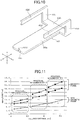
- FIG. 11 illustrates compared results of characteristics of sound generation devices in each of the embodiments described above.
- Practical implementation 1 illustrated in FIG. 11 is the sound generation device 1 in the first embodiment illustrated in FIG. 2 through FIG. 5
- practical implementation 2 is the sound generation device 101 in the second embodiment illustrated in FIG. 6
- practical implementation 3 is the sound generation device 201 in the third embodiment illustrated in FIG. 8 .
- the fulcrum distance Ls a distance (mm) from a deformation starting point on the base end of the armature to a point of application of a driving force of the magnetic field generation unit 20 applied to the armature.
- a 50 mA driving signal was applied to the coil 27 at 1 kHz, and an amplitude (range) in the ⁇ Z-direction of the armature was measured.
- the amplitude of the armature can be made large by forming the frame 5 by the magnetic material.
- the fulcrum distance of the vibration part can be made substantially longer, to enable the amplitude of the armature to become large.
Landscapes
- Engineering & Computer Science (AREA)
- Physics & Mathematics (AREA)
- Acoustics & Sound (AREA)
- Signal Processing (AREA)
- Manufacturing & Machinery (AREA)
- Electromagnetism (AREA)
- Mechanical Engineering (AREA)
- Electrostatic, Electromagnetic, Magneto- Strictive, And Variable-Resistance Transducers (AREA)
Abstract
Description
- The present invention relates to a sound generation device provided with an armature that extends parallel to a vibration plate and vibration of the armature is transmitted to the vibration plate, and to a production method therefor.
-
Patent Document 1 describes an invention related to a sound generation device (sound transducer). - This sound generation device has a holding frame fixed inside a case body. The holding frame has an opening that is covered by a resin film, and a vibration plate formed by a thin metal plate is adhered on the resin film.
- An armature that is formed by a magnetic material is accommodated inside the case body. The armature has a vibration part and a fixed part that are integrally formed, and the fixed part is positioned and fixed to the holding frame. A coil mounting part is formed on the armature, a coil is fixed to this coil mounting part, and the vibration part is arranged within a space part of at a coil winding center.
- A pair of fixing pieces is integrally formed on the armature, and the yoke is fixed in a state sandwiched between the fixing pieces. The yoke is formed by a first member that is bent to a U-shape, and a plate-shaped second member that is fixed in a state across sidewalls of the first member. One magnet is fixed to a bottom inner surface of the first member, and another magnet is fixed to an inner surface of the second member. The vibration part of the armature is positioned between the upper and lower magnets that oppose each other. A free end part of the vibration part and the vibration plate are connected by a beam part.
- In the sound generation device having the structure described above, the armature is magnetized by a voice current applied to the coil, and the vibration part vibrates due to this magnetization and a magnetic field of the magnet. This vibration is transmitted to the vibration plate via the beam part, and sound is generated by the vibration of the vibration plate.
- Patent Document 1: Japanese Laid-Open Patent Publication No.
2012-4850 - In the structure of
Patent Document 1, the fixed part of the armature is fixed to the holding frame, the coil mounting part and the fixing pieces are formed on this armature, the coil is fixed to the coil mounting part, and the yoke is fixed in the state sandwiched between the fixing pieces. According to this structure, the coil and the yoke are mutually positioned and fixed on the armature, before fixing the armature on the holding frame, and for this reason, it is difficult to perform an efficient assembling operation using a robot to successively assemble each of the parts on the holding frame. - In addition, due to size tolerance and mounting tolerance of each of the armature and the yoke accumulating between the holding frame and the magnet and affecting the same, it is difficult to set a mounting accuracy of the magnet with respect to the holding frame, and a parallelism of a magnetization surface of the magnet with respect to the holding frame, to a high accuracy.
- Further, the yoke described in
Patent Document 1 is formed by the first member that is bent to the U-shape, and the plate-shaped second member that is fixed in the state across the sidewalls of the first member. According to this structure, when assembling the yoke, it is necessary to insert the second member between the sidewalls of the first member in a state in which the opposing sidewalls of the first member are opened in a direction so as to separate from each other, and thereafter deform the sidewalls in a direction so as to close upon each other, before fixing both end surfaces of the second member to inner surfaces of the sidewalls. For this reason, the assembling operation is complex, and it is also difficult to perform an automated assembling operation. - The present invention solves the above described problem that is conventionally encountered, and one object of the present invention is to provide a sound generation device and a production method therefor, according to which relative positions of a magnet and an armature can be determined with a high accuracy with reference to a mounting surface of a frame.
- Another object of the present invention is to provide a sound generation device and a production method therefor, according to which each part can be successively assembled with respect to a frame, and an assembling operation can be automated.
- The present invention relates to a sound generation device comprising a vibration plate, an armature extending parallel to the vibration plate, a coil having a conductor wire wound around the armature, a magnetic field generation unit opposing the armature, and a transmitting body that transmits vibration of the armature to the vibration plate, characterized in that:
- the magnetic field generation unit has magnets opposing the armature, and yokes supporting the magnets, and the yokes are fixed on a mounting surface of a frame, and
- a base end part of the armature is fixed with reference to the mounting surface.
- The sound generation device according to the present invention may be configured so that
the magnetic field generation unit has an upper yoke and a lower yoke, and at least 2 side yokes arranged between the upper yoke and the lower yoke,
the upper yoke and the lower yoke are plate-shaped, and plate surfaces thereof are mutually parallel,
the side plates are plate-shaped, and plate surfaces thereof are perpendicular to the plate surfaces of the upper yoke and the lower yoke, respectively, wherein the plate surfaces of the side yokes are mutually parallel and arranged with a gap therebetween, and both end surfaces of the side yokes are fixed to the plate surfaces of the upper yoke and the lower yoke, respectively,
the magnets are fixed on the mutually opposing plate surfaces of the upper yoke and the lower yoke, respectively, and the armature is arranged inside the gap between the magnets opposing each other in up-and-down direction, and
an upper surface of the upper yoke forms a bonding surface that is bonded and fixed to a mounting surface of the yoke by surface bonding. - The sound generation device according to the present invention may be configured so that
the armature has a vibration part, a tip end part connected to the transmitting body, and a base end part connected to the vibration part via a folded part, wherein the vibration part and the base end part extend in parallel, and
the base end part is fixed to the mounting surface. - The sound generation device according to the present invention may be configured so that
the armature has a plate-shape including a vibration part, a tip end part connected to the transmitting body, and a base end part connecting from the vibration part, and
a support member is fixed to the mounting surface, the support member has a parallel support surface formed in parallel to the mounting surface, and the base end part is fixed to the parallel support surface. - The sound generation device according to the present invention may be configured so that
the armature has a vibration part, a tip end part connected to the transmitting body, and a base end part bent in a perpendicular direction from the vibration part, and
a support member is fixed to the mounting surface, the support member has a perpendicular support surface formed perpendicularly to the mounting surface, and the base end part is fixed to the perpendicular support surface. - The sound generation device according to the present invention may preferably be configured so that the frame is formed by a magnetic material. Alternatively, the sound generation device according to the present invention may preferably be configured so that the frame and the support member are formed by a magnetic material.
- Next, the present invention relates to a production method for producing a sound generation device that includes a vibration plate, an armature extending parallel to the vibration plate, a coil having a conductor wire wound around the armature, a magnetic field generation unit opposing the armature, and a transmitting body that transmits vibration of the armature to the vibration plate, characterized in that there are provided:
- fixing, on a mounting surface of a frame, the magnetic field generation unit having magnets opposing the armature, and yokes supporting the magnets;
- setting a base end part of the armature with reference to the mounting surface, and fixing the base end part by moving the armature in parallel to the vibration plate to pass a space at a winding center part of the coil that is arranged adjacent to the magnetic field generation unit, and an opposing part between the magnets; and
- fixing a tip end part of the armature to the transmitting body simultaneously as or, before or after fixing of the base end part.
- The production method for producing the sound generation device according to the present invention may be configured so that
the armature has a vibration part, the tip end part connected to the transmitting body, and the base end part connected to the vibration part via a folded part, wherein the vibration part and the base end part extend in parallel, and
the base end part is fixed to the mounting surface. - The production method for producing the sound generation device according to the present invention may be configured so that
the armature has a plate-shape including a vibration part, the tip end part connected to the transmitting body, and the base end part connecting from the vibration part, and
a support member is fixed to the mounting surface, the support member has a parallel support surface formed in parallel to the mounting surface, and the base end part is fixed to the parallel support surface. - The production method for producing the sound generation device according to the present invention may be configured so that
the armature has a vibration part, the tip end part connected to the transmitting body, and the base end part bent in a perpendicular direction from the vibration part, and
a support member is fixed to the mounting surface, the support member has a perpendicular support surface formed perpendicularly to the mounting surface, and the base end part is fixed to the perpendicular support surface after butting the base end part against the perpendicular support surface and adjusting a distance between the mounting surface and the armature. - The production method for producing the sound generation device according to the present invention may preferably be configured so that
a cavity is formed in the tip end part of the armature, and
the tip end part and the armature are fixed after moving the armature in parallel to the vibration plate and guiding the transmitting body into the cavity. - In the sound generation device of the present invention, the magnetic field generation unit is fixed with reference to the mounting surface formed on the frame, and the armature is fixed with reference to the mounting surface. Hence, by increasing dimensional accuracy of the magnetic field generation unit and dimensional accuracy of the armature, and dimensional accuracy of a support member in a case in which the support member is used, it is possible to maintain the relative positions of the magnet and the armature to at a high accuracy, and maintain parallelism of the magnetization surface of the magnet and the armature at a high degree of parallelism, by assembling each part on the frame.
- In addition, an assembling method of the sound generation device of the present invention can perform the assembling operation to assemble each part on the frame with a high accuracy, and the assembling operation can be automated.
-
-
FIG. 1 is a perspective view illustrating an external appearance of a sound generation device in a first embodiment of the present invention; -
FIG. 2 is a disassembled perspective view of the sound generation device illustrated inFIG. 1 ; -
FIG. 3 is a cross sectional view of the sound generation device illustrated inFIG. 1 cut along a line III-III:-
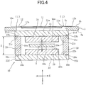
FIG. 4 is a cross sectional view cut along a line IV-IV inFIG. 3 and illustrating a structure of the sound generation device excluding a casing; -
FIG. 5(A) and FIG. 5(B) are cross sectional views for explaining an assembling operation of the sound generation device in the first embodiment; -
FIG. 6(A) and FIG. 6(B) are cross sectional views for explaining the assembling operation of the sound generation device in a second embodiment of the present invention; -
FIG. 7(A) is a perspective view illustrating an armature and a vibration body used in the sound generation device in the second embodiment illustrated inFIG. 6 , andFIG. 7(B) is a perspective view illustrating a modification thereof; -
FIG. 8 is a cross sectional view illustrating the sound generation device in a third embodiment of the present invention; -
FIG. 9 is a side view illustrating the sound generation device in a fourth embodiment of the present invention; -
FIG. 10 is a perspective view illustrating the armature used in the sound generation device in the fourth embodiment; and -
FIG. 11 is a graph illustrating amplitudes of the armatures used in each of the embodiments.
-
-
FIG. 1 through FIG. 3 illustrate asound generation device 1 in a first embodiment of the present invention. - The
sound generation device 1 has acasing 2. Thecasing 2 is formed by alower casing 3 and anupper casing 4. Thelower casing 3 and theupper casing 4 are made of a synthetic resin or a metal that is a nonmagnetic material, by press molding or die-casting. - As illustrated in
FIG. 2 , thelower casing 3 has abottom part 3a, asidewall part 3b surrounding 4 sides, and anopen end 3c at an upper end of thesidewall part 3b. Theupper casing 4 has aceiling part 4a, asidewall part 4b surrounding 4 sides, and anopen end 4c at a lower end of thesidewall part 4b. An internal space of thelower casing 3 is larger than an internal space of theupper casing 4, and theupper casing 4 functions as a lid body for thelower casing 3. - A
frame 5 is sandwiched between theopen end 3c of thelower casing 3 and theopen end 4c of theupper casing 4. Although not illustrated inFIG. 2 , a positioning mechanism using male-female fitting is formed between theopen end 3c of thelower casing 3 and theframe 5, and a positioning mechanism using male-female fitting is formed between theopen end 4c of theupper casing 4 and theframe 5. Thelower casing 3, theupper casing 4, and theframe 5 are positioned by these positioning mechanisms, and thelower casing 3, theupper casing 4, and theframe 5 are fixed to each other by an adhesive agent or the like. - As illustrated in
FIG. 2 , theframe 5 is formed by a plate member having a uniform thickness in a Z-direction, and a lower plane inFIG. 2 forms a drivingend mounting surface 5a, and an upper plane inFIG. 2 forms a vibratingend mounting surface 5b. Anopening 5c at a central part of theframe 5 is formed to penetrate theframe 5 in an up-and-down direction. - As illustrated in
FIG. 3 andFIG. 4 , avibration plate 11 and aflexible sheet 12 are mounted on the vibratingend mounting surface 5b of theframe 5. Thevibration plate 11 is formed by a thin metal material such as aluminum or the like, and is press-molded with a rib to increase bending strength, if necessary. Theflexible sheet 12 is resiliently deformed more easily than thevibration plate 11, and is formed by a resin sheet (resin film) made of PET (Poly-Ethylene Terephthalate), nylon, polyester, or the like. - The
vibration plate 11 is adhered and fixed to a lower surface of theflexible sheet 12, and an outerperipheral part 12a of theflexible sheet 12 is fixed on the vibratingend mounting surface 5b via an adhesive agent, where the vibratingend mounting surface 5b is formed by an upper surface of a frame part of theframe 5. As a result, thevibration plate 11 is supported on theframe 5 via theflexible sheet 12, to freely perform a vibrating operation. - As illustrated in
FIG. 2 ,FIG. 3 , andFIG. 4 , an area of thevibration plate 11 is smaller than an opening area of theopening 5c. An area of theflexible sheet 12 is larger than that of thevibration plate 11, and is also larger than that of theopening 5c. - As illustrated in
FIG. 4 , gaps (i) and (i) are formed between theframe 5 and bothedge parts vibration plate 11 in a X-direction (width direction). As illustrated inFIG. 3 , a gap (ii) is formed between theframe 5 and afree end 11b of thevibration plate 11. A gap (iii) narrower than the gaps (i) and (ii) is formed, or virtually no gap is formed, between theframe 5 and afulcrum end part 11c of thevibration plate 11. The gaps (i), (ii), and (iii) are covered by theflexible sheet 12. Thevibration plate 11 can vibrate using thefulcrum end part 11c as a fulcrum, so that thefree end 11b is displaced in the Z-direction due to deformation and elasticity of theresilient sheet 12. - As illustrated in
FIG. 2 andFIG. 3 , a magneticfield generation unit 20 is mounted on theframe 5. The magneticfield generation unit 20 is assembled from anupper yoke 21, alower yoke 22, and a pair of side yokes 23 and 23. Theupper yoke 21, thelower yoke 22, and the side yokes 23 and 23 are formed by a cold-rolled steel plate that is a magnetic metal material. - In one embodiment, SPCC (for general purpose) prescribed by JIS G 3141 is used as the cold-rolled steel plate. The SPCC is an inexpensive material that can be worked with ease. In addition, SPCD (for drawing), SPCE (for deep drawing), SPCF (for non-aging deep drawing), and SPCG (for non-aging extra deep drawing) prescribed by JIS G 3141 may be used as the cold-rolled steel plate.
- SPCC includes steel (Fe) as a main component, and impurities such as 0.15% or less of carbon (C), 0.60% or less of manganese (Mn), 0.100% or less of phosphor (P), and 0.05% or less of sulfur (S). Saturation flux density of SPCC is approximately 2.0 T (Tesla). A proportion of the impurities in the cold-rolled steel plate is smaller than that of SPCC in the case of SPCD, SPCE, SPCF, and SPCG, in this order. For this reason, the saturation flux density of such cold-rolled steel materials is 2.0 T or higher.
- As illustrated in
FIG. 4 , theupper yoke 21 and thelower yoke 22 respectively have a plate shape, and are arranged in the Z-direction with a gap therebetween. Theupper yoke 21 and thelower yoke 22 have the same rectangular shape with the same size, and have the same thickness. An outer plate surface of theupper yoke 21 facing up inFIG. 4 forms abonding surface 21a to be bonded to theframe 5, and an inner plate surface of theupper yoke 21 facing down inFIG. 4 forms an opposingsurface 21b. An inner plate surface of thelower yoke 22 facing down inFIG. 4 forms an opposingsurface 22b. - The side yokes 23 and 23 have a plate shape, with thicknesses that are the same as the thicknesses of the
upper yoke 21 and thelower yoke 22. Mutually opposing plate surfaces of the side yokes 23 and 23 formside opposing surfaces side opposing surfaces side opposing surfaces surface 21b of theupper yoke 21 and the opposingsurface 22b of thelower yoke 22. - As illustrated in
FIG. 4 , the pair of side yokes 23 and 23 has the same height H in the Z-direction. The side yokes 23 and 23 have upper end surfaces 23b and 23b facing up inFIG. 4 , and lower end surfaces 23c and 23b facing down inFIG. 4 . The upper end surfaces 23b and 23b of the side yokes 23 and 23 are butted against the opposingsurface 21b of theupper yoke 21, and the lower end surfaces 23c and 23c of the side yokes 23 and 23 are butted against the opposingsurface 22b of thelower yoke 22. - As illustrated in
FIG. 4 , recesses 21c and 21c are formed in regions of the opposingsurface 21b of theupper yoke 21 where the upper end surfaces 23b and 23b are bonded. Therecesses sides upper yoke 21, parallel to thesides Recesses surface 22b of thelower yoke 22 where thelower surfaces recesses sides lower yoke 22, parallel to thesides - The
recesses recesses recesses upper yoke 21 and therecesses lower yoke 22, recesses may be formed in the upper end surfaces 23b and 23b of the side yokes 23 and 23, and in the lower end surfaces 23c and 23c of the side yokes 23 and 23. Alternatively, the recesses may be formed in theupper yoke 21 and thelow yoke 22, and also in the upper end surfaces 23b and 23b ad the lower end surfaces 23c and 23c of the side tokes 23 and 23. - An adhesive agent is coated between the upper end surfaces 23b and 23b of the side yokes 23 and 23, and the opposing
surface 21b of theupper yoke 21 to be bonded to the upper end surfaces 23b and 23b, to fix the side yokes 23 and 23 to theupper yoke 21. In this case, the adhesive agent fills therecesses surface 21b are firmly fixed together. Similarly, an adhesive agent is also coated between the lower end surfaces 23c and 23c of the side yokes 23 and 23, and the opposingsurface 22b of thelower yoke 22 to be bonded to the lower end surfaces 23c and 23c, to fix the side yokes 23 and 23 to thelower yoke 22. In this case, the adhesive agent fills therecesses surface 22b are firmly fixed together. - In addition, by providing the
recesses surface 21b is less likely to spread out from the bonding part, and the adhesive agent coated at a bonding part between the lower end surfaces 23c and 23c and the opposingsurface 22b is less likely to spread out from the bonding part. For this reason, the assembling operation of the 4 yokes 21, 22, 23, and 23 can easily be automated. - Further, the upper end surfaces 23b and 23b and the lower end surfaces 23c and 23c of the side yokes 23 and 23 are preferably cut using a wire-saw. By performing this cutting, the height H of the side yokes 23 and 23 can be set with a high accuracy, a flatness of the upper end surfaces 23b and 23b and the lower end surfaces 23c and 23c after the cutting can be set high, and the parallelism of the upper end surfaces 23b and 23b and the lower end surfaces 23c and 23c can be set high. Machining of the
sides recesses upper yoke 21, and machining of thesides recesses lower yoke 21, can be performed by dicing. - As described above, machining of the upper end surfaces 23b and 23b and the lower end surfaces 23c and 23c of the side yokes 23 and 23 can be performed with a high machining accuracy. In addition, by forming the
recesses surface 21b of theupper yoke 21 can be fixed in contiguous contact, and thelower surfaces surface 22b of thelower yoke 22 can be fixed in contiguous contact. - Because the machining accuracy of the side yokes 23 and 23 is high, and the side yokes 23 and 23 can be fixed in contiguous contact with the
upper yoke 21 and thelower yoke 22, an error in an opposing distance H between the opposingsurface 21b of theupper yoke 21 and the opposingsurface 22b of thelower yoke 22 in the Z-direction can be reduced. Further, the opposing distance H can be set with a high accuracy. - As illustrated in
Figs. 2 ,3 , and4 , in the magneticfield generation unit 20, theupper magnet 24 is fixed to the opposingsurface 21b of theupper yoke 21, and thelower magnet 25 is fixed to the opposingsurface 22b of thelower yoke 22. A gap δ is formed between alower surface 24a of theupper magnet 24 and anupper surface 25a of thelower magnet 25 in the Z-direction. Each of themagnets lower surface 24a of theupper magnet 24 and theupper surface 25a of thelower magnet 25 are magnetized to mutually opposite polarities. - As described above, the opposing distance H between the opposing
surface 21b of theupper yoke 21 and the opposingsurface 22b of thelower yoke 22 in the Z-direction can be set with a high accuracy. For this reason, by managing thicknesses of themagnets - An upper surface of the
upper yoke 21 forms thebonding surface 21a, and thebonding surface 21a is a plane. As illustrated inFIG. 4 , thebonding surface 21a is bonded to the drivingend mounting surface 5a at a lower surface of theframe 5, and fixed by the adhesive agent. Alternatively, anupper edge part 21e (refer toFIG. 2 ) of theupper yoke 21 and the drivingend mounting surface 5a are fixed by laser welding. - Because the
bonding surface 21a at the upper surface of theupper yoke 21 and the drivingend mounting surface 5a of theframe 5 are fixed in contiguous contact, the magneticfield generation unit 20 is fixed with reference to the drivingend mounting surface 5a. At the magneticfield generation unit 20, the opposing distance H between the opposingsurfaces magnets lower surface 24a of theupper magnet 24 and theupper surface 25a of thelower magnet 25 with respect to the drivingend mounting surface 5a can be set high, and the distance from the drivingend mounting surface 5a to a center of the gap δ in the Z-direction can be set with a high accuracy. - As illustrated in
FIG. 2 andFIG. 3 , acoil 27 is provided at a position adjacent to the magneticfield generation unit 20. A conductor wire of thecoil 27 is wound around a winding centerline extending in a Y-direction. As will be described later, avibration part 32a of an armature is inserted into aspace 27c at a winding center part of thecoil 27, and the conductor wire of thecoil 27 is wound around a periphery of the armature. - As illustrated in
FIG. 3 , a bonding surface 27a is formed at an end surface facing left in the Y-direction of thecoil 27, and this bonding surface 27a is fixed to theupper yoke 21 and thelower yoke 22 of the magneticfield generation unit 20 by anadhesive agent layer 28. In this case, the bonding surface 27a and the upper andlower yokes coil 27 matches the center of the gap δ between theupper magnet 24 and thelower magnet 25. - An upper surface 27b of the
coil 27 may be butted directly against the drivingend mounting surface 5a at the lower surface of theframe 5, or butted via a spacer, and fixed by a bonding agent. - As illustrated in
FIG. 3 , anarmature 32 is fixed to the drivingend mounting surface 5a at the lower surface of theframe 5 - The
armature 32 is formed by a magnetic material, and may be formed by a cold-rolled steel plate or SUS430 (18-chromium stainless steel), for example. Alternatively, thearmature 32 may be formed by a Ni-Fe alloy. -
FIG. 2 illustrates a shape of thearmature 32. Thearmature 32 is formed by a plate member having a uniform thickness, and has thevibration part 32a, and atip end part 32c at a tip of thevibration part 32a. Acavity 32d is formed at a center part along a width direction of thetip end part 32c. Thecavity 32d opens towards the Y-direction, and an opening width is indicated by W. A U-shaped foldedpart 32b, and abase end part 32e extending from the foldedpart 32b, are integrally formed at a base part of thevibration part 32a. Thevibration part 32a and thebase end part 32e are parallel to each other. A width of thebase end part 32e in the X-direction is greater than widths of thevibration part 32a and the foldedpart 32b. The width of thebase end part 32e in the X-direction is greater than an opening width of theopening 5c of theframe 5 in the X-direction. - The
base end part 32e of thearmature 32 is fixed to the drivingend mounting surface 5a of theframe 5. Theframe 5 and thebase end part 32e are fixed by laser welding or an adhesive agent. As illustrated inFIG. 3 , thevibration part 32a is inserted into thespace 27c at the winding center of thecoil 27, and as further illustrated inFIG. 3 andFIG. 4 , inserted into the gap δ between theupper magnet 24 and thelower magnet 25. Thetip end part 32c of thearmature 32 extends from within the gap δ towards the front in the Y-direction. - As illustrated in
FIG. 3 , thefree end 11b of thevibration plate 11 and thetip end part 32c of thearmature 32 are connected by a transmittingbody 33. The transmittingbody 33 is a needle-shaped member formed by a metal or a synthetic resin, and afixed part 33a at an upper end thereof is fixed to thevibration plate 11. A connectingend part 33b is formed at a lower end part of the transmittingbody 33. The connectingend part 33b is inserted into thecavity 32d of thearmature 32, and the connectingend part 33b and thearmature 32 are fixed by an adhesive agent. - The
frame 5 is preferably formed by a magnetic material. For example, theframe 5 is formed by SUS430 (18-chromium stainless steel). By forming theframe 5 from the magnetic material, when a voice current is applied to thecoil 27 and a magnetic field is induced inside thearmature 32, the magnetic flux can loop through thetip end part 32c of thearmature 32, the space, theframe 5, and thebase end part 32e of thearmature 32. Hence, it is possible to increase the magnetic flux density within thevibration part 32a of thearmature 32. - As illustrated in
FIG. 3 , when thelower casing 3 and theupper casing 4 are fixed by sandwiching theframe 5, the space inside thecasing 2 is separated by thevibration plate 11 and theflexible sheet 12. A sound generation end space is formed by a space above thevibration plate 11 and theflexible sheet 12 inside theupper casing 4, and the sound generation end space communicates to an external space via asound generation opening 4d that is formed in thesidewall part 4b of theupper casing 4. An air intake andexhaust opening 3d is formed in thesidewall part 3b of thelower casing 3, and an internal space of thelower casing 3 below thevibration plate 11 and theflexible sheet 12 communicates to outside air via the air intake andexhaust opening 3d. - Next, an operation of the
sound generation device 1 will be described. - When the voice current is applied to the
coil 27, the magnetic field is induced in thearmature 32. The magnetic field induced in thearmature 32, and a magnetic field generated within the gap δ between theupper magnet 24 and thelower magnet 25 generate vibration in thevibration part 32a of thearmature 32 in the Z-direction. This vibration is transmitted to thevibration plate 11 via the transmittingbody 33, to vibrate thevibration plate 11. In this case, thefree end 11b of thevibration plate 11 supported by theflexible sheet 12 vibrates in the Z-direction using thefulcrum end part 11c as the fulcrum. - Sound pressure is generated in a sound generation space inside the
upper casing 4 due to the vibration of thevibration plate 11, and this sound pressure is output to the outside via thesound generation opening 4d. - In the
sound generation device 1, thebonding surface 21a of theupper yoke 21 of the magneticfield generation unit 20 is fixed to the drivingend mounting surface 5a of theframe 5 by surface bonding. In the magneticfield generation unit 20, the opposing distance H between theupper yoke 21 and thelower yoke 22 is determined with a high accuracy by interposing the side yokes 23 and 24. As a result, the distance from the center of the gap δ between theupper magnet 24 and thelower magnet 25 to the drivingend mounting surface 5a in the Z-direction can be determined with a high accuracy. In addition, thelower surface 24a of theupper magnet 24 and theupper surface 25a of thelower magnet 25 can be set to maintain a high degree of parallelism with respect to the drivingend mounting surface 5a. For this reason, as illustrated inFIG. 3 , the center of the gap δ extending in the Y-direction and the drivingend mounting surface 5a can maintain a high degree of parallelism. - On the other hand, the
base end part 32e of thearmature 32 is fixed directly to the drivingend mounting surface 5a, which is a mounting plane of the magneticfield generation unit 20. Hence, it is possible to reduce a tolerance affecting the relative positions in the Z-direction, between the center of the gap δ between theupper magnet 24 and thelower magnet 25, and a center of a plate thickness of thevibration part 32a of thearmature 32. By setting a height h in the Z-direction of thevibration part 32a and thebase end part 32e of thearmature 32 illustrated inFIG. 5 with a high dimensional accuracy, it becomes possible to arrange thevibration part 32a to the center of the gap δ without requiring adjustment. In addition, thevibration part 32a, thelower surface 24a of theupper magnet 24, and theupper surface 25a of thelower magnet 25 can be set to have a high degree of parallelism. - Alternatively, even in a case in which an adjusting operation is required to align the
vibration part 32a to the center of the gap δ, it is possible to reduce an adjusting width, and the adjusting operation can be simplified compared to the conventional adjusting operation. - Next, an example of production processes of the
sound generation device 11 will be described. In the following, the production method that fixes thearmature 32 without requiring adjustment will be described. - In the production processes of the
sound generation device 1, theflexible sheet 12 having thevibration plate 11 bonded thereto is mounted on the vibratingend mounting surface 5b of theframe 5, and thefixed part 33a at the upper end of the transmittingbody 33 is fixed to thefree end 11b of thevibration plate 11. On the other hand, the magneticfield generation unit 20 having thecoil 27 connected thereto is fixed on the drivingend mounting surface 5a of theframe 5, and thearmature 32 is assembled on the drivingend mounting surface 5a. - In this assembling operation, a suction part on a tip end of an assembling arm that is provided in an automatic assembling apparatus attaches, under suction, to a lower surface of the
vibration part 32a of thearmature 32 inFIG. 5 . - The
armature 32 is moved in a direction (a) indicated inFIG. 5(A) at a position where thetip end part 32c of thevibration part 32a is deviated to the right side from thecoil 27 in this figure, so that thetip end part 32c opposes the right side of thespace 27c of thecoil 27 in this figure. Thereafter, the assembling arm is moved along the Y-direction parallel to thevibration plate 11, and thearmature 32 is moved in a direction (b) indicated inFIG. 5(A) , so that thevibration part 32a of thearmature 32 is inserted inside thespace 27c of thecoil 27 and the gap δ between theupper magnet 24 and thelower magnet 25. - The magnetic
field generation unit 20 is fixed with reference to the drivingend mounting surface 5a of theframe 5. For this reason, when the dimensional accuracy (particularly the height h) of thearmature 32 is determined with a high accuracy, the center of the plate thickness of thevibration part 32a of thearmature 32 matches the center of the gap δ between theupper magnet 24 and thelower magnet 25 with a high accuracy, by moving thearmature 32 in the direction (a) as illustrated inFIG. 5(A) , pushing thebase end part 32e of thearmature 32 against the drivingend mounting surface 5a of the frame, moving thebase end part 32e in the direction (b) while making sliding contact with the drivingend mounting surface 5a, and fixing thearmature 32 on theframe 5 at a predetermined position, as illustrated inFIG. 5(B) . - The assembling operation described above does not require the adjusting operation, and the
base end part 32e of thearmature 32 and theframe 5 can be fixed by laser spot welding or the adhesive agent, immediately after assembling thearmature 32, to complete the assembling. - The plate thickness of the
armature 32 is 0.15 mm to 0.35 mm, and relatively thin. Accordingly, in a case in which thebase end part 32e of thearmature 32 and alower surface 31b of asupport member 31 are fixed by laser welding, it is possible to weld thebase end part 32e and theframe 5 by irradiating the laser on thebase end part 32e from the lower side in the Z-direction. - Alternatively, even in a case in which the assembling operation is performed by adjusting the position of the
armature 32, it is possible to reduce an adjusting range and simplify the adjusting operation. For example, the assembling arm is moved in the Z-direction to move thearmature 32 in the direction (a), and thearmature 32 is adjusted to a position where thearmature 32 does not make contact with the drivingend mounting surface 5a of theframe 5 and is separated from the drivingend mounting surface 5a in the Z-direction by a predetermined distance. Next, the assembling arm is moved in the Y-direction while maintaining the position in the Z-direction, to insert thevibration part 32a inside thespace 27c of thecoil 27 and the gap δ between theupper magnet 24 and thelower magnet 25. After completion of this adjusting operation, thebase end part 32e of thearmature 32 and the drivingend mounting surface 5a of theframe 5 are fixed by the laser spot welding or the adhesive agent, and the assembling of thearmature 32 ends. - By the mounting process including this adjusting operation, it is also possible to match the
vibration part 32a of thearmature 32 to the center of the gap δ between theupper magnet 24 and thelower magnet 25, with a high accuracy. - Accordingly, the magnetic
field generation unit 20 and thearmature 32 are assembled with reference to the drivingend mounting surface 5a that forms a common reference plane. Hence, it is possible to match thevibration part 32a of thearmature 32 to the center of the gap δ between theupper magnet 24 and thelower magnet 25, virtually without performing the adjusting operation, or by only performing a simple adjusting operation when the adjustment is required. - As illustrated in
FIG. 2 , thecavity 32d is formed at thetip end part 32c of thearmature 32, and the opening width W of thecavity 32d is wider than a width (diameter) of the connectingend part 33b at the lower end part of the transmittingbody 33. Accordingly, as illustrated inFIG. 5(A) and FIG. 5(B) , when assembling thearmature 32 by sliding thearmature 32 in the direction (b), it is possible to guide the connectingend part 33b of the transmittingbody 33 into thecavity 32d, without applying an external force with respect to the transmittingbody 33. - After assembling the
armature 32 as described above and fixing thebase end part 32e of thearmature 32 to the drivingend mounting surface 5a, the connectingend part 33b of the transmittingbody 33 and thetip end part 32c of thearmature 32 are fixed by an adhesive agent or the like. -
FIG. 6(A) and FIG. 6(B) illustrate a body of asound generation device 101 in a second embodiment of the present invention. - As illustrated in
FIG. 6 , thissound generation device 101 has asupport member 31 fixed to the drivingend mounting surface 5a at the lower surface of theframe 5. Thesupport member 31 is formed by a magnetic material, such as SUS430 or the like, and aparallel support surface 31a that is parallel to the drivingend mounting surface 5a is formed at a lower surface of thesupport member 31. Anarmature 132 is fixed to theparallel support surface 31a. - As illustrated in
FIG. 7(A) , thearmature 132 is plate-shaped, and has avibration part 132a, abase end part 132b, atip end part 132c, and acavity 132d formed in thetip end part 132c. Thebase end part 132b is formed to have a width in the X-direction wider than thevibration part 132a. - In this
sound generation device 101, when thesupport member 31 is formed to have a height in the Z-direction with a high accuracy, thevibration part 132a can be accurately positioned to the center of the gap δ between theupper magnet 24 and thelower magnet 25, by butting thebase end part 132b against theparallel support surface 31a of thesupport member 31 and fixing thebase end part 132b to theparallel support surface 31a. - An assembling method that is used may hold a lower surface of the
base end part 132b of thearmature 132 by a suction part of an assembling arm, move thearmature 132 in a direction (a) illustrated inFIG. 6(A) andFIG. 7(A) , butting thearmature 132 against theparallel support surface 31a, and moving thearmature 132 in a direction (b) while making sliding contact with theparallel support surface 31a. As illustrated inFIG. 6(B) , thearmature 132 is inserted into thespace 27c of thecoil 27 and the gap δ between theupper magnet 24 and thelower magnet 25, and thebase end part 132b and thesupport member 31 are fixed by laser spot welding or an adhesive agent. - In addition, the connecting
end part 33b of the transmittingbody 33 is guided into thecavity 132d of thearmature 132, and the connectingend part 33b is fixed to thearmature 132 by an adhesive agent. - By the operation described above, the
armature 132 can be assembled without requiring adjustment, and relative positions of the magneticfield generation unit 20 and thevibration part 132a can be set with a high accuracy. - Alternatively, the
armature 132 may be held by the suction part of the assembling arm and moved in the direction (a) as illustrated inFIG. 6(A) , and thearmature 132 may be assembled by moving thearmature 132 in the direction (b) without butting against theparallel support surface 31a while maintaining a distance between the drivingend mounting surface 5a and thevibration part 132a to a predetermined value, to fix thebase end part 132b andparallel support surface 31a by laser spot welding or an adhesive agent. Even in a case in which such an adjusting operation is performed, it is possible to minimize the adjusting width. -
FIG. 7(B) illustrates anarmature 232 in a modification. - This
armature 232 has a width that widens in the X-direction at amagnet opposing part 232e on a tip end to be arranged within the gap δ between theupper magnet 24 and thelower magnet 25, and has a width that narrows in the X-direction at avibration part 232a. - The
magnet opposing part 232e of thisarmature 232 has a large area, and thus, a large driving force can be exhibited by the magnetic flux inside thearmature 232 and the magnetic field of themagnets vibration part 232a narrower than that of themagnet opposing part 232e, it becomes possible to vary a bending modulus of thearmature 232 according to design of the sound generation device. - In the first embodiment illustrated in
FIG. 2 through FIG. 5 and in a third embodiment illustrated inFIG. 8 , the width of the magnet opposing part in the X-direction may similarly be made wider than that of the vibration part. -
FIG. 8 illustrates a body of asound generation device 201 in the third embodiment of the present invention. - An
armature 332 used in thesound generation device 201 has abase end part 332b that is formed by bending a base part of avibration part 332a at right angles (perpendicularly). In addition, aperpendicular support surface 31b, that is perpendicular to the drivingend mounting surface 5a of theframe 5, is formed on thesupport member 31 that is formed by a magnetic material. - In this
sound generation device 201, thearmature 332 is fixed while performing an adjusting operation. - In an assembling operation of the
sound generation device 201, a suction part of an assembling arm holds a lower surface of avibration part 332a of thearmature 332 and moves thearmature 332 in a horizontal direction, to insert thevibration part 332a into thespace 27c of thecoil 27 and the gap δ between themagnets armature 332 is positioned in the Y-direction, by butting thebase end part 332b against theperpendicular support surface 31b. - Further, the
armature 332 that is held by the assembling arm is moved in the Z-direction while thebase end part 332b makes sliding contact with theperpendicular support surface 31b, and the position of thearmature 332 in the Z-direction is adjusted to match thevibration part 332a to the center of the gap δ between themagnets base end part 332b and thesupport member 31 are fixed by laser spot welding or an adhesive agent. In addition, the connectingend part 33b of the transmittingbody 33 is guided into acavity 332d, to bond the connectingend part 33b and thearmature 332. -
FIG. 9 illustrates a body of asound generation device 301 in a fourth embodiment of the present invention. - The
sound generation device 301 in the fourth embodiment uses anarmature 432 illustrated inFIG. 10 . In thearmature 432, acavity 432d is formed at atip end part 432c of avibration part 432a. Abase end part 432b having a width in the Z-direction that is wide is formed at a base part of thevibration part 432a, and vertical foldedparts base end part 432b. Stopparts parts - In this embodiment, by setting the dimensions of the
armature 432 in the Z-direction with a high accuracy, it is also possible to position and fix thearmature 432 by moving thearmature 432 in the Y-direction while butting thestop parts end mounting surface 5a of theframe 5 as illustrated inFIG. 9 . Thevibration part 432a can also be positioned to the center of the gap δ between theupper magnet 24 and thelower magnet 25 of the magneticfield generation unit 20. - Further, as illustrated in
FIG. 9 , by butting thestop parts armature 432 against a side surface on the right side of theupper yoke 21 of the magneticfield generation unit 20 in this figure, it is also possible to position thearmature 432 in the Y-direction. In this case, thestop parts upper yoke 21 may be fixed by laser spot welding or the like, if necessary. - By connecting the
upper yoke 21 of the magneticfield generation unit 20 and thearmature 432 that is formed by a magnetic material, a magnetic circuit reaching thearmature 432 from themagnets frame 5 from a magnetic material. Accordingly, it is possible to form theframe 5 by a nonmagnetic material that may increase a bonding strength of theflexible sheet 12. -
FIG. 11 illustrates compared results of characteristics of sound generation devices in each of the embodiments described above. -
Practical implementation 1 illustrated inFIG. 11 is thesound generation device 1 in the first embodiment illustrated inFIG. 2 through FIG. 5 ,practical implementation 2 is thesound generation device 101 in the second embodiment illustrated inFIG. 6 , andpractical implementation 3 is thesound generation device 201 in the third embodiment illustrated inFIG. 8 . - In each of the
practical implementations FIG. 5(B) ,FIG. 6(B) , andFIG. 8 , the fulcrum distance Ls a distance (mm) from a deformation starting point on the base end of the armature to a point of application of a driving force of the magneticfield generation unit 20 applied to the armature. - Further, in each of the
practical implementations frame 5 formed by SUS430 that is a magnetic material, and the other kind having theframe 5 formed by SUS304 that is a nonmagnetic material. - A 50 mA driving signal was applied to the
coil 27 at 1 kHz, and an amplitude (range) in the ±Z-direction of the armature was measured. - From
FIG. 11 , it may be seen that according to each of the practical implementations, the amplitude of the armature can be made large by forming theframe 5 by the magnetic material. In addition, according to thepractical implementation 1, by forming the foldedpart 32b at the base part of thearmature 32 as illustrated inFIG. 3 andFIG. 5 , the fulcrum distance of the vibration part can be made substantially longer, to enable the amplitude of the armature to become large. -
- 1, 101, 201, 301 Sound Generation Device
- 2 Casing
- 4d Sound Generation Opening
- 5 Frame
- 5a Driving End Mounting Surface
- 5b Vibrating End Mounting Surface
- 11 Vibration Plate
- 12 Flexible Sheet
- 20 Magnetic Field Generation Unit
- 21 Upper Yoke
- 21a Bonding Surface
- 21b Opposing Surface
- 22 Lower Yoke
- 22b Opposing Surface
- 23 Side Yoke
- 23b Upper End Surface
- 23c Lower End Surface
- 24 Upper Magnet
- 25 Lower Magnet
- 27 Coil
- 31 Support Member
- 31a Parallel Support Surface
- 31b Perpendicular Support Surface
- 32 Armature
- 32a Vibration Part
- 32b Folded Part
- 32c Tip End Part
- 32d Cavity
- 32e Base End Part
- 33 Transmitting Body
- 132 Armature
- 132a Vibration Part
- 132b Base End Part
- 132c Tip End Part
- 132d Cavity
- 232 Armature
- 232a Vibration Part
- 232b Base End Part
- 232c Tip End Part
- 232d Cavity
- 232e Magnet Opposing Part
- 332 Armature
- 332a Vibration Part
- 332b Base End Part
- 332c Tip End Part
- 332d Cavity
- 432 Armature
- 432a Vibration Part
- 432b Base End Part
- 432c Tip End Part
- 432d Cavity
- 432e Folded Part
- 432f Stop Part
Claims (12)
- A sound generation device comprising a vibration plate, an armature extending parallel to the vibration plate, a coil having a conductor wire wound around the armature, a magnetic field generation unit opposing the armature, and a transmitting body that transmits vibration of the armature to the vibration plate, characterized in that:the magnetic field generation unit has magnets opposing the armature, and yokes supporting the magnets, and the yokes are fixed on a mounting surface of a frame, anda base end part of the armature is fixed with reference to the mounting surface.
- The sound generation device as claimed in claim 1, wherein
the magnetic field generation unit has an upper yoke and a lower yoke, and at least 2 side yokes arranged between the upper yoke and the lower yoke,
the upper yoke and the lower yoke are plate-shaped, and plate surfaces thereof are mutually parallel,
the side plates are plate-shaped, and plate surfaces thereof are perpendicular to the plate surfaces of the upper yoke and the lower yoke, respectively, wherein the plate surfaces of the side yokes are mutually parallel and arranged with a gap therebetween, and both end surfaces of the side yokes are fixed to the plate surfaces of the upper yoke and the lower yoke, respectively,
the magnets are fixed on the mutually opposing plate surfaces of the upper yoke and the lower yoke, respectively, and the armature is arranged inside the gap between the magnets opposing each other in up-and-down direction, and
an upper surface of the upper yoke forms a bonding surface that is bonded and fixed to a mounting surface of the yoke by surface bonding. - The sound generation device as claimed in claim 1 or 2, wherein
the armature has a vibration part, a tip end part connected to the transmitting body, and a base end part connected to the vibration part via a folded part, wherein the vibration part and the base end part extend in parallel, and
the base end part is fixed to the mounting surface. - The sound generation device as claimed in claim 1 or 2, wherein
the armature has a plate-shape including a vibration part, a tip end part connected to the transmitting body, and a base end part connecting from the vibration part, and
a support member is fixed to the mounting surface, the support member has a parallel support surface formed in parallel to the mounting surface, and the base end part is fixed to the parallel support surface. - The sound generation device as claimed in claim 1 or 2, wherein
the armature has a vibration part, a tip end part connected to the transmitting body, and a base end part bent in a perpendicular direction from the vibration part, and
a support member is fixed to the mounting surface, the support member has a perpendicular support surface formed perpendicularly to the mounting surface, and the base end part is fixed to the perpendicular support surface. - The sound generation device as claimed in any of claims 1 to 3, wherein the frame is formed by a magnetic material.
- The sound generation device as claimed in claim 4 or 5, wherein the frame and the support member are formed by a magnetic material.
- A production method for producing a sound generation device that includes a vibration plate, an armature extending parallel to the vibration plate, a coil having a conductor wire wound around the armature, a magnetic field generation unit opposing the armature, and a transmitting body that transmits vibration of the armature to the vibration plate, characterized in that there are provided:fixing, on a mounting surface of a frame, the magnetic field generation unit having magnets opposing the armature, and yokes supporting the magnets;setting a base end part of the armature with reference to the mounting surface, and fixing the base end part by moving the armature in parallel to the vibration plate to pass a space at a winding center part of the coil that is arranged adjacent to the magnetic field generation unit, and an opposing part between the magnets; andfixing a tip end part of the armature to the transmitting body simultaneously as or, before or after fixing of the base end part.
- The production method for producing the sound generation device as claimed in claim 8, wherein
the armature has a vibration part, the tip end part connected to the transmitting body, and the base end part connected to the vibration part via a folded part, wherein the vibration part and the base end part extend in parallel, and
the base end part is fixed to the mounting surface. - The production method for producing the sound generation device as claimed in claim 8, wherein
the armature has a plate-shape including a vibration part, the tip end part connected to the transmitting body, and the base end part connecting from the vibration part, and
a support member is fixed to the mounting surface, the support member has a parallel support surface formed in parallel to the mounting surface, and the base end part is fixed to the parallel support surface. - The production method for producing the sound generation device as claimed in claim 8, wherein
the armature has a vibration part, the tip end part connected to the transmitting body, and the base end part bent in a perpendicular direction from the vibration part, and
a support member is fixed to the mounting surface, the support member has a perpendicular support surface formed perpendicularly to the mounting surface, and the base end part is fixed to the perpendicular support surface after butting the base end part against the perpendicular support surface and adjusting a distance between the mounting surface and the armature. - The production method for producing the sound generation device as claimed in any of claims 8 to 11, wherein
a cavity is formed in the tip end part of the armature, and
the tip end part and the armature are fixed after moving the armature in parallel to the vibration plate and guiding the transmitting body into the cavity.
Applications Claiming Priority (2)
| Application Number | Priority Date | Filing Date | Title |
|---|---|---|---|
| JP2015183078 | 2015-09-16 | ||
| PCT/JP2016/068485 WO2017047187A1 (en) | 2015-09-16 | 2016-06-22 | Sound generation device and production method therefor |
Publications (2)
| Publication Number | Publication Date |
|---|---|
| EP3352477A1 true EP3352477A1 (en) | 2018-07-25 |
| EP3352477A4 EP3352477A4 (en) | 2018-08-29 |
Family
ID=58288788
Family Applications (1)
| Application Number | Title | Priority Date | Filing Date |
|---|---|---|---|
| EP16846060.8A Withdrawn EP3352477A4 (en) | 2015-09-16 | 2016-06-22 | Sound generation device and production method therefor |
Country Status (5)
| Country | Link |
|---|---|
| US (1) | US20180184210A1 (en) |
| EP (1) | EP3352477A4 (en) |
| JP (1) | JPWO2017047187A1 (en) |
| CN (1) | CN108028993A (en) |
| WO (1) | WO2017047187A1 (en) |
Families Citing this family (7)
| Publication number | Priority date | Publication date | Assignee | Title |
|---|---|---|---|---|
| JP6625899B2 (en) * | 2016-02-24 | 2019-12-25 | リオン株式会社 | Electromechanical transducer |
| US11617049B2 (en) | 2018-12-25 | 2023-03-28 | Suzhou Sensorfun Electronics Co., Ltd | Receiver |
| CN111726713A (en) * | 2019-03-22 | 2020-09-29 | 苏州三色峰电子有限公司 | Telephone receiver |
| WO2022021414A1 (en) * | 2020-07-31 | 2022-02-03 | 华为技术有限公司 | Loudspeaker and electronic device |
| CN113519170A (en) * | 2020-07-31 | 2021-10-19 | 华为技术有限公司 | Speakers and Electronic Equipment |
| CN113645559A (en) * | 2021-08-11 | 2021-11-12 | 湖南省拓联精密科技有限公司 | TWS earphone assembling equipment |
| CN114083074A (en) * | 2021-12-09 | 2022-02-25 | 苏州声美达电子科技有限公司 | Production process of moving iron unit assembly with high welding quality |
Family Cites Families (8)
| Publication number | Priority date | Publication date | Assignee | Title |
|---|---|---|---|---|
| JPS58104597A (en) * | 1981-12-17 | 1983-06-22 | Matsushita Electric Ind Co Ltd | Electromagnetic converter |
| US5960093A (en) * | 1998-03-30 | 1999-09-28 | Knowles Electronics, Inc. | Miniature transducer |
| DE19954880C1 (en) * | 1999-11-15 | 2001-01-25 | Siemens Audiologische Technik | Electro-magnetic converter for sound production in hearing aid |
| JP2002300698A (en) * | 2001-04-02 | 2002-10-11 | Star Micronics Co Ltd | Receivers and portable communication devices |
| JP5598109B2 (en) * | 2010-06-17 | 2014-10-01 | ソニー株式会社 | Acoustic transducer |
| JP5540920B2 (en) * | 2010-06-17 | 2014-07-02 | ソニー株式会社 | Acoustic transducer |
| KR20150004079A (en) * | 2013-07-02 | 2015-01-12 | 삼성전자주식회사 | Device for improving performance of balanced armature transducer and the device thereof |
| JP5653543B1 (en) * | 2014-01-21 | 2015-01-14 | リオン株式会社 | Electromechanical transducer and electroacoustic transducer |
-
2016
- 2016-06-22 JP JP2017539721A patent/JPWO2017047187A1/en not_active Withdrawn
- 2016-06-22 WO PCT/JP2016/068485 patent/WO2017047187A1/en not_active Ceased
- 2016-06-22 EP EP16846060.8A patent/EP3352477A4/en not_active Withdrawn
- 2016-06-22 CN CN201680052008.XA patent/CN108028993A/en active Pending
-
2018
- 2018-02-23 US US15/903,158 patent/US20180184210A1/en not_active Abandoned
Also Published As
| Publication number | Publication date |
|---|---|
| CN108028993A (en) | 2018-05-11 |
| WO2017047187A1 (en) | 2017-03-23 |
| EP3352477A4 (en) | 2018-08-29 |
| JPWO2017047187A1 (en) | 2018-07-12 |
| US20180184210A1 (en) | 2018-06-28 |
Similar Documents
| Publication | Publication Date | Title |
|---|---|---|
| US20180184210A1 (en) | Sound generation device and production method therefor | |
| US8630439B2 (en) | Acoustic conversion device and acoustic conversion device assembly method | |
| CN108028994B (en) | Sound producing device | |
| US20190238993A1 (en) | Sound generating device and method of manufacturing sound generating device | |
| JP6438867B2 (en) | Sound generator | |
| JP6014787B1 (en) | Sound generator | |
| JP2005236844A (en) | Electroacoustic transducer | |
| JP2017059988A (en) | Sound generator | |
| WO2017047198A1 (en) | Sound generation device and production method therefor | |
| KR102307552B1 (en) | Acoustic device and vibration structure therefor | |
| JP6697145B2 (en) | Sounding device | |
| JP2017059987A (en) | Sound generator | |
| TWI680679B (en) | Pronunciation device | |
| JP6476321B2 (en) | Production method of sound generator | |
| CN216216448U (en) | Vibration motor | |
| US12009704B2 (en) | Actuator, coil and adhesive layer | |
| WO2018034015A1 (en) | Sound generation device and production method therefor | |
| WO2017212696A1 (en) | Sound-producing device | |
| JP2021016020A (en) | Sound production device | |
| JP6618619B2 (en) | Production method of sound generator |
Legal Events
| Date | Code | Title | Description |
|---|---|---|---|
| PUAI | Public reference made under article 153(3) epc to a published international application that has entered the european phase |
Free format text: ORIGINAL CODE: 0009012 |
|
| 17P | Request for examination filed |
Effective date: 20180307 |
|
| AK | Designated contracting states |
Kind code of ref document: A1 Designated state(s): AL AT BE BG CH CY CZ DE DK EE ES FI FR GB GR HR HU IE IS IT LI LT LU LV MC MK MT NL NO PL PT RO RS SE SI SK SM TR |
|
| AX | Request for extension of the european patent |
Extension state: BA ME |
|
| A4 | Supplementary search report drawn up and despatched |
Effective date: 20180727 |
|
| RIC1 | Information provided on ipc code assigned before grant |
Ipc: H04R 31/00 20060101ALI20180723BHEP Ipc: H04R 11/02 20060101AFI20180723BHEP |
|
| DAV | Request for validation of the european patent (deleted) | ||
| DAX | Request for extension of the european patent (deleted) | ||
| 18W | Application withdrawn |
Effective date: 20190117 |
|
| R18W | Application withdrawn (corrected) |
Effective date: 20190115 |