JP6625899B2 - Electromechanical transducer - Google Patents
Electromechanical transducer Download PDFInfo
- Publication number
- JP6625899B2 JP6625899B2 JP2016033192A JP2016033192A JP6625899B2 JP 6625899 B2 JP6625899 B2 JP 6625899B2 JP 2016033192 A JP2016033192 A JP 2016033192A JP 2016033192 A JP2016033192 A JP 2016033192A JP 6625899 B2 JP6625899 B2 JP 6625899B2
- Authority
- JP
- Japan
- Prior art keywords
- armature
- displacement
- magnets
- electromechanical converter
- pair
- Prior art date
- Legal status (The legal status is an assumption and is not a legal conclusion. Google has not performed a legal analysis and makes no representation as to the accuracy of the status listed.)
- Active
Links
- 238000006073 displacement reaction Methods 0.000 claims description 37
- 230000004907 flux Effects 0.000 claims description 30
- 230000007246 mechanism Effects 0.000 claims description 9
- 230000000149 penetrating effect Effects 0.000 claims description 5
- 230000003014 reinforcing effect Effects 0.000 description 12
- 239000000463 material Substances 0.000 description 7
- 229920006395 saturated elastomer Polymers 0.000 description 5
- 230000007423 decrease Effects 0.000 description 4
- 238000010586 diagram Methods 0.000 description 4
- 230000035945 sensitivity Effects 0.000 description 4
- 230000008859 change Effects 0.000 description 3
- 230000006870 function Effects 0.000 description 3
- 238000003466 welding Methods 0.000 description 3
- 239000000853 adhesive Substances 0.000 description 2
- 230000001070 adhesive effect Effects 0.000 description 2
- 230000000052 comparative effect Effects 0.000 description 2
- 238000013461 design Methods 0.000 description 2
- 230000000694 effects Effects 0.000 description 2
- 239000000696 magnetic material Substances 0.000 description 2
- 229910000889 permalloy Inorganic materials 0.000 description 2
- 238000012545 processing Methods 0.000 description 2
- 230000002787 reinforcement Effects 0.000 description 2
- 238000009738 saturating Methods 0.000 description 2
- 230000009471 action Effects 0.000 description 1
- 238000013459 approach Methods 0.000 description 1
- 238000005452 bending Methods 0.000 description 1
- 230000005540 biological transmission Effects 0.000 description 1
- 238000007796 conventional method Methods 0.000 description 1
- 230000005415 magnetization Effects 0.000 description 1
- 239000007769 metal material Substances 0.000 description 1
- 230000002093 peripheral effect Effects 0.000 description 1
- 238000003825 pressing Methods 0.000 description 1
- 230000009467 reduction Effects 0.000 description 1
- 230000001105 regulatory effect Effects 0.000 description 1
- 239000007787 solid Substances 0.000 description 1
- 229910001220 stainless steel Inorganic materials 0.000 description 1
- 239000010935 stainless steel Substances 0.000 description 1
Images


Classifications
-
- H—ELECTRICITY
- H02—GENERATION; CONVERSION OR DISTRIBUTION OF ELECTRIC POWER
- H02K—DYNAMO-ELECTRIC MACHINES
- H02K33/00—Motors with reciprocating, oscillating or vibrating magnet, armature or coil system
- H02K33/02—Motors with reciprocating, oscillating or vibrating magnet, armature or coil system with armatures moved one way by energisation of a single coil system and returned by mechanical force, e.g. by springs
-
- H—ELECTRICITY
- H04—ELECTRIC COMMUNICATION TECHNIQUE
- H04R—LOUDSPEAKERS, MICROPHONES, GRAMOPHONE PICK-UPS OR LIKE ACOUSTIC ELECTROMECHANICAL TRANSDUCERS; DEAF-AID SETS; PUBLIC ADDRESS SYSTEMS
- H04R11/00—Transducers of moving-armature or moving-core type
- H04R11/02—Loudspeakers
-
- H—ELECTRICITY
- H04—ELECTRIC COMMUNICATION TECHNIQUE
- H04R—LOUDSPEAKERS, MICROPHONES, GRAMOPHONE PICK-UPS OR LIKE ACOUSTIC ELECTROMECHANICAL TRANSDUCERS; DEAF-AID SETS; PUBLIC ADDRESS SYSTEMS
- H04R25/00—Deaf-aid sets, i.e. electro-acoustic or electro-mechanical hearing aids; Electric tinnitus maskers providing an auditory perception
Description
本発明は、電気信号を機械振動に変換する電気機械変換器に関し、特にアーマチュア、ヨーク、コイル、磁石等からなる駆動部を備えた電気機械変換器に関するものである。 The present invention relates to an electromechanical converter for converting an electric signal into a mechanical vibration, and more particularly to an electromechanical converter including a driving unit including an armature, a yoke, a coil, a magnet, and the like.
補聴器等に用いられる電気機械変換器や電気音響変換器は、アーマチュア、ヨーク、コイル、磁石などからなる駆動部を備え、コイルに供給される電気信号に応じてアーマチュアを駆動し、アーマチュアと他の部材との間の相対振動を機械振動や音響に変換するように構成される。例えば、所謂バランスド・アーマチュア型(以下、バランス型と呼ぶ)の電磁型変換器の例として、特許文献1には、U字型のアーマチュアを用いた磁気回路の構造例が開示され、特許文献2には、平板状のアーマチュアの両端とヨークとの間をそれぞれバネ部材により挟持する構造例が開示されている。上記いずれの場合も、コイルに電流が流れないときは、アーマチュアに対して上下の磁石により作用する磁気力が釣り合うように構成される。一方、コイルに電流が流れるときは、上下の磁石からアーマチュアに対して磁気力が働き、磁気力と復元力が釣り合う位置までアーマチュアが相対的に変位する。この場合の復元力は、特許文献1の場合にはアーマチュア自身の弾性力により与えられ、特許文献2の場合にはバネ部材の弾性力により与えられる。
Electromechanical transducers and electro-acoustic transducers used for hearing aids and the like include a driving unit including an armature, a yoke, a coil, a magnet, etc., and drive the armature in accordance with an electric signal supplied to the coil, so that the armature and other It is configured to convert relative vibration between the member and the member into mechanical vibration or sound. For example, as an example of a so-called balanced armature type (hereinafter, referred to as a balanced type) electromagnetic converter,
一般に、上記バランス型の電磁型変換器においては、コイルに電流を流さない状態で、アーマチュアに対して上下の磁石に向かう外力を加えると、磁気力の作用でアーマチュアが上部又は下部の磁石に吸引されるが、外力を取り除くとアーマチュアは釣り合いの位置に戻る。すなわち、アーマチュアが磁石に吸引されることを防止するには、可動範囲内でどの位置にあったとしても、磁石に向かう磁気力(吸引力)に比べて釣り合いの位置に向かう復元力が大きくなるように設計する必要がある。 In general, in the above-mentioned balanced electromagnetic converter, when an external force is applied to the upper and lower magnets to the armature in a state where no current flows through the coil, the armature is attracted to the upper or lower magnet by the action of the magnetic force. However, when the external force is removed, the armature returns to the equilibrium position. That is, in order to prevent the armature from being attracted to the magnet, the restoring force toward the balanced position is greater than the magnetic force (attraction force) toward the magnet, regardless of the position within the movable range. Need to be designed.
電気機械変換器の小型高出力化を実現するには、電気機械変換器の駆動力をできるだけ大きくすることが望ましい。そのためには、アーマチュアの釣り合いの位置の近傍で、磁気力のアーマチュアの変位量に対する比(負のスティフネス)を大きくして、アーマチュアの復元力(弾性力)のスティフネスに近い値にする必要がある。しかし、上述したようにアーマチュアの可動範囲内で復元力を磁気力より大きくしなければならず、磁気力がアーマチュアの変位に対して非線形に変化することを考慮すると(図8及びその説明参照)、アーマチュアの釣り合いの位置の近傍でアーマチュアの復元力のスティフネスと負のスティフネス(絶対値)を十分に近い値にすることは難しい。以上のように、上記従来の技術によれば、電気機械変換器の良好な磁気特性と信頼性を維持しつつ、入力電力に対する駆動力が大きい電気機械変換器を実現することは困難であった。 In order to reduce the size and output of the electromechanical converter, it is desirable to increase the driving force of the electromechanical converter as much as possible. To this end, it is necessary to increase the ratio (negative stiffness) of the magnetic force to the amount of displacement of the armature near the position where the armature is balanced, so as to have a value close to the stiffness of the restoring force (elastic force) of the armature. . However, as described above, the restoring force must be larger than the magnetic force within the movable range of the armature, and considering that the magnetic force changes non-linearly with respect to the displacement of the armature (see FIG. 8 and its description). It is difficult to make the restoring force stiffness and negative stiffness (absolute value) of the armature sufficiently close to each other near the position where the armature is balanced. As described above, according to the conventional technique, it is difficult to realize an electromechanical converter having a large driving force with respect to input power while maintaining good magnetic characteristics and reliability of the electromechanical converter. .
本発明はこれらの問題を解決するためになされたものであり、良好な磁気特性と信頼性を維持しつつ、入力電力に対して駆動力を十分に高めることが可能な電気機械変換器を提供することを目的とする。 The present invention has been made to solve these problems, and provides an electromechanical converter capable of sufficiently increasing a driving force with respect to input power while maintaining good magnetic characteristics and reliability. The purpose is to do.
上記課題を解決するために、本発明は、電気信号を機械振動に変換する電気機械変換器であって、少なくとも1対の磁石(15〜18)、前記磁石による磁束を導くヨーク(12、13)、前記電気信号が供給されるコイル(14)を一体的に配置した構造部と、前記構造部の内部空間を貫く内側部(19a)、前記内側部から第1の方向の両側に突出した第1の外側部(19b)及び第2の外側部(19c)を有し、前記内側部のうち互いに逆向きの前記磁束が導かれる2つの領域を介して前記構造部と磁気回路を構成し、前記磁気回路の磁気力に基づく変位方向に変位するアーマチュア(19)と、前記第1の外側部と前記構造部との間に挟持され、前記アーマチュアの変位に応じた復元力を前記第1の外側部に付与する第1の弾性機構(20、21)と、前記第2の外側部と前記構造部との間に挟持され、前記アーマチュアの変位に応じた復元力を前記第2の外側部に付与する第2の弾性機構(22、23)とを備えて構成され、前記アーマチュアは、前記2つの領域の間の所定位置における断面積が前記2つの領域における断面積に比べて小さい形状を有し、前記アーマチュアの変位の範囲内において前記アーマチュアを前記第1の方向に流れる磁束が飽和する特性を有する。
In order to solve the above problems, the present invention relates to an electromechanical converter for converting an electric signal into mechanical vibration, comprising at least one pair of magnets (15 to 18), and a yoke (12, 13) for guiding magnetic flux by the magnets. ), A structure in which the coil (14) to which the electric signal is supplied is integrally arranged, an inner portion (19a) penetrating the internal space of the structure, and projecting from the inner portion to both sides in the first direction. It has a first outer portion (19b) and a second outer portion (19c), and forms a magnetic circuit with the structural portion through two regions of the inner portion through which the magnetic fluxes of opposite directions are guided. An armature (19) displaced in a displacement direction based on a magnetic force of the magnetic circuit, and a restoring force according to the displacement of the armature sandwiched between the first outer portion and the structural portion; First elastic mechanism applied to the outer portion of the
本発明の電気機械変換器によれば、アーマチュアは、コイルに電流が流れないときに釣り合いの位置にあり、コイルに電流を流したときに内側部に加わる磁気力によって構造部に対して相対的に変位し、その際に第1及び第2の弾性機構によりアーマチュアに復元力が作用する。一方、コイルに電流が流れないときにアーマチュアに外力を加えて変位させると第1の方向の磁束が発生するが、変位量が大きくなるとアーマチュアの断面積が小さい部分に制約されて磁束が飽和する。よって、アーマチュアに作用する負のスティフネスの最大値と釣り合いの位置での負のスティフネスの値との差を小さくできるため、入力電力に対する電気機械変換器の駆動力を十分に高めることが可能となる。 According to the electromechanical transducer of the present invention, the armature is in a balanced position when no current flows through the coil, and is relatively positioned with respect to the structure by the magnetic force applied to the inner portion when current flows through the coil. , And at this time, a restoring force acts on the armature by the first and second elastic mechanisms. On the other hand, when an external force is applied to the armature to displace it when no current flows through the coil, a magnetic flux in the first direction is generated. However, when the displacement is large, the magnetic flux is saturated by being restricted to a portion having a small cross-sectional area of the armature. . Therefore, the difference between the maximum value of the negative stiffness acting on the armature and the value of the negative stiffness at the balance position can be reduced, and the driving force of the electromechanical converter with respect to the input power can be sufficiently increased. .
本発明のアーマチュアは、前述の断面積の条件を満たす限り多様な形状で形成することができるが、例えば、第1の方向及び変位方向に直交する第2の方向におけるアーマチュアの幅を、前記2つの領域に比べて所定位置で小さくすることができる。この場合、アーマチュアを、変位方向で一定の厚さを有する平板状の部材とすることが望ましい。以上により、アーマチュアを部分的に細い形状とすればよいので、加工が比較的容易であり、厚さを薄くする場合に比べて耐衝撃性への影響が小さくなる。なお、アーマチュアの平面視の形状として、例えば、アーマチュアの内側部のうち第2の方向の両側に対称配置された凹部を形成することができる。 The armature of the present invention can be formed in various shapes as long as the above-mentioned condition of the cross-sectional area is satisfied. For example, the width of the armature in the first direction and the second direction orthogonal to the direction of displacement is set to 2 It can be smaller at a predetermined position than in one area. In this case, it is desirable that the armature is a flat member having a constant thickness in the displacement direction. As described above, since the armature may have a partially thin shape, the processing is relatively easy, and the influence on the impact resistance is reduced as compared with the case where the thickness is reduced. In addition, as the shape of the armature in plan view, for example, concave portions symmetrically arranged on both sides in the second direction in the inner portion of the armature can be formed.
本発明において、アーマチュアの2つの領域には、少なくとも1対の磁石があれば磁気回路を構成することができるが、それぞれギャップを介して対向する2対の磁石を配置することが望ましい。これにより、アーマチュアの両側のそれぞれの領域において、アーマチュアを通す互いに逆向きの2つの磁束を容易に形成することができる。 In the present invention, a magnetic circuit can be formed in at least one pair of magnets in the two regions of the armature. However, it is desirable to arrange two pairs of magnets facing each other via a gap. Thereby, in the respective regions on both sides of the armature, two mutually opposite magnetic fluxes passing through the armature can be easily formed.
本発明の第1及び第2の弾性機構として、アーマチュアを挟んで変位方向に対称配置された1対の弾性部材を用いることができる。例えば、1対の弾性部材は、アーマチュアを挟んで変位方向に対称配置された1対のバネ部材である。1対のバネ部材を用いることにより、アーマチュアに対する適切な復元力に応じたバネ定数を容易に設定することができる。 As the first and second elastic mechanisms of the present invention, a pair of elastic members symmetrically arranged in the displacement direction with the armature interposed therebetween can be used. For example, the pair of elastic members is a pair of spring members symmetrically arranged in the displacement direction across the armature. By using a pair of spring members, a spring constant according to an appropriate restoring force for the armature can be easily set.
本発明によれば、アーマチュアの2つの領域の間の断面積を部分的に小さくすることで、アーマチュアの変位の範囲内においてアーマチュアを第1の方向に流れる磁束を飽和させることができ、良好な磁気特性と信頼性を維持しつつ、入力電力に対する大きい駆動力を得ることが可能な電気機械変換器を実現することが可能となる。 According to the present invention, by partially reducing the cross-sectional area between two regions of the armature, it is possible to saturate the magnetic flux flowing through the armature in the first direction within the range of displacement of the armature. An electromechanical converter capable of obtaining a large driving force with respect to input power while maintaining magnetic characteristics and reliability can be realized.
本発明の好適な実施形態について、図面を参照しながら説明する。ただし、以下に述べる実施形態は本発明を適用した形態の一例であって、本発明が本実施形態の内容により限定されることはない。以下では、電気信号を機械振動に変換する電気機械変換器に対して本発明を適用した実施形態について説明する。 A preferred embodiment of the present invention will be described with reference to the drawings. However, the embodiment described below is an example of an embodiment to which the present invention is applied, and the present invention is not limited by the contents of the present embodiment. Hereinafter, an embodiment in which the present invention is applied to an electromechanical converter that converts an electric signal into mechanical vibration will be described.
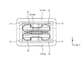
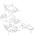
以下、図1〜図5を参照して、本実施形態の電気機械変換器の基本構造について説明する。図1は、本実施形態の電気機械変換器の全体を収容するハウジング10を取り外した状態の構造を示す斜視図である。図2〜図4は本実施形態の電気機械変換器を互いに直交する各方向から見たときの図であり、便宜上X方向、Y方向、Z方向をそれぞれ矢印にて示している。図2は、本実施形態の電気機械変換器をZ方向の一方(図1の紙面上端側)から見たときの上面図(後述のハウジング部材10b、ヨーク13の一部、磁石16を欠いた一部欠け端面図)であり、図3は、本実施形態の電気機械変換器の図2のA−A断面における断面図であり、図4は、本実施形態の電気機械変換器の図2のB−B断面における断面図である。また、図5は、本実施形態の電気機械変換器における後述の磁気回路部の分解斜視図である。なお、本実施形態の電気機械変換器は、上、下、左、右の方向性を持たないが、以下では説明の便宜のため、各図面を見たときの紙面の方向(X、Y、Z)に応じて、上、下、左、右の方向を記載する場合がある。
Hereinafter, the basic structure of the electromechanical converter of the present embodiment will be described with reference to FIGS. FIG. 1 is a perspective view illustrating a structure in which a
図1に示すように、本実施形態の電気機械変換器の全体を収容するハウジング10は、上下対称に配置された下部のハウジング部材10a及び上部のハウジング部材10bを一体化した構造を有する。ハウジング10には、電気機械変換器の後述の駆動部11が収容されている。ハウジング10は、駆動部11を支持し得る強度の範囲内で、例えば、プラスチック材料又はステンレス等の軽い金属材料が用いられる。図1〜図4に示すように、下部のハウジング部材10a及び上部のハウジング部材10bの各々の内部には、駆動部11が可動範囲内でY方向に過度に動くことを抑制するための4つのストッパーSが形成されている。なお、実際には図1の構造を有するハウジング10は電気機械変換器の全体を覆っているが、図2〜図4では、ハウジング10を部分的に除去して内部を見た構造を示している。
As shown in FIG. 1, a
駆動部11は、1対のヨーク12、13、コイル14、4つの磁石15、16、17、18、アーマチュア19、4つのアーマチュア補強板P1、4つのバネ部材20、21、22、23により構成される。駆動部11のうち、ヨーク12、13、コイル14、4つの磁石15〜18が一体的に配置された本発明の構造部として機能し、この構造部の内部空間を貫くアーマチュア19が駆動部11に対して、バネ部材20〜23により可動に配置されている。また、図1〜図4では図示を省略しているが、コイル14からは、電気信号を供給するための1対のリード線が延出され、それがハウジング10の外側の一端に設けた1対の電気端子と電気的に接続されている。
The driving
下部のヨーク12と上部のヨーク13がZ方向に対向配置された状態で、例えば溶接により一体的に固定される。図5に示すように、各々のヨーク12、13の中央部には、それぞれ内面を向く凹部12a、13aが形成され、空芯のコイルが上下のヨーク12、13の各凹部12a、13aに挟まれるように配置されている。このとき、コイル14は、空芯部(貫通孔)の両端がX方向に開口した状態で、ヨーク12、13の中央に位置決めされ、ヨーク12、13の内面側と接着剤で固定されている。ヨーク12、13の材料としては、例えば、45%Niのパーマロイ等の軟磁性材料を用いることができる。
The
ヨーク12、13には、X方向の両側に突出したバネ部材取付部12b、12c、13b、13cがそれぞれ形成されている。図3に示すように、ヨーク12のバネ部材取付部12b、12cのそれぞれのアーマチュア19に対向する側にはバネ部材20、22がそれぞれ当接し、ヨーク13のバネ部材取付部13b、13cのそれぞれのアーマチュア19に対向する側にはバネ部材21、23がそれぞれ当接する。また、4つのバネ部材取付部12b、12c、13b、13cの各々には、Y方向の両側に切欠きが形成され、この部分にバネ部材20〜23の後述のヨーク取付部21c(図6)の部分が係合する。つまり、4つのバネ部材取付部12b、12c、13b、13cとバネ部材20〜23は、接着や溶接などにより固定されない。なお、バネ部材20〜23の具体的な構造については後述する。
On the
ヨーク12、13の内側のX方向の両側には、磁石15〜18が対称的に配置されている。すなわち、1対の磁石15、16は、ヨーク12、13のX方向の一端の各対向面に接着固定され、所定の距離を置いて対向配置されている。同様に、1対の磁石17、18は、ヨーク12、13のX方向の他端の各対向面に接着固定され、所定の距離を置いて対向配置されている。
On both sides of the
アーマチュア19は、X方向に長尺の板状部材であり、1対の磁石15、16の間の空間と、コイル14の貫通孔と、1対の磁石17、18の間の空間をそれぞれ貫くように配置されている。図5に示すように、アーマチュア19は、ヨーク12、13に対向する空間(構造部の内部空間)に位置する内側部19aと、内側部19aの両側に突出した外側部19b、19cからなる。アーマチュア19の内側部19aのうち、X方向の中央部には1対の円弧状の凹部Cが形成されるとともに、凹部Cが形成されていない領域はY方向で磁石15〜18と同程度の幅を有する。1対の凹部Cの役割は、アーマチュア19のY方向の幅を部分的に小さくすることで、アーマチュア19をX方向に貫く磁束を飽和させることにあるが、詳細については後述する。また、アーマチュア19の外側部19b、19cは、Y方向で内側部19aよりも細い幅の矩形部分を部分的に切り欠いて形成される。アーマチュア19の材料としては、ヨーク12、13と同様、例えば、45%Niのパーマロイ等の軟磁性材料を用いることができる。
The
アーマチュア19の両方の外側部19b、19cから内側部19aの両端にかけて、その両面に2対(4個)のアーマチュア補強板P1(図3)が溶接されている。アーマチュア補強板P1の各々は、図2に示すように、Y方向で外側部19b、19cの切欠き部分と同じ幅を有する矩形であり、アーマチュア19のうちバネ部材20〜23を取り付ける部分の厚みを確保する役割がある。なお、磁気回路やバネ部材20〜23の設計を考慮して、アーマチュア19の厚みを十分に確保できる場合には、アーマチュア補強板P1を設けなくてもよい。
Two pairs (four) of armature reinforcing plates P1 (FIG. 3) are welded to both surfaces of the
図3に示すように、アーマチュア19の上下(Z方向の両面)には、磁石15〜18との間に平行な隙間が形成されており、それぞれの隙間がギャップG1、G2、G3、G4(図7参照)を構成する。4つの磁石15〜18は互いに同形状でX方向及びZ方向に対称配置されることから、4つのギャップG1〜G4も互いに同形状である。ギャップG1〜G4は、アーマチュア19が、その通常動作の範囲内でZ方向に変位したとき、コイル14及び磁石15〜18と接触しない程度の適当な隙間(厚さ)となっている。
As shown in FIG. 3, parallel gaps are formed between the
また、アーマチュア19の両側の外側部19b、19cの各々は、その両端が前述のアーマチュア補強板P1を介して上下のハウジング部材10a、10bに挟まれた状態で接着剤等により固定される。なお、ハウジング10は、アーマチュア19の両端を除いて、駆動部11とは接触しない構造となっている。アーマチュア19とハウジング10との結合部分は、駆動部11で発生した振動がハウジング10に確実に伝達されるように十分な剛性を持たせる必要がある。図5に示すように、アーマチュア19の両側の外側部19b、19cの形状は、ヨーク12、13のバネ部材取付部12b、13b、12c、13cのそれぞれの対向する部分の形状とZ方向で重なっている。
Each of the
4つのバネ部材20〜23はそれぞれ板状部材を折り曲げ加工して形成された板バネであり、1対のバネ部材20、21(本発明の第1の弾性機構)がアーマチュア19の一方の外側部19bに取り付けられるとともに、1対のバネ部材22、23(本発明の第2の弾性機構)がアーマチュア19の他方の外側部19cに取り付けられている。バネ部材20〜23の役割は、アーマチュア19が磁気回路内で構造部に対して相対的に変位したとき、その変位の大きさに比例する復元力をアーマチュア19に与えることにある。図4に示すように、下部のバネ部材20(22)と、上部のバネ部材21(23)は、アーマチュア19の外側部19b(19c)を上下から挟みつつ、Z方向に対称配置されている。以下、各々のバネ部材20〜23の構造について、図6の斜視図を参照しつつ説明する。
The four
図6においては、代表してバネ部材21の構造を示しているが、他のバネ部材20、22、23についても同様の構造を有している。図6に示すように、バネ部材21は、Y方向の両側の2つの湾曲部21a、21bと、中央で上下に対向する内向き凹部としてのヨーク取付部21c及びアーマチュア取付部21dと、バネ部材補強部21eとを含む。なお、不図示のバネ部材20、22、23に関しても、上記と同様の湾曲部20a、20b、22a、22b、23a、23b、ヨーク取付部20c、22c、23c、アーマチュア取付部20d、22d、23d、バネ部材補強部20e、22e、23eを含むものとする。また、バネ部材補強部21eは、ヨーク取付部21cの内側面(バネ部材21の内周側)に溶接されている。バネ部材21の形成に用いる板状部材の両端がヨーク取付部21cにおいて、バネ部材補強部21eによって接合され、ひとつながりのリング状に形成されている。バネ部材21に切れ目がない場合には、バネ部材補強部21eを設ける必要はない。なお、バネ部材21は、一体的に本発明の弾性部材として機能する。
FIG. 6 shows the structure of the
図6のバネ部材21の形状は、図4に示すように、ヨーク取付部21cの凹形状がヨーク13のバネ部材取付部13bの形状に係合し、アーマチュア取付部21dの凹状断面がアーマチュア19及びアーマチュア補強板P1の形状に係合する。これらの係合箇所は、接着や溶接などで固定されないが、バネ部材21を駆動部11に組み込んだとき、それぞれの凹形状によってバネ部材21のX及びY方向への動きを規制することができる。バネ部材21は、ヨーク13のバネ部材取付部13bとアーマチュア補強板P1とにそれぞれ当接した状態で安定に挟持される。なお、バネ部材20は、バネ部材21とはZ方向に対称的な配置で挟持される。また、図4に示すように、1対のバネ部材20、21(22、23)は、その押圧力によってアーマチュア19を釣り合いの位置に保持するため、Z方向に若干潰れた状態となっている。
6, the concave shape of the yoke mounting portion 21c engages with the shape of the spring member mounting portion 13b of the
本実施形態のバネ部材20〜23の設計に際しては、アーマチュア19に付与すべき復元力に応じたバネ定数を得られるように、板バネの形状、材質、板厚、あるいは湾曲部21a、21bの曲率などを定める必要がある。バネ部材20〜23の材質としては、例えば、非磁性のバネ用SUS材などを用いることができる。また、バネ部材20〜23の板厚は、例えば、0.1mm程度に設定することができる。
When designing the
次に、本実施形態の電気機械変換器の基本的な動作について説明する。図7は、図3の横断面図のうちの磁気回路を構成するヨーク12、13、コイル14、磁石15〜18、アーマチュア19の部分を模式的に表した図である。説明の簡略化のため、アーマチュア19に付随するアーマチュア補強板P1は図示を省略し、磁気回路を構成しない他の部材についても図示を省略する。図7に示すように、コイル14を挟んでZ方向に対向配置された1対の磁石15、16及び1対の磁石17、18は、互いに逆方向に着磁されている。例えば、図7の右側の磁石15、16は下方向に磁化され、図7の左側の磁石17、18は上方向に磁化される。このように磁化された磁石15〜18により、ヨーク12、13及びアーマチュア19には、実線矢印にて示す磁束B1が発生する。
Next, a basic operation of the electromechanical converter of the present embodiment will be described. FIG. 7 is a diagram schematically illustrating portions of the
そして、磁束B1のうちギャップG1〜G4を通る磁束による磁気力がアーマチュア19に作用する。具体的には、アーマチュア19に対し、下側のギャップG1、G3の磁気力が強くなると下向きの力が作用するとともに、上側のギャップG2、G4の磁気力が強くなると上向きの力が作用する。これら4つの力が釣り合っていない場合には、アーマチュア19は力の大きい方に変位する。よって、コイル14に電流が流れていない状態で上記4つの力が釣り合うようにアーマチュア19が位置決めされる。このとき、アーマチュア19が変位しないので、ギャップG1を通る磁束とギャップG2を通る磁束がほぼ等しく、かつ、ギャップG3を通る磁束とギャップG4を通る磁束もほぼ等しい状態にある。そのため、アーマチュア19のうちコイル14に囲まれた部分には正味の磁束が流れない状態にある。
The magnetic force of the magnetic flux B1 that passes through the gaps G1 to G4 acts on the
この状態でコイル14に電流を流す場合、アーマチュア19のうちコイル14に囲まれた部分には、電流の方向に応じた向きの磁束が発生する。例えば、図7は、コイル電流により、アーマチュア19に点線矢印で示す磁束B2が発生する状態を示している。このとき、図7における各磁束B1、B2の方向性を考慮すると、磁束B2の発生により、下側のギャップG1、G3の磁束はそれぞれ増加し、上側のギャップG2、G4の磁束はそれぞれ減少する。その結果、アーマチュア19は下向きの磁気力を受けて下向きに変位する。
When a current flows through the
アーマチュア19が下向きに変位したとき、バネ部材20〜23(図3)により、変位を元の位置に戻そうとする復元力が作用する。アーマチュア19が変位したときバネ部材20〜23の復元力の和が、アーマチュア19に働く磁気力に比べて大きい場合は、アーマチュア19が磁石14、16に吸着することは避けられる。以上の動作は、所謂バランスド・アーマチュア型の電磁型変換器の動作原理と同様である。なお、コイル電流が上記と逆向きである場合は、アーマチュア19が上向きの磁気力を受けて上向きに変位する状態を想定すればよい。
When the
ここで、アーマチュア19以外のヨーク12、13、コイル14、磁石15〜18からなる部分(本発明の構造部)とアーマチュア19との相対振動を考える。上述したように、コイル14への電気信号の印加時に流れる電流に応じた駆動力が発生し、この駆動力が上述の相対振動を生じさせる。アーマチュア19の両端とハウジング10とが十分な剛性をもって固定されるので、アーマチュア19と構造部との間に発生した駆動力は、アーマチュア19を通してハウジング10に伝達され、ハウジング10に振動を生じさせる。以上のように、本実施形態の電気機械変換器は、外部から印加される電気信号に対応する機械振動を発生するように構成される。
Here, the relative vibration between the
次に、本実施形態の電気機械変換器において、アーマチュア19に働く力と変位との関係について図8及び図9を用いて説明する。図8は、本実施形態の電気機械変換器との対比のための比較例として、図5の凹部Cが形成されない従来型のアーマチュア(例えば、特許文献2に記載のアーマチュア19)を用いた場合のアーマチュア19の変位量に対する磁気力及び負のスティフネスの計算結果の例を示している。なお、図8の計算においては、アーマチュア19の形状を除き、図3と同様の断面構造及び図7と同様の磁気回路を想定するとともに、漏洩磁束を無視し、アーマチュア19及びヨーク12、13の磁気抵抗を無視し、アーマチュア19がギャップG1〜G4内で変位したときに磁石15〜18の磁化が変化しないことを仮定している。
Next, the relationship between the force acting on the
図8の横軸に示すxは、図7と同様の磁気回路を想定したとき、アーマチュア19の釣り合いの位置からのZ方向の変位量を空隙長(ギャップG1〜G4の厚さ)で規格化した量である。すなわち、x=0はアーマチュア19が上下の磁石15〜18の磁気力の釣り合いの位置(変位なし)にある場合に対応し、x=1はアーマチュア19が上部の磁石16、18に接触する位置(アーマチュア19の可動範囲の上限位置)に対応する。また、図8の縦軸には、上部の磁石16、18によりアーマチュア19に印加される磁気力Fm(右側のスケール)と、この磁気力Fmをアーマチュア19の変位量で割った量である負のスティフネスSm(左側のスケール:絶対値で表示)とを併せて示している。なお、アーマチュア19及び磁気回路のZ方向の対称性から、図8はx<0の領域でも同様の変化を示す。
The x shown on the horizontal axis in FIG. 8 indicates the amount of displacement in the Z direction from the equilibrium position of the
図8に示すように、アーマチュア19が釣り合いの位置(x=0)から変位するにつれ、磁気力Fmが大きくなる。一般に、磁気力Fmは変位量に対して線形ではなく、高次の項を含むので、図8における磁気力Fmの傾きに対応する負のスティフネスSmはxとともに増加している。この場合、ギャップG1〜G4内を変位するアーマチュア19が上下の磁石15〜18に接触しないためには、バネ部材20〜23によってアーマチュア19に働く復元力が常に磁気力Fmより大きくなければならない。すなわち、アーマチュア19の可動範囲のどの位置でも、バネ部材20〜23のバネ定数(スティフネス)を負のスティフネスSmより大きく設定する必要がある。ここで、負のスティフネスSmの最大値をSmmaxと表すとすると、図8の例では、x=1のとき、Smmax=25000程度であり、この値よりバネ部材20〜23のスティフネスSeを大きくする必要がある。
As shown in FIG. 8, as the
一方、電気機械変換器における入力電力に対する変位量として規定される感度は、アーマチュア19の図8の特性に依存して定まる。すなわち、スティフネスが支配的な低周波帯域を想定すると、アーマチュア19の変位が小さいx=0近傍では、電気機械変換器の感度は、バネ部材20〜23のスティフネスSeと負のスティフネスSmとの差(Se−Sm)に依存して定まり、この差(Se―Sm)が小さいほど感度が上昇する。図8において、負のスティフネスSmに関し、前述の最大値Smmaxとx=0のときの値Sm(0)との差をΔSとすると、ΔSは次の(1)式のように表される。
ΔS=Smmax−Sm(0) (1)
前述したように、バネ部材20〜23のスティフネスSeは負のスティフネスの最大値Smmaxより大きくする必要があるので(Smmax≦Se)、電気機械変換器の感度の最大値は、(1)式の差ΔSの逆数に比例することになる。
On the other hand, the sensitivity defined as the amount of displacement with respect to the input power in the electromechanical converter is determined depending on the characteristic of the
ΔS = Sm max −Sm (0) (1)
As described above, since the stiffness
また、電気機械変換器の駆動力は、アーマチュア19の変位量とバネ部材20〜23のスティフネスSeとの積に一致する。よって、電気機械変換器への入力電力が一定である場合、駆動力をできる限り大きくするためには、バネ部材20〜23のスティフネスSeを、アーマチュア19の変位の範囲内での負のスティフネスの最大値Smmaxに一致させる必要がある。結局、入力電力に対する駆動力の大きさは、Smmaxに比例し、ΔSに反比例することになる。この場合の係数は、次の(2)式のように書き換えることができる。
Smmax/ΔS={1−Sm(0)/Smmax}-1 (2)
よって、(2)式の右辺のSm(0)/Smmaxを1に近付けることで、入力電力に対する駆動力の大きさを非常に大きい値にすることができる。図8の例では、Sm(0)/Smmaxが約0.64であるので、Smmax/ΔSが約2.8となるが、Smmax/ΔSを0.9以上にできれば、Smmax/ΔSが10以上となるので、駆動力を3倍以上に増加させることが可能である。
The driving force of the electromechanical converter is equal to the product of the displacement of the
Sm max / ΔS = {1−Sm (0) / Sm max } −1 (2)
Therefore, by making Sm (0) / Sm max on the right side of Expression (2) close to 1, the magnitude of the driving force with respect to the input power can be made a very large value. In the example of FIG. 8, since Sm (0) / Sm max is about 0.64, Sm max / ΔS is about 2.8. However, if Sm max / ΔS can be made 0.9 or more, Sm max / S Since ΔS is 10 or more, it is possible to increase the driving force three times or more.
次に図9は、本実施形態の電気機械変換器におけるアーマチュア19を用いる場合の図8と同様の条件による計算結果の例を示している。図9における横軸及び縦軸と各パラメータの意味は図8で説明した通りである。また、図10は、図8及び図9の計算結果に対応するアーマチュア19の平面視の形状を対比して示している。図10(A)は、図8に対応する従来型のアーマチュア19のXY面内の平面図であり、図10(B)は、図9に対応する本実施形態のアーマチュア19のXY面内の平面図である。図10(A)及び図10(B)の相違は、図10(B)のアーマチュア19に内側部19aに形成された1対の円弧状の凹部Cが、図10(A)のアーマチュア19の内側部19aには形成されていない点のみである。
Next, FIG. 9 shows an example of a calculation result under the same conditions as those in FIG. 8 when the
上述の相違により、アーマチュア19の内側部19aのY方向に関して、図10(A)では一定の幅であるの対し、図10(B)でY方向の幅が凹部Cの部分で短くなり、中央部で最も細くなっている。ここで、アーマチュア19のZ方向の厚さは図10(A)と図10(B)で共通であるので、図10(B)の中央部でのアーマチュア19の断面積は、図10(A)に比べて中央部の幅の比率だけ小さくなる。ここで、アーマチュア19をX方向に貫く磁束φは、磁束密度Bと断面積Aとにより、φ=A・Bと表すことができ、アーマチュア19が所定の磁束密度で磁気飽和したときの磁束φの最大値は断面積Aに比例することになる。本実施形態の構造上の特徴は、アーマチュア19に凹部Cを形成して部分的に断面積Aを小さくすることで、以下に述べるようにアーマチュア19を変位の範囲内で磁気飽和させることにある。
Due to the above difference, the width of the
すなわち、図9に示すように、アーマチュア19の釣り合いの位置の近傍では、磁気力Fm及び負のスティフネスSmは、図8と概ね同様に変化するが、アーマチュア19の変位量がある程度大きくなると、アーマチュア19をX方向に貫く磁束が飽和し始め、磁気力Fmの傾きが緩やかになるとともに、負のスティフネスSmが減少していく。本実施形態では、アーマチュア19の変位の範囲内の適切な位置でアーマチュア19のX方向の磁束が飽和するように、アーマチュア19の前述の断面積Aを設定するものである。
That is, as shown in FIG. 9, in the vicinity of the position where the
上記の作用に基づき、図9に示すように、x=0.4の付近でアーマチュア19が磁気飽和することで、それより変位量が増加した場合の磁気力Fmの増え方が極めて緩やかになるとともに、負のスティフネスSmが減少することになる。その結果、図9に示すように、負のスティフネスSmの最大値Smmaxとx=0のときの値Sm(0)との差ΔSが小さくなり、前述したように(2)式におけるSm(0)/Smmaxが1に近付くことになるので、電気機械変換器における入力電力に対する駆動力の大きさを極めて大きい値に設定することが可能となる。例えば、図9の例ではSm(0)/Smmaxが約0.9であるので、Smmax/ΔSは約10となり、図8の例と比べた場合、駆動力を3倍以上に増加させることができる。なお、図9で磁気飽和が発生する変位量は、アーマチュア19の内側部19aにおける凹部Cがない箇所と凹部Cにより最も幅が細くなる箇所との幅の比に依存するので、図9の所望の特性に応じて凹部Cの部分の幅を設定することが重要である。
Based on the above operation, as shown in FIG. 9, the
なお、本実施形態ではアーマチュア19の内側部19aに凹部Cを形成して部分的にY方向の幅を細くする形状を示しているが、内側部10の全体のY方向の幅を細くする形状も想定される。しかし、このような形状では、前述の磁気飽和が生じたとしても、アーマチュア19が磁石15〜18及びギャップG1〜G4と対向する部分の対向面積が縮小するので、アーマチュア19に対する磁気力が十分に得られなくなる。従って、アーマチュア19の凹部Cは、磁石15〜18及びギャップG1〜G4と対向する2つの領域に挟まれた所定位置に形成することが望ましい。アーマチュア19全体の厚さを薄くして内側部19aの断面積を小さくすることによっても本発明と同様の効果が得られるが、一般的に所望の厚さのアーマチュア材料を入手することが容易ではない場合があり、本発明の方が設計の自由度が大きい。
In the present embodiment, the shape in which the concave portion C is formed in the
本実施形態では、アーマチュア19に内側部19aに凹部Cを形成し、アーマチュア19のY方向の幅を部分的に狭くしているが、かかる構造には限定されることなく、アーマチュア19の内側部19aの断面積を部分的に小さくできれば、上述の作用効果を実現することができる。例えば、アーマチュア19の内側部19aのZ方向の厚さを部分的に小さくしてもよい。ただし、アーマチュア19の厚さが薄くなることによる耐衝撃性の低下などへの対策が必要である。また、アーマチュア19の厚さを薄くするよりも、上述の凹部Cを形成するほうが、比較的加工が容易となる。なお、アーマチュア19に形成される上述の凹部Cは、円弧状に限らず、矩形状など多様な形状とすることができ、Y方向に非対称の形状であってもよい。
In the present embodiment, the concave portion C is formed in the
以上、本実施形態に基づいて本発明に係る電気機械変換器について説明したが、本発明は上述の実施形態に限定されるものではなく、その要旨を逸脱しない範囲で種々の変更を施すことができる。例えば、本実施形態では、電気信号を機械振動に変換する電気機械変換器に対して本発明を適用する場合を説明したが、本発明は、電気信号を音響に変換して外部に出力する電気音響変換器に対しても適用可能である。さらに、本発明に係る電気機械変換器は、例えば、使用者の耳甲介腔に装用する補聴器に適用することができる。これにより、電気機械変換器の振動自体とそのハウジングの振動によって発生した音の両方を伝達手段として機能させ、使用者の耳に音を伝達することができる。このような電気機械変換器を、例えば、耳甲介腔に装用する補聴器に適用する場合、ハウジング10の外形形状を耳甲介腔装用に適した形状とすることが望ましい。
As described above, the electromechanical converter according to the present invention has been described based on the present embodiment. However, the present invention is not limited to the above embodiment, and various changes can be made without departing from the gist thereof. it can. For example, in the present embodiment, the case where the present invention is applied to an electromechanical converter that converts an electric signal into mechanical vibration has been described. It is also applicable to acoustic transducers. Further, the electromechanical transducer according to the present invention can be applied to, for example, a hearing aid worn in a concha of a user's concha. Thereby, both the vibration itself of the electromechanical transducer and the sound generated by the vibration of the housing thereof can function as a transmission means, and the sound can be transmitted to the user's ear. When such an electromechanical transducer is applied, for example, to a hearing aid to be worn in the concha of the concha, it is desirable that the outer shape of the
10…ハウジング
11…駆動部
12、13…ヨーク
14…コイル
15、16、17、18…磁石
19…アーマチュア
20、21、22、23…バネ部材
P1…アーマチュア補強板
G1、G2、G3、G4…ギャップ
DESCRIPTION OF
Claims (7)
少なくとも1対の磁石と、前記磁石による磁束を導くヨークと、前記電気信号が供給されるコイルとを一体的に配置した構造部と、
前記構造部の内部空間を貫く内側部と、前記内側部から第1の方向の両側に突出した第1の外側部及び第2の外側部とを有し、前記内側部のうち互いに逆向きの前記磁束が導かれる2つの領域を介して前記構造部と磁気回路を構成し、前記磁気回路の磁気力に基づく変位方向に変位するアーマチュアと、
前記第1の外側部と前記構造部との間に挟持され、前記アーマチュアの変位に応じた復元力を前記第1の外側部に付与する第1の弾性機構と、
前記第2の外側部と前記構造部との間に挟持され、前記アーマチュアの変位に応じた復元力を前記第2の外側部に付与する第2の弾性機構と、
を備え、
前記アーマチュアは、前記2つの領域の間の所定位置における断面積が前記2つの領域における断面積に比べて小さい形状を有し、前記アーマチュアの変位の範囲内において前記アーマチュアを前記第1の方向に流れる磁束が飽和することを特徴とする電気機械変換器。 In an electromechanical transducer that converts an electric signal into mechanical vibration,
At least one pair of magnets, a yoke that guides magnetic flux by the magnets, and a structural unit that integrally arranges a coil to which the electric signal is supplied,
An inner portion penetrating the internal space of the structure portion, and a first outer portion and a second outer portion protruding from the inner portion on both sides in a first direction, wherein the inner portion has opposite directions. An armature that forms a magnetic circuit with the structure through two regions through which the magnetic flux is guided, and that is displaced in a displacement direction based on a magnetic force of the magnetic circuit;
A first elastic mechanism that is sandwiched between the first outer portion and the structure portion and that applies a restoring force to the first outer portion according to the displacement of the armature;
A second elastic mechanism that is sandwiched between the second outer portion and the structure portion, and that applies a restoring force to the second outer portion according to the displacement of the armature;
With
The armature has a shape in which a cross-sectional area at a predetermined position between the two regions is smaller than a cross-sectional area in the two regions, and moves the armature in the first direction within a range of displacement of the armature. An electromechanical converter characterized by saturation of flowing magnetic flux.
Priority Applications (4)
| Application Number | Priority Date | Filing Date | Title |
|---|---|---|---|
| JP2016033192A JP6625899B2 (en) | 2016-02-24 | 2016-02-24 | Electromechanical transducer |
| DK17157361.1T DK3211919T3 (en) | 2016-02-24 | 2017-02-22 | Electromechanical transducer |
| US15/439,750 US10447132B2 (en) | 2016-02-24 | 2017-02-22 | Electromechanical transducer |
| EP17157361.1A EP3211919B1 (en) | 2016-02-24 | 2017-02-22 | Electromechanical transducer |
Applications Claiming Priority (1)
| Application Number | Priority Date | Filing Date | Title |
|---|---|---|---|
| JP2016033192A JP6625899B2 (en) | 2016-02-24 | 2016-02-24 | Electromechanical transducer |
Publications (2)
| Publication Number | Publication Date |
|---|---|
| JP2017152903A JP2017152903A (en) | 2017-08-31 |
| JP6625899B2 true JP6625899B2 (en) | 2019-12-25 |
Family
ID=58185286
Family Applications (1)
| Application Number | Title | Priority Date | Filing Date |
|---|---|---|---|
| JP2016033192A Active JP6625899B2 (en) | 2016-02-24 | 2016-02-24 | Electromechanical transducer |
Country Status (4)
| Country | Link |
|---|---|
| US (1) | US10447132B2 (en) |
| EP (1) | EP3211919B1 (en) |
| JP (1) | JP6625899B2 (en) |
| DK (1) | DK3211919T3 (en) |
Families Citing this family (7)
| Publication number | Priority date | Publication date | Assignee | Title |
|---|---|---|---|---|
| JP6813423B2 (en) | 2017-04-25 | 2021-01-13 | リオン株式会社 | Electromechanical transducer |
| JP6994429B2 (en) * | 2018-04-27 | 2022-01-14 | リオン株式会社 | Electromechanical transducers and electroacoustic transducers |
| CN108696810A (en) * | 2018-05-17 | 2018-10-23 | 深圳倍声声学技术有限公司 | A kind of moving-iron receiver |
| CN209200903U (en) * | 2018-12-17 | 2019-08-02 | 瑞声科技(南京)有限公司 | Vibrating motor |
| US11617049B2 (en) * | 2018-12-25 | 2023-03-28 | Suzhou Sensorfun Electronics Co., Ltd | Receiver |
| CN110012398B (en) * | 2019-05-14 | 2024-03-12 | 潘国昌 | Balanced vibration system |
| JP2022170144A (en) * | 2021-04-28 | 2022-11-10 | 日本電産サンキョー株式会社 | actuator |
Family Cites Families (11)
| Publication number | Priority date | Publication date | Assignee | Title |
|---|---|---|---|---|
| JP3631935B2 (en) * | 2000-03-14 | 2005-03-23 | スター精密株式会社 | Electroacoustic transducer |
| US7817815B2 (en) * | 2000-05-09 | 2010-10-19 | Knowles Electronics, Llc | Armature for a receiver |
| US7471801B2 (en) * | 2002-05-10 | 2008-12-30 | Osseofon Ab | Device for the generation of or monitoring of vibrations |
| US7869610B2 (en) | 2005-11-30 | 2011-01-11 | Knowles Electronics, Llc | Balanced armature bone conduction shaker |
| US8385583B2 (en) * | 2008-08-29 | 2013-02-26 | The Penn State Research Foundation | Methods and apparatus for reduced distortion balanced armature devices |
| CN103428618A (en) * | 2012-05-18 | 2013-12-04 | 周巍 | Armature device used for moving-iron type loudspeaker or receiver |
| JP6276511B2 (en) * | 2013-03-15 | 2018-02-07 | リオン株式会社 | Electromechanical transducer and electroacoustic transducer |
| KR20150004079A (en) | 2013-07-02 | 2015-01-12 | 삼성전자주식회사 | Device for improving performance of balanced armature transducer and the device thereof |
| JP5653543B1 (en) | 2014-01-21 | 2015-01-14 | リオン株式会社 | Electromechanical transducer and electroacoustic transducer |
| JP5579335B1 (en) * | 2014-02-18 | 2014-08-27 | リオン株式会社 | Electromechanical transducer |
| EP3352477A4 (en) * | 2015-09-16 | 2018-08-29 | Alps Electric Co., Ltd. | Sound generation device and production method therefor |
-
2016
- 2016-02-24 JP JP2016033192A patent/JP6625899B2/en active Active
-
2017
- 2017-02-22 DK DK17157361.1T patent/DK3211919T3/en active
- 2017-02-22 EP EP17157361.1A patent/EP3211919B1/en active Active
- 2017-02-22 US US15/439,750 patent/US10447132B2/en active Active
Also Published As
| Publication number | Publication date |
|---|---|
| EP3211919A1 (en) | 2017-08-30 |
| US10447132B2 (en) | 2019-10-15 |
| US20170244309A1 (en) | 2017-08-24 |
| DK3211919T3 (en) | 2019-03-25 |
| EP3211919B1 (en) | 2018-12-26 |
| JP2017152903A (en) | 2017-08-31 |
Similar Documents
| Publication | Publication Date | Title |
|---|---|---|
| JP5653543B1 (en) | Electromechanical transducer and electroacoustic transducer | |
| JP6625899B2 (en) | Electromechanical transducer | |
| JP6276511B2 (en) | Electromechanical transducer and electroacoustic transducer | |
| US8995705B2 (en) | Multi-layer armature for moving armature receiver | |
| US11070119B2 (en) | Manufacturing method of vibrating actuator | |
| KR20110063792A (en) | Methods and apparatus for reduced distortion balanced armature devices | |
| JP5802547B2 (en) | Electromechanical transducer, electroacoustic transducer and hearing aid using the same | |
| DK202070705A1 (en) | Electro-mechanical converter and electroacoustic converter | |
| JP5579335B1 (en) | Electromechanical transducer | |
| JP6813423B2 (en) | Electromechanical transducer | |
| JP6625896B2 (en) | Electromechanical transducer | |
| US20230370782A1 (en) | Electromechanical transducer |
Legal Events
| Date | Code | Title | Description |
|---|---|---|---|
| A621 | Written request for application examination |
Free format text: JAPANESE INTERMEDIATE CODE: A621 Effective date: 20181227 |
|
| A977 | Report on retrieval |
Free format text: JAPANESE INTERMEDIATE CODE: A971007 Effective date: 20191025 |
|
| TRDD | Decision of grant or rejection written | ||
| A01 | Written decision to grant a patent or to grant a registration (utility model) |
Free format text: JAPANESE INTERMEDIATE CODE: A01 Effective date: 20191119 |
|
| A61 | First payment of annual fees (during grant procedure) |
Free format text: JAPANESE INTERMEDIATE CODE: A61 Effective date: 20191128 |
|
| R150 | Certificate of patent or registration of utility model |
Ref document number: 6625899 Country of ref document: JP Free format text: JAPANESE INTERMEDIATE CODE: R150 |
|
| R250 | Receipt of annual fees |
Free format text: JAPANESE INTERMEDIATE CODE: R250 |