EP3351990A1 - Vorrichtung zur projektion eines verpixelten lichtstrahls, und mit einer solchen vorrichtung ausgestatteter scheinwerfer - Google Patents
Vorrichtung zur projektion eines verpixelten lichtstrahls, und mit einer solchen vorrichtung ausgestatteter scheinwerfer Download PDFInfo
- Publication number
- EP3351990A1 EP3351990A1 EP17207778.6A EP17207778A EP3351990A1 EP 3351990 A1 EP3351990 A1 EP 3351990A1 EP 17207778 A EP17207778 A EP 17207778A EP 3351990 A1 EP3351990 A1 EP 3351990A1
- Authority
- EP
- European Patent Office
- Prior art keywords
- pixels
- matrices
- matrix
- primary
- pair
- Prior art date
- Legal status (The legal status is an assumption and is not a legal conclusion. Google has not performed a legal analysis and makes no representation as to the accuracy of the status listed.)
- Granted
Links
- 230000003287 optical effect Effects 0.000 claims abstract description 118
- 239000011159 matrix material Substances 0.000 claims abstract description 91
- 238000011144 upstream manufacturing Methods 0.000 claims abstract description 12
- 238000011084 recovery Methods 0.000 claims description 46
- 238000003491 array Methods 0.000 claims description 20
- 230000007547 defect Effects 0.000 description 14
- 238000004519 manufacturing process Methods 0.000 description 8
- 230000004075 alteration Effects 0.000 description 4
- 239000000463 material Substances 0.000 description 4
- 230000006378 damage Effects 0.000 description 3
- 230000003247 decreasing effect Effects 0.000 description 3
- 239000000470 constituent Substances 0.000 description 2
- 230000003213 activating effect Effects 0.000 description 1
- 230000000712 assembly Effects 0.000 description 1
- 238000000429 assembly Methods 0.000 description 1
- 230000008901 benefit Effects 0.000 description 1
- 230000005540 biological transmission Effects 0.000 description 1
- 230000008859 change Effects 0.000 description 1
- 238000010276 construction Methods 0.000 description 1
- 230000002950 deficient Effects 0.000 description 1
- 239000000446 fuel Substances 0.000 description 1
- 238000005286 illumination Methods 0.000 description 1
- 230000008672 reprogramming Effects 0.000 description 1
- 239000004065 semiconductor Substances 0.000 description 1
Images


Classifications
-
- G—PHYSICS
- G02—OPTICS
- G02B—OPTICAL ELEMENTS, SYSTEMS OR APPARATUS
- G02B26/00—Optical devices or arrangements for the control of light using movable or deformable optical elements
- G02B26/08—Optical devices or arrangements for the control of light using movable or deformable optical elements for controlling the direction of light
- G02B26/10—Scanning systems
-
- F—MECHANICAL ENGINEERING; LIGHTING; HEATING; WEAPONS; BLASTING
- F21—LIGHTING
- F21S—NON-PORTABLE LIGHTING DEVICES; SYSTEMS THEREOF; VEHICLE LIGHTING DEVICES SPECIALLY ADAPTED FOR VEHICLE EXTERIORS
- F21S41/00—Illuminating devices specially adapted for vehicle exteriors, e.g. headlamps
- F21S41/10—Illuminating devices specially adapted for vehicle exteriors, e.g. headlamps characterised by the light source
- F21S41/14—Illuminating devices specially adapted for vehicle exteriors, e.g. headlamps characterised by the light source characterised by the type of light source
- F21S41/141—Light emitting diodes [LED]
- F21S41/151—Light emitting diodes [LED] arranged in one or more lines
- F21S41/153—Light emitting diodes [LED] arranged in one or more lines arranged in a matrix
-
- G—PHYSICS
- G03—PHOTOGRAPHY; CINEMATOGRAPHY; ANALOGOUS TECHNIQUES USING WAVES OTHER THAN OPTICAL WAVES; ELECTROGRAPHY; HOLOGRAPHY
- G03B—APPARATUS OR ARRANGEMENTS FOR TAKING PHOTOGRAPHS OR FOR PROJECTING OR VIEWING THEM; APPARATUS OR ARRANGEMENTS EMPLOYING ANALOGOUS TECHNIQUES USING WAVES OTHER THAN OPTICAL WAVES; ACCESSORIES THEREFOR
- G03B21/00—Projectors or projection-type viewers; Accessories therefor
- G03B21/14—Details
-
- B—PERFORMING OPERATIONS; TRANSPORTING
- B60—VEHICLES IN GENERAL
- B60Q—ARRANGEMENT OF SIGNALLING OR LIGHTING DEVICES, THE MOUNTING OR SUPPORTING THEREOF OR CIRCUITS THEREFOR, FOR VEHICLES IN GENERAL
- B60Q1/00—Arrangement of optical signalling or lighting devices, the mounting or supporting thereof or circuits therefor
- B60Q1/02—Arrangement of optical signalling or lighting devices, the mounting or supporting thereof or circuits therefor the devices being primarily intended to illuminate the way ahead or to illuminate other areas of way or environments
- B60Q1/04—Arrangement of optical signalling or lighting devices, the mounting or supporting thereof or circuits therefor the devices being primarily intended to illuminate the way ahead or to illuminate other areas of way or environments the devices being headlights
- B60Q1/14—Arrangement of optical signalling or lighting devices, the mounting or supporting thereof or circuits therefor the devices being primarily intended to illuminate the way ahead or to illuminate other areas of way or environments the devices being headlights having dimming means
- B60Q1/1415—Dimming circuits
- B60Q1/1423—Automatic dimming circuits, i.e. switching between high beam and low beam due to change of ambient light or light level in road traffic
-
- F—MECHANICAL ENGINEERING; LIGHTING; HEATING; WEAPONS; BLASTING
- F21—LIGHTING
- F21S—NON-PORTABLE LIGHTING DEVICES; SYSTEMS THEREOF; VEHICLE LIGHTING DEVICES SPECIALLY ADAPTED FOR VEHICLE EXTERIORS
- F21S41/00—Illuminating devices specially adapted for vehicle exteriors, e.g. headlamps
- F21S41/10—Illuminating devices specially adapted for vehicle exteriors, e.g. headlamps characterised by the light source
- F21S41/14—Illuminating devices specially adapted for vehicle exteriors, e.g. headlamps characterised by the light source characterised by the type of light source
- F21S41/141—Light emitting diodes [LED]
- F21S41/143—Light emitting diodes [LED] the main emission direction of the LED being parallel to the optical axis of the illuminating device
-
- F—MECHANICAL ENGINEERING; LIGHTING; HEATING; WEAPONS; BLASTING
- F21—LIGHTING
- F21S—NON-PORTABLE LIGHTING DEVICES; SYSTEMS THEREOF; VEHICLE LIGHTING DEVICES SPECIALLY ADAPTED FOR VEHICLE EXTERIORS
- F21S41/00—Illuminating devices specially adapted for vehicle exteriors, e.g. headlamps
- F21S41/20—Illuminating devices specially adapted for vehicle exteriors, e.g. headlamps characterised by refractors, transparent cover plates, light guides or filters
- F21S41/25—Projection lenses
- F21S41/265—Composite lenses; Lenses with a patch-like shape
-
- F—MECHANICAL ENGINEERING; LIGHTING; HEATING; WEAPONS; BLASTING
- F21—LIGHTING
- F21S—NON-PORTABLE LIGHTING DEVICES; SYSTEMS THEREOF; VEHICLE LIGHTING DEVICES SPECIALLY ADAPTED FOR VEHICLE EXTERIORS
- F21S41/00—Illuminating devices specially adapted for vehicle exteriors, e.g. headlamps
- F21S41/20—Illuminating devices specially adapted for vehicle exteriors, e.g. headlamps characterised by refractors, transparent cover plates, light guides or filters
- F21S41/285—Refractors, transparent cover plates, light guides or filters not provided in groups F21S41/24-F21S41/28
-
- F—MECHANICAL ENGINEERING; LIGHTING; HEATING; WEAPONS; BLASTING
- F21—LIGHTING
- F21S—NON-PORTABLE LIGHTING DEVICES; SYSTEMS THEREOF; VEHICLE LIGHTING DEVICES SPECIALLY ADAPTED FOR VEHICLE EXTERIORS
- F21S41/00—Illuminating devices specially adapted for vehicle exteriors, e.g. headlamps
- F21S41/60—Illuminating devices specially adapted for vehicle exteriors, e.g. headlamps characterised by a variable light distribution
- F21S41/65—Illuminating devices specially adapted for vehicle exteriors, e.g. headlamps characterised by a variable light distribution by acting on light sources
- F21S41/663—Illuminating devices specially adapted for vehicle exteriors, e.g. headlamps characterised by a variable light distribution by acting on light sources by switching light sources
-
- G—PHYSICS
- G02—OPTICS
- G02B—OPTICAL ELEMENTS, SYSTEMS OR APPARATUS
- G02B13/00—Optical objectives specially designed for the purposes specified below
- G02B13/16—Optical objectives specially designed for the purposes specified below for use in conjunction with image converters or intensifiers, or for use with projectors, e.g. objectives for projection TV
-
- G—PHYSICS
- G02—OPTICS
- G02B—OPTICAL ELEMENTS, SYSTEMS OR APPARATUS
- G02B19/00—Condensers, e.g. light collectors or similar non-imaging optics
- G02B19/0004—Condensers, e.g. light collectors or similar non-imaging optics characterised by the optical means employed
- G02B19/0009—Condensers, e.g. light collectors or similar non-imaging optics characterised by the optical means employed having refractive surfaces only
- G02B19/0014—Condensers, e.g. light collectors or similar non-imaging optics characterised by the optical means employed having refractive surfaces only at least one surface having optical power
-
- G—PHYSICS
- G02—OPTICS
- G02B—OPTICAL ELEMENTS, SYSTEMS OR APPARATUS
- G02B19/00—Condensers, e.g. light collectors or similar non-imaging optics
- G02B19/0033—Condensers, e.g. light collectors or similar non-imaging optics characterised by the use
- G02B19/0047—Condensers, e.g. light collectors or similar non-imaging optics characterised by the use for use with a light source
- G02B19/0061—Condensers, e.g. light collectors or similar non-imaging optics characterised by the use for use with a light source the light source comprising a LED
- G02B19/0066—Condensers, e.g. light collectors or similar non-imaging optics characterised by the use for use with a light source the light source comprising a LED in the form of an LED array
-
- G—PHYSICS
- G02—OPTICS
- G02B—OPTICAL ELEMENTS, SYSTEMS OR APPARATUS
- G02B3/00—Simple or compound lenses
- G02B3/0006—Arrays
-
- G—PHYSICS
- G02—OPTICS
- G02B—OPTICAL ELEMENTS, SYSTEMS OR APPARATUS
- G02B3/00—Simple or compound lenses
- G02B3/02—Simple or compound lenses with non-spherical faces
-
- G—PHYSICS
- G02—OPTICS
- G02B—OPTICAL ELEMENTS, SYSTEMS OR APPARATUS
- G02B30/00—Optical systems or apparatus for producing three-dimensional [3D] effects, e.g. stereoscopic images
- G02B30/50—Optical systems or apparatus for producing three-dimensional [3D] effects, e.g. stereoscopic images the image being built up from image elements distributed over a 3D volume, e.g. voxels
- G02B30/56—Optical systems or apparatus for producing three-dimensional [3D] effects, e.g. stereoscopic images the image being built up from image elements distributed over a 3D volume, e.g. voxels by projecting aerial or floating images
-
- G—PHYSICS
- G03—PHOTOGRAPHY; CINEMATOGRAPHY; ANALOGOUS TECHNIQUES USING WAVES OTHER THAN OPTICAL WAVES; ELECTROGRAPHY; HOLOGRAPHY
- G03B—APPARATUS OR ARRANGEMENTS FOR TAKING PHOTOGRAPHS OR FOR PROJECTING OR VIEWING THEM; APPARATUS OR ARRANGEMENTS EMPLOYING ANALOGOUS TECHNIQUES USING WAVES OTHER THAN OPTICAL WAVES; ACCESSORIES THEREFOR
- G03B21/00—Projectors or projection-type viewers; Accessories therefor
- G03B21/14—Details
- G03B21/20—Lamp housings
- G03B21/2006—Lamp housings characterised by the light source
- G03B21/2013—Plural light sources
-
- G—PHYSICS
- G03—PHOTOGRAPHY; CINEMATOGRAPHY; ANALOGOUS TECHNIQUES USING WAVES OTHER THAN OPTICAL WAVES; ELECTROGRAPHY; HOLOGRAPHY
- G03B—APPARATUS OR ARRANGEMENTS FOR TAKING PHOTOGRAPHS OR FOR PROJECTING OR VIEWING THEM; APPARATUS OR ARRANGEMENTS EMPLOYING ANALOGOUS TECHNIQUES USING WAVES OTHER THAN OPTICAL WAVES; ACCESSORIES THEREFOR
- G03B21/00—Projectors or projection-type viewers; Accessories therefor
- G03B21/14—Details
- G03B21/20—Lamp housings
- G03B21/2006—Lamp housings characterised by the light source
- G03B21/2033—LED or laser light sources
Definitions
- the present invention relates to a light beam projection device, especially for a motor vehicle, and a beam light projector, of the low beam or high beam type, provided with such a projection device.
- an optical module of the housing notably comprises a light source, for example one (or more) light-emitting diode (s) (LEDs, or LED, acronym for the English Light Emitting Diode), which emits rays. light, and an optical system comprising one or more lenses and, where appropriate a reflector, for orienting the light rays from the light source to form the output light beam of the optical module.
- a light source for example one (or more) light-emitting diode (s) (LEDs, or LED, acronym for the English Light Emitting Diode)
- LEDs light-emitting diode
- an optical system comprising one or more lenses and, where appropriate a reflector, for orienting the light rays from the light source to form the output light beam of the optical module.
- the number of light sources which can range from 1,000 to 500,000, or more, must be high to meet this need.
- diode arrays comprising such a number of sources have several disadvantages.
- the first disadvantage is the cost of manufacturing such assemblies, because a large chip surface is much more likely to be created on a defective wafer element. This results in a low industrial efficiency and therefore a high cost.
- a second disadvantage comes from the fragility of such a matrix that requires special care when handling to prevent damage.
- a diode matrix meeting the aforementioned needs can be simulated by combining and assembling several diode arrays: the diode arrays are abutted.
- abutting diode arrays do not make it possible to obtain a homogeneous light beam because there is also an interval between the different light beams of the matrices composing the beam, which corresponds to the spacing between the arrays.
- the invention therefore aims at obtaining an optical device, in particular for a motor vehicle, which makes it possible to project a homogeneous light beam of abutting dies from pixelated light sources.
- the invention relates to a pixelated optical beam projection optical device, especially for a motor vehicle, which comprises at least two matrices each provided with primary sources of light capable of emitting light rays and said at least two matrices are arranged each on a plan of its own.
- the device comprises at least one primary optical system associated with each matrix and disposed downstream of the matrix. Each primary optical system forms a virtual image of the matrix upstream of the latter.
- the device further comprises an optical projection system which is able to form an image from the virtual images formed upstream and in which the virtual images imaged by the optical projection system partially overlap in the image formed by the image system. optical projection.
- the projection optical system is thus able to form an image of each virtual image, the images of the virtual images thus formed partially overlapping.
- the invention enables the use and association of arrays to create a light beam that is similar to that which a matrix of large light sources would create. This avoids having to manufacture such matrices in one piece, which allows lower production costs, as well as reduce losses in case of damage. Moreover, one can easily choose the size of all the matrices, without having to juxtapose them and without having to make a large matrix of suitable size each time.
- the virtual images being formed upstream of the light source matrices they can be enlarged, which makes it possible to minimize the space between the luminous pixels produced by the sources of the different matrices.
- the optical projection system outputs an image from the virtual images formed upstream of the arrays, in which images of the virtual images partially overlap, thereby achieving a good homogeneity of the light distribution between the arrays.
- the matrices which comprise the primary sources are placed on different planes, which makes it possible to optimize the efficiency of the optical system even for the primary light sources which are located on the side of the optical device.
- Each optical system of a matrix concerns a smaller field than if a global optical system was associated with all the matrices.
- the optical device according to the invention produces fewer aberrations and the transmission of the light produced by the dies is improved.
- the device according to the invention offers great ease of implementation and configuration because each matrix / optical system can be corrected, managed, individually designed, unlike a single optical system.
- the device according to the invention makes it possible to use optics (for example lenses) which are thinner than that which would be used by a single optical system.
- optics for example lenses
- the total weight of the optics of the device according to the invention is less than that of a single optical system.
- the use of the device according to the invention for a land vehicle projector saves fuel.
- the focusing of the projection means on the virtual images makes the projection optical module insensitive to defects in the production of the primary optical systems: if the projection means are focused on the surface of the diopters, it is this surface that is imaged and therefore all its defects that are made visible, which can generate defects in homogeneity or color in the projected light beam. In addition, it allows the use of light source arrays in association with the primary optical systems, each source and / or source matrix being individually imaged.
- the invention also relates to a motor vehicle headlight provided with such an optical device.
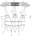
- Module 1 comprises from upstream to downstream in the direction of propagation of the light rays along the optical axis 15, three arrays S1, S2, S3 comprising primary sources 8 of light capable of emitting light rays, at least one associated primary optical system 4 to each matrix that transmits the light rays emitted by the primary sources of the matrix with which it is associated, and optical projection means 3 configured to project a light beam from the incident light rays transmitted by the primary optical systems 4.
- the optical module comprises three matrices of primary sources of light, it being understood that the minimum number of matrices is at least two matrices.
- the projection means 3 further form an optical projection system and may take the form of a single projection lens.
- the projection means could nevertheless be formed of the combination provided with several lenses, several reflectors, or a combination of one or more lenses and / or one or more reflectors.
- Each matrix S1, S2, S3 is arranged on a plane of its own: the matrix S1 is placed on the plane 21a, S2 on the plane 21b and S3 on the plane 21c.
- the way in which the planes are arranged relative to each other may vary.
- the planes of the matrices are confused.
- the planes of the dies are substantially parallel to each other.
- the planes of the arrays are arranged to allow the center of each array to be placed on a curved line; preferably, the curved line rests on a plane which comprises the optical axis of the projection means, and it may be regular, for example a circular arc 21d as illustrated in FIG. figure 8 .
- the dies are arranged in space so that their respective centers rest on a circular arc with a radius that can be between infinity (that is, a flat surface) and f / 5, where f is the value of the focal length of the overall system formed by the combination of one of the primary optical systems and the optical projection system.
- Each matrix therefore belongs to a plan of its own. It will be understood that the arrangement of the planes in space is not limited to the preceding examples; the only limit is that the primary optical system associated with each matrix can form a virtual image of the matrix upstream of the latter. The creation of virtual images is discussed below.
- the primary optical system 4 associated with each matrix has the function of transmitting light rays from the primary sources of light of the matrix so that, combined with the projection means, the beam projected outside the module, for example on the road, is homogeneous.
- the primary optical system 4 may be provided with one or more convergent optics.
- the primary optical systems 4 are simple convergent lenses.
- said one or more convergent optics may be convergent input micro-diopters.
- the input micro-diopters 5 have a convex surface, that is to say they are bulged outwards towards the sources 8. The surface could however be flat, plano-convex or concave -convex.
- An input micro-diopter 5 is advantageously disposed downstream of each light source 8, that is to say from each light-emitting diode or matrix of diodes of the matrix 2, as shown in FIG. figure 2 .
- the input micro-diopters 5 form virtual images 6 of the primary sources 8 of light, as shown in FIG. figure 2 .
- micro-diopter refers to diopters whose external dimensions are less than or equal to 5 times the dimensions of the primary source of light or the matrix of primary sources of associated light. They are usually in millimetric order of magnitude. For example, for a diode individual electro-luminescent light (LED) whose transmitting surface is 1 mm on the side, the dimensions of the associated diopter will be inscribed in a square of 5 mm maximum side. If the primary source is a matrix of LEDs, it is the dimensions of the matrix that will be considered. In addition, if the primary sources are all of the same size, it can be expected that all the micro-diopters have the same size.
- LED electro-luminescent light
- the dioptres associated with the sources at the edge of the matrix, in particular at the lateral ends to be of larger dimensions than the others in order to form a laterally and vertically elongated virtual image which will give a projected light pattern of moreover larger than the others, especially to produce an illumination of the sides of the road.
- the primary optical system 4 may furthermore comprise a single output diopter 9 for all the input micro-diopters 5.
- the output diopter 9 provides an optical correction of the beam transmitted to the projection lens 3.
- the correction serves in particular to to improve the optical efficiency of the device and to correct the optical aberrations of the system 4.
- the output diopter 9 has a substantially spherical dome shape. This shape deviates little the direction of the light rays of the beam coming from a source disposed on the optical axis 15, and which pass through the output diopter 9.
- the output diopter 9 may have a substantially spherical dome shape, or still an elongated shape, of cylindrical type, with a bifocal definition.
- the primary optical system 4 can be made of a single material, that is to say material.
- the input micro-diopters 5 and the output diopter 9 form the input and output faces of the same element, the primary optical system 4, which is similar to a complex lens.
- the primary optical system 4 may comprise an output micro-diopter 9 for each input micro-diopter 5.
- the primary optical system 4 then forms a set of bi-convex microlenses, each microlens being arranged in front of a primary source of light.
- the microlens do not allow correct the transmitted overall beam, as a primary optical system 4 provided with a single output diopter 9. This microlens has the advantage of providing a better homogeneity of the virtual images and less deformation of the images.
- the output dioptres 9 and the input micro-diopters 5 are part of a primary optical system 4 integrally.
- the primary optical system 4 comprises only one element.
- the primary optical system 4 provided with micro-diopters as convergent optics makes it possible to image a pixelated light source in which each virtual image created is an imaged pixel.
- each matrix S1, S2, S3 forms a single virtual image.
- the matrix may be a pixelated light source from which a virtual image is obtained, and this virtual image is composed of imaged pixels.
- all the imaged pixels of the matrix form the virtual image.
- the pixels imaged on the edges of two neighboring matrices overlap partially so that the virtual image of a matrix does not include any space (zones without light).
- the primary optical system 4 of each matrix thus makes it possible to form a virtual image 6 of the primary light sources 8 in order to obtain a homogeneous distribution of the beam, that is to say that the components of the light beam are correctly adjusted one by one. compared to the others, without dark bands and / or bright (in overcurrent) between them that would harm the comfort of driving.
- the virtual images 6 are formed upstream of the matrices S1, S2, S3 of primary sources 8 by the primary optical systems 4.
- the expression "a virtual image of the matrix is formed upstream of the latter" means that the rays formed in upstream of each primary optical system appear to come from an image at the back of each primary source. Virtual images therefore serve as new sources of light for the projection means.
- the virtual images 6 obtained are preferably enlarged, and the virtual images of a pair of matrices (20) associated overlap partially.
- a pair of associated matrices means two adjacent matrices, their adjacency being established with respect to a spacing zone between the two matrices.
- a pair of associated matrices means two matrices that one wishes to see, or that one considers, as abutments. Fencing of two matrices therefore corresponds to putting them side by side, preferably as close as possible, for the purpose for example of simulating a matrix that would be in one piece.
- a residual space is conserved between two successive adjacent matrices, this space being greater than the space between any two adjacent primary sources 8 disposed on the same matrix.
- the space between two successive joint matrices is strictly greater than the length of the electronic component forming each of the primary sources 8 of these matrices.
- the adjacent virtual images of two adjacent matrices overlap partially with one another: the partial overlap is reflected by an overlap of their respective projections by the projection means. More precisely, one or more images of the primary sources of two abutting matrices overlap. We can then talk about overlapping pixels.
- the virtual images are partially covered with a paraxial point of view, with a tolerancing margin to ensure the robustness with respect to the positioning accuracy of the light sources and vis-à-vis defects in the realization of the primary optical systems (for example the surfaces of the micro-diopters) .
- the invention therefore not only makes it possible to use standard components present on the market, but it also avoids the problems of thermal expansion occurring between the abutting components that carry the light sources.
- the overlay assures a robustness of the system vis-à-vis the tolerances of positioning of the virtual images, the tolerance of positioning of the images which itself depends on the positional tolerance of the primary sources, the positional tolerance and the fabrication of the primary optical systems.
- the virtual images 6 may be further away from the projection lens 3 with respect to the arrays of the primary light sources, which makes it possible to keep a compact optical module.
- the primary optical systems 4 are advantageously configured to form virtual images 6 on a single surface which is common for all the virtual images formed by the different primary optical systems.
- said single surface is used to create a virtual image formed from the set of virtual images, and this virtual image is continuous in particular because the virtual images of pairs of associated matrices overlap partially.
- the virtual virtual images partially overlap and create a single virtual image in which there is no non-illuminated area. In other words, there is no dark zone in the light beam emitted by the module according to the invention.
- the dimensions of the virtual images 6 are larger than the dimensions of the primary light sources 8.
- the enlargement of the size of the virtual images S'1, S'2 and S'3 allows a partial recovery of the virtual images of a pair of associated matrices.
- the matrices S1 and S2 form a pair of associated matrices because they are terraced.
- Their respective primary optical system in this example a simple convergent lens
- the two virtual images S'1 and S'2 are formed on the same surface 24a, 24b.
- the recovery is at the level of the S'4a brace.
- the matrices S2 and S3 form a pair of associated matrices because they are terraced, and their virtual images S'2 and S'3 are also formed on the plane 24a with a covering located at the brace S'4a.
- the single surface may be a plane 24a. It may also be a surface having a curvature, for example the surface 24b has a curvature such that any point of the surface admits the tangent plane.
- a surface curve makes it possible to correct aberrations created by the projection means that can be formed by the optical projection lens 3.
- the virtual image formed from the set of virtual images is continuous, that is to say that it does not include a dark area.
- the convex curvature and the material constituting each primary optical system is adapted to the dimensions of the matrix S1. , S2, S3 of primary sources 8, as well as the positioning of the primary optical system 4 relative to the matrix, so that the virtual virtual images overlap partially.
- the primary optical system it is possible to place the primary optical system almost in contact with the matrix with which it is associated.
- the distance between the primary optical system and the associated matrix is less than 1 mm, for example 0.5 mm.
- a matrix comprises at least two different light-emitting zones, which are individually addressable; a matrix therefore comprises at least two primary sources (8) of light capable of emitting light rays.
- the primary sources preferably form a primary source gate, i.e., the light sources are distributed over the die in a regular pattern, for example a checkerboard pattern.
- the figure 3 shows a multi-chip array of light-emitting diode-type light sources 8, each source 8 being individually addressable. Each source 8 is manufactured separately on an independent chip, which is mounted on a holding element 18, itself assembled to the other sources on a support 17.
- the figure 5 represents a second type of multi-chip matrix in which the light-emitting diodes are preassembled to each other on a common holding member disposed on a support 17.
- the Figures 6 and 7 illustrate single-chip matrices 20, in which the light sources 8 have an electrode in common.
- a diode has two electrodes 16, 19 in contact, a first point electrode 19 and a second surface electrode 16.
- the primary sources 8 are addressable individually by activating the first electrode 19, the second electrode being the same for all the sources 8 of the chip.
- the light sources 8 of the figure 7 have a second electrode 19 divided into a portion so as to have a second independent electrode 19 for each source 8, the first electrodes 16 being simultaneously activatable.
- the arrays may be based on a semiconductor light source comprising a plurality of submillimetric electroluminescent units, the units being distributed in different selectively activatable light areas.
- each of the submillimetric electroluminescent light units takes the form of a rod.
- the primary sources of light 8 are, for example, light-emitting diodes forming a network on a matrix, as represented for example on the figure 5 .
- a matrix of light-emitting diodes are known and commercially available.
- the primary optical systems 4 combine the light rays of the dies 20 to form a single beam having the same properties as if the dies of the device were perfectly butted.
- the figure 17 shows a schematic example of a front view of four matrices (S1 to S4) which are abutted in a same plane 21, and in which the distance between two adjacent matrices (S1-S2, S2-S3, S3-S4) is non-zero, greater than 20 micrometers and typically 1mm to 20mm or more, due to construction constraints related to the matrices.
- S1-S2, S2-S3, S3-S4 the distance between two adjacent matrices
- S1-S2, S2-S3, S3-S4 the distance between two adjacent matrices
- each plane 21a to 21d comprises two matrices.
- the two associated matrices S1-S5, S2-S6, S3-S7, S4-S8 are located on the same plane and are not abutted.
- Each matrix is associated with its primary optical system 4 (schematized by a circle).
- each plane 21a to 21d comprises two matrices, the two matrices located on the same plane being butted.
- the matrices arranged on the same plane are associated with the same primary optical system that they share, which makes it possible to lighten the device.
- Manage recovery means controlling one or more parameters of the recovery, for example its dimensions, its emittance ...
- Matrices with primary light sources may be of any shape.
- the dies in practice have a quadrilateral shape, preferably a regular quadrilateral such as a rectangle or a square; thus the virtual image produced will also have a quadrilateral shape.
- Virtual images formed on the single surface are partially covered by a paraxial point of view. More precisely, the overlap is made, for each association of two matrices, in at least one direction, and the width of the overlap is the measured distance of the overlap along the same direction.
- the figure 20 shows an example of recovery of two virtual images S'1 and S'2 produced for example by sources S1 and S2 of figures 1 , 8 , 17-19 .
- the two images are from rectangular shapes because the matrices of the light sources S1 and S2 are rectangular; for example, their primary sources form a grid.
- the two virtual images S'1 and S'2 are aligned in a first direction y, and the overlap (the shaded area on the figure 20 ) is made in the direction x for a width a.
- the figure 21 shows another example of recovery of four virtual images S'1 and S'2 produced for example by the sources S1, S2, S5, S6 of the figure 18 .
- the four images are rectangular in shape because the four matrices of the light sources are too.
- the two virtual images S'1 and S'2 are created by the pair of matrices S1 and S2 (S5 and S6) and are aligned in a first direction y, the covering being made according to the direction x for a given width a (b). It will be understood that the widths a and b are preferably equal in order to facilitate the management of overlaps.
- S1 and S5 also form a pair of associated matrices, and their virtual images S'1 and S'5 (S'2 and S'6) are this time aligned in the x direction and overlap according to the y direction for a cover width c (d).
- the widths c and d are preferably equal in order to facilitate the management of overlaps.
- a matrix can have more than one association; in this example, S1 is associated with two matrices S2 and S5.
- the associated matrices are pixelated light sources, which is for example the case with light-emitting diode arrays, or the case with a light matrix associated with primary optical system comprising input micro-diopters 5. And so, when the light sources are pixilated sources, the pixels of these sources are imaged and the set of imaged pixels form the virtual image of the matrix.
- p pixels of each virtual image contribute to partial recovery; p is a natural integer.
- Each pixel among the pixels may contribute in its entirety or partially to the recovery.
- the figure 22 illustrates these two cases. The figure 22 is similar to the figure 20 , except that the imaged pixels are represented.
- the pixel 26 of the virtual image S'2 contributes in its entirety to the recovery, while the pixel 27 of the virtual image S'1 contributes partially to the recovery.
- the two virtual images S'1 and S'2 have an equal number of pixels, respectively p 1i pixels for S'1 and p 2i S'2, which contribute to the recovery, the numbers p 1i and p 2i being integers natural. It is possible to envisage examples in which the numbers p 1i and p 2i are not equal, for example if the pixel density of the two virtual images is not equal.
- Overlay occurs when the adjacent virtual images have an overlap that at least partially involves one pixel of each virtual image.
- the recovery is performed, for each association of two matrices, in at least one direction; for example, at least one column of imaged pixels of each virtual image participates in the recovery.
- the width of the overlap involves at least two lines of imaged pixels of each virtual image to ensure that the covering is resilient to factors such as the thermal expansion that can occur between the components of the device, the misalignments of the position of a matrix and / or its primary optical system.
- two columns of pixels for each image S'1 and S'2 participate in the recovery.
- the number of imaged pixels of each virtual image depends on the configuration of the matrix. For example, for a resolution of the image pixels comprised in 0.05 ° and 0.2 °, the number of pixels p of a matrix which overlap with p pixels of another matrix is preferably greater than 10 pixels. that is, 10 or more columns of pixels of each matrix overlap each other. In general, it can be considered that a covering between 20 and 50 columns of pixels of each matrix ensures a very good robustness of the device.
- the emittance of the recovery must be substantially equal to that of the virtual image areas not participating in the recovery.
- the primary light sources of a pair of associated matrices are configured so that the sum of the emittances at a point of the partial recovery is substantially equal to the emittance at a point of one of the matrices not contributing to the recovery.
- the substantially equal expression means that the value of the emittance between the overlap and the other zones may vary by ⁇ 10%. Preferably, the variation is less than or equal to ⁇ 5%.
- each matrix comprises a grid of primary sources of light, as discussed with reference to the figures 3 , 5-7 , and each primary source of light is individually addressable. It is therefore possible to modify the individual luminous intensity of an imaged pixel by modifying the emittance of one or more primary sources of light of the matrix.
- a matrix has a quadrilateral shape, preferably a regular quadrilateral such as a rectangle or a square. It is then possible to control the luminous intensity of the primary sources contributing (or constituent) to illuminate a line of imaged pixels, said pixel line contributing to the partial recovery.
- each pixel p 1i imaged with a first virtual image contributing to the partial recovery is associated at one or more pixels p 2i imaged with a second virtual image contributing to the partial covering, so that the covering comprise one or more pairs of pixels ( p 1i , p 2i ), the light intensities of the pairs of pixels ( p 1i , p 2i ) being substantially equal.
- the pairs are firstly chosen so that the pixel pixels composing them overlap in priority entirely. It will be understood that the luminous intensity of a pair of pixels ( p 1i , p 2i ) is the sum of the luminous intensity of each pixel of said pair.
- the primary sources are LEDs
- the T on / T off duty cycle of the electrical current is controlled to obtain the desired average electrical intensity. This control is carried out as known in the art.
- the luminous intensities of the pairs of pixels ( p 1i , p 2i ) are substantially equal.
- the primary sources of light which contribute to the recovery - that is to say those which illuminate the imaged pixels of the overlay-can be configured so that their light intensity is proportional to their distance from the array to which they do not belong.
- the luminous intensity of the imaged pixel 27 of S'1 is larger than that of the image pixel 28 of S'1.
- the Figures 11 to 13 illustrate an example in which the matrices are identical so that it is possible to have a pair of imaged pixels - between an imaged pixel p 1i of a first virtual image contributing to the partial overlap and an image pixel p 2i of a second virtual image contributing to the partial recovery- in which a total recovery of the two pixels is possible.
- the figure 11 represents the intensities of the six imaged pixels of a first virtual image, for example S'1 on the figure 22 . These pixels belong to columns of pixels numbered p 1i with i between n-6 and n, n being the number of columns of pixels of the matrix S1 producing the virtual image S'1. These pixels p 1i are located on the same line of pixels of the virtual image S'1.
- the figure 12 represents the intensities of the six imaged pixels of a second virtual image, for example S'2 on the figure 22 . These pixels belong to columns of pixels numbered p 2i with i between 1 and 7. These pixels numbered p 2i are located on the same line of pixels of the virtual image S'2.
- the pixels of the first source S1 -the matrix S1 is located to the left of the source S2 and produces the virtual image S'1- are controlled in order to obtain a decrease of the emittance of a pixel column to the other while the pixels of the second source S2 - the matrix S2 is located to the right of S1 and produces the virtual image S'2- have an emittance that increases from one pixel column to another.
- the difference in emittance between two consecutive columns can be dictated by the ratio i / p, with p representing the number of columns participating in the recovery for a virtual image and i which represents the luminous intensity of the imaged pixels not contributing to the recovery.
- p representing the number of columns participating in the recovery for a virtual image
- i represents the luminous intensity of the imaged pixels not contributing to the recovery.
- the intensity of the pixels contributing to the recovery is decreasing, and it is increasing on the figure 12 .
- the emittance of the overlap is equal to that of the other zones of the virtual images.
- the figure 13 illustrative constant intensity distribution on both virtual images.
- pixel pixels p 1i and p 2i of a pair of pixels overlap substantially in their entirety in the example of Figures 11 to 13 . It is therefore understood that the primary light sources of a pair of associated matrices are configured so that the sum of the emittances at a point of the partial recovery is substantially equal to the emittance at a point of one of the matrices not contributing to the recovery.
- the sum of the luminous intensity of each pair of imaged pixels overlapping is substantially equal to the intensity of any of the imaged pixels not participating in the recovery; it being understood that it is considered that the two butted dies have, for their pixels not participating in the recovery, a similar emittance, that is to say very close or equal.
- the Figures 14 to 16 illustrate a case somewhat different from that illustrated on the Figures 11 to 13 since the pixels p 1i and p 2i of a matrix association overlap only partially.
- a partial recovery may result from a fault assembly of the device during its manufacture (for example following a bad calibration), or after its manufacture (for example following an impact).
- the intensity on the recovery zone is not constant since there is a shift 30 between the images of the pixel pixels of each pair p 1i p 2i of a pair of pixels.
- the number of pixels will be 20000 pixels for a resolution of 0.05 ° per pixel and 1000 pixels for a resolution of 0.2 ° per pixel.
- This resolution range for each imaged pixel corresponds to a spatial frequency of between 5 and 20 cycles per degree (cpd), and in this range of spatial frequency values there is a defect contrast below which the defect will not be visible.
- the modulation should preferably be between 1/50 and 1/20 inclusive.
- the number of pixels of each participating matrix overlap should preferably be between 20 and 50 pixels inclusive.
- the defect it is possible to make the defect invisible to the human eye by adjusting how the associated pixels overlap. If the offset is less than 1 pixel, i.e. if there is at least a partial overlap between two associated pixels (as shown in FIGS. Figures 14 to 16 ), the defect is then invisible for the human eye if the resolution of each imaged and associated pixel is between 0.05 ° and 0.2 °. As explained above, the number of pixel columns of each matrix involved in the recovery should preferably be in 20 and 50 columns inclusive.
- the defect can then be visible to the human eye.
- a correction can be made by modifying the luminous intensity of the imaged pixels of one and / or the other matrix, or by shifting the growth or decreasing luminous intensity of certain pixels if the dimension the matrix concerned is greater than the number of pixels that can be turned on; there are pixels in reserve on the matrix that can be used.
- an offset may be ignored because it has no influence that is perceptible to the human eye, or corrected by a correction operation in which the luminous intensity of the pixels involved in the recovery of the virtual images is reconfigured.
- This correction operation is easy to implement because it relies essentially on the control of the primary sources of the matrices, and does not require modifying the positioning of the constituent elements of the device according to the invention.
- the device according to the invention makes it possible to correct assembly defects of the device by reprogramming the pixels, that is to say without having to physically intervene on the elements included in the device.
- the figure 9 presents an example of a device similar to that discussed with reference to the figure 8 . It comprises three matrices S1, S2, S3 each provided with primary sources (8) of light which are capable of emitting light rays. Each matrix is disposed on a plane 21a, 21b, 21c which is specific to it. The plans 21a, 21b, 21c can be confused, or not; in this example, they are not.
- each matrix is associated with a primary optical system 4 which is disposed downstream of the matrix.
- Each primary optical system forms a first virtual image S'1, S'2, S'3 of the source with which it is associated, and each of the virtual images is formed upstream of the matrix corresponding to the virtual image.
- the virtual images S'1, S'2, S'3 do not overlap partially.
- the optical projection system may be a conventional lens - for example a revolving lens since the virtual images that are imaged already have the overlay so that the projected beam will also have the overlay.
- the optical projection system (3) that is responsible for ensuring the recovery of images from sources to infinity.
- the optical projection system comprises means forming, for each of the virtual images formed by a primary optical system 4, a second virtual image.
- a second virtual image S "1 of the first virtual image S'1 of the matrix S1 is created, and likewise for each of the matrices S2 and S3, the second virtual images S" 1, S "2, S” 3 are formed so that they overlap partially in the image formed by the optical projection system.
- the optical projection system of the figure 9 comprises means 3a, 3b, 3c which are each associated with one of the primary optical systems and which create the second virtual images S "1, S" 2, S "3.
- means 3a, 3b, 3c, which are at the input of the projection optical system 3, may comprise a prism which is associated with each matrix. Each prism contributes to re-phase the so-called first virtual images created by the primary optical systems.
- the optical projection system of the figure 9 further comprises a 3d lens which forms the image of said second virtual images.
- the 3d lens may be a lens similar to that of the example of the Figure 8 .
- the means 3a, 3b, 3c and the lens 3d can form a single lens, as shown schematically on the figure 9 .
- the means 3a, 3b, 3c and the lens 3d are distinct and are then arranged so that the output lens 3d of the projection system can image at infinity said second virtual images.
- the means 3a, 3b, 3c constitute a lens and 3d constitutes a lens.
- the means 3a, 3b, 3c constitute a diopter, and 3d also.
- the overlay is created at the input of the projection optical device.
- the figure 10 presents an example of a device similar to that discussed with reference to the figure 9 in that the virtual images S'1, S'2, S'3 do not partially overlap.
- the optical projection system comprises two lenses 3e, 3f, which can be made of material.
- the two lenses 3e and 3f of the projection system are arranged so that they create images S "1, S" 2, S "3, corresponding to the virtual images S'1, S'2, S'3, which overlap is thus created at the output of the optical projection system.
Applications Claiming Priority (1)
| Application Number | Priority Date | Filing Date | Title |
|---|---|---|---|
| FR1750412A FR3061965B1 (fr) | 2017-01-19 | 2017-01-19 | Dispositif de projection d’un faisceau lumineux pixelise, projecteur muni d’un tel dispositif |
Publications (2)
| Publication Number | Publication Date |
|---|---|
| EP3351990A1 true EP3351990A1 (de) | 2018-07-25 |
| EP3351990B1 EP3351990B1 (de) | 2020-03-25 |
Family
ID=58707713
Family Applications (1)
| Application Number | Title | Priority Date | Filing Date |
|---|---|---|---|
| EP17207778.6A Active EP3351990B1 (de) | 2017-01-19 | 2017-12-15 | Vorrichtung zur projektion eines verpixelten lichtstrahls, und mit einer solchen vorrichtung ausgestatteter scheinwerfer |
Country Status (6)
| Country | Link |
|---|---|
| US (1) | US10527246B2 (de) |
| EP (1) | EP3351990B1 (de) |
| JP (2) | JP7199810B2 (de) |
| KR (1) | KR102583981B1 (de) |
| CN (1) | CN108333855B (de) |
| FR (1) | FR3061965B1 (de) |
Families Citing this family (5)
| Publication number | Priority date | Publication date | Assignee | Title |
|---|---|---|---|---|
| FR3061965B1 (fr) * | 2017-01-19 | 2022-08-12 | Valeo Vision | Dispositif de projection d’un faisceau lumineux pixelise, projecteur muni d’un tel dispositif |
| FR3084440B1 (fr) * | 2018-07-30 | 2021-01-15 | Valeo Vision | Module lumineux de vehicule automobile apte a generer un faisceau lumineux avec au moins une rangee d'unites d'illumination |
| US11774837B2 (en) * | 2019-01-10 | 2023-10-03 | Osram Gmbh | Image displaying device and method for displaying an image on a screen |
| JP2020189608A (ja) * | 2019-05-24 | 2020-11-26 | スタンレー電気株式会社 | 車両用灯具 |
| EP3876021B1 (de) * | 2020-03-05 | 2023-12-06 | Lumileds LLC | Mikrooptik für mikro-led-projektionseinheit |
Citations (3)
| Publication number | Priority date | Publication date | Assignee | Title |
|---|---|---|---|---|
| EP2357399A1 (de) * | 2010-02-16 | 2011-08-17 | Koito Manufacturing Co., Ltd. | Optische Einheit |
| US20150241009A1 (en) * | 2014-02-25 | 2015-08-27 | Automotive Lighting Reutlingen Gmbh | Motor vehicle headlamp |
| DE102014210500A1 (de) * | 2014-06-03 | 2015-12-03 | Osram Gmbh | Optik für eine Fahrzeug-Beleuchtungseinrichtung |
Family Cites Families (8)
| Publication number | Priority date | Publication date | Assignee | Title |
|---|---|---|---|---|
| DE102005041234A1 (de) * | 2005-08-31 | 2007-03-01 | Hella Kgaa Hueck & Co. | Scheinwerfer für Fahrzeuge |
| JP4708285B2 (ja) | 2006-08-04 | 2011-06-22 | トヨタ自動車株式会社 | 車両用ヘッドランプ |
| EP2068068B1 (de) * | 2007-12-07 | 2013-11-20 | Stanley Electric Co., Ltd. | Fahrzeugscheinwerfer |
| JP5823211B2 (ja) | 2011-09-01 | 2015-11-25 | 株式会社小糸製作所 | 車両用前照灯装置 |
| DE102014206594A1 (de) * | 2014-04-04 | 2015-10-08 | Bayerische Motoren Werke Aktiengesellschaft | Beleuchtungsvorrichtung für ein Kraftfahrzeug |
| JP2017004661A (ja) | 2015-06-08 | 2017-01-05 | スタンレー電気株式会社 | 車両用灯具 |
| TWI607179B (zh) * | 2016-11-30 | 2017-12-01 | 隆達電子股份有限公司 | 透鏡陣列、使用透鏡陣列的車燈透鏡組及使用車燈透鏡組的車燈總成 |
| FR3061965B1 (fr) * | 2017-01-19 | 2022-08-12 | Valeo Vision | Dispositif de projection d’un faisceau lumineux pixelise, projecteur muni d’un tel dispositif |
-
2017
- 2017-01-19 FR FR1750412A patent/FR3061965B1/fr active Active
- 2017-12-15 EP EP17207778.6A patent/EP3351990B1/de active Active
-
2018
- 2018-01-09 CN CN201810018351.3A patent/CN108333855B/zh active Active
- 2018-01-17 KR KR1020180006153A patent/KR102583981B1/ko active IP Right Grant
- 2018-01-18 JP JP2018006581A patent/JP7199810B2/ja active Active
- 2018-01-18 US US15/874,267 patent/US10527246B2/en active Active
-
2022
- 2022-09-30 JP JP2022158815A patent/JP2022188167A/ja not_active Withdrawn
Patent Citations (3)
| Publication number | Priority date | Publication date | Assignee | Title |
|---|---|---|---|---|
| EP2357399A1 (de) * | 2010-02-16 | 2011-08-17 | Koito Manufacturing Co., Ltd. | Optische Einheit |
| US20150241009A1 (en) * | 2014-02-25 | 2015-08-27 | Automotive Lighting Reutlingen Gmbh | Motor vehicle headlamp |
| DE102014210500A1 (de) * | 2014-06-03 | 2015-12-03 | Osram Gmbh | Optik für eine Fahrzeug-Beleuchtungseinrichtung |
Also Published As
| Publication number | Publication date |
|---|---|
| KR102583981B1 (ko) | 2023-09-27 |
| US20180202624A1 (en) | 2018-07-19 |
| CN108333855A (zh) | 2018-07-27 |
| KR20180085691A (ko) | 2018-07-27 |
| EP3351990B1 (de) | 2020-03-25 |
| JP2018116934A (ja) | 2018-07-26 |
| FR3061965B1 (fr) | 2022-08-12 |
| US10527246B2 (en) | 2020-01-07 |
| FR3061965A1 (fr) | 2018-07-20 |
| CN108333855B (zh) | 2022-03-04 |
| JP7199810B2 (ja) | 2023-01-06 |
| JP2022188167A (ja) | 2022-12-20 |
Similar Documents
| Publication | Publication Date | Title |
|---|---|---|
| EP3351990B1 (de) | Vorrichtung zur projektion eines verpixelten lichtstrahls, und mit einer solchen vorrichtung ausgestatteter scheinwerfer | |
| EP3208529B1 (de) | Vorrichtung zur projektion eines lichtstrahls, die mit einer matrix von lichtquellen ausgestattet ist, leuchtmodul und kfz-scheinwerfer mit einer solchen vorrichtung | |
| EP3208530A1 (de) | Vorrichtung zur projektion eines lichtstrahls, die mit matrix von lichtquellen ausgestattet ist, leuchtmodul und kfz-scheinwerfer mit einer solchen vorrichtung | |
| EP3147557B1 (de) | Primäres optisches element für kraftfahrzeugsbeleuchtungsmodul | |
| EP3517827B1 (de) | Leuchtmodul, das ein primäres optisches modul umfasst, das mit zwei formgebungsmatten ausgestattet ist | |
| FR3055980B1 (fr) | Systeme optique pour faisceau lumineux pixelise | |
| EP1762776A1 (de) | Verfahren zur Herstellung eines Moduls eines Kraftfahrzeugscheinwerfers | |
| EP3604904B1 (de) | Lichtmodul, das eine matrix von lichtquellen und ein bifokales optisches system umfasst | |
| FR3041073A1 (fr) | Dispositif de projection de faisceau lumineux a ecran digital et projecteur muni d’un tel dispositif | |
| FR3065785A1 (fr) | Lentille de projection pour projecteur de vehicule automobile | |
| FR3062217A1 (fr) | Aboutage de sources lumineuses pixelisees | |
| EP3030830B1 (de) | Signalisierungs- und/oder beleuchtungsvorrichtung für kraftfahrzeuge | |
| EP3453946A1 (de) | Leuchtmodul für kraftfahrzeug, und beleuchtungs- und/oder signalisierungsvorrichtung, die mit einem solchen modul ausgestattet ist | |
| EP3511608B1 (de) | Optisches modul für ein kraftfahrzeug | |
| WO2020064964A1 (fr) | Système optique de projection et module lumineux pour véhicule | |
| EP3502550A1 (de) | Segmentierter lichtstrahl, der beleuchtungsfunktionen erfüllt | |
| EP2853804B1 (de) | Beleuchtungs- und/oder signalisierungsmodul mit mehreren drehbaren optischen systemen | |
| WO2023030808A1 (fr) | Module lumineux pour vehicule automobile | |
| FR2898662A1 (fr) | Procede de construction d'un module de projecteur lumineux pour vehicule automobile, module et projecteur | |
| WO2023006673A1 (fr) | Module lumineux pour phare de vehicule | |
| WO2024094529A1 (fr) | Dispositif d'éclairage | |
| WO2024061970A1 (fr) | Module lumineux | |
| FR3086032A1 (fr) | Systeme d'eclairage pour vehicule | |
| FR3074256A1 (fr) | Dispositif optique de projection de faisceau lumineux segmente muni d'un systeme optique de formation de segments lumineux. | |
| FR3084724A1 (fr) | Module lumineux a quatre parties de guidage |
Legal Events
| Date | Code | Title | Description |
|---|---|---|---|
| PUAI | Public reference made under article 153(3) epc to a published international application that has entered the european phase |
Free format text: ORIGINAL CODE: 0009012 |
|
| STAA | Information on the status of an ep patent application or granted ep patent |
Free format text: STATUS: THE APPLICATION HAS BEEN PUBLISHED |
|
| AK | Designated contracting states |
Kind code of ref document: A1 Designated state(s): AL AT BE BG CH CY CZ DE DK EE ES FI FR GB GR HR HU IE IS IT LI LT LU LV MC MK MT NL NO PL PT RO RS SE SI SK SM TR |
|
| AX | Request for extension of the european patent |
Extension state: BA ME |
|
| STAA | Information on the status of an ep patent application or granted ep patent |
Free format text: STATUS: REQUEST FOR EXAMINATION WAS MADE |
|
| 17P | Request for examination filed |
Effective date: 20190123 |
|
| RBV | Designated contracting states (corrected) |
Designated state(s): AL AT BE BG CH CY CZ DE DK EE ES FI FR GB GR HR HU IE IS IT LI LT LU LV MC MK MT NL NO PL PT RO RS SE SI SK SM TR |
|
| GRAP | Despatch of communication of intention to grant a patent |
Free format text: ORIGINAL CODE: EPIDOSNIGR1 |
|
| STAA | Information on the status of an ep patent application or granted ep patent |
Free format text: STATUS: GRANT OF PATENT IS INTENDED |
|
| INTG | Intention to grant announced |
Effective date: 20191106 |
|
| GRAS | Grant fee paid |
Free format text: ORIGINAL CODE: EPIDOSNIGR3 |
|
| GRAA | (expected) grant |
Free format text: ORIGINAL CODE: 0009210 |
|
| STAA | Information on the status of an ep patent application or granted ep patent |
Free format text: STATUS: THE PATENT HAS BEEN GRANTED |
|
| AK | Designated contracting states |
Kind code of ref document: B1 Designated state(s): AL AT BE BG CH CY CZ DE DK EE ES FI FR GB GR HR HU IE IS IT LI LT LU LV MC MK MT NL NO PL PT RO RS SE SI SK SM TR |
|
| REG | Reference to a national code |
Ref country code: GB Ref legal event code: FG4D Free format text: NOT ENGLISH |
|
| REG | Reference to a national code |
Ref country code: AT Ref legal event code: REF Ref document number: 1249217 Country of ref document: AT Kind code of ref document: T Effective date: 20200415 Ref country code: IE Ref legal event code: FG4D Free format text: LANGUAGE OF EP DOCUMENT: FRENCH |
|
| REG | Reference to a national code |
Ref country code: DE Ref legal event code: R096 Ref document number: 602017013567 Country of ref document: DE |
|
| PG25 | Lapsed in a contracting state [announced via postgrant information from national office to epo] |
Ref country code: FI Free format text: LAPSE BECAUSE OF FAILURE TO SUBMIT A TRANSLATION OF THE DESCRIPTION OR TO PAY THE FEE WITHIN THE PRESCRIBED TIME-LIMIT Effective date: 20200325 Ref country code: NO Free format text: LAPSE BECAUSE OF FAILURE TO SUBMIT A TRANSLATION OF THE DESCRIPTION OR TO PAY THE FEE WITHIN THE PRESCRIBED TIME-LIMIT Effective date: 20200625 Ref country code: RS Free format text: LAPSE BECAUSE OF FAILURE TO SUBMIT A TRANSLATION OF THE DESCRIPTION OR TO PAY THE FEE WITHIN THE PRESCRIBED TIME-LIMIT Effective date: 20200325 |
|
| PG25 | Lapsed in a contracting state [announced via postgrant information from national office to epo] |
Ref country code: BG Free format text: LAPSE BECAUSE OF FAILURE TO SUBMIT A TRANSLATION OF THE DESCRIPTION OR TO PAY THE FEE WITHIN THE PRESCRIBED TIME-LIMIT Effective date: 20200625 Ref country code: HR Free format text: LAPSE BECAUSE OF FAILURE TO SUBMIT A TRANSLATION OF THE DESCRIPTION OR TO PAY THE FEE WITHIN THE PRESCRIBED TIME-LIMIT Effective date: 20200325 Ref country code: GR Free format text: LAPSE BECAUSE OF FAILURE TO SUBMIT A TRANSLATION OF THE DESCRIPTION OR TO PAY THE FEE WITHIN THE PRESCRIBED TIME-LIMIT Effective date: 20200626 Ref country code: SE Free format text: LAPSE BECAUSE OF FAILURE TO SUBMIT A TRANSLATION OF THE DESCRIPTION OR TO PAY THE FEE WITHIN THE PRESCRIBED TIME-LIMIT Effective date: 20200325 Ref country code: LV Free format text: LAPSE BECAUSE OF FAILURE TO SUBMIT A TRANSLATION OF THE DESCRIPTION OR TO PAY THE FEE WITHIN THE PRESCRIBED TIME-LIMIT Effective date: 20200325 |
|
| REG | Reference to a national code |
Ref country code: NL Ref legal event code: MP Effective date: 20200325 |
|
| REG | Reference to a national code |
Ref country code: LT Ref legal event code: MG4D |
|
| PG25 | Lapsed in a contracting state [announced via postgrant information from national office to epo] |
Ref country code: NL Free format text: LAPSE BECAUSE OF FAILURE TO SUBMIT A TRANSLATION OF THE DESCRIPTION OR TO PAY THE FEE WITHIN THE PRESCRIBED TIME-LIMIT Effective date: 20200325 |
|
| PG25 | Lapsed in a contracting state [announced via postgrant information from national office to epo] |
Ref country code: SM Free format text: LAPSE BECAUSE OF FAILURE TO SUBMIT A TRANSLATION OF THE DESCRIPTION OR TO PAY THE FEE WITHIN THE PRESCRIBED TIME-LIMIT Effective date: 20200325 Ref country code: EE Free format text: LAPSE BECAUSE OF FAILURE TO SUBMIT A TRANSLATION OF THE DESCRIPTION OR TO PAY THE FEE WITHIN THE PRESCRIBED TIME-LIMIT Effective date: 20200325 Ref country code: PT Free format text: LAPSE BECAUSE OF FAILURE TO SUBMIT A TRANSLATION OF THE DESCRIPTION OR TO PAY THE FEE WITHIN THE PRESCRIBED TIME-LIMIT Effective date: 20200818 Ref country code: CZ Free format text: LAPSE BECAUSE OF FAILURE TO SUBMIT A TRANSLATION OF THE DESCRIPTION OR TO PAY THE FEE WITHIN THE PRESCRIBED TIME-LIMIT Effective date: 20200325 Ref country code: LT Free format text: LAPSE BECAUSE OF FAILURE TO SUBMIT A TRANSLATION OF THE DESCRIPTION OR TO PAY THE FEE WITHIN THE PRESCRIBED TIME-LIMIT Effective date: 20200325 Ref country code: IS Free format text: LAPSE BECAUSE OF FAILURE TO SUBMIT A TRANSLATION OF THE DESCRIPTION OR TO PAY THE FEE WITHIN THE PRESCRIBED TIME-LIMIT Effective date: 20200725 Ref country code: RO Free format text: LAPSE BECAUSE OF FAILURE TO SUBMIT A TRANSLATION OF THE DESCRIPTION OR TO PAY THE FEE WITHIN THE PRESCRIBED TIME-LIMIT Effective date: 20200325 Ref country code: SK Free format text: LAPSE BECAUSE OF FAILURE TO SUBMIT A TRANSLATION OF THE DESCRIPTION OR TO PAY THE FEE WITHIN THE PRESCRIBED TIME-LIMIT Effective date: 20200325 |
|
| REG | Reference to a national code |
Ref country code: AT Ref legal event code: MK05 Ref document number: 1249217 Country of ref document: AT Kind code of ref document: T Effective date: 20200325 |
|
| REG | Reference to a national code |
Ref country code: DE Ref legal event code: R097 Ref document number: 602017013567 Country of ref document: DE |
|
| PG25 | Lapsed in a contracting state [announced via postgrant information from national office to epo] |
Ref country code: DK Free format text: LAPSE BECAUSE OF FAILURE TO SUBMIT A TRANSLATION OF THE DESCRIPTION OR TO PAY THE FEE WITHIN THE PRESCRIBED TIME-LIMIT Effective date: 20200325 Ref country code: IT Free format text: LAPSE BECAUSE OF FAILURE TO SUBMIT A TRANSLATION OF THE DESCRIPTION OR TO PAY THE FEE WITHIN THE PRESCRIBED TIME-LIMIT Effective date: 20200325 Ref country code: AT Free format text: LAPSE BECAUSE OF FAILURE TO SUBMIT A TRANSLATION OF THE DESCRIPTION OR TO PAY THE FEE WITHIN THE PRESCRIBED TIME-LIMIT Effective date: 20200325 Ref country code: ES Free format text: LAPSE BECAUSE OF FAILURE TO SUBMIT A TRANSLATION OF THE DESCRIPTION OR TO PAY THE FEE WITHIN THE PRESCRIBED TIME-LIMIT Effective date: 20200325 |
|
| PLBE | No opposition filed within time limit |
Free format text: ORIGINAL CODE: 0009261 |
|
| STAA | Information on the status of an ep patent application or granted ep patent |
Free format text: STATUS: NO OPPOSITION FILED WITHIN TIME LIMIT |
|
| PG25 | Lapsed in a contracting state [announced via postgrant information from national office to epo] |
Ref country code: PL Free format text: LAPSE BECAUSE OF FAILURE TO SUBMIT A TRANSLATION OF THE DESCRIPTION OR TO PAY THE FEE WITHIN THE PRESCRIBED TIME-LIMIT Effective date: 20200325 |
|
| 26N | No opposition filed |
Effective date: 20210112 |
|
| PG25 | Lapsed in a contracting state [announced via postgrant information from national office to epo] |
Ref country code: SI Free format text: LAPSE BECAUSE OF FAILURE TO SUBMIT A TRANSLATION OF THE DESCRIPTION OR TO PAY THE FEE WITHIN THE PRESCRIBED TIME-LIMIT Effective date: 20200325 |
|
| REG | Reference to a national code |
Ref country code: CH Ref legal event code: PL |
|
| PG25 | Lapsed in a contracting state [announced via postgrant information from national office to epo] |
Ref country code: MC Free format text: LAPSE BECAUSE OF FAILURE TO SUBMIT A TRANSLATION OF THE DESCRIPTION OR TO PAY THE FEE WITHIN THE PRESCRIBED TIME-LIMIT Effective date: 20200325 |
|
| REG | Reference to a national code |
Ref country code: BE Ref legal event code: MM Effective date: 20201231 |
|
| PG25 | Lapsed in a contracting state [announced via postgrant information from national office to epo] |
Ref country code: IE Free format text: LAPSE BECAUSE OF NON-PAYMENT OF DUE FEES Effective date: 20201215 Ref country code: LU Free format text: LAPSE BECAUSE OF NON-PAYMENT OF DUE FEES Effective date: 20201215 |
|
| PG25 | Lapsed in a contracting state [announced via postgrant information from national office to epo] |
Ref country code: LI Free format text: LAPSE BECAUSE OF NON-PAYMENT OF DUE FEES Effective date: 20201231 Ref country code: CH Free format text: LAPSE BECAUSE OF NON-PAYMENT OF DUE FEES Effective date: 20201231 |
|
| PG25 | Lapsed in a contracting state [announced via postgrant information from national office to epo] |
Ref country code: TR Free format text: LAPSE BECAUSE OF FAILURE TO SUBMIT A TRANSLATION OF THE DESCRIPTION OR TO PAY THE FEE WITHIN THE PRESCRIBED TIME-LIMIT Effective date: 20200325 Ref country code: MT Free format text: LAPSE BECAUSE OF FAILURE TO SUBMIT A TRANSLATION OF THE DESCRIPTION OR TO PAY THE FEE WITHIN THE PRESCRIBED TIME-LIMIT Effective date: 20200325 Ref country code: CY Free format text: LAPSE BECAUSE OF FAILURE TO SUBMIT A TRANSLATION OF THE DESCRIPTION OR TO PAY THE FEE WITHIN THE PRESCRIBED TIME-LIMIT Effective date: 20200325 |
|
| PG25 | Lapsed in a contracting state [announced via postgrant information from national office to epo] |
Ref country code: MK Free format text: LAPSE BECAUSE OF FAILURE TO SUBMIT A TRANSLATION OF THE DESCRIPTION OR TO PAY THE FEE WITHIN THE PRESCRIBED TIME-LIMIT Effective date: 20200325 Ref country code: AL Free format text: LAPSE BECAUSE OF FAILURE TO SUBMIT A TRANSLATION OF THE DESCRIPTION OR TO PAY THE FEE WITHIN THE PRESCRIBED TIME-LIMIT Effective date: 20200325 |
|
| PG25 | Lapsed in a contracting state [announced via postgrant information from national office to epo] |
Ref country code: BE Free format text: LAPSE BECAUSE OF NON-PAYMENT OF DUE FEES Effective date: 20201231 |
|
| GBPC | Gb: european patent ceased through non-payment of renewal fee |
Effective date: 20211215 |
|
| PG25 | Lapsed in a contracting state [announced via postgrant information from national office to epo] |
Ref country code: GB Free format text: LAPSE BECAUSE OF NON-PAYMENT OF DUE FEES Effective date: 20211215 |
|
| P01 | Opt-out of the competence of the unified patent court (upc) registered |
Effective date: 20230528 |
|
| PGFP | Annual fee paid to national office [announced via postgrant information from national office to epo] |
Ref country code: FR Payment date: 20231220 Year of fee payment: 7 Ref country code: DE Payment date: 20231208 Year of fee payment: 7 |