EP3351769B2 - Gasturbinenmotor mit zwei achsabtiebswellen sowie betriebsverfahren - Google Patents
Gasturbinenmotor mit zwei achsabtiebswellen sowie betriebsverfahren Download PDFInfo
- Publication number
- EP3351769B2 EP3351769B2 EP18152645.0A EP18152645A EP3351769B2 EP 3351769 B2 EP3351769 B2 EP 3351769B2 EP 18152645 A EP18152645 A EP 18152645A EP 3351769 B2 EP3351769 B2 EP 3351769B2
- Authority
- EP
- European Patent Office
- Prior art keywords
- towershaft
- starter generator
- generator assembly
- gas turbine
- speed
- Prior art date
- Legal status (The legal status is an assumption and is not a legal conclusion. Google has not performed a legal analysis and makes no representation as to the accuracy of the status listed.)
- Active
Links
Images


Classifications
-
- F—MECHANICAL ENGINEERING; LIGHTING; HEATING; WEAPONS; BLASTING
- F02—COMBUSTION ENGINES; HOT-GAS OR COMBUSTION-PRODUCT ENGINE PLANTS
- F02C—GAS-TURBINE PLANTS; AIR INTAKES FOR JET-PROPULSION PLANTS; CONTROLLING FUEL SUPPLY IN AIR-BREATHING JET-PROPULSION PLANTS
- F02C7/00—Features, components parts, details or accessories, not provided for in, or of interest apart form groups F02C1/00 - F02C6/00; Air intakes for jet-propulsion plants
- F02C7/32—Arrangement, mounting, or driving, of auxiliaries
-
- F—MECHANICAL ENGINEERING; LIGHTING; HEATING; WEAPONS; BLASTING
- F01—MACHINES OR ENGINES IN GENERAL; ENGINE PLANTS IN GENERAL; STEAM ENGINES
- F01D—NON-POSITIVE DISPLACEMENT MACHINES OR ENGINES, e.g. STEAM TURBINES
- F01D15/00—Adaptations of machines or engines for special use; Combinations of engines with devices driven thereby
- F01D15/10—Adaptations for driving, or combinations with, electric generators
-
- F—MECHANICAL ENGINEERING; LIGHTING; HEATING; WEAPONS; BLASTING
- F01—MACHINES OR ENGINES IN GENERAL; ENGINE PLANTS IN GENERAL; STEAM ENGINES
- F01D—NON-POSITIVE DISPLACEMENT MACHINES OR ENGINES, e.g. STEAM TURBINES
- F01D15/00—Adaptations of machines or engines for special use; Combinations of engines with devices driven thereby
- F01D15/12—Combinations with mechanical gearing
-
- F—MECHANICAL ENGINEERING; LIGHTING; HEATING; WEAPONS; BLASTING
- F01—MACHINES OR ENGINES IN GENERAL; ENGINE PLANTS IN GENERAL; STEAM ENGINES
- F01D—NON-POSITIVE DISPLACEMENT MACHINES OR ENGINES, e.g. STEAM TURBINES
- F01D25/00—Component parts, details, or accessories, not provided for in, or of interest apart from, other groups
- F01D25/08—Cooling; Heating; Heat-insulation
- F01D25/12—Cooling
-
- F—MECHANICAL ENGINEERING; LIGHTING; HEATING; WEAPONS; BLASTING
- F02—COMBUSTION ENGINES; HOT-GAS OR COMBUSTION-PRODUCT ENGINE PLANTS
- F02C—GAS-TURBINE PLANTS; AIR INTAKES FOR JET-PROPULSION PLANTS; CONTROLLING FUEL SUPPLY IN AIR-BREATHING JET-PROPULSION PLANTS
- F02C3/00—Gas-turbine plants characterised by the use of combustion products as the working fluid
- F02C3/04—Gas-turbine plants characterised by the use of combustion products as the working fluid having a turbine driving a compressor
- F02C3/06—Gas-turbine plants characterised by the use of combustion products as the working fluid having a turbine driving a compressor the compressor comprising only axial stages
-
- F—MECHANICAL ENGINEERING; LIGHTING; HEATING; WEAPONS; BLASTING
- F02—COMBUSTION ENGINES; HOT-GAS OR COMBUSTION-PRODUCT ENGINE PLANTS
- F02C—GAS-TURBINE PLANTS; AIR INTAKES FOR JET-PROPULSION PLANTS; CONTROLLING FUEL SUPPLY IN AIR-BREATHING JET-PROPULSION PLANTS
- F02C7/00—Features, components parts, details or accessories, not provided for in, or of interest apart form groups F02C1/00 - F02C6/00; Air intakes for jet-propulsion plants
- F02C7/12—Cooling of plants
- F02C7/16—Cooling of plants characterised by cooling medium
- F02C7/18—Cooling of plants characterised by cooling medium the medium being gaseous, e.g. air
- F02C7/185—Cooling means for reducing the temperature of the cooling air or gas
-
- F—MECHANICAL ENGINEERING; LIGHTING; HEATING; WEAPONS; BLASTING
- F02—COMBUSTION ENGINES; HOT-GAS OR COMBUSTION-PRODUCT ENGINE PLANTS
- F02C—GAS-TURBINE PLANTS; AIR INTAKES FOR JET-PROPULSION PLANTS; CONTROLLING FUEL SUPPLY IN AIR-BREATHING JET-PROPULSION PLANTS
- F02C7/00—Features, components parts, details or accessories, not provided for in, or of interest apart form groups F02C1/00 - F02C6/00; Air intakes for jet-propulsion plants
- F02C7/26—Starting; Ignition
- F02C7/268—Starting drives for the rotor, acting directly on the rotor of the gas turbine to be started
- F02C7/275—Mechanical drives
-
- F—MECHANICAL ENGINEERING; LIGHTING; HEATING; WEAPONS; BLASTING
- F02—COMBUSTION ENGINES; HOT-GAS OR COMBUSTION-PRODUCT ENGINE PLANTS
- F02C—GAS-TURBINE PLANTS; AIR INTAKES FOR JET-PROPULSION PLANTS; CONTROLLING FUEL SUPPLY IN AIR-BREATHING JET-PROPULSION PLANTS
- F02C7/00—Features, components parts, details or accessories, not provided for in, or of interest apart form groups F02C1/00 - F02C6/00; Air intakes for jet-propulsion plants
- F02C7/36—Power transmission arrangements between the different shafts of the gas turbine plant, or between the gas-turbine plant and the power user
-
- F—MECHANICAL ENGINEERING; LIGHTING; HEATING; WEAPONS; BLASTING
- F16—ENGINEERING ELEMENTS AND UNITS; GENERAL MEASURES FOR PRODUCING AND MAINTAINING EFFECTIVE FUNCTIONING OF MACHINES OR INSTALLATIONS; THERMAL INSULATION IN GENERAL
- F16H—GEARING
- F16H1/00—Toothed gearings for conveying rotary motion
- F16H1/02—Toothed gearings for conveying rotary motion without gears having orbital motion
- F16H1/20—Toothed gearings for conveying rotary motion without gears having orbital motion involving more than two intermeshing members
- F16H1/22—Toothed gearings for conveying rotary motion without gears having orbital motion involving more than two intermeshing members with a plurality of driving or driven shafts; with arrangements for dividing torque between two or more intermediate shafts
- F16H1/222—Toothed gearings for conveying rotary motion without gears having orbital motion involving more than two intermeshing members with a plurality of driving or driven shafts; with arrangements for dividing torque between two or more intermediate shafts with non-parallel axes
-
- H—ELECTRICITY
- H02—GENERATION; CONVERSION OR DISTRIBUTION OF ELECTRIC POWER
- H02K—DYNAMO-ELECTRIC MACHINES
- H02K7/00—Arrangements for handling mechanical energy structurally associated with dynamo-electric machines, e.g. structural association with mechanical driving motors or auxiliary dynamo-electric machines
- H02K7/10—Structural association with clutches, brakes, gears, pulleys or mechanical starters
- H02K7/116—Structural association with clutches, brakes, gears, pulleys or mechanical starters with gears
-
- H—ELECTRICITY
- H02—GENERATION; CONVERSION OR DISTRIBUTION OF ELECTRIC POWER
- H02K—DYNAMO-ELECTRIC MACHINES
- H02K7/00—Arrangements for handling mechanical energy structurally associated with dynamo-electric machines, e.g. structural association with mechanical driving motors or auxiliary dynamo-electric machines
- H02K7/18—Structural association of electric generators with mechanical driving motors, e.g. with turbines
- H02K7/1807—Rotary generators
- H02K7/1823—Rotary generators structurally associated with turbines or similar engines
-
- F—MECHANICAL ENGINEERING; LIGHTING; HEATING; WEAPONS; BLASTING
- F05—INDEXING SCHEMES RELATING TO ENGINES OR PUMPS IN VARIOUS SUBCLASSES OF CLASSES F01-F04
- F05D—INDEXING SCHEME FOR ASPECTS RELATING TO NON-POSITIVE-DISPLACEMENT MACHINES OR ENGINES, GAS-TURBINES OR JET-PROPULSION PLANTS
- F05D2220/00—Application
- F05D2220/30—Application in turbines
- F05D2220/32—Application in turbines in gas turbines
-
- F—MECHANICAL ENGINEERING; LIGHTING; HEATING; WEAPONS; BLASTING
- F05—INDEXING SCHEMES RELATING TO ENGINES OR PUMPS IN VARIOUS SUBCLASSES OF CLASSES F01-F04
- F05D—INDEXING SCHEME FOR ASPECTS RELATING TO NON-POSITIVE-DISPLACEMENT MACHINES OR ENGINES, GAS-TURBINES OR JET-PROPULSION PLANTS
- F05D2260/00—Function
- F05D2260/40—Transmission of power
- F05D2260/403—Transmission of power through the shape of the drive components
- F05D2260/4031—Transmission of power through the shape of the drive components as in toothed gearing
-
- F—MECHANICAL ENGINEERING; LIGHTING; HEATING; WEAPONS; BLASTING
- F05—INDEXING SCHEMES RELATING TO ENGINES OR PUMPS IN VARIOUS SUBCLASSES OF CLASSES F01-F04
- F05D—INDEXING SCHEME FOR ASPECTS RELATING TO NON-POSITIVE-DISPLACEMENT MACHINES OR ENGINES, GAS-TURBINES OR JET-PROPULSION PLANTS
- F05D2260/00—Function
- F05D2260/85—Starting
Definitions
- a gas turbine engine typically includes a fan section, a compressor section, a combustor section, and a turbine section. Air entering the compressor section is compressed and delivered into the combustor section where it is mixed with fuel and ignited to generate a high-speed exhaust gas flow. The high-speed exhaust gas flow expands through the turbine section to drive the compressor and the fan section.
- the compressor section typically includes low and high pressure compressors, and the turbine section includes low and high pressure turbines.
- the turbine components see very high temperatures. As such, it is known to deliver cooling air to the turbine.
- reducing a size of an engine core can increases the compressor exit pressures and temperatures and, at the same time, increase the turbine temperatures
- a typical gas turbine engine utilizes one or more gearboxes to drive accessory components, such as generators, fuel pumps, and oil pumps.
- accessory components such as generators, fuel pumps, and oil pumps.
- Each of the accessory drive components must be driven at a desired rotational speed.
- the accessory is coupled to either the low or high speed spool and geared accordingly to obtain the speed at which the accessory operates more efficiently.
- gearbox has been proposed in which the accessory drive components are driven by a single towershaft.
- Other gearboxes have been proposed in which some accessory drive components are driven by a first towershaft, and other accessory drive components are driven by a second towershaft.
- US 2007/130959 A1 discloses a prior art gas turbine engine according to the preamble of claim 1, and a prior art method according to the preamble of claim 10.
- the first and second turbine shafts are outer and inner shafts, respectively, and the first and second turbines are high and low pressure turbines, respectively.
- the first towershaft is configured to rotate at a higher speed than the second towershaft.
- the transmission is further transitionable to a third mode where the starter generator assembly is driven at a different, third speed relative to the second towershaft.
- the transmission is further transitionable to at least one fourth mode where the starter generator assembly is driven at a fourth speed relative to the second towershaft, the fourth speed different than each of the first, second, and third speeds.
- the first clutch and the second clutch are one-way mechanical clutch devices.
- Another preferred embodiment of any of the above described gas turbine engine assemblies further includes a compressor section having a downstream most end and a cooling air tap at a location spaced upstream from said downstream most end.
- the cooling air tap is passed through at least one boost compressor and at least one heat exchanger, and then passed to a turbine section to cool the turbine section.
- Another preferred embodiment of any of the above described gas turbine engine assemblies further includes a fan driven by a speed reduction device.
- the speed reduction device is driven by the second turbine shaft.
- the starter generator assembly comprises a first variable frequency generator and a second variable frequency generator.
- the starter generator assembly comprises a first integrated drive generator and a second integrated drive generator.
- a preferred embodiment of the above described method of operating a gas turbine engine further includes decoupling the starter from the first spool once the first spool reaches an engine idle speed.
- the decoupling includes rotating the second towershaft at a speed greater than that of the starter.
- Another preferred embodiment of any of the above described methods of operating a gas turbine engine further includes a compressor section having a downstream most end and a cooling air tap at a location spaced upstream from said downstream most end, wherein the cooling air tap is passed through at least one boost compressor and at least one heat exchanger, and then passed to a turbine section to cool the turbine section.
- Another preferred embodiment of any of the above described methods of operating a gas turbine engine further comprising transitioning the transmission to a third mode; and driving the transmission with the second towershaft to rotate the starter generator assembly at a different, third speed relative to the second towershaft.
- Another preferred embodiment of any of the above described methods of operating a gas turbine engine further includes driving a fan through a speed reduction device with a shaft of the second spool.
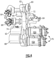
- FIG. 1 schematically illustrates a gas turbine engine 20.
- the gas turbine engine 20 is disclosed herein as a two-spool turbofan that generally incorporates a fan section 22, a compressor section 24, a combustor section 26 and a turbine section 28.
- Alternative engines might include an augmentor section (not shown) among other systems or features.
- the fan section 22 drives air along a bypass flow path B in a bypass duct defined within a nacelle 15, while the compressor section 24 drives air along a core flow path C for compression and communication into the combustor section 26 then expansion through the turbine section 28.
- the exemplary engine 20 generally includes a low speed spool 30 and a high speed spool 32 mounted for rotation about an engine central longitudinal axis A relative to an engine static structure 36 via several bearing systems 38. It should be understood that various bearing systems 38 at various locations may alternatively or additionally be provided, and the location of bearing systems 38 may be varied as appropriate to the application.
- the low speed spool 30 generally includes an inner shaft 40 that interconnects a fan 42, a first (or low) pressure compressor 44 and a first (or low) pressure turbine 46.
- the inner shaft 40 is connected to the fan 42 through a speed change mechanism, which in exemplary gas turbine engine 20 is illustrated as a geared architecture 48 to drive the fan 42 at a lower speed than the low speed spool 30.
- the high speed spool 32 includes an outer shaft 50 that interconnects a second (or high) pressure compressor 52 and a second (or high) pressure turbine 54.
- a combustor 56 is arranged in exemplary gas turbine engine 20 between the high pressure compressor 52 and the high pressure turbine 54.
- a mid-turbine frame 58 of the engine static structure 36 is arranged generally between the high pressure turbine 54 and the low pressure turbine 46.
- the mid-turbine frame 58 further supports bearing systems 38 in the turbine section 28.
- the inner shaft 40 and the outer shaft 50 are concentric and rotate via bearing systems 38 about the engine central longitudinal axis A which is collinear with their longitudinal axes.
- the core airflow is compressed by the low pressure compressor 44 then the high pressure compressor 52, mixed and burned with fuel in the combustor 56, then expanded over the high pressure turbine 54 and low pressure turbine 46.
- the mid-turbine frame 58 includes airfoils 60 which are in the core airflow path C.
- the turbines 46, 54 rotationally drive the respective low speed spool 30 and high speed spool 32 in response to the expansion.
- each of the positions of the fan section 22, compressor section 24, combustor section 26, turbine section 28, and geared architecture 48 may be varied.
- geared architecture 48 may be located aft of combustor section 26 or even aft of turbine section 28, and fan section 22 may be positioned forward or aft of the location of gear architecture 48.
- the engine 20 in one example is a high-bypass geared aircraft engine.
- the engine 20 bypass ratio is greater than about six, with an example embodiment being greater than about ten
- the geared architecture 48 is an epicyclic gear train, such as a planetary gear system or other gear system, with a gear reduction ratio of greater than about 2.3 and the low pressure turbine 46 has a pressure ratio that is greater than about five.
- the engine 20 bypass ratio is greater than about ten
- the fan diameter is significantly larger than that of the low pressure compressor 44
- the low pressure turbine 46 has a pressure ratio that is greater than about five.
- Low pressure turbine 46 pressure ratio is pressure measured prior to inlet of low pressure turbine 46 as related to the pressure at the outlet of the low pressure turbine 46 prior to an exhaust nozzle.
- the geared architecture 48 may be an epicycle gear train, such as a planetary gear system or other gear system, with a gear reduction ratio of greater than about 2.3:1. It should be understood, however, that the above parameters are only exemplary of one embodiment of a geared architecture engine and that the present invention is applicable to other gas turbine engines including direct drive turbofans.
- the fan section 22 of the engine 20 is designed for a particular flight condition - typically cruise at about 0.8 Mach and about 35,000 feet (10.67 km).
- the flight condition of 0.8 Mach and 35,000 ft (10.67 km), with the engine at its best fuel consumption -also known as “bucket cruise Thrust Specific Fuel Consumption ('TSFC')" - is the industry standard parameter of lbm of fuel being burned divided by lbf of thrust the engine produces at that minimum point.
- “Low fan pressure ratio” is the pressure ratio across the fan blade alone, without a Fan Exit Guide Vane (“FEGV”) system.
- the low fan pressure ratio as disclosed herein according to one non-limiting embodiment is less than about 1.45.
- the "Low corrected fan tip speed” as disclosed herein according to one non-limiting embodiment is less than about 1150 ft/second (350 m/second).
- the example gas turbine engine includes the fan 42 that comprises in one non-limiting embodiment less than about twenty-six fan blades. In another non-limiting embodiment, the fan section 22 includes less than about twenty fan blades. Moreover, in one disclosed embodiment the low pressure turbine 46 includes no more than about six turbine rotors schematically indicated at 34. In another non-limiting example embodiment the low pressure turbine 46 includes about three turbine rotors. A ratio between the number of fan blades and the number of low pressure turbine rotors is between about 3.3 and about 8.6. The example low pressure turbine 46 provides the driving power to rotate the fan section 22 and therefore the relationship between the number of turbine rotors 34 in the low pressure turbine 46 and the number of blades in the fan section 22 disclose an example gas turbine engine 20 with increased power transfer efficiency.
- the example engine 20 includes a first towershaft 64 that is engaged to drive the high speed spool 32.
- the engine 20 further includes a second towershaft 66 that is engaged to be driven by the low speed spool 30.
- the low speed spool 30 includes a gear 70 and the high speed spool 32 includes a gear 68.
- the gear 68 is engaged to the first towershaft 64 and the gear 70 is engaged to the second towershaft 66.
- the gears 68 and 70 are bevel gears and engage corresponding bevel gears on the corresponding first or second towershaft 64, 66.
- the example gearbox 62 includes a gear engagement with both the first towershaft 64 and the second towershaft 66.
- the towershafts 64, 66 interface with a common accessory gearbox 62 and enable the use of the low speed spool 30 to drive the accessory components within the accessory gearbox 62.
- a first clutch 72 is engaged to the first towershaft 64 coupled to the high speed spool 32.
- a second clutch 74 is disposed on the second towershaft 66 driven by the low speed spool 30.
- Each of the clutches 74 and 72 provide for the transmission of torque in a single direction.
- the accessory gearbox 62 is engaged to a starter generator assembly 76 that drives a set of gears 78 meshing with both the first towershaft 64 and the second towershaft 66.
- the clutches 72 and 74 are sprag clutches that only allow torque to be transmitted in one direction. When torque is reversed, meaning that the driving member becomes the driven member, the clutch will slip and allow the driving member to overspeed relative to the driven member.
- the second clutch 74 will allow the low rotor to drive the starter generator assembly 76, but does not allow the starter generator assembly 76 to drive low speed spool 30.
- the first clutch 72 can be located within the accessory gearbox 62, however, the first clutch 74 may be located wherever practical to provide the selective application of torque between the starter generator assembly 76 and the first towershaft 64. Similarly, the second clutch 74 can be located wherever practical to provide selective application of torque.
- the first clutch 72 is configured to allow the starter generator assembly 76 to drive the high speed spool 32 but not to allow the high speed spool 32 to drive the starter generator assembly 76. In this example, because the high speed spool 32 will rotate much faster than the starter generator assembly 76, the first clutch 72 is configured such that the high speed spool 32 may over speed past the speed of the starter generator assembly 76 and not transmit torque to the starter generator assembly 76 through the first towershaft 64.
- the accessory gearbox 62 is used to drive the starter generator assembly 76, and a number of other accessory components, including, but not limited to a compressor 80, an oil pump 84, a hydraulic pump 88, and a permanent magnet alternator (PMA) 90.
- the first clutch 72 is positioned such that the first towershaft 64 can selectively drive the compressor 80 and the permanent magnet alternator 90.
- the second clutch 74 is positioned such that the second towershaft 66 can selectively drive the oil pump 84, and further drive the hydraulic pump 88 and the starter generator assembly 76 through a transmission 92.
- a fuel pump (not shown) can be electrically driven and powered by the starter generator assembly 76.
- the first clutch 72 effectively decouples rotation of the first towershaft 64, the compressor 80, and the permanent magnet alternator 90 from the rotations of the second towershaft 66, the transmission 92, the starter generator assembly 76, the hydraulic pump 88, and the oil pump 84. This permits the first towershaft 64 to drive the compressor 80 and the permanent magnet alternator 90 while the second towershaft 66 drives the remaining accessories.
- the compressor 80 in this example, is a boost compressor pump used within an intercooled cooling air (I-CCA) system 100 as shown in Figure 5 .
- the system 100 generally, permits cooling the high turbine with secondary air.
- the fan 42 delivers air into a bypass duct 106 as propulsion air.
- the fan 42 also delivers air to the low pressure compressor 44.
- the air then passes into the high pressure compressor 52.
- a tap 112 is shown in the high pressure compressor 52 adjacent a downstream most end 113 of the compressor 52.
- Another tap 114 is shown at a location upstream of the downstream most end 113. Air compressed by the compressor 52 passes into the combustor 56.
- the air is mixed with fuel and ignited and products of this combustion pass over the high pressure turbine 54.
- a second turbine there will typically be at least a second turbine.
- the geared architecture 48 is shown between a shaft 121 driven by a fan drive turbine (which may be the second turbine or the third turbine, if one is included).
- Air from the tap 114 is utilized as cooling air. It passes through a valve 120 to a heat exchanger 122.
- the air in the heat exchanger 122 is cooled by the bypass air in duct 106. Of course, other locations for the heat exchanger may be selected. Downstream of the heat exchanger 122 air passes through the compressor 80.
- the boost compressor 80 is driven by the first towershaft 64 through the set of gears 78 in the accessory gearbox 62.
- Air downstream of the boost compressor 80 passes through a heat exchanger 128, and then to a mixing chamber 130. It should be understood that while two heat exchangers 122 and 128 are illustrated, only one heat exchanger may be needed.
- air from the downstream location 112 is mixed with the air from the location 114 to arrive at a desired mix of temperature and pressure to be delivered at line 132 to cool the high pressure turbine 54.
- the mixing chamber 130 may be a passive orifice feature. As long as the pressure downstream of the boost compressor 80 is higher than the air from location 112, the air from the boost compressor 80 will flow for cooling. Air from the tap 112 can make up any difference in the required flow volume.
- a control 134 controls the mixing chamber 130. It should be understood that the other valves and other items could also be controlled by the control 134. Control 134 may be a standalone control or may be part of a full authority digital electronic controller (FADEC).
- FADEC full authority digital electronic controller
- the second towershaft 66 drives the hydraulic pump 88 and the starter generator assembly 76 through a transmission 92.
- the oil pump 84 is driven by the second towershaft 66, but not through the transmission 92.
- the rotational speed of the oil pump 84 varies linearly with the rotational speed of the second towershaft 66.
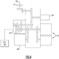
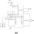
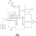
- the transmission 92 is a three-speed transmission that can transition between a first mode of shown schematically in Figure 6 , a second mode shown schematically in Figure 7 , and a third mode shown schematically in Figure 8 .
- the transmission 92 is rotated by the second towershaft 66 and, in response, rotates the hydraulic pump 88 and the starter generator assembly 76 at a first ratio relative to a rotational speed of the second towershaft 66.
- the transmission 92 is rotated by the second towershaft 66 and, in response, rotates the hydraulic pump 88 and the starter generator assembly 76 at a different, second ratio relative to a rotational speed of the second towershaft 66.
- the transmission 92 is rotated by the second towershaft 66 and, in response, rotates the hydraulic pump 88 and the starter generator assembly 76 at a different, third ratio relative to a rotational speed of the second towershaft 66.
- the inner shaft 40 can experience a greater range of rotational speeds that the outer shaft 50. That is, the speed excursion for the inner shaft 40 can be higher than the speed excursion for the outer shaft 50.
- the inner shaft 40 can operate at speed excursions of up to 80% during operation of the gas turbine engine 20, whereas the outer shaft 50 can operate at speed excursions of up to 30% during operation of the gas turbine engine 20.
- the transmission 92 addresses issues associated with rotating the starter generator assembly 76 and the hydraulic pump 88 with a rotatable input from the second towershaft 66.
- the transmission 92 operates in the first mode when the inner shaft 40 is rotating at a speed excursion of say less than 25%. If the speed excursion of the inner shaft 40 meets or exceeds 25%, but is less than 50%, the transmission 92 switches to the second mode to rotate the starter generator assembly 76 and the hydraulic pump 88. If the speed excursion of the inner shaft 40 meets or exceeds 50%, the transmission 92 switches to the third mode to rotate the starter generator assembly 76 and the hydraulic pump 88.
- the starter generator assembly 76 is thus not required to operate across a range of speed excursions from 0 up to 80% during operation of the gas turbine engine 20. Instead, due to the transmission 92, the range is no more than, say, 30% for the starter generator assembly 76 and the hydraulic pump 88.
- the starter generator assembly 76 can operate more efficiently when the starter generator assembly 76 and the hydraulic pump 88 is rotated across a smaller range of rotational speeds than across a larger range of rotational speeds.
- An electronic engine control (EEC) 96 can control the transition of the transmission 92 between the first mode, the second mode, and the third mode.
- the EEC 96 could, for example, receive an input corresponding to the rotational speed of the inner shaft 40, and then transition the transmission 92 from the first mode to the second mode or the third mode when the rotational speed exceeds a threshold speed.
- the exemplary transmission 92 can transition between three modes, other exemplary embodiments of the transmission 92 could transition between more than three modes.
- the transmission 92 is rotated by the second towershaft 66 through the first set of gears 78 and, in response, rotates the starter generator assembly 76 and the hydraulic pump 88 at four or more different ratios relative to a rotational speed of the second towershaft 66.
- the example accessory gearbox 62 is shown during an engine starting operation.
- the starter generator assembly 76 is shown driving the set of gears 78 within the accessory gearbox 62 that, in turn, drives the first clutch 72 and thereby the first towershaft 64 to drive the high speed spool 32 up to a speed required for starting of the engine 20.
- the same set of gears 78 driven by the starter generator assembly 76 is also driving the second clutch 74 that is engaged to the second towershaft 66 driven by the low speed spool 30.
- the second clutch 74 is not transmitting torque to the low speed spool 30. Accordingly, in the configuration schematically illustrated in Figure 9 , only the high speed spool 32 is turning.
- the high speed spool 32 Once the high speed spool 32 has been spun up to operating conditions, it will attain a speed that is much greater than that input by the starter generator assembly 76 and the first towershaft 64.
- the first towershaft 64 will continue to rotate in a direction originally provided by the starter generator assembly 76, however, the high speed spool driven towershaft 64 is rotating at a much higher speed and therefore spin past the speed input by the starter generator assembly 76.
- the first clutch 72 will not allow the transmission of this higher torque from the high speed spool 32 to accessory components other than the permanent magnet alternator 90 and the compressor 80.
- the low speed spool 30 will also begin to turn and shown in Figure 10 .
- Rotation of the high speed spool will result in turning of the second towershaft 66.
- the second towershaft 66 will in turn, turn the set of gears 78 through the second clutch 74 which will drive the starter generator assembly 76.
- the second clutch 74 is orientated and configured to enable the low speed spool 30 to drive the towershaft 66 and in turn drive the starter generator assembly 76.
- the starter generator assembly 76 may produce electric power to drive any number of accessory units.
- the accessory components can be electrically powered by the starter generator assembly 76 or mechanically powered by the low speed spool 30.
- the starter generator assembly 76 comprises two separate variable frequency generators.
- the variable frequency generators are each rated at 90 kVA in some examples.
- both starters can be powered to shorten start time.
- one of the starter-generators can be engaged to turn the high speed spool and reduced a bowed rotor start.
- variable frequency generators receives a rotational input to generate power utilized by components of the gas turbine engine 20.
- Other examples could incorporate other types of generators, and other types of electric machines.
- the transmission 92 facilitates incorporating the variable frequency generators rather than, for example, an integrated drive generator, since the transmission 92 permits operating the starter generator assembly 76 to operate in a narrower rpm range while still being driven by rotation of the inner shaft 40 through the second towershaft 66.
- Other examples, however, could include using one or more integrated drive generators as the starter generator assembly 76.
- the hydraulic pump 88 ( Figure 4 ) generally moves hydraulic fluid needed to move components of an air frame to which the gas turbine engine 20 is mounted.
- the transmission 92 permits operating the hydraulic pump 88 to be driven in a narrower rpm range while still being driven by rotation of the inner shaft 40 through the second towershaft 66.
- Driving the hydraulic pump 88 with the inner shaft 40, rather than the outer shaft 50, can improve engine operability and performance.
- the exhaust gas temperature is also reduced as there is less power draw on the outer shaft 50.
- the oil pump 84 is driven at a fixed ratio relative to the speed of the second towershaft 66. That is, switching the transmission 92 between the various modes does not substantially change a ratio of rotational speeds between the second towershaft 66 and the oil pump 84. Thus, as the rotational speed of the second towershaft 66 varies, the rotational input to the oil pump 84 varies linearly with the rotational speed of the second towershaft 66.
- the oil pump 84 can be dedicated to supplying oil for all low rotor bearings whether roller, ball, or tapered bearings, and further including supplying oil for the geared architecture 48 or fan drive gear system.
- the oil pump 84 is dedicated to supplying oil to the low rotor bearing system 38', which incorporates bearings directly supporting the inner shaft 40.
- the bearings of the low rotor bearing system 38' are tapered bearings in some examples.
- the rotational speed of the second towershaft 66 increases when the rotational speed of the inner shaft 40 increases.
- the inner shaft 40 may require additional lubrication, such as oil, directed to bearing systems 38 supporting the inner shaft 40 when the rotational speed of the inner shaft 40 increases.
- the increased lubrication demands due to increasing the rotational speed of the inner shaft 40 are met by increasing the rotational input speed to the oil pump 84.
- the amount of oil moved to the bearing system 38' varies linearly with the rotational speed of the inner shaft 40. If the oil pump 84 were instead varying linearly with the rotational speed of the outer shaft 50, the oil pump 84 may move more oil than is required for lubrication. The excess oil would need to recirculated, or accommodated in some other way, which results in losses.
- the oil pump 84 is considered a 60% oil pump as it accommodates approximately 60% of the lubrication requirements for the gas turbine engine 20.
- the permanent magnet alternator 90 can be used to power the FADEC, which can include the EEC 96. As the FADEC is used during start up, the permanent magnet alternator 90 is also driven by the outer shaft 50.
- an added feature of coupling rotation of the oil pump 84 with rotation of the inner shaft 40 is that the inner shaft 40 spins with the fan 42.
- the oil pump 84 can continue to pump oil lubricating the bearings associated with the inner shaft 40. If the oil pump 84 were decoupled from rotation with the inner shaft 40, another pump or an electronic pump could be required to move oil to lubricate the fan 42 when windmilling.
- some of the exemplary accessory gearboxes and related components enable the use of compact high speed spool systems to enhance efficiencies.
- Some of the disclosed exemplary embodiments can be used to replace fuel and oil pumps with electrically powered on-demand fuel and oil pumps.
- the fuel pump formerly driven by the accessory gearbox is replaced with a compressor that is part of an intercooled cooling air system.
- Some of the exemplary embodiments can improve fuel burn over arrangements with a starter generator assembly driven in a generator mode by the high spool. Since the starter generators drive the high spool when the engine is started, and then transitioned away from the high spool, no additional starter on the high spool is required. Using the starter-generators can reduce idle thrust and ground/flight idle exhaust gas temperatures. The starter-generators can facilitate wing anti-ice.
Landscapes
- Engineering & Computer Science (AREA)
- Chemical & Material Sciences (AREA)
- Combustion & Propulsion (AREA)
- General Engineering & Computer Science (AREA)
- Mechanical Engineering (AREA)
- Power Engineering (AREA)
- Connection Of Motors, Electrical Generators, Mechanical Devices, And The Like (AREA)
- Control Of Turbines (AREA)
- Structures Of Non-Positive Displacement Pumps (AREA)
Claims (13)
- Gasturbinenmotorbaugruppe (20), Folgendes umfassend:eine erste Spule (32) mit einer ersten Turbine (54), die betriebsmäßig an einer ersten Turbinenwelle (50) montiert ist;eine zweite Spule (30) mit einer zweiten Turbine (46), die betriebsmäßig an einer zweiten Turbinenwelle (40) montiert ist, wobei die erste und die zweite Turbine (54, 46) zur Drehung um eine gemeinsame Drehachse (A) innerhalb einer statischen Motorstruktur montiert sind und die erste und die zweite Turbinenwelle (50, 40) koaxial zueinander sind;eine erste und eine zweite Turmwelle (64, 66), die jeweils mit der ersten und der zweiten Turbinenwelle (50, 40) gekoppelt sind;ein Hilfsantriebsgetriebe (62) mit einem ersten Satz von Zahnrädern;einen Kompressor (80), der durch die erste Turmwelle (64) angetrieben wird, wobei der Kompressor (80) ein Zusatzkompressor eines zwischengekühlten Kühlluftsystems (100) ist;eine Startergeneratorbaugruppe (76); undeine Übertragungseinrichtung (92), die die Startergeneratorbaugruppe (76) mit dem ersten Satz von Zahnrädern koppelt, wobei die Übertragungseinrichtung (92) zwischen einem ersten Modus, in dem die Startergeneratorbaugruppe (76) mit einer ersten Drehzahl relativ zu der zweiten Turmwelle (66) angetrieben wird, und einem zweiten Modus, in dem die Startergeneratorbaugruppe (76) mit einer anderen, zweiten Drehzahl relativ zu der zweiten Turmwelle (66) angetrieben wird, umschaltbar ist,dadurch gekennzeichnet, dass:
die Gasturbinenmotorbaugruppe (20) ferner eine erste Kupplung (72), die zwischen der ersten Turmwelle (64) und der Startergeneratorbaugruppe (76) angeordnet ist, wobei die erste Kupplung (72) dazu konfiguriert ist, es der Startergeneratorbaugruppe (76) zu ermöglichen, die erste Spule (32) durch das Hilfsantriebsgetriebe (62) anzutreiben, und eine zweite Kupplung (74), die zwischen der zweiten Turmwelle (66) und der Startergeneratorbaugruppe (76) angeordnet ist, wobei die zweite Kupplung (74) dazu konfiguriert ist, es der zweiten Spule (30) zu ermöglichen, die Startergeneratorbaugruppe (76) durch das Hilfsantriebsgetriebe (62) anzutreiben, umfasst. - Gasturbinenmotorbaugruppe (20) nach Anspruch 1, wobei die erste und die zweite Turbinenwelle (50, 40) jeweils eine Außen-und eine Innenwelle sind und die erste und die zweite Turbine (54, 46) jeweils eine Hoch- und eine Niederdruckturbine sind, optional wobei die erste Turmwelle (64) dazu konfiguriert ist, sich mit einer höheren Geschwindigkeit als die zweite Turmwelle (66) zu drehen.
- Gasturbinenmotorbaugruppe (20) nach Anspruch 1 oder 2, wobei die Übertragungseinrichtung (92) ferner in einen dritten Modus umschaltbar ist, in dem die Startergeneratorbaugruppe (76) mit einer anderen, dritten Drehzahl relativ zu der zweiten Turmwelle (66) angetrieben wird, optional wobei die Übertragungseinrichtung (92) ferner in mindestens einen vierten Modus umschaltbar ist, in dem die Startergeneratorbaugruppe (76) mit einer vierten Drehzahl relativ zu der zweiten Turmwelle (66) angetrieben wird, wobei sich die vierte Drehzahl von jeder von der ersten, zweiten und dritten Drehzahl unterscheidet.
- Gasturbinenmotor (20) nach einem der vorhergehenden Ansprüche, wobei die erste Kupplung (72) und die zweite Kupplung (74) mechanische Einwegkupplungsvorrichtungen sind.
- Gasturbinenmotorbaugruppe (20) nach einem der vorhergehenden Ansprüche, ferner einen Kompressorabschnitt (52) mit einem am weitesten stromabwärts gelegenen Ende (113) und einem Kühllufthahn (114) an einer Stelle, die stromaufwärts von dem am weitesten stromabwärts gelegenen Ende (113) beabstandet ist, umfassend, wobei der Kühllufthahn (114) durch den Zusatzkompressor (80) und mindestens einen Wärmetauscher (122, 128) und dann zu einem Turbinenabschnitt (28) geleitet wird, um den Turbinenabschnitt (28) zu kühlen.
- Gasturbinenmotorbaugruppe (20) nach einem der vorhergehenden Ansprüche, ferner ein durch eine Drehzahlreduziervorrichtung (48) angetriebenes Gebläse (22) umfassend, wobei die Drehzahlreduziervorrichtung (48) durch die zweite Turbinenwelle (40) angetrieben wird.
- Gasturbinenmotorbaugruppe (20) nach einem der vorhergehenden Ansprüche, wobei die Startergeneratorbaugruppe (76) einen ersten Generator mit variabler Frequenz und einen zweiten Generator mit variabler Frequenz umfasst.
- Gasturbinenmotorbaugruppe (20) nach einem der Ansprüche 1 bis 6, wobei die Startergeneratorbaugruppe (76) einen ersten integrierten Antriebsgenerator und einen zweiten integrierten Antriebsgenerator umfasst.
- Verfahren zum Betreiben eines Gasturbinenmotors (20), Folgendes umfassend:Antreiben einer ersten Spule (32) mit einem Starter durch eine erste Turmwelle (64) und eine erste Kupplung (72), um den Motor (20) zu starten;Antreiben einer Startergeneratorbaugruppe (76) über ein Hilfsgetriebe (62) durch eine zweite Kupplung (74) mit einer zweiten Turmwelle (66), die mit einer zweiten Spule (30) gekoppelt wird, sobald der Motor (20) gestartet ist; undAntreiben eines Kompressors (80) durch das Hilfsgetriebe (62) mit der ersten Turmwelle, sobald der Motor (20) gestartet ist, wobei der Kompressor (80) ein Zusatzkompressor eines zwischengekühlten Kühlluftsystems (100) ist,dadurch gekennzeichnet, dass:
das Verfahren ferner das Antreiben des Startergenerators (76) durch eine Übertragungseinrichtung (92) in einem ersten Modus, sodass die Startergeneratorbaugruppe (76) mit einer ersten Geschwindigkeit relativ zu der zweiten Turmwelle (66) gedreht wird, und das Umschalten der Übertragungseinrichtung (92) in einen zweiten Modus, sodass der Startergenerator (76) durch die zweite Turmwelle (66) angetrieben wird und mit einer anderen, zweiten Geschwindigkeit relativ zu der zweiten Turmwelle (66) gedreht wird, umfasst. - Verfahren nach Anspruch 10, ferner das Entkoppeln des Starters von der ersten Spule (32) umfassend, sobald die erste Spule (32) eine Motorleerlaufdrehzahl erreicht, optional wobei das Entkoppeln das Drehen der zweiten Turmwelle mit einer höheren Drehzahl als der des Starters beinhaltet.
- Verfahren nach Anspruch 9 oder 10, ferner einen Kompressorabschnitt (52) mit einem am weitesten stromabwärts gelegenen Ende (113) und einem Kühllufthahn (114) an einer Stelle, die stromaufwärts von dem am weitesten stromabwärts gelegenen Ende (113) beabstandet ist, umfassend, wobei der Kühllufthahn (114) durch den Zusatzkompressor (80) und mindestens einen Wärmetauscher (122, 128) geleitet wird und dann zu einem Turbinenabschnitt (28) geleitet wird, um den Turbinenabschnitt (28) zu kühlen.
- Verfahren nach einem der Ansprüche 9 bis 11, ferner das Umschalten der Übertragungseinrichtung (92) in einen dritten Modus; und das Antreiben der Übertragungseinrichtung (92) mit der zweiten Turmwelle (66), um die Startergeneratorbaugruppe (76) mit einer anderen, dritten Drehzahl relativ zu der zweiten Turmwelle (66) zu drehen, umfassend.
- Verfahren nach einem der Ansprüche 9 bis 12, ferner das Antreiben eines Gebläses (22) durch eine Drehzahlreduziervorrichtung (48) mit einer Welle (40) der zweiten Spule (30) umfassend.
Applications Claiming Priority (1)
| Application Number | Priority Date | Filing Date | Title |
|---|---|---|---|
| US15/410,113 US10995673B2 (en) | 2017-01-19 | 2017-01-19 | Gas turbine engine with intercooled cooling air and dual towershaft accessory gearbox |
Publications (3)
| Publication Number | Publication Date |
|---|---|
| EP3351769A1 EP3351769A1 (de) | 2018-07-25 |
| EP3351769B1 EP3351769B1 (de) | 2021-05-19 |
| EP3351769B2 true EP3351769B2 (de) | 2024-11-20 |
Family
ID=61017833
Family Applications (1)
| Application Number | Title | Priority Date | Filing Date |
|---|---|---|---|
| EP18152645.0A Active EP3351769B2 (de) | 2017-01-19 | 2018-01-19 | Gasturbinenmotor mit zwei achsabtiebswellen sowie betriebsverfahren |
Country Status (2)
| Country | Link |
|---|---|
| US (2) | US10995673B2 (de) |
| EP (1) | EP3351769B2 (de) |
Families Citing this family (33)
| Publication number | Priority date | Publication date | Assignee | Title |
|---|---|---|---|---|
| JP6343243B2 (ja) * | 2015-03-09 | 2018-06-13 | 川崎重工業株式会社 | 航空機用発電装置 |
| US11415063B2 (en) | 2016-09-15 | 2022-08-16 | Pratt & Whitney Canada Corp. | Reverse-flow gas turbine engine |
| US10883424B2 (en) | 2016-07-19 | 2021-01-05 | Pratt & Whitney Canada Corp. | Multi-spool gas turbine engine architecture |
| US11035293B2 (en) | 2016-09-15 | 2021-06-15 | Pratt & Whitney Canada Corp. | Reverse flow gas turbine engine with offset RGB |
| US10465611B2 (en) | 2016-09-15 | 2019-11-05 | Pratt & Whitney Canada Corp. | Reverse flow multi-spool gas turbine engine with aft-end accessory gearbox drivingly connected to both high pressure spool and low pressure spool |
| US10815899B2 (en) | 2016-11-15 | 2020-10-27 | Pratt & Whitney Canada Corp. | Gas turbine engine accessories arrangement |
| US10422243B2 (en) * | 2017-01-19 | 2019-09-24 | United Technologies Corporation | Gas turbine engine dual towershaft accessory gearbox and starter generator assembly |
| US10808624B2 (en) | 2017-02-09 | 2020-10-20 | Pratt & Whitney Canada Corp. | Turbine rotor with low over-speed requirements |
| US10746188B2 (en) | 2017-03-14 | 2020-08-18 | Pratt & Whitney Canada Corp. | Inter-shaft bearing connected to a compressor boost system |
| US10358981B2 (en) | 2017-04-11 | 2019-07-23 | United Technologies Corporation | High and low spool accessory gearbox drive |
| FR3066444B1 (fr) * | 2017-05-19 | 2021-04-16 | Safran | Architecture propulsive hybride d'aeronef comprenant un moteur avec une machine electrique reversible montee sur deux arbres |
| US10787930B2 (en) * | 2018-03-23 | 2020-09-29 | Raytheon Technologies Corporation | Windmill lubrication gear train for lubricant system in a geared gas turbine engine |
| US12259036B2 (en) | 2018-04-20 | 2025-03-25 | Rtx Corporation | Electric motor driven auxiliary oil system for geared gas turbine engine |
| EP3653859B1 (de) | 2018-08-08 | 2024-02-07 | Pratt & Whitney Canada Corp. | Mehrmotoriges system und verfahren |
| US10920671B2 (en) | 2018-09-25 | 2021-02-16 | Raytheon Technologies Corporation | Thrust balance control with differential power extraction |
| US10634064B1 (en) * | 2018-10-11 | 2020-04-28 | United Technologies Corporation | Accessory gearbox with superposition gearbox |
| FR3092617B1 (fr) * | 2019-02-12 | 2022-07-08 | Safran Aircraft Engines | Ensemble comprenant un boitier d’accessoires pour une turbomachine |
| US11346427B2 (en) * | 2019-02-13 | 2022-05-31 | Raytheon Technologies Corporation | Accessory gearbox for gas turbine engine with variable transmission |
| US11608784B2 (en) | 2019-02-13 | 2023-03-21 | Raytheon Technologies Corporation | Accessory gearbox for gas turbine engine with compressor drive |
| US11226026B2 (en) | 2019-04-18 | 2022-01-18 | Hamilton Sundstrand Corporation | Multispeed transmission |
| US11041462B2 (en) | 2019-06-05 | 2021-06-22 | Raytheon Technologies Corporation | Hybrid turbofan with differential electrical and mechanical power transfer |
| CA3177001A1 (en) * | 2020-05-04 | 2021-11-11 | Marco Santini | Gas turbines in mechanical drive applications and operating methods thereof |
| CN111577451A (zh) * | 2020-05-22 | 2020-08-25 | 中国航发沈阳发动机研究所 | 一种发动机功率提取结构及其操纵方法 |
| US11891899B1 (en) * | 2020-07-10 | 2024-02-06 | Rtx Corporation | Dual engine system |
| JP7535123B2 (ja) * | 2020-10-28 | 2024-08-15 | 川崎重工業株式会社 | 圧縮空気供給システム |
| US12037913B2 (en) * | 2020-11-02 | 2024-07-16 | Ge Avio S.R.L. | Electric machine assembly for a turbine engine |
| CN113339080B (zh) * | 2021-06-08 | 2022-07-05 | 内蒙古京泰发电有限责任公司 | 一种汽轮发电机组大功率水泵/风机驱动耦合装置 |
| FR3124545B1 (fr) * | 2021-06-28 | 2023-06-23 | Safran Aircraft Engines | Ensemble pour turbomachine d’aéronef comprenant un support d’équipements |
| US11976598B2 (en) | 2022-05-05 | 2024-05-07 | Rtx Corporation | Transmission and method for control of boost spool |
| US11639690B1 (en) | 2022-05-05 | 2023-05-02 | Raytheon Technologies Corporation | Boost spool flow control and generator load matching via load compressor |
| US11692493B1 (en) | 2022-05-05 | 2023-07-04 | Raytheon Technologies Corporation | Fluidic valve configuration for boost spool engine |
| US11898490B2 (en) | 2022-05-05 | 2024-02-13 | Rtx Corporation | Transmission and method for control of boost spool |
| US11692491B1 (en) | 2022-05-05 | 2023-07-04 | Raytheon Technologies Corporation | Transmission and method for control of boost spool |
Family Cites Families (163)
| Publication number | Priority date | Publication date | Assignee | Title |
|---|---|---|---|---|
| US2692476A (en) | 1950-11-13 | 1954-10-26 | Boeing Co | Gas turbine engine air starting motor constituting air supply mechanism |
| GB1244340A (en) | 1968-12-23 | 1971-08-25 | Rolls Royce | Front fan gas turbine engine |
| US3878677A (en) | 1974-04-10 | 1975-04-22 | United Aircraft Corp | Auxiliary turbine/compressor system for turbine engine |
| US4254618A (en) | 1977-08-18 | 1981-03-10 | General Electric Company | Cooling air cooler for a gas turbofan engine |
| JPS5477820A (en) | 1977-12-02 | 1979-06-21 | Hitachi Ltd | Method of cooling gas turbine blade |
| IT8322002U1 (it) | 1983-05-31 | 1984-12-01 | Same Spa | Gruppo motore a combustione interna con impianto di ventilazione di pompe iniezione |
| US4561246A (en) | 1983-12-23 | 1985-12-31 | United Technologies Corporation | Bearing compartment for a gas turbine engine |
| US4882902A (en) | 1986-04-30 | 1989-11-28 | General Electric Company | Turbine cooling air transferring apparatus |
| DE59102139D1 (de) | 1990-03-23 | 1994-08-18 | Asea Brown Boveri | Axialdurchströmte Gasturbine. |
| US5056335A (en) | 1990-04-02 | 1991-10-15 | General Electric Company | Auxiliary refrigerated air system employing input air from turbine engine compressor after bypassing and conditioning within auxiliary system |
| US5123242A (en) | 1990-07-30 | 1992-06-23 | General Electric Company | Precooling heat exchange arrangement integral with mounting structure fairing of gas turbine engine |
| US5269135A (en) | 1991-10-28 | 1993-12-14 | General Electric Company | Gas turbine engine fan cooled heat exchanger |
| US5305616A (en) | 1992-03-23 | 1994-04-26 | General Electric Company | Gas turbine engine cooling system |
| US5392614A (en) | 1992-03-23 | 1995-02-28 | General Electric Company | Gas turbine engine cooling system |
| US5414992A (en) | 1993-08-06 | 1995-05-16 | United Technologies Corporation | Aircraft cooling method |
| US5452573A (en) | 1994-01-31 | 1995-09-26 | United Technologies Corporation | High pressure air source for aircraft and engine requirements |
| US5498126A (en) | 1994-04-28 | 1996-03-12 | United Technologies Corporation | Airfoil with dual source cooling |
| DE19531562A1 (de) | 1995-08-28 | 1997-03-06 | Abb Management Ag | Verfahren zum Betrieb einer Kraftwerksanlage |
| US5724806A (en) | 1995-09-11 | 1998-03-10 | General Electric Company | Extracted, cooled, compressed/intercooled, cooling/combustion air for a gas turbine engine |
| GB9606546D0 (en) | 1996-03-28 | 1996-06-05 | Rolls Royce Plc | Gas turbine engine system |
| US5918458A (en) | 1997-02-14 | 1999-07-06 | General Electric Company | System and method of providing clean filtered cooling air to a hot portion of a gas turbine engine |
| JP2941748B2 (ja) | 1997-07-15 | 1999-08-30 | 三菱重工業株式会社 | ガスタービン冷却装置 |
| JPH1193694A (ja) | 1997-09-18 | 1999-04-06 | Toshiba Corp | ガスタービンプラント |
| US6430931B1 (en) | 1997-10-22 | 2002-08-13 | General Electric Company | Gas turbine in-line intercooler |
| US6065282A (en) | 1997-10-29 | 2000-05-23 | Mitsubishi Heavy Industries, Ltd. | System for cooling blades in a gas turbine |
| US6050079A (en) * | 1997-12-24 | 2000-04-18 | General Electric Company | Modulated turbine cooling system |
| US6134880A (en) | 1997-12-31 | 2000-10-24 | Concepts Eti, Inc. | Turbine engine with intercooler in bypass air passage |
| AU1177100A (en) | 1999-11-10 | 2001-06-06 | Hitachi Limited | Gas turbine equipment and gas turbine cooling method |
| DE10001112A1 (de) | 2000-01-13 | 2001-07-19 | Alstom Power Schweiz Ag Baden | Kühlluftkühler für eine Gasturbinenanlage sowie Verwendung eines solchen Kühlluftkühlers |
| DE10009655C1 (de) | 2000-02-29 | 2001-05-23 | Mtu Aero Engines Gmbh | Kühlluftsystem |
| US6487863B1 (en) | 2001-03-30 | 2002-12-03 | Siemens Westinghouse Power Corporation | Method and apparatus for cooling high temperature components in a gas turbine |
| DE10122695A1 (de) | 2001-05-10 | 2002-11-21 | Siemens Ag | Verfahren zur Kühlung einer Gasturbine und Gasturbinenanlage |
| JP3849473B2 (ja) | 2001-08-29 | 2006-11-22 | 株式会社日立製作所 | ガスタービンの高温部冷却方法 |
| US6550253B2 (en) | 2001-09-12 | 2003-04-22 | General Electric Company | Apparatus and methods for controlling flow in turbomachinery |
| US6651929B2 (en) | 2001-10-29 | 2003-11-25 | Pratt & Whitney Canada Corp. | Passive cooling system for auxiliary power unit installation |
| US6523346B1 (en) | 2001-11-02 | 2003-02-25 | Alstom (Switzerland) Ltd | Process for controlling the cooling air mass flow of a gas turbine set |
| WO2003069619A1 (fr) * | 2002-02-13 | 2003-08-21 | Fujitsu Limited | Dispositif de chargement de la rampe, et lecteur de disque utilisant ce dispositif |
| US8037686B2 (en) | 2002-11-01 | 2011-10-18 | George Lasker | Uncoupled, thermal-compressor, gas-turbine engine |
| EP1418319A1 (de) | 2002-11-11 | 2004-05-12 | Siemens Aktiengesellschaft | Gasturbine |
| FR2851295B1 (fr) | 2003-02-19 | 2006-06-23 | Snecma Moteurs | Systeme de prelevement d'air d'un turboreacteur |
| EP1508747A1 (de) | 2003-08-18 | 2005-02-23 | Siemens Aktiengesellschaft | Diffusor für eine Gasturbine und Gasturbine zur Energieerzeugung |
| US7246484B2 (en) | 2003-08-25 | 2007-07-24 | General Electric Company | FLADE gas turbine engine with counter-rotatable fans |
| US20070199331A1 (en) | 2003-09-19 | 2007-08-30 | Maguire Alan R | Power transmission arrangement |
| US20050183540A1 (en) * | 2004-02-25 | 2005-08-25 | Miller Guy W. | Apparatus for driving an accessory gearbox in a gas turbine engine |
| US7284377B2 (en) | 2004-05-28 | 2007-10-23 | General Electric Company | Method and apparatus for operating an intercooler for a gas turbine engine |
| US7306424B2 (en) | 2004-12-29 | 2007-12-11 | United Technologies Corporation | Blade outer seal with micro axial flow cooling system |
| FR2882096B1 (fr) | 2005-02-11 | 2012-04-20 | Snecma Moteurs | Turbomoteur a double corps avec des moyens de prise de mouvement sur les rotors basse pression et haute pression, module de prise de mouvement pour le turbomoteur et procede de montage du turbomoteur |
| US7500365B2 (en) | 2005-05-05 | 2009-03-10 | United Technologies Corporation | Accessory gearbox |
| FR2889250B1 (fr) | 2005-07-28 | 2007-09-07 | Airbus France Sas | Ensemble propulseur pour aeronef et aeronef comportant au moins un tel ensemble propulseur |
| US20070022735A1 (en) | 2005-07-29 | 2007-02-01 | General Electric Company | Pto assembly for a gas turbine engine |
| FR2891313A1 (fr) | 2005-09-26 | 2007-03-30 | Airbus France Sas | Turbomoteur a double flux pourvu d'un prerefroidisseur |
| FR2892456B1 (fr) | 2005-10-21 | 2008-01-04 | Hispano Suiza Sa | Dispositif d'entrainement de machines accessoires d'un moteur a turbine a gaz |
| FR2894621B1 (fr) | 2005-12-09 | 2011-10-14 | Hispano Suiza Sa | Systeme d'entrainement de machines auxiliaires d'un turbomoteur a double corps |
| US7481062B2 (en) | 2005-12-30 | 2009-01-27 | Honeywell International Inc. | More electric aircraft starter-generator multi-speed transmission system |
| FR2896276B1 (fr) | 2006-01-19 | 2008-02-15 | Airbus France Sas | Turbomoteur a double flux pourvu d'un prerefroidisseur. |
| US7532969B2 (en) | 2006-03-09 | 2009-05-12 | Pratt & Whitney Canada Corp. | Gas turbine speed detection |
| GB0607771D0 (en) | 2006-04-20 | 2006-05-31 | Rolls Royce Plc | A heat exchanger arrangement |
| GB0607773D0 (en) | 2006-04-20 | 2006-05-31 | Rolls Royce Plc | A gas turbine engine |
| US8776952B2 (en) | 2006-05-11 | 2014-07-15 | United Technologies Corporation | Thermal management system for turbofan engines |
| US7765788B2 (en) | 2006-07-06 | 2010-08-03 | United Technologies Corporation | Cooling exchanger duct |
| US20080028763A1 (en) | 2006-08-03 | 2008-02-07 | United Technologies Corporation | Thermal management system with thrust recovery for a gas turbine engine fan nacelle assembly |
| GB0617769D0 (en) | 2006-09-09 | 2006-10-18 | Rolls Royce Plc | An engine |
| US7997085B2 (en) | 2006-09-27 | 2011-08-16 | General Electric Company | Gas turbine engine assembly and method of assembling same |
| US7823389B2 (en) | 2006-11-15 | 2010-11-02 | General Electric Company | Compound clearance control engine |
| WO2008082335A1 (en) | 2006-12-29 | 2008-07-10 | Volvo Aero Corporation | A power transmission device for a gas turbine engine |
| EP1944475B1 (de) | 2007-01-08 | 2015-08-12 | United Technologies Corporation | Wärmeaustauschsystem |
| US8015828B2 (en) | 2007-04-03 | 2011-09-13 | General Electric Company | Power take-off system and gas turbine engine assembly including same |
| US7882691B2 (en) | 2007-07-05 | 2011-02-08 | Hamilton Sundstrand Corporation | High to low pressure spool summing gearbox for accessory power extraction and electric start |
| GB0714924D0 (en) | 2007-08-01 | 2007-09-12 | Rolls Royce Plc | An engine arrangement |
| US8434997B2 (en) | 2007-08-22 | 2013-05-07 | United Technologies Corporation | Gas turbine engine case for clearance control |
| US9957918B2 (en) * | 2007-08-28 | 2018-05-01 | United Technologies Corporation | Gas turbine engine front architecture |
| US8205432B2 (en) | 2007-10-03 | 2012-06-26 | United Technologies Corporation | Epicyclic gear train for turbo fan engine |
| US8104289B2 (en) | 2007-10-09 | 2012-01-31 | United Technologies Corp. | Systems and methods involving multiple torque paths for gas turbine engines |
| US8590286B2 (en) | 2007-12-05 | 2013-11-26 | United Technologies Corp. | Gas turbine engine systems involving tip fans |
| US8402742B2 (en) | 2007-12-05 | 2013-03-26 | United Technologies Corporation | Gas turbine engine systems involving tip fans |
| US9234481B2 (en) | 2008-01-25 | 2016-01-12 | United Technologies Corporation | Shared flow thermal management system |
| US8096747B2 (en) | 2008-02-01 | 2012-01-17 | General Electric Company | Apparatus and related methods for turbine cooling |
| JP5092143B2 (ja) | 2008-03-07 | 2012-12-05 | 独立行政法人 宇宙航空研究開発機構 | 高バイパス比ターボファンジェットエンジン |
| US8192143B2 (en) | 2008-05-21 | 2012-06-05 | United Technologies Corporation | Gearbox assembly |
| EP2128023B1 (de) | 2008-05-29 | 2012-05-23 | Pratt & Whitney Canada Corp. | Ein Gasturbinentriebwerk mit einer Kühleranordnung |
| JP5297114B2 (ja) | 2008-08-06 | 2013-09-25 | 三菱重工業株式会社 | ガスタービン |
| US8952674B2 (en) * | 2012-06-29 | 2015-02-10 | Siemens Energy, Inc. | Voltage regulator circuitry operable in a high temperature environment of a turbine engine |
| US8266889B2 (en) | 2008-08-25 | 2012-09-18 | General Electric Company | Gas turbine engine fan bleed heat exchanger system |
| GB0821684D0 (en) * | 2008-11-28 | 2008-12-31 | Rolls Royce Plc | Aeroengine starter/generator arrangement |
| US8181443B2 (en) | 2008-12-10 | 2012-05-22 | Pratt & Whitney Canada Corp. | Heat exchanger to cool turbine air cooling flow |
| US8087249B2 (en) | 2008-12-23 | 2012-01-03 | General Electric Company | Turbine cooling air from a centrifugal compressor |
| US9885313B2 (en) | 2009-03-17 | 2018-02-06 | United Technologes Corporation | Gas turbine engine bifurcation located fan variable area nozzle |
| WO2010121255A1 (en) | 2009-04-17 | 2010-10-21 | Echogen Power Systems | System and method for managing thermal issues in gas turbine engines |
| DE102009021384A1 (de) | 2009-05-14 | 2010-11-18 | Mtu Aero Engines Gmbh | Strömungsvorrichtung mit Kavitätenkühlung |
| US8516786B2 (en) | 2009-08-13 | 2013-08-27 | General Electric Company | System and method for injection of cooling air into exhaust gas flow |
| US8307662B2 (en) | 2009-10-15 | 2012-11-13 | General Electric Company | Gas turbine engine temperature modulated cooling flow |
| US20110120083A1 (en) | 2009-11-20 | 2011-05-26 | Rollin George Giffin | Gas turbine engine with outer fans |
| US8516828B2 (en) | 2010-02-19 | 2013-08-27 | United Technologies Corporation | Bearing compartment pressurization and shaft ventilation system |
| WO2011162845A1 (en) | 2010-03-26 | 2011-12-29 | Rolls-Royce North American Technologies, Inc. | Adaptive fan system for a variable cycle turbofan engine |
| US8256229B2 (en) | 2010-04-09 | 2012-09-04 | United Technologies Corporation | Rear hub cooling for high pressure compressor |
| GB201007063D0 (en) | 2010-04-28 | 2010-06-09 | Rolls Royce Plc | A gas turbine engine |
| US8347637B2 (en) | 2010-05-25 | 2013-01-08 | United Technologies Corporation | Accessory gearbox with internal layshaft |
| US8727703B2 (en) | 2010-09-07 | 2014-05-20 | Siemens Energy, Inc. | Gas turbine engine |
| US8602717B2 (en) | 2010-10-28 | 2013-12-10 | United Technologies Corporation | Compression system for turbomachine heat exchanger |
| US9410482B2 (en) | 2010-12-24 | 2016-08-09 | Rolls-Royce North American Technologies, Inc. | Gas turbine engine heat exchanger |
| US9062604B2 (en) | 2011-01-14 | 2015-06-23 | Hamilton Sundstrand Corporation | Low pressure bleed architecture |
| US8397487B2 (en) | 2011-02-28 | 2013-03-19 | General Electric Company | Environmental control system supply precooler bypass |
| US8814502B2 (en) | 2011-05-31 | 2014-08-26 | Pratt & Whitney Canada Corp. | Dual input drive AGB for gas turbine engines |
| CH705181A1 (de) | 2011-06-16 | 2012-12-31 | Alstom Technology Ltd | Verfahren zum Kühlen einer Gasturbinenanlage sowie Gasturbinenanlage zur Durchführung des Verfahrens. |
| US9200592B2 (en) | 2011-06-28 | 2015-12-01 | United Technologies Corporation | Mechanism for turbine engine start from low spool |
| US20130040545A1 (en) | 2011-08-11 | 2013-02-14 | Hamilton Sundstrand Corporation | Low pressure compressor bleed exit for an aircraft pressurization system |
| EP2562369B1 (de) | 2011-08-22 | 2015-01-14 | Alstom Technology Ltd | Verfahren zum Betrieb einer Gasturbinenanlage sowie Gasturbinenanlage zur Durchführung des Verfahrens |
| US8966875B2 (en) | 2011-10-21 | 2015-03-03 | United Technologies Corporation | Constant speed transmission for gas turbine engine |
| US8978352B2 (en) | 2011-10-21 | 2015-03-17 | United Technologies Corporation | Apparatus and method for operating a gas turbine engine during windmilling |
| US9068515B2 (en) | 2011-12-07 | 2015-06-30 | United Technologies Corporation | Accessory gearbox with tower shaft removal capability |
| US9045998B2 (en) | 2011-12-12 | 2015-06-02 | Honeywell International Inc. | System for directing air flow to a plurality of plena |
| GB201121426D0 (en) | 2011-12-14 | 2012-01-25 | Rolls Royce Plc | Controller |
| GB201121428D0 (en) | 2011-12-14 | 2012-01-25 | Rolls Royce Plc | Controller |
| US8955794B2 (en) | 2012-01-24 | 2015-02-17 | The Boeing Company | Bleed air systems for use with aircrafts and related methods |
| US9243563B2 (en) | 2012-01-25 | 2016-01-26 | Honeywell International Inc. | Gas turbine engine in-board cooled cooling air system |
| US10018116B2 (en) | 2012-01-31 | 2018-07-10 | United Technologies Corporation | Gas turbine engine buffer system providing zoned ventilation |
| US9394803B2 (en) | 2012-03-14 | 2016-07-19 | United Technologies Corporation | Bypass air-pump system within the core engine to provide air for an environmental control system in a gas turbine engine |
| US8961108B2 (en) | 2012-04-04 | 2015-02-24 | United Technologies Corporation | Cooling system for a turbine vane |
| US9249731B2 (en) | 2012-06-05 | 2016-02-02 | United Technologies Corporation | Nacelle bifurcation for gas turbine engine |
| US8973465B2 (en) * | 2012-07-20 | 2015-03-10 | United Technologies Corporation | Gearbox for gas turbine engine |
| EP2898205B1 (de) | 2012-09-20 | 2021-11-24 | Raytheon Technologies Corporation | Hilfsgetriebe für gasturbinenmotor |
| WO2014055114A1 (en) | 2012-10-02 | 2014-04-10 | United Technologies Corporation | Geared turbofan engine with high compressor exit temperature |
| ITBO20120626A1 (it) | 2012-11-15 | 2014-05-16 | Magneti Marelli Spa | Scambiatore di calore con recupero di energia termica per un sistema di scarico di un motore a combustione interna |
| US9622620B2 (en) | 2012-11-19 | 2017-04-18 | Helen Of Troy Limited | Device for cutting small food items |
| EP2929163B1 (de) | 2012-12-10 | 2018-02-21 | United Technologies Corporation | Gasturbinenmotor mit mehreren luftzufuhrkanälen von anbaugeräten |
| US9562475B2 (en) | 2012-12-19 | 2017-02-07 | Siemens Aktiengesellschaft | Vane carrier temperature control system in a gas turbine engine |
| US10094286B2 (en) | 2013-01-29 | 2018-10-09 | United Technologies Corporation | Gas turbine engine with lower bifurcation heat exchanger |
| CN203441604U (zh) | 2013-02-15 | 2014-02-19 | 通用电气公司 | 用于降低燃气涡轮系统中的背压的系统 |
| EP2961944B1 (de) | 2013-02-28 | 2023-05-10 | Raytheon Technologies Corporation | Verfahren und vorrichtung zur handhabung eines vordiffusor-luftstroms zur verwendung bei der einstellung eines temperaturprofils |
| GB201308788D0 (en) | 2013-05-16 | 2013-06-26 | Rolls Royce Plc | Heat exchange arrangement |
| US9429072B2 (en) | 2013-05-22 | 2016-08-30 | General Electric Company | Return fluid air cooler system for turbine cooling with optional power extraction |
| US9422063B2 (en) | 2013-05-31 | 2016-08-23 | General Electric Company | Cooled cooling air system for a gas turbine |
| US10227927B2 (en) | 2013-07-17 | 2019-03-12 | United Technologies Corporation | Supply duct for cooling air from gas turbine compressor |
| US20160215732A1 (en) | 2013-09-24 | 2016-07-28 | United Technologies Corporation | Bypass duct heat exchanger placement |
| US9764435B2 (en) | 2013-10-28 | 2017-09-19 | Honeywell International Inc. | Counter-flow heat exchange systems |
| JP6296286B2 (ja) | 2014-03-24 | 2018-03-20 | 三菱日立パワーシステムズ株式会社 | 排熱回収システム、これを備えているガスタービンプラント、排熱回収方法、及び排熱回収システムの追設方法 |
| US10054051B2 (en) | 2014-04-01 | 2018-08-21 | The Boeing Company | Bleed air systems for use with aircraft and related methods |
| US10024238B2 (en) | 2014-04-03 | 2018-07-17 | United Technologies Corporation | Cooling system with a bearing compartment bypass |
| US20170328231A1 (en) | 2014-05-09 | 2017-11-16 | United Technologies Corporation | Turbine clearance control system and method for improved variable cycle gas turbine engine fuel burn |
| GB201408415D0 (en) | 2014-05-13 | 2014-06-25 | Rolls Royce Plc | Bifurcation fairing |
| US20150354465A1 (en) | 2014-06-06 | 2015-12-10 | United Technologies Corporation | Turbine stage cooling |
| US10018360B2 (en) | 2014-06-06 | 2018-07-10 | United Technologies Corporation | Turbine stage cooling |
| EP3018304B1 (de) | 2014-11-06 | 2020-10-14 | United Technologies Corporation | Wärmemanagementsystem für eine gasturbine |
| US20160169118A1 (en) | 2014-12-12 | 2016-06-16 | United Technologies Corporation | Dual tower shaft gearbox for gas turbine engine |
| US10443501B2 (en) | 2015-02-05 | 2019-10-15 | Powerphase Llc | Turbocooled vane of a gas turbine engine |
| US20160237907A1 (en) | 2015-02-12 | 2016-08-18 | United Technologies Corporation | Intercooled cooling air with auxiliary compressor control |
| US10006370B2 (en) * | 2015-02-12 | 2018-06-26 | United Technologies Corporation | Intercooled cooling air with heat exchanger packaging |
| US10221862B2 (en) | 2015-04-24 | 2019-03-05 | United Technologies Corporation | Intercooled cooling air tapped from plural locations |
| US9850819B2 (en) | 2015-04-24 | 2017-12-26 | United Technologies Corporation | Intercooled cooling air with dual pass heat exchanger |
| US20160369697A1 (en) | 2015-06-16 | 2016-12-22 | United Technologies Corporation | Cooled cooling air system for a turbofan engine |
| US10794288B2 (en) | 2015-07-07 | 2020-10-06 | Raytheon Technologies Corporation | Cooled cooling air system for a turbofan engine |
| EP3121411B1 (de) | 2015-07-21 | 2018-12-12 | United Technologies Corporation | Zwischengekühlte kühlluft unter verwendung eines bestehenden wärmetauschers |
| US20170022905A1 (en) * | 2015-07-22 | 2017-01-26 | John A. Orosa | Low pressure compressor diffuser and cooling flow bleed for an industrial gas turbine engine |
| US10253695B2 (en) | 2015-08-14 | 2019-04-09 | United Technologies Corporation | Heat exchanger for cooled cooling air with adjustable damper |
| US10060353B2 (en) * | 2015-08-14 | 2018-08-28 | United Technologies Corporation | Heat exchanger for cooled cooling air |
| US20170159568A1 (en) | 2015-12-03 | 2017-06-08 | General Electric Company | Intercooling system and method for a gas turbine engine |
| US10443508B2 (en) | 2015-12-14 | 2019-10-15 | United Technologies Corporation | Intercooled cooling air with auxiliary compressor control |
| US10364749B2 (en) | 2015-12-18 | 2019-07-30 | United Technologies Corporation | Cooling air heat exchanger scoop |
| US20170184027A1 (en) * | 2015-12-29 | 2017-06-29 | General Electric Company | Method and system for compressor and turbine cooling |
| US10563582B2 (en) | 2016-01-19 | 2020-02-18 | United Technologies Corporation | Heat exchanger array |
| US20170298826A1 (en) * | 2016-04-18 | 2017-10-19 | John E. Ryznic | Industrial gas turbine engine with turbine airfoil cooling |
| US20180045119A1 (en) * | 2016-08-09 | 2018-02-15 | United Technologies Corporation | Geared turbofan with low spool power extraction |
| US20180156121A1 (en) * | 2016-12-05 | 2018-06-07 | United Technologies Corporation | Gas Turbine Engine With Intercooled Cooling Air and Controlled Boost Compressor |
-
2017
- 2017-01-19 US US15/410,113 patent/US10995673B2/en active Active
-
2018
- 2018-01-19 EP EP18152645.0A patent/EP3351769B2/de active Active
-
2021
- 2021-03-09 US US17/195,848 patent/US11846237B2/en active Active
Also Published As
| Publication number | Publication date |
|---|---|
| US11846237B2 (en) | 2023-12-19 |
| EP3351769A1 (de) | 2018-07-25 |
| US20180202368A1 (en) | 2018-07-19 |
| EP3351769B1 (de) | 2021-05-19 |
| US20210285380A1 (en) | 2021-09-16 |
| US10995673B2 (en) | 2021-05-04 |
Similar Documents
| Publication | Publication Date | Title |
|---|---|---|
| US11846237B2 (en) | Gas turbine engine with intercooled cooling air and dual towershaft accessory gearbox | |
| EP3354881B1 (de) | Gasturbinenmotor mit dualem turmwellenhilfsaggregatgetriebe und anlassergeneratoranordnung | |
| EP3282093B1 (de) | Getriebeturbolüfter mit niederdruckleistungsextraktion | |
| EP3336334B1 (de) | Zugantriebsgetriebe für gasturbinenmotorhilfsgerätegetriebe | |
| EP3388650B1 (de) | Nebenaggregateantrieb mit hoch- und niederdruckantrieb | |
| EP3239478B1 (de) | Kombinierter antrieb für die luft-verdichter der jeweiligen kühlsysteme für kabinenklimatisierung und kühlung des turbinenabschnitts | |
| EP4215737B1 (de) | Doppelspulenleistungsextraktion mit überlagerungsgetriebe | |
| EP3587771A1 (de) | Luft-/ölkühler-luftstromverstärkungssystem | |
| EP3636898B1 (de) | Zusatzgetriebe mit überlagerungsgetriebe | |
| EP3628847B1 (de) | Drehmomentarmer motorstart mit doppelter wellenleistungsentnahme mit überlagerungsgetriebe | |
| US10590853B2 (en) | Gas turbine engine dual towershaft accessory gearbox assembly with a transmission | |
| US10590852B2 (en) | Gas turbine engine dual towershaft accessory gearbox assembly with a transmission | |
| EP3696390B1 (de) | Hilfsgetriebe für gasturbinentriebwerk mit kompressorantrieb | |
| EP3109436B1 (de) | Gasturbine mit zwischengekühlter kühlluft mit verbessertem luftstrom | |
| US20250237169A1 (en) | Constant speed accessory gearbox for turbine engine |
Legal Events
| Date | Code | Title | Description |
|---|---|---|---|
| PUAI | Public reference made under article 153(3) epc to a published international application that has entered the european phase |
Free format text: ORIGINAL CODE: 0009012 |
|
| STAA | Information on the status of an ep patent application or granted ep patent |
Free format text: STATUS: THE APPLICATION HAS BEEN PUBLISHED |
|
| AK | Designated contracting states |
Kind code of ref document: A1 Designated state(s): AL AT BE BG CH CY CZ DE DK EE ES FI FR GB GR HR HU IE IS IT LI LT LU LV MC MK MT NL NO PL PT RO RS SE SI SK SM TR |
|
| AX | Request for extension of the european patent |
Extension state: BA ME |
|
| STAA | Information on the status of an ep patent application or granted ep patent |
Free format text: STATUS: REQUEST FOR EXAMINATION WAS MADE |
|
| 17P | Request for examination filed |
Effective date: 20190125 |
|
| RBV | Designated contracting states (corrected) |
Designated state(s): AL AT BE BG CH CY CZ DE DK EE ES FI FR GB GR HR HU IE IS IT LI LT LU LV MC MK MT NL NO PL PT RO RS SE SI SK SM TR |
|
| GRAP | Despatch of communication of intention to grant a patent |
Free format text: ORIGINAL CODE: EPIDOSNIGR1 |
|
| STAA | Information on the status of an ep patent application or granted ep patent |
Free format text: STATUS: GRANT OF PATENT IS INTENDED |
|
| INTG | Intention to grant announced |
Effective date: 20201203 |
|
| RAP1 | Party data changed (applicant data changed or rights of an application transferred) |
Owner name: RAYTHEON TECHNOLOGIES CORPORATION |
|
| GRAS | Grant fee paid |
Free format text: ORIGINAL CODE: EPIDOSNIGR3 |
|
| GRAA | (expected) grant |
Free format text: ORIGINAL CODE: 0009210 |
|
| STAA | Information on the status of an ep patent application or granted ep patent |
Free format text: STATUS: THE PATENT HAS BEEN GRANTED |
|
| AK | Designated contracting states |
Kind code of ref document: B1 Designated state(s): AL AT BE BG CH CY CZ DE DK EE ES FI FR GB GR HR HU IE IS IT LI LT LU LV MC MK MT NL NO PL PT RO RS SE SI SK SM TR |
|
| REG | Reference to a national code |
Ref country code: GB Ref legal event code: FG4D |
|
| REG | Reference to a national code |
Ref country code: CH Ref legal event code: EP |
|
| REG | Reference to a national code |
Ref country code: DE Ref legal event code: R096 Ref document number: 602018017135 Country of ref document: DE |
|
| REG | Reference to a national code |
Ref country code: AT Ref legal event code: REF Ref document number: 1394180 Country of ref document: AT Kind code of ref document: T Effective date: 20210615 |
|
| REG | Reference to a national code |
Ref country code: IE Ref legal event code: FG4D |
|
| REG | Reference to a national code |
Ref country code: LT Ref legal event code: MG9D |
|
| REG | Reference to a national code |
Ref country code: AT Ref legal event code: MK05 Ref document number: 1394180 Country of ref document: AT Kind code of ref document: T Effective date: 20210519 |
|
| REG | Reference to a national code |
Ref country code: NL Ref legal event code: MP Effective date: 20210519 |
|
| PG25 | Lapsed in a contracting state [announced via postgrant information from national office to epo] |
Ref country code: HR Free format text: LAPSE BECAUSE OF FAILURE TO SUBMIT A TRANSLATION OF THE DESCRIPTION OR TO PAY THE FEE WITHIN THE PRESCRIBED TIME-LIMIT Effective date: 20210519 Ref country code: AT Free format text: LAPSE BECAUSE OF FAILURE TO SUBMIT A TRANSLATION OF THE DESCRIPTION OR TO PAY THE FEE WITHIN THE PRESCRIBED TIME-LIMIT Effective date: 20210519 Ref country code: BG Free format text: LAPSE BECAUSE OF FAILURE TO SUBMIT A TRANSLATION OF THE DESCRIPTION OR TO PAY THE FEE WITHIN THE PRESCRIBED TIME-LIMIT Effective date: 20210819 Ref country code: LT Free format text: LAPSE BECAUSE OF FAILURE TO SUBMIT A TRANSLATION OF THE DESCRIPTION OR TO PAY THE FEE WITHIN THE PRESCRIBED TIME-LIMIT Effective date: 20210519 Ref country code: FI Free format text: LAPSE BECAUSE OF FAILURE TO SUBMIT A TRANSLATION OF THE DESCRIPTION OR TO PAY THE FEE WITHIN THE PRESCRIBED TIME-LIMIT Effective date: 20210519 |
|
| PG25 | Lapsed in a contracting state [announced via postgrant information from national office to epo] |
Ref country code: PT Free format text: LAPSE BECAUSE OF FAILURE TO SUBMIT A TRANSLATION OF THE DESCRIPTION OR TO PAY THE FEE WITHIN THE PRESCRIBED TIME-LIMIT Effective date: 20210920 Ref country code: LV Free format text: LAPSE BECAUSE OF FAILURE TO SUBMIT A TRANSLATION OF THE DESCRIPTION OR TO PAY THE FEE WITHIN THE PRESCRIBED TIME-LIMIT Effective date: 20210519 Ref country code: NO Free format text: LAPSE BECAUSE OF FAILURE TO SUBMIT A TRANSLATION OF THE DESCRIPTION OR TO PAY THE FEE WITHIN THE PRESCRIBED TIME-LIMIT Effective date: 20210819 Ref country code: PL Free format text: LAPSE BECAUSE OF FAILURE TO SUBMIT A TRANSLATION OF THE DESCRIPTION OR TO PAY THE FEE WITHIN THE PRESCRIBED TIME-LIMIT Effective date: 20210519 Ref country code: SE Free format text: LAPSE BECAUSE OF FAILURE TO SUBMIT A TRANSLATION OF THE DESCRIPTION OR TO PAY THE FEE WITHIN THE PRESCRIBED TIME-LIMIT Effective date: 20210519 Ref country code: RS Free format text: LAPSE BECAUSE OF FAILURE TO SUBMIT A TRANSLATION OF THE DESCRIPTION OR TO PAY THE FEE WITHIN THE PRESCRIBED TIME-LIMIT Effective date: 20210519 Ref country code: IS Free format text: LAPSE BECAUSE OF FAILURE TO SUBMIT A TRANSLATION OF THE DESCRIPTION OR TO PAY THE FEE WITHIN THE PRESCRIBED TIME-LIMIT Effective date: 20210919 Ref country code: GR Free format text: LAPSE BECAUSE OF FAILURE TO SUBMIT A TRANSLATION OF THE DESCRIPTION OR TO PAY THE FEE WITHIN THE PRESCRIBED TIME-LIMIT Effective date: 20210820 |
|
| PG25 | Lapsed in a contracting state [announced via postgrant information from national office to epo] |
Ref country code: NL Free format text: LAPSE BECAUSE OF FAILURE TO SUBMIT A TRANSLATION OF THE DESCRIPTION OR TO PAY THE FEE WITHIN THE PRESCRIBED TIME-LIMIT Effective date: 20210519 |
|
| PG25 | Lapsed in a contracting state [announced via postgrant information from national office to epo] |
Ref country code: RO Free format text: LAPSE BECAUSE OF FAILURE TO SUBMIT A TRANSLATION OF THE DESCRIPTION OR TO PAY THE FEE WITHIN THE PRESCRIBED TIME-LIMIT Effective date: 20210519 Ref country code: DK Free format text: LAPSE BECAUSE OF FAILURE TO SUBMIT A TRANSLATION OF THE DESCRIPTION OR TO PAY THE FEE WITHIN THE PRESCRIBED TIME-LIMIT Effective date: 20210519 Ref country code: CZ Free format text: LAPSE BECAUSE OF FAILURE TO SUBMIT A TRANSLATION OF THE DESCRIPTION OR TO PAY THE FEE WITHIN THE PRESCRIBED TIME-LIMIT Effective date: 20210519 Ref country code: SM Free format text: LAPSE BECAUSE OF FAILURE TO SUBMIT A TRANSLATION OF THE DESCRIPTION OR TO PAY THE FEE WITHIN THE PRESCRIBED TIME-LIMIT Effective date: 20210519 Ref country code: SK Free format text: LAPSE BECAUSE OF FAILURE TO SUBMIT A TRANSLATION OF THE DESCRIPTION OR TO PAY THE FEE WITHIN THE PRESCRIBED TIME-LIMIT Effective date: 20210519 Ref country code: ES Free format text: LAPSE BECAUSE OF FAILURE TO SUBMIT A TRANSLATION OF THE DESCRIPTION OR TO PAY THE FEE WITHIN THE PRESCRIBED TIME-LIMIT Effective date: 20210519 Ref country code: EE Free format text: LAPSE BECAUSE OF FAILURE TO SUBMIT A TRANSLATION OF THE DESCRIPTION OR TO PAY THE FEE WITHIN THE PRESCRIBED TIME-LIMIT Effective date: 20210519 |
|
| REG | Reference to a national code |
Ref country code: DE Ref legal event code: R026 Ref document number: 602018017135 Country of ref document: DE |
|
| PLBI | Opposition filed |
Free format text: ORIGINAL CODE: 0009260 |
|
| PLAX | Notice of opposition and request to file observation + time limit sent |
Free format text: ORIGINAL CODE: EPIDOSNOBS2 |
|
| 26 | Opposition filed |
Opponent name: SAFRAN AIRCRAFT ENGINES Effective date: 20220209 |
|
| PG25 | Lapsed in a contracting state [announced via postgrant information from national office to epo] |
Ref country code: IS Free format text: LAPSE BECAUSE OF FAILURE TO SUBMIT A TRANSLATION OF THE DESCRIPTION OR TO PAY THE FEE WITHIN THE PRESCRIBED TIME-LIMIT Effective date: 20210919 Ref country code: AL Free format text: LAPSE BECAUSE OF FAILURE TO SUBMIT A TRANSLATION OF THE DESCRIPTION OR TO PAY THE FEE WITHIN THE PRESCRIBED TIME-LIMIT Effective date: 20210519 |
|
| PLBB | Reply of patent proprietor to notice(s) of opposition received |
Free format text: ORIGINAL CODE: EPIDOSNOBS3 |
|
| PG25 | Lapsed in a contracting state [announced via postgrant information from national office to epo] |
Ref country code: IT Free format text: LAPSE BECAUSE OF FAILURE TO SUBMIT A TRANSLATION OF THE DESCRIPTION OR TO PAY THE FEE WITHIN THE PRESCRIBED TIME-LIMIT Effective date: 20210519 |
|
| PG25 | Lapsed in a contracting state [announced via postgrant information from national office to epo] |
Ref country code: MC Free format text: LAPSE BECAUSE OF FAILURE TO SUBMIT A TRANSLATION OF THE DESCRIPTION OR TO PAY THE FEE WITHIN THE PRESCRIBED TIME-LIMIT Effective date: 20210519 |
|
| REG | Reference to a national code |
Ref country code: CH Ref legal event code: PL |
|
| REG | Reference to a national code |
Ref country code: BE Ref legal event code: MM Effective date: 20220131 |
|
| PG25 | Lapsed in a contracting state [announced via postgrant information from national office to epo] |
Ref country code: LU Free format text: LAPSE BECAUSE OF NON-PAYMENT OF DUE FEES Effective date: 20220119 |
|
| PG25 | Lapsed in a contracting state [announced via postgrant information from national office to epo] |
Ref country code: BE Free format text: LAPSE BECAUSE OF NON-PAYMENT OF DUE FEES Effective date: 20220131 |
|
| PG25 | Lapsed in a contracting state [announced via postgrant information from national office to epo] |
Ref country code: LI Free format text: LAPSE BECAUSE OF NON-PAYMENT OF DUE FEES Effective date: 20220131 Ref country code: CH Free format text: LAPSE BECAUSE OF NON-PAYMENT OF DUE FEES Effective date: 20220131 |
|
| PG25 | Lapsed in a contracting state [announced via postgrant information from national office to epo] |
Ref country code: IE Free format text: LAPSE BECAUSE OF NON-PAYMENT OF DUE FEES Effective date: 20220119 |
|
| P01 | Opt-out of the competence of the unified patent court (upc) registered |
Effective date: 20230520 |
|
| RAP4 | Party data changed (patent owner data changed or rights of a patent transferred) |
Owner name: RTX CORPORATION |
|
| APAH | Appeal reference modified |
Free format text: ORIGINAL CODE: EPIDOSCREFNO |
|
| APBM | Appeal reference recorded |
Free format text: ORIGINAL CODE: EPIDOSNREFNO |
|
| APBP | Date of receipt of notice of appeal recorded |
Free format text: ORIGINAL CODE: EPIDOSNNOA2O |
|
| PG25 | Lapsed in a contracting state [announced via postgrant information from national office to epo] |
Ref country code: HU Free format text: LAPSE BECAUSE OF FAILURE TO SUBMIT A TRANSLATION OF THE DESCRIPTION OR TO PAY THE FEE WITHIN THE PRESCRIBED TIME-LIMIT; INVALID AB INITIO Effective date: 20180119 |
|
| APBU | Appeal procedure closed |
Free format text: ORIGINAL CODE: EPIDOSNNOA9O |
|
| PG25 | Lapsed in a contracting state [announced via postgrant information from national office to epo] |
Ref country code: MK Free format text: LAPSE BECAUSE OF FAILURE TO SUBMIT A TRANSLATION OF THE DESCRIPTION OR TO PAY THE FEE WITHIN THE PRESCRIBED TIME-LIMIT Effective date: 20210519 Ref country code: CY Free format text: LAPSE BECAUSE OF FAILURE TO SUBMIT A TRANSLATION OF THE DESCRIPTION OR TO PAY THE FEE WITHIN THE PRESCRIBED TIME-LIMIT Effective date: 20210519 |
|
| PG25 | Lapsed in a contracting state [announced via postgrant information from national office to epo] |
Ref country code: TR Free format text: LAPSE BECAUSE OF FAILURE TO SUBMIT A TRANSLATION OF THE DESCRIPTION OR TO PAY THE FEE WITHIN THE PRESCRIBED TIME-LIMIT Effective date: 20210519 |
|
| PG25 | Lapsed in a contracting state [announced via postgrant information from national office to epo] |
Ref country code: MT Free format text: LAPSE BECAUSE OF FAILURE TO SUBMIT A TRANSLATION OF THE DESCRIPTION OR TO PAY THE FEE WITHIN THE PRESCRIBED TIME-LIMIT Effective date: 20210519 |
|
| PUAH | Patent maintained in amended form |
Free format text: ORIGINAL CODE: 0009272 |
|
| STAA | Information on the status of an ep patent application or granted ep patent |
Free format text: STATUS: PATENT MAINTAINED AS AMENDED |
|
| 27A | Patent maintained in amended form |
Effective date: 20241120 |
|
| AK | Designated contracting states |
Kind code of ref document: B2 Designated state(s): AL AT BE BG CH CY CZ DE DK EE ES FI FR GB GR HR HU IE IS IT LI LT LU LV MC MK MT NL NO PL PT RO RS SE SI SK SM TR |
|
| REG | Reference to a national code |
Ref country code: DE Ref legal event code: R102 Ref document number: 602018017135 Country of ref document: DE |
|
| PGFP | Annual fee paid to national office [announced via postgrant information from national office to epo] |
Ref country code: DE Payment date: 20241218 Year of fee payment: 8 |
|
| REG | Reference to a national code |
Ref country code: DE Ref legal event code: R081 Ref document number: 602018017135 Country of ref document: DE Owner name: RTX CORPORATION (N.D.GES.D. STAATES DELAWARE),, US Free format text: FORMER OWNER: RAYTHEON TECHNOLOGIES CORPORATION, FARMINGTON, CT, US |
|
| PGFP | Annual fee paid to national office [announced via postgrant information from national office to epo] |
Ref country code: GB Payment date: 20251220 Year of fee payment: 9 |
|
| PGFP | Annual fee paid to national office [announced via postgrant information from national office to epo] |
Ref country code: FR Payment date: 20251217 Year of fee payment: 9 |