EP3351675A1 - Washing machine and washing machine control method - Google Patents
Washing machine and washing machine control method Download PDFInfo
- Publication number
- EP3351675A1 EP3351675A1 EP16845763.8A EP16845763A EP3351675A1 EP 3351675 A1 EP3351675 A1 EP 3351675A1 EP 16845763 A EP16845763 A EP 16845763A EP 3351675 A1 EP3351675 A1 EP 3351675A1
- Authority
- EP
- European Patent Office
- Prior art keywords
- water
- dewatering tub
- washing machine
- dewatering
- guiding grooves
- Prior art date
- Legal status (The legal status is an assumption and is not a legal conclusion. Google has not performed a legal analysis and makes no representation as to the accuracy of the status listed.)
- Withdrawn
Links
Images




Classifications
-
- D—TEXTILES; PAPER
- D06—TREATMENT OF TEXTILES OR THE LIKE; LAUNDERING; FLEXIBLE MATERIALS NOT OTHERWISE PROVIDED FOR
- D06F—LAUNDERING, DRYING, IRONING, PRESSING OR FOLDING TEXTILE ARTICLES
- D06F37/00—Details specific to washing machines covered by groups D06F21/00 - D06F25/00
- D06F37/20—Mountings, e.g. resilient mountings, for the rotary receptacle, motor, tub or casing; Preventing or damping vibrations
- D06F37/24—Mountings, e.g. resilient mountings, for the rotary receptacle, motor, tub or casing; Preventing or damping vibrations in machines with a receptacle rotating or oscillating about a vertical axis
- D06F37/245—Damping vibrations by displacing, supplying or ejecting a material, e.g. liquid, into or from counterbalancing pockets
-
- D—TEXTILES; PAPER
- D06—TREATMENT OF TEXTILES OR THE LIKE; LAUNDERING; FLEXIBLE MATERIALS NOT OTHERWISE PROVIDED FOR
- D06F—LAUNDERING, DRYING, IRONING, PRESSING OR FOLDING TEXTILE ARTICLES
- D06F23/00—Washing machines with receptacles, e.g. perforated, having a rotary movement, e.g. oscillatory movement, the receptacle serving both for washing and for centrifugally separating water from the laundry
- D06F23/04—Washing machines with receptacles, e.g. perforated, having a rotary movement, e.g. oscillatory movement, the receptacle serving both for washing and for centrifugally separating water from the laundry and rotating or oscillating about a vertical axis
-
- D—TEXTILES; PAPER
- D06—TREATMENT OF TEXTILES OR THE LIKE; LAUNDERING; FLEXIBLE MATERIALS NOT OTHERWISE PROVIDED FOR
- D06F—LAUNDERING, DRYING, IRONING, PRESSING OR FOLDING TEXTILE ARTICLES
- D06F33/00—Control of operations performed in washing machines or washer-dryers
- D06F33/30—Control of washing machines characterised by the purpose or target of the control
- D06F33/48—Preventing or reducing imbalance or noise
-
- D—TEXTILES; PAPER
- D06—TREATMENT OF TEXTILES OR THE LIKE; LAUNDERING; FLEXIBLE MATERIALS NOT OTHERWISE PROVIDED FOR
- D06F—LAUNDERING, DRYING, IRONING, PRESSING OR FOLDING TEXTILE ARTICLES
- D06F34/00—Details of control systems for washing machines, washer-dryers or laundry dryers
- D06F34/14—Arrangements for detecting or measuring specific parameters
- D06F34/16—Imbalance
-
- D—TEXTILES; PAPER
- D06—TREATMENT OF TEXTILES OR THE LIKE; LAUNDERING; FLEXIBLE MATERIALS NOT OTHERWISE PROVIDED FOR
- D06F—LAUNDERING, DRYING, IRONING, PRESSING OR FOLDING TEXTILE ARTICLES
- D06F37/00—Details specific to washing machines covered by groups D06F21/00 - D06F25/00
- D06F37/02—Rotary receptacles, e.g. drums
- D06F37/12—Rotary receptacles, e.g. drums adapted for rotation or oscillation about a vertical axis
-
- D—TEXTILES; PAPER
- D06—TREATMENT OF TEXTILES OR THE LIKE; LAUNDERING; FLEXIBLE MATERIALS NOT OTHERWISE PROVIDED FOR
- D06F—LAUNDERING, DRYING, IRONING, PRESSING OR FOLDING TEXTILE ARTICLES
- D06F2103/00—Parameters monitored or detected for the control of domestic laundry washing machines, washer-dryers or laundry dryers
- D06F2103/14—Supply, recirculation or draining of washing liquid
-
- D—TEXTILES; PAPER
- D06—TREATMENT OF TEXTILES OR THE LIKE; LAUNDERING; FLEXIBLE MATERIALS NOT OTHERWISE PROVIDED FOR
- D06F—LAUNDERING, DRYING, IRONING, PRESSING OR FOLDING TEXTILE ARTICLES
- D06F2103/00—Parameters monitored or detected for the control of domestic laundry washing machines, washer-dryers or laundry dryers
- D06F2103/26—Imbalance; Noise level
-
- D—TEXTILES; PAPER
- D06—TREATMENT OF TEXTILES OR THE LIKE; LAUNDERING; FLEXIBLE MATERIALS NOT OTHERWISE PROVIDED FOR
- D06F—LAUNDERING, DRYING, IRONING, PRESSING OR FOLDING TEXTILE ARTICLES
- D06F2103/00—Parameters monitored or detected for the control of domestic laundry washing machines, washer-dryers or laundry dryers
- D06F2103/38—Time, e.g. duration
-
- D—TEXTILES; PAPER
- D06—TREATMENT OF TEXTILES OR THE LIKE; LAUNDERING; FLEXIBLE MATERIALS NOT OTHERWISE PROVIDED FOR
- D06F—LAUNDERING, DRYING, IRONING, PRESSING OR FOLDING TEXTILE ARTICLES
- D06F2105/00—Systems or parameters controlled or affected by the control systems of washing machines, washer-dryers or laundry dryers
- D06F2105/02—Water supply
Definitions
- the present application relates to a washing machine and a method for controlling the washing machine capable of eliminating the unbalance of a dewatering tub and suppressing vibrations and noises caused due to eccentricity of the dewatering tub at the time of dewatering while keeping the rotation of the dewatering tub.
- the laundry will be biased in a dewatering tub during dewatering, causing vibrations and noises.
- the vibrations and the noises may occur due to the vibrations and the noises.
- the eccentricity of the dewatering tub during the rotation becomes greater, and thus a large torque is required for the rotation. Accordingly, the dewatering operation cannot be started.
- Patent Literature 1 discloses the following technique: an unbalance amount and an unbalance position of the laundry inside the washing tub are detected during the dewatering; when there is imbalance, the washing tub is braked to stop rotating to reduce the centrifugal force so that a mass of laundry causing the imbalance drops and is dispersed by gravity.
- Patent Document 2 discloses the following technique: it is determined whether there is imbalance in the washing/dewatering tub during a low-speed rotation; when the imbalance is detected, to eliminate the imbalance, the motor is stopped, and water is injected to the washing/dewatering tub to release the mass of laundry.
- Patent Literatures 1 and 2 since the rotation of the dewatering tub is decelerated or stopped when the imbalance is detected, a start-up power is required every time the dewatering operation is repeated, causing an increase in power consumption. Furthermore, in Patent Document 2, in addition to the increase in power consumption, a problem that the amount of water used increases exists.
- the present disclosure aims to effectively solve such a problem and provide a washing machine and a method for controlling the same.
- the upsizing and complication of the apparatus can be effectively suppressed by utilizing the structure of the existing washing machine, and the unbalance of the dewatering tub can be eliminated without decelerating or stopping the rotation even if the laundry is biased in the dewatering tub during a dewatering operation. Therefore, the vibrations and the noises caused due to eccentricity of the dewatering tub are suppressed.
- the present disclosure has been made in view of the above problem.
- the washing machine includes: a dewatering tub, which has an impeller arranged at a bottom thereof; three or more water pipe sections, which are arranged at equal intervals in a circumferential direction with respect to an inner circumferential surface of the dewatering tub, and are opened in the vicinity of the bottom, a water circulation opening is formed at the upper end of each of the water pipe sections; a water receiving ring unit, which is fixed to the upper end of the dewatering tub and formed by stacking a plurality of annular water guiding grooves, which are connected to the upper end of the respective water pipe sections via a communication member; and a nozzle unit capable of individually injecting adjusting water into each of the water guiding grooves.
- the communication member is connected to a position above the water circulation opening, and each of the water pipe sections is provided with a spacer extending from a position to which the communication member is connected and the water circulation opening to a position close to the inner circumferential surface of the dewatering tub.
- the water receiving ring unit is provided at the inner circumferential surface of the dewatering tub, and is formed by stacking the plurality of water guiding grooves in a radial direction of the dewatering tub.
- the water receiving ring unit is provided at the inner circumferential surface of the dewatering tub, and is formed by stacking the plurality of water guiding grooves in an up-down direction.
- the present disclosure relates to a method for controlling the washing machine.
- the adjusting water is injected into any of the water guiding grooves of the water receiving ring unit from the nozzle unit, and is supplied to the water pipe sections via the communication member.
- the washing water is stirred upward by the impeller, enters the opening near the bottom and passes through the water pipe sections to be discharged from the water circulation opening. Therefore, through the washing water circulated inside the dewatering tub, the laundry is rinsed in the same manner as the conventional washing machine.
- the adjusting water can be individually injected into any of the water receiving ring units that rotate integrally with the dewatering tub from the nozzle unit, so as to supply the adjusting water to the water pipe sections via the communication members, and by means of the centrifugal force, the adjusting water is stuck to the inner circumferential surface of the dewatering tub to be left inside the water pipe sections to adjust the weight of the water pipe sections.
- the present disclosure can efficiently suppress upsizing and complication of the apparatus by utilizing the structure of the existing washing machine, and even if the laundry is biased in the dewatering tub during a dewatering operation, the imbalance of the dewatering tub can be eliminated while the dewatering tub continues to rotate, and the vibrations (vibrations occurring during the dewatering operation) and the noises that are generated by the biasing of the dewatering tub can be inhibited.
- the washing water stirred upward by the impeller is guided through the spacer during the washing process so as to be discharged from the water circulation opening properly.
- the adjusting water supplied via the water receiving ring unit is supplied stably from the gap between the spacer and the inner circumferential surface of the dewatering tub to the lower portion of the water pipe sections.
- all the water guiding grooves are opened upward, and the water can be individually injected from the nozzle unit to each of the water guiding grooves.
- the lateral width of the water receiving ring unit can be reduced, and the opening of the dewatering tub can be widened.
- FIG. 1 is a perspective view showing an appearance of a vertical type washing machine 1 (hereinafter, it is referred to as "a washing machine") according to an embodiment of the present disclosure.
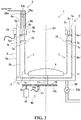
- FIG. 2 is a schematic view showing a structure of the washing machine 1 according to the embodiment.
- FIG. 3 is a partial longitudinal sectional perspective view of the washing machine 1 according to the embodiment.
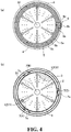
- FIG. 4 is a view showing a part of the washing machine 1 according to the embodiment when viewed from above.
- FIG. 4(a) is a top view
- FIG. 4(b) is a cross-sectional view of a dewatering tub 2 of the washing machine 1.
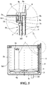
- FIG. 5 is a partial longitudinal sectional view of the washing machine 1 according to the embodiment.
- the washing machine 1 includes a washing machine main body 1a, an outer tub 3, a dewatering tub 2, a water receiving ring unit 5, a nozzle unit 6, a driving unit 40 and a control unit (see FIG. 6 ).
- the washing machine main body 1a shown in FIG. 1 has a substantially cuboid shape.
- An upper surface 10a of the washing machine main body 1a is formed with an opening 11 for placing laundry into/taking the laundry out of the outer tub 2, and an opening/closing lid 11a for opening or closing the opening 11.
- the outer tub 3 is a cylindrical member with a bottom, which is provided inside the washing machine main body 1a and is capable of storing washing water therein.
- an acceleration sensor 12 for detecting accelerations in both the horizontal and vertical directions is mounted on an outer peripheral surface 3a of the outer tub 3.
- the dewatering tub 2 is a cylindrical member with a bottom, which is disposed within the outer tub 3 and is coaxially with the outer tub 3.
- the dewatering tub 2 is supported so that the dewatering tub 2 rotates within the outer tub 3.
- the dewatering tub 2 accommodates the laundry therein, and a wall surface 2a thereof has a plurality of water-passing holes 2b (see FIG. 3 ).
- An impeller (stirring blade) 4 is rotatably disposed at the center of a bottom 2c of the dewatering tub 2. As shown in FIG. 3 , the impeller 4 has a substantially disk-shaped impeller main body 4b, a plurality of upper blades 4c formed on the upper surface of the impeller main body 4b, and a plurality of lower blades 4a formed on the lower surface of the impeller main body 4b. Such an impeller 4 is used to stir the washing water stored in the outer tub 3 to generate a water flow.
- each of the baffles 7 is formed to extend vertically from the bottom 2c of the dewatering tub 2 to the upper end thereof, and project from the inner peripheral surface 2a1 of the dewatering tub 2 toward axis S1.
- each of the baffles 7 is hollow, and has an arc cross section.
- each of the baffles 7 has a shape that the baffle slightly protrudes to the axis S1 of the dewatering tub 2 and spreads along the circumferential direction of the dewatering tub 2, thereby preventing the storage space of the dewatering tub 2 from being narrowed.
- an opening 71 is formed at the lower end of such a baffle 7.
- the opening 71 is opened in the vicinity of the bottom 2c of the dewatering tub 2, more specifically, below the impeller main body 4b.
- a horizontally elongated water circulation opening 70 is formed at the upper end of each baffle 7. Therefore, during the washing process in a state where a drain valve 50a (see FIG. 2 ) is closed and the washing water is accumulated in the outer tub 3, the washing water stirred by the lower blade 4a of the impeller 4 enters from the opening 71, ascends in the baffles 7, and is discharged from the water circulation opening 70 to rinse the laundry, as shown by an arrow in FIG. 3 .
- each of the baffles 7 is configured to circulate the washing water.
- the water pipe section described above which has the opening 71 and the water circulation opening 70 and can rinse the laundry is also applicable to the conventional washing machine. However, in the conventional washing machine, only one water pipe section is provided.
- a spacer 7a is formed inside each baffle 7.
- the spacer 7a extends from a position to which the communication members 5a1, 5b1 and 5c1 (described later) are connected and the water circulation opening 70 to a position close to the inner peripheral surface 2a1 of the dewatering tub 2.
- the spacer 7a extends from the upper end edge of the water circulation opening 70, and a free end 7a1 side thereof is bent downward.
- a gap 7b (see FIG. 2 ) is formed between the free end 7a1 of the spacer 7a and the inner peripheral surface 2a1 of the dewatering tub 2, and adjusting water (described later) supplied from the water receiving ring unit 5 flows downward through the gap 7b.
- the water receiving ring unit 5 is a member formed by stacking annular water guiding grooves 5a, 5b, 5c, which are opened upward, as three layers in the radial direction toward the axis S1 of the dewatering tub 2 (see FIG. 4 (a) ). As shown in FIG. 3 , the water receiving ring unit 5 is fixed to the upper end of the inner peripheral surface 2a1 of the dewatering tub 2.
- the number of the water guiding grooves 5a, 5b, and 5c is set to be the same as that of the baffles 7, and a water passage for allowing the adjusting water to flow to any one of the baffles 7 is formed inside the water guiding grooves 5a, 5b and 5c.
- Such a water receiving ring unit 5 has substantially the same size and shape as those of a known liquid balancer attached to a conventional washing machine.
- the water receiving ring unit is installed at a mounting position of a conventional liquid balancer to replace the liquid balancer.
- the liquid balancer has a function of passively eliminating the unbalance of the dewatering tub 2 during the dewatering.
- the liquid balancer has less effect.
- the water receiving ring unit 5 is connected to the upper end of the baffles 7 through the communication members 5a1, 5b1 and 5c1 respectively.
- the communication members 5a1, 5b1 and 5c1 are connected to the baffles 7 at a position above the water circulation opening 70.
- the nozzle unit 6 is a unit for injecting adjusting water into the water guiding grooves 5a, 5b and 5c individually.
- the nozzle unit 6 includes three water injection nozzles 6a, 6b and 6c arranged above the water guiding grooves 5a, 5b and 5c, and water supply valves 26a, 26b and 26c connected to the water injection nozzles 6a, 6b and 6c respectively.
- the number of the water injection nozzles 6a, 6b and 6c is set to be the same as the number of the water guiding grooves 5a, 5b and 5c, and the water injection nozzles are arranged at positions where water can be injected into respective water guiding grooves 5a, 5b and 5c.
- the tap water may be used as the adjusting water.
- a reversing water supply valve may also be employed as the water supply valves 26a, 26b and 26c.
- the adjusting water injected into the water guiding grooves 5a, 5b and 5c of the water receiving ring unit 5 from any one of the water injection nozzles 6a, 6b and 6c of the nozzle unit 6 flows into the baffle 7.
- the adjusting water flows into the baffle 7 from the water guiding groove 5c through the communication member 5c1, as indicated by an arrow in FIG. 5 .
- each of the baffles 7 has a pocket baffle structure capable of storing the adjusting water through the centrifugal force.
- the driving unit 40 shown in FIG. 2 is configured to cause pulleys 15, 15 and a transmission belt 15b to rotate by a motor 10, so as to cause a driving shaft 17 protruding toward the bottom 2c of the dewatering tub 2 to rotate. Accordingly, a driving force is applied to the dewatering tub 2 and the impeller 4 to make them rotate. In the washing machine 1, only the impeller 4 is caused to rotate during the washing process, while the dewatering tub 2 and the impeller 4 are caused to rotate integrally at a high speed during the dewatering process.
- a proximity switch 14 is provided in the vicinity of one of the pulleys 15. The proximity switch 14 is configured to detect passing of a mark 15a formed on the pulley 15.
- the washing machine 1 includes a dewatering tub 2 having an impeller 4 arranged at a bottom 2c thereof; three or more baffles 7 served as water pipe sections, the baffles are arranged on an inner circumferential surface 2a1 of the dewatering tub 2 at equal intervals along the circumferential direction of the inner circumferential surface 2a1, and are opened in the vicinity of the bottom 2c and formed with a water circulation opening 70 at the upper end thereof; a water receiving ring unit 5 fixed to the upper end of the dewatering tub 2 and formed by stacking a plurality of annular water guiding grooves 5a, 5b and 5c, the annular water guiding grooves 5a, 5b and 5c are connected to the upper end of each of the baffles 7 via communication members 5a1, 5b1 and 5c1 respectively; and a nozzle unit 6 for injecting adjusting water into each of the water guiding grooves 5a, 5b and 5c individually.
- the washing water is stirred upward by the lower blade 4a of the impeller 4, enters from the opening 71, passes through the baffles 7, and is discharged from the water circulation opening 70. Accordingly, the laundry is rinsed by the washing water circulating in the dewatering tub 2.
- the adjusting water is injected into any one of the water guiding grooves 5a, 5b and 5c of the water receiving ring unit 5, which rotates integrally with the dewatering tub 2, from the nozzle unit 6 individually, and then supplied to the baffles 7 via the communication members 5a1, 5b1 and 5c1, and is retained in the baffles 7 by the centrifugal force against the inner peripheral surface 2a1 of the dewatering tub 2. Therefore, the weight of the baffles 7 can be adjusted.
- the adjusting water in the baffles 7 is discharged from the opening 71 as the lower opening of the baffles 7 at the end of the dewatering process when the centrifugal force is reduced.
- the communication members 5a1, 5b1 and 5c1 are connected above the water circulation opening 70, and each of the baffles 7 has the spacer 7a extending from a space between the positions, to which c the 5a1, 5b1 and 5c1 are connected, and the water circulation opening 70 to a position close to the inner peripheral surface 2a1 of the dewatering tub 2. Therefore, during the washing process, the washing water stirred upward by the impeller 4 is prevented from entering the communication members 5a1, 5b1, 5c1 and the water guiding grooves 5a, 5b, 5c, and the washing water is guided by the spacer 7a so that it can be properly discharged from the water circulation opening 70.
- the adjusting water supplied from the water receiving ring unit 5 stably flows into each of the baffles 7 through the gap 7b between the spacer 7a and the inner peripheral surface 2a1 of the dewatering tub 2.
- the water receiving ring unit 5 is disposed on the inner peripheral surface 2a1 of the dewatering tub 2.
- the water receiving ring unit 5 is formed by stacking the plurality of water guiding grooves 5a, 5b and 5c in the radial direction of the dewatering tub 2, so that the water guiding grooves 5a, 5b and 5c are opened upward to easily receive water separately injected into each of the water guiding grooves 5a, 5b and 5c from the nozzle unit 6.
- FIG. 6 is a block diagram showing the electrical configuration of the washing machine 1 according to the present embodiment.
- the operation of the washing machine 1 is controlled by a control unit 30 including a microcomputer.
- the control unit 30 includes a central control unit (CPU) 31 for controlling the overall system.
- the CPU 31 is connected to a memory 32 for storing the following values necessary for the rotation control of the dewatering tub 2: a low speed rotation setting value (N1) before the dewatering operation is started; a high-speed rotation setting value (N2) after the dewatering operation is started; an imbalance amount setting value (ma) during the low-speed dewatering operation and an imbalance amount setting value (mb) during the high-speed dewatering operation.
- programs stored in the memory 32 are executed by a microcomputer to carry out a preset operation.
- data and the like used for executing the programs are temporarily stored in the memory 32.
- the central control unit 31 is configured to output a control signal to a rotation speed control unit 33.
- the control signal is further output to a motor control unit (motor control circuit) 34 to control the rotation of the motor 10.
- the rotation speed control unit 33 receives a signal indicating the rotation speed of the motor 10 from the motor control unit 34 in real time, and the signal is used as a control element.
- An acceleration sensor 12 is connected to an unbalance amount detector 35, and the acceleration sensor 12 and the proximity switch 14 are connected to an unbalance position detector 36.
- an unbalance amount (M) is calculated by the unbalance amount detector 35 based on the magnitudes of the accelerations in the horizontal and vertical directions from the acceleration sensor 12, and the unbalance amount is output to an unbalance amount determination unit 37.
- the unbalance position detector 36 calculates an angle in the unbalance direction based on a signal indicating the position of the mark 15a input from the proximity switch 14, and a signal indication the unbalance position is output to a water injection controller 38.
- the water injection controller 38 determines whether to supply water to any one of the baffle 7 in the dewatering tubs 2 and determines the supplying amount thereof based on the control programs stored in advance. Then, the selected water supply valves 26a, 26b and 26c are opened to inject the adjusting water.
- the adjusting water is injected into the water guiding grooves 5a, 5b and 5c of the water receiving ring unit 5 from the water supply nozzles 6a, 6b and 6c selected based on the calculation of the unbalance amount.
- the injection of the adjusting water is stopped.
- the water injection controller 38 performs control to supply the adjusting water to the baffle 7(A).
- the water injection controller 38 performs control to supply the adjusting water to both of the baffle 7(B) and the baffle 7(C).
- FIGs. 7-8 are flowcharts showing the control of the washing machine 1 according to the present embodiment.
- the central control unit 31 when the central control unit 31 receives an input signal from a dewatering button (not shown) or receives a signal for activating the dewatering process during the washing mode operation, the process proceeds to step SP1 to start the dewatering process.
- step SP1 the central control unit 31 performs control to cause the dewatering tub 2 to reverse slowly, and then cause the dewatering tub 2 to accelerate.
- step SP2 the central control unit 31 performs control to rotate the dewatering tub 2 at a low speed based on the low-speed rotation setting value (N1).
- step SP3 the central control unit 31 performs control to detect the unbalance amount (M) based on the acceleration value (x-component of the acceleration sensor) given by the acceleration sensor 12.
- step SP4 the central control unit 31 performs control to compare the unbalance amount (M) with the unbalance amount setting value (ma) stored in the memory 32 to determine whether M is less than ma.
- the process proceeds to step SP6.
- the unbalance amount setting value (ma) is a threshold value indicating that the bias of the laundry is too large to be eliminated even if the adjusting water is supplied to the baffles 7. That is, SP5 is carried out if it is determined that the bias of the laundry is too large to be eliminated even if the adjusting water is supplied to the baffles 7.
- step SP5 the central control unit 31 performs control to stop the rotation of the dewatering tub 2, and after that, the process returns to step SP1 to repeat steps SP1 ⁇ SP4.
- step SP6 if the central control unit 31 determines that the time elapsed since the start of the low-speed rotation of the dewatering tub 2 is equal to or greater than a preset time for performing the low-speed rotation, the process proceeds to step SP7.
- step SP7 the central control unit 31 performs control based on the high-speed rotation setting value (N2) to rotate the dewatering tub 2 at a high speed.
- step SP8 the central control unit 31 performs control based on the acceleration value given by the acceleration sensor 12 to detect the unbalance amount (M) and the unbalance position (N).
- step SP9 based on the unbalance position (N), the central control unit 31 replaces the water supply valve X, the region Y and the water supply valve Z shown in FIG. 9 with the values in the parameter table.
- FIG. 9 is a diagram for explaining the control flows in the dewatering process of the washing machine 1.
- the cross section of the dewatering tub 2 is equally divided into six parts in the circumferential direction, and the positional relationship with the baffles 7 is schematically shown.
- the baffle 7 indicated by 7(A) is a baffle 7 to which the adjusting water is supplied from the water injection nozzle 6a shown in FIGs. 2 and 5 .
- the baffle 7 indicated by 7(B) is a baffle 7 to which the adjusting water is supplied from the water injection nozzle 6b shown in FIGs. 2 and 5
- the baffle 7 indicated by 7(C) is a baffle 7 to which the adjusting water is supplied from the water injection nozzle 6c shown in FIGs. 2 and 5 .
- step SP10 the central control unit 31 performs control to open the water supply valve X described in the parameter table of FIG. 9 .
- the water supply valve X is the water supply valve 26c corresponding to the baffle 7(C) opposed to region I. Therefore, the adjusting water is supplied to the baffle 7 corresponding to the water supply valve X, and the amount and the position of the eccentric load change.
- step SP11 shown in FIG. 8 the central control unit 31 performs control to recalculate the unbalance amount (M) and the unbalance position (N) based on the acceleration value given by the acceleration sensor 12.
- step SP12 the central control unit 31 performs control to compare the unbalance amount (M) with the unbalance amount setting value (ma) stored in the memory 32, so as to determine whether M is less than ma. If it is determined that M is less than ma, the process proceeds to step SP13. On the other hand, if it is determined that M is not less than ma, the process proceeds to step SP21 described later. That is, if it is determined that the bias of the laundry is too large to be eliminated even if the adjusting water is supplied to the baffle 7, the process proceeds to step SP21.
- step SP13 the central control unit 31 performs control to compare the unbalance amount (M) with the unbalance amount setting value (mb) stored in the memory 32, so as to determine whether M is less than mb. If it is determined that M is less than mb, the process proceeds to step SP23 described later. On the other hand, when it is determined that M is not less than mb, the process proceeds to step SP14.
- the unbalance amount setting value (mb) is a value smaller than the unbalance amount setting value (ma), and is a threshold indicating that no noise will occur even if no adjusting water is supplied to the baffle 7 because the bias of the laundry is very little. That is, when it is determined that the eccentric load is small or absent, no noise will occur even if no water is supplied to the baffle 7, and the process proceeds to step SP23.
- step SP14 when the central control unit 31 determines that the time elapsed since the water supply valve X is opened is equal to or greater than a preset time, the process proceeds to step SP15.
- the preset time is the time required for filling one of the baffles 7 with the adjusting water.
- step SP15 the central control unit 31 determines whether the unbalance position (N) is the region Y shown in the parameter table of FIG. 9 . If it is determined that the unbalance position (N) is the region Y, the process proceeds to step SP16. If it is determined that the unbalance position (N) is not the region Y, the process returns to step SP11. For example, if the initial unbalance position (N) in step SP11 is region I, then the unbalance position (N) is always the region I as long as no recalculation is performed, thus the process returns to step SP16.
- step SP16 Since the result of the recalculation in step SP16 changes with time due to the water supply from the water supply valve X, the unbalance position (N) changes from the region I to the region V when the weight of the baffle 7 corresponding to the water supply valve 26c increases.
- step SP15 is repeated for a plurality of times, the unbalance position (N) becomes the region Y.
- step SP16 the central control unit 31 performs control to close the water supply valve X described in the parameter table of FIG. 9 and open the water supply valve Z.
- the water supply valve X is the water supply valve 26c corresponding to the baffle 7 opposed to the region I
- the water supply valve Z is the water supply valve 26b corresponding to the baffle 7(B).
- the baffle 7(B) is located closer to the region I than the baffle 7(C) corresponding to the water supply valve 26c.
- the adjusting water is supplied to the baffle 7 corresponding to the water supply valve Z, and the amount and the position of the eccentric load change.
- step SP17 the central control unit 31 performs control to recalculate the unbalance amount (M) and the unbalance position (N) based on the acceleration value given by the acceleration sensor 12.
- step SP18 the central control unit 31 performs control to compare the unbalance amount (M) with the unbalance amount setting value (ma) stored in the memory 32, so as to determine whether M is less than ma. If it is determined that M is less than ma, the process proceeds to step SP19. On the other hand, if it is determined that M is not less than ma, the process proceeds to step SP21 described later. That is, if it is determined that the bias of the laundry is too large to be eliminated even if more adjusting water is supplied to the baffle 7, the process proceeds to step SP21.
- step SP19 the central control unit 31 performs control to compare the unbalance amount (M) with the unbalance amount setting value (mb) stored in the memory 32, so as to determine whether M is less than mb. If it is determined that M is less than mb, the process proceeds to step SP23 described later. That is, when it is determined that, by supplying the water to the baffle 7, the eccentric load is eliminated so that no noise occurs, the process proceeds to step SP23. On the other hand, when it is determined that M is not less than mb, the process proceeds to step SP20.
- step SP20 when the central control unit 31 determines that the time elapsed since the water supply valve Z is opened is equal to or greater than a preset time, the process proceeds to step SP21 described later. On the other hand, when it is determined that the time elapsed since the water supply valve Z is opened is less than the preset time, the process returns to step SP17.
- step SP21 shown in FIG. 7 the central control unit 31 performs control to close all of the water supply valves X, Z.
- step SP22 the central control unit 31 performs control to stop the rotation of the dewatering tub 2, and then the process returns to step SP1.
- step SP23 shown in FIG. 8 the central control unit 31 performs control to close all of the water supply valves X and Z.
- step SP24 the central control unit 31 performs control to rotate the dewatering tub 2 at the maximum revolution for a predetermined period to perform the dewatering process. Then, the dewatering process is completed.
- the clothes stick to the inner peripheral surface 2a1 of the dewatering tub 2 by the centrifugal force, and the dewatering tub 2 is accelerated to a set rotation speed lower than the rotation speed of the dewatering rotation.
- the clothes are not uniformly dispersed in the dewatering tub 2, a circular orbital vibration is generated in the outer tub 3 due to the unbalance amount (M).
- the value of the acceleration sensor 12 is sinusoidal in accordance with the rotation of the dewatering tub 2.
- the microcomputer calculates the magnitude of the unbalance (M) and the angle from the position of the marker 15a. As long as the unbalance amount (M) detected is equal to or greater than the set value, water is injected to the baffle 7 at its symmetrical position.
- the baffle 7 into which the adjusting water is injected varies depending on the unbalance position (N).
- water is only supplied to the baffle 7 which is farthest away from the initial unbalance position (N) detected and has a greater influence on the adjustment of the unbalance amount (M) and the position (N).
- water is injected into another baffle 7 as necessary while taking into consideration changes in the unbalance amount (M) and the position (N) due to the supplying of water.
- the dewatering tub 2 is accelerated to a high-speed to perform the dewatering.
- the centrifugal force is less than the gravitational acceleration, the adjusting water in the baffle 7 flows out of the lower portion from the opening 71 and is discharged.
- the washing machine 1 capable of preventing the vibrations and noises in any processes ranging from the start to the termination of the dewatering process can be provided.
- the adjusting water is injected into any one of the water guiding grooves 5a (5b, 5c) of the water receiving ring unit 5 from the nozzle unit 6, and is supplied to the baffle 7 via the communication member 5a1 (5b1, 5c1). Therefore, even if there is a bias of the laundry in the dewatering tub 2 during the dewatering process, the imbalance of the dewatering tub 2 can be eliminated while the dewatering tub 2 continues to rotate without slowing or stopping the rotation of the dewatering tub halfway. Accordingly, the vibrations and the noises caused by the eccentricity of the dewatering tub 2 can be suppressed.
- the structure of the embodiment is not limited to the above structure, and various deformations can be made.
- the water receiving ring unit 5 is formed by three water guiding grooves 5a, 5b and 5c, and three baffles 7 are provided correspondingly.
- the present disclosure is not limited to this, as long as the number of the baffles 7 is set to be three or more and the number of the water guiding grooves is set to be the same as that of the baffles 7.
- the water receiving ring unit 5 may have a structure in which the plurality of water guiding grooves 5a, 5b and 5c are vertically stacked, thereby reducing the lateral width of the water receiving ring unit 5 and enlarging the opening of the dewatering tub 2.
- the baffle 7 may have a shape that becomes widened upward or downward.
Landscapes
- Engineering & Computer Science (AREA)
- Textile Engineering (AREA)
- Main Body Construction Of Washing Machines And Laundry Dryers (AREA)
- Control Of Washing Machine And Dryer (AREA)
- Detail Structures Of Washing Machines And Dryers (AREA)
Abstract
Description
- The present application relates to a washing machine and a method for controlling the washing machine capable of eliminating the unbalance of a dewatering tub and suppressing vibrations and noises caused due to eccentricity of the dewatering tub at the time of dewatering while keeping the rotation of the dewatering tub.
- For a general washing machine installed in a common home or a laundromat, the laundry will be biased in a dewatering tub during dewatering, causing vibrations and noises. Depending on the location of the washing machine and the surrounding environment thereof, troubles may occur due to the vibrations and the noises. In addition, when the laundry is greatly biased during the dewatering, the eccentricity of the dewatering tub during the rotation becomes greater, and thus a large torque is required for the rotation. Accordingly, the dewatering operation cannot be started.
- In view of the above,
Patent Literature 1 discloses the following technique: an unbalance amount and an unbalance position of the laundry inside the washing tub are detected during the dewatering; when there is imbalance, the washing tub is braked to stop rotating to reduce the centrifugal force so that a mass of laundry causing the imbalance drops and is dispersed by gravity. - In addition,
Patent Document 2 discloses the following technique: it is determined whether there is imbalance in the washing/dewatering tub during a low-speed rotation; when the imbalance is detected, to eliminate the imbalance, the motor is stopped, and water is injected to the washing/dewatering tub to release the mass of laundry. - However, for the configuration disclosed in
Patent Document 1, unbalance detection and dispersion operation are performed only when the dewatering tub is rotated at a low speed, and there is a possibility that the unbalance may occur again due to factors such as the type of the laundry after a high speed rotation of the dewatering tub is started. - Moreover, for the configurations disclosed in
Patent Literatures Patent Document 2, in addition to the increase in power consumption, a problem that the amount of water used increases exists. -
- Patent Literature 1: Japanese Laid-Open Patent Publication No.
9-290089 - Patent Literature 2: Japanese Patent Publication No.
5650927 - The present disclosure aims to effectively solve such a problem and provide a washing machine and a method for controlling the same. Through the washing machine and the method for controlling the same, the upsizing and complication of the apparatus can be effectively suppressed by utilizing the structure of the existing washing machine, and the unbalance of the dewatering tub can be eliminated without decelerating or stopping the rotation even if the laundry is biased in the dewatering tub during a dewatering operation. Therefore, the vibrations and the noises caused due to eccentricity of the dewatering tub are suppressed.
- The present disclosure has been made in view of the above problem.
- The washing machine according to the present disclosure includes: a dewatering tub, which has an impeller arranged at a bottom thereof; three or more water pipe sections, which are arranged at equal intervals in a circumferential direction with respect to an inner circumferential surface of the dewatering tub, and are opened in the vicinity of the bottom, a water circulation opening is formed at the upper end of each of the water pipe sections; a water receiving ring unit, which is fixed to the upper end of the dewatering tub and formed by stacking a plurality of annular water guiding grooves, which are connected to the upper end of the respective water pipe sections via a communication member; and a nozzle unit capable of individually injecting adjusting water into each of the water guiding grooves.
- Particularly, it is preferable, that the communication member is connected to a position above the water circulation opening, and each of the water pipe sections is provided with a spacer extending from a position to which the communication member is connected and the water circulation opening to a position close to the inner circumferential surface of the dewatering tub.
- Further, preferably, the water receiving ring unit is provided at the inner circumferential surface of the dewatering tub, and is formed by stacking the plurality of water guiding grooves in a radial direction of the dewatering tub.
- Alternatively, preferably, the water receiving ring unit is provided at the inner circumferential surface of the dewatering tub, and is formed by stacking the plurality of water guiding grooves in an up-down direction.
- Further, the present disclosure relates to a method for controlling the washing machine. During a dewatering process, the adjusting water is injected into any of the water guiding grooves of the water receiving ring unit from the nozzle unit, and is supplied to the water pipe sections via the communication member.
- According to the present disclosure explained above, during the washing process, the washing water is stirred upward by the impeller, enters the opening near the bottom and passes through the water pipe sections to be discharged from the water circulation opening. Therefore, through the washing water circulated inside the dewatering tub, the laundry is rinsed in the same manner as the conventional washing machine. In addition, in the dewatering process, the adjusting water can be individually injected into any of the water receiving ring units that rotate integrally with the dewatering tub from the nozzle unit, so as to supply the adjusting water to the water pipe sections via the communication members, and by means of the centrifugal force, the adjusting water is stuck to the inner circumferential surface of the dewatering tub to be left inside the water pipe sections to adjust the weight of the water pipe sections. Therefore, by keeping the adjusting water in the water pipe section on the side opposite to the part, where the clothes are biased, with respect to the axis of the dewatering tub during the dewatering driving, it is possible to eliminate the imbalance of the dewatering tub caused by the bias of the laundry without slowing or stopping the rotation of the dewatering tub halfway. Therefore, the present disclosure can efficiently suppress upsizing and complication of the apparatus by utilizing the structure of the existing washing machine, and even if the laundry is biased in the dewatering tub during a dewatering operation, the imbalance of the dewatering tub can be eliminated while the dewatering tub continues to rotate, and the vibrations (vibrations occurring during the dewatering operation) and the noises that are generated by the biasing of the dewatering tub can be inhibited.
- In particular, according to the present disclosure having the spacer, the washing water stirred upward by the impeller is guided through the spacer during the washing process so as to be discharged from the water circulation opening properly. In addition, during the dewatering process, the adjusting water supplied via the water receiving ring unit is supplied stably from the gap between the spacer and the inner circumferential surface of the dewatering tub to the lower portion of the water pipe sections.
- Further, according to the present disclosure in which a plurality of water guiding grooves are stacked in a radial direction of the dewatering tub, all the water guiding grooves are opened upward, and the water can be individually injected from the nozzle unit to each of the water guiding grooves.
- Alternatively, according to the present disclosure in which the plurality of water guiding grooves are vertically stacked, the lateral width of the water receiving ring unit can be reduced, and the opening of the dewatering tub can be widened.
- In addition, according to the present disclosure that is controlled by supplying the adjusting water to the water pipe sections during the dewatering process, even if the laundry is biased inside the dewatering tub during the dewatering operation, it is possible to eliminate the imbalance of the dewatering tub in a state where the normal dewatering operation continues, and suppress the vibrations and the noises caused by the centrifugation of the dewatering tub without slowing or stopping the rotation of the dewatering tub halfway.
-
-
FIG. 1 is a perspective view showing an appearance of a washing machine according to an embodiment of the present disclosure. -
FIG. 2 is a schematic view showing a structure of the washing machine. -
FIG. 3 is a partial longitudinal sectional perspective view of the washing machine. -
FIG. 4 is a view showing a part of the washing machine viewed from above. -
FIG. 5 is a partial longitudinal sectional view of the washing machine. -
FIG. 6 is a block diagram of an electrical system of the washing machine. -
FIG. 7 is a flowchart showing a control flow during the dewatering process of the washing machine. -
FIG. 8 is a flowchart showing a control flow during the dewatering process of the washing machine. -
FIG. 9 is a diagram for explaining the control flow during the dewatering process of the washing machine. -
- 1: Washing machine; 2: Dewatering tub; 2a1: Inner circumferential surface of the dewatering tub; 2c: Bottom; 4: Impeller; 5: Water receiving ring unit; 5a, 5b, 5c: Water guiding groove; 5a1, 5b1 and 5c1: Communication member; 6: Nozzle unit; 7: Baffle (water pipe section); 7a: Spacer; 70: Water circulation opening; 71: Opening (opening)
- Hereinafter, an embodiment of the present disclosure will be described in detail in accompanying with the drawings.
-
FIG. 1 is a perspective view showing an appearance of a vertical type washing machine 1 (hereinafter, it is referred to as "a washing machine") according to an embodiment of the present disclosure.FIG. 2 is a schematic view showing a structure of thewashing machine 1 according to the embodiment.FIG. 3 is a partial longitudinal sectional perspective view of thewashing machine 1 according to the embodiment.FIG. 4 is a view showing a part of thewashing machine 1 according to the embodiment when viewed from above.FIG. 4(a) is a top view, andFIG. 4(b) is a cross-sectional view of adewatering tub 2 of thewashing machine 1.FIG. 5 is a partial longitudinal sectional view of thewashing machine 1 according to the embodiment. - The
washing machine 1 according to the embodiment includes a washing machinemain body 1a, anouter tub 3, adewatering tub 2, a water receivingring unit 5, anozzle unit 6, adriving unit 40 and a control unit (seeFIG. 6 ). - The washing machine
main body 1a shown inFIG. 1 has a substantially cuboid shape. Anupper surface 10a of the washing machinemain body 1a is formed with anopening 11 for placing laundry into/taking the laundry out of theouter tub 2, and an opening/closing lid 11a for opening or closing theopening 11. - The
outer tub 3 is a cylindrical member with a bottom, which is provided inside the washing machinemain body 1a and is capable of storing washing water therein. As shown inFIG. 2 , anacceleration sensor 12 for detecting accelerations in both the horizontal and vertical directions is mounted on an outerperipheral surface 3a of theouter tub 3. - The dewatering
tub 2 is a cylindrical member with a bottom, which is disposed within theouter tub 3 and is coaxially with theouter tub 3. The dewateringtub 2 is supported so that thedewatering tub 2 rotates within theouter tub 3. Thedewatering tub 2 accommodates the laundry therein, and awall surface 2a thereof has a plurality of water-passingholes 2b (seeFIG. 3 ). - An impeller (stirring blade) 4 is rotatably disposed at the center of a bottom 2c of the
dewatering tub 2. As shown inFIG. 3 , theimpeller 4 has a substantially disk-shaped impellermain body 4b, a plurality ofupper blades 4c formed on the upper surface of the impellermain body 4b, and a plurality oflower blades 4a formed on the lower surface of the impellermain body 4b. Such animpeller 4 is used to stir the washing water stored in theouter tub 3 to generate a water flow. - As shown in
FIGs. 3 and4(b) , on the inner peripheral surface 2a1 of thedewatering tub 2, three baffles (water injection pipes) 7 are provided as water pipe sections at equal intervals (at equal angles) in the circumferential direction. Each of thebaffles 7 is formed to extend vertically from the bottom 2c of thedewatering tub 2 to the upper end thereof, and project from the inner peripheral surface 2a1 of thedewatering tub 2 toward axis S1. In addition, each of thebaffles 7 is hollow, and has an arc cross section. In this manner, each of thebaffles 7 has a shape that the baffle slightly protrudes to the axis S1 of thedewatering tub 2 and spreads along the circumferential direction of thedewatering tub 2, thereby preventing the storage space of thedewatering tub 2 from being narrowed. - As shown in
FIGs. 2∼3 , anopening 71 is formed at the lower end of such abaffle 7. Theopening 71 is opened in the vicinity of the bottom 2c of thedewatering tub 2, more specifically, below the impellermain body 4b. In addition, a horizontally elongatedwater circulation opening 70 is formed at the upper end of eachbaffle 7. Therefore, during the washing process in a state where adrain valve 50a (seeFIG. 2 ) is closed and the washing water is accumulated in theouter tub 3, the washing water stirred by thelower blade 4a of theimpeller 4 enters from theopening 71, ascends in thebaffles 7, and is discharged from thewater circulation opening 70 to rinse the laundry, as shown by an arrow inFIG. 3 . In addition, the washing water is circulated in thedewatering tub 2 by repeating this action. That is, each of thebaffles 7 is configured to circulate the washing water. It should be noted that the water pipe section described above which has theopening 71 and thewater circulation opening 70 and can rinse the laundry is also applicable to the conventional washing machine. However, in the conventional washing machine, only one water pipe section is provided. - Further, a
spacer 7a is formed inside eachbaffle 7. Thespacer 7a extends from a position to which the communication members 5a1, 5b1 and 5c1 (described later) are connected and thewater circulation opening 70 to a position close to the inner peripheral surface 2a1 of thedewatering tub 2. Thespacer 7a extends from the upper end edge of thewater circulation opening 70, and a free end 7a1 side thereof is bent downward. Agap 7b (seeFIG. 2 ) is formed between the free end 7a1 of thespacer 7a and the inner peripheral surface 2a1 of thedewatering tub 2, and adjusting water (described later) supplied from the waterreceiving ring unit 5 flows downward through thegap 7b. - The water
receiving ring unit 5 is a member formed by stacking annularwater guiding grooves FIG. 4 (a) ). As shown inFIG. 3 , the waterreceiving ring unit 5 is fixed to the upper end of the inner peripheral surface 2a1 of thedewatering tub 2. The number of thewater guiding grooves baffles 7, and a water passage for allowing the adjusting water to flow to any one of thebaffles 7 is formed inside thewater guiding grooves receiving ring unit 5 has substantially the same size and shape as those of a known liquid balancer attached to a conventional washing machine. In the present embodiment, the water receiving ring unit is installed at a mounting position of a conventional liquid balancer to replace the liquid balancer. The liquid balancer has a function of passively eliminating the unbalance of thedewatering tub 2 during the dewatering. However, as described later, compared with the waterreceiving ring unit 5 which can actively eliminate the unbalance of thedewatering tub 2, the liquid balancer has less effect. - The water
receiving ring unit 5 is connected to the upper end of thebaffles 7 through the communication members 5a1, 5b1 and 5c1 respectively. The communication members 5a1, 5b1 and 5c1 are connected to thebaffles 7 at a position above thewater circulation opening 70. - The
nozzle unit 6 is a unit for injecting adjusting water into thewater guiding grooves nozzle unit 6 includes threewater injection nozzles water guiding grooves water supply valves water injection nozzles water injection nozzles water guiding grooves water guiding grooves water supply valves - When such a configuration is adopted, during the dewatering process in which the
drain valve 50a is opened and the washing water in theouter tub 3 is discharged from thedrain port 50, the adjusting water injected into thewater guiding grooves receiving ring unit 5 from any one of thewater injection nozzles nozzle unit 6 flows into thebaffle 7. For example, in the case that the adjusting water is injected from theinjection nozzle 6c, the adjusting water flows into thebaffle 7 from thewater guiding groove 5c through the communication member 5c1, as indicated by an arrow inFIG. 5 . When thedewatering tub 2 is in a high-speed rotation state, the adjusting water flowing into thebaffles 7 is retained by the centrifugal force against the inner peripheral surface 2a1 of thedewatering tub 2. As a result, the weight of thebaffles 7 increases, and the balance of thedewatering tub 2 is changed. In this way, each of thebaffles 7 has a pocket baffle structure capable of storing the adjusting water through the centrifugal force. When the dewatering process is nearly completed and the rotational speed of thedewatering tub 2 is reduced, the centrifugal force in thebaffles 7 gradually attenuates so that the adjusting water flows out of theopening 71 by gravity and is discharged to the outside of theouter tub 3 through thedrain port 50. At this time, the adjusting water flows into the lower portion of the impellermain body 4b through theopening 71. Therefore, the adjusting water is discharged without wetting the clothes located above the impellermain body 4b. - The driving
unit 40 shown inFIG. 2 is configured to causepulleys transmission belt 15b to rotate by amotor 10, so as to cause a drivingshaft 17 protruding toward the bottom 2c of thedewatering tub 2 to rotate. Accordingly, a driving force is applied to thedewatering tub 2 and theimpeller 4 to make them rotate. In thewashing machine 1, only theimpeller 4 is caused to rotate during the washing process, while thedewatering tub 2 and theimpeller 4 are caused to rotate integrally at a high speed during the dewatering process. In addition, aproximity switch 14 is provided in the vicinity of one of thepulleys 15. Theproximity switch 14 is configured to detect passing of amark 15a formed on thepulley 15. - As described above, the
washing machine 1 according to the present embodiment includes adewatering tub 2 having animpeller 4 arranged at a bottom 2c thereof; three ormore baffles 7 served as water pipe sections, the baffles are arranged on an inner circumferential surface 2a1 of thedewatering tub 2 at equal intervals along the circumferential direction of the inner circumferential surface 2a1, and are opened in the vicinity of the bottom 2c and formed with awater circulation opening 70 at the upper end thereof; a waterreceiving ring unit 5 fixed to the upper end of thedewatering tub 2 and formed by stacking a plurality of annularwater guiding grooves water guiding grooves baffles 7 via communication members 5a1, 5b1 and 5c1 respectively; and anozzle unit 6 for injecting adjusting water into each of thewater guiding grooves - When such a configuration is adopted, during the washing process, the washing water is stirred upward by the
lower blade 4a of theimpeller 4, enters from theopening 71, passes through thebaffles 7, and is discharged from thewater circulation opening 70. Accordingly, the laundry is rinsed by the washing water circulating in thedewatering tub 2. In addition, during the dewatering process, the adjusting water is injected into any one of thewater guiding grooves receiving ring unit 5, which rotates integrally with thedewatering tub 2, from thenozzle unit 6 individually, and then supplied to thebaffles 7 via the communication members 5a1, 5b1 and 5c1, and is retained in thebaffles 7 by the centrifugal force against the inner peripheral surface 2a1 of thedewatering tub 2. Therefore, the weight of thebaffles 7 can be adjusted. Please note that, the adjusting water in thebaffles 7 is discharged from theopening 71 as the lower opening of thebaffles 7 at the end of the dewatering process when the centrifugal force is reduced. Therefore, during the dewatering driving, by keeping the adjusting water in thebaffle 7 on the side opposite to a position, where the laundry is biased, with respect to the axis S1 of thedewatering tub 2, it is possible to eliminate the imbalance of thedewatering tub 2 caused by the bias of the laundry without slowing or stopping the rotation of thedewatering tub 2 halfway. In this way, the upsizing and complication of the apparatus can be suppressed by utilizing the known structure for rinsing in the present disclosure, and even if the laundry is biased in the dewatering tub during a dewatering operation, the imbalance of thedewatering tub 2 can be eliminated in a state where thedewatering tub 2 continues to rotate. Therefore, the vibrations and the noises caused by the biasing of thedewatering tub 2 can be inhibited. In addition, troubles generated due to vibrations and noises are prevented in the placement of thewashing machine 1 and the surrounding environment thereof. - Moreover, as described above, the communication members 5a1, 5b1 and 5c1 are connected above the
water circulation opening 70, and each of thebaffles 7 has thespacer 7a extending from a space between the positions, to which c the 5a1, 5b1 and 5c1 are connected, and thewater circulation opening 70 to a position close to the inner peripheral surface 2a1 of thedewatering tub 2. Therefore, during the washing process, the washing water stirred upward by theimpeller 4 is prevented from entering the communication members 5a1, 5b1, 5c1 and thewater guiding grooves spacer 7a so that it can be properly discharged from thewater circulation opening 70. In addition, during the dewatering process, the adjusting water supplied from the waterreceiving ring unit 5 stably flows into each of thebaffles 7 through thegap 7b between thespacer 7a and the inner peripheral surface 2a1 of thedewatering tub 2. - Further, as described above, the water
receiving ring unit 5 is disposed on the inner peripheral surface 2a1 of thedewatering tub 2. The waterreceiving ring unit 5 is formed by stacking the plurality ofwater guiding grooves dewatering tub 2, so that thewater guiding grooves water guiding grooves nozzle unit 6. -
FIG. 6 is a block diagram showing the electrical configuration of thewashing machine 1 according to the present embodiment. The operation of thewashing machine 1 is controlled by acontrol unit 30 including a microcomputer. Thecontrol unit 30 includes a central control unit (CPU) 31 for controlling the overall system. TheCPU 31 is connected to amemory 32 for storing the following values necessary for the rotation control of the dewatering tub 2: a low speed rotation setting value (N1) before the dewatering operation is started; a high-speed rotation setting value (N2) after the dewatering operation is started; an imbalance amount setting value (ma) during the low-speed dewatering operation and an imbalance amount setting value (mb) during the high-speed dewatering operation. Further, through thecontrol unit 30, programs stored in thememory 32 are executed by a microcomputer to carry out a preset operation. Moreover, data and the like used for executing the programs are temporarily stored in thememory 32. - The
central control unit 31 is configured to output a control signal to a rotationspeed control unit 33. The control signal is further output to a motor control unit (motor control circuit) 34 to control the rotation of themotor 10. It should be noted that the rotationspeed control unit 33 receives a signal indicating the rotation speed of themotor 10 from themotor control unit 34 in real time, and the signal is used as a control element. Anacceleration sensor 12 is connected to anunbalance amount detector 35, and theacceleration sensor 12 and theproximity switch 14 are connected to anunbalance position detector 36. - Accordingly, when the
mark 15a (seeFIG. 2 ) is detected by theproximity switch 14, an unbalance amount (M) is calculated by theunbalance amount detector 35 based on the magnitudes of the accelerations in the horizontal and vertical directions from theacceleration sensor 12, and the unbalance amount is output to an unbalanceamount determination unit 37. On the other hand, theunbalance position detector 36 calculates an angle in the unbalance direction based on a signal indicating the position of themark 15a input from theproximity switch 14, and a signal indication the unbalance position is output to awater injection controller 38. - When a signal indicating the unbalance amount and the unbalance position from the unbalance
amount determination unit 37 and theunbalance position detector 36 is input, thewater injection controller 38 determines whether to supply water to any one of thebaffle 7 in thedewatering tubs 2 and determines the supplying amount thereof based on the control programs stored in advance. Then, the selectedwater supply valves dewatering tub 2 is unbalanced, the adjusting water is injected into thewater guiding grooves receiving ring unit 5 from thewater supply nozzles baffles 7, the injection of the adjusting water is stopped. - It should be noted that, for example, as shown in
FIG. 4(b) , when the mass of laundry LD (X) constituting the main factor of the imbalance is located between the baffle 7(B) and the baffle 7(C) of thedewatering tub 2, thewater injection controller 38 performs control to supply the adjusting water to the baffle 7(A). In addition, when the mass of laundry LD (Y) is in the vicinity of the baffle 7(A), thewater injection controller 38 performs control to supply the adjusting water to both of the baffle 7(B) and the baffle 7(C). -
FIGs. 7-8 are flowcharts showing the control of thewashing machine 1 according to the present embodiment. - In the present embodiment, when the
central control unit 31 receives an input signal from a dewatering button (not shown) or receives a signal for activating the dewatering process during the washing mode operation, the process proceeds to step SP1 to start the dewatering process. - In step SP1, the
central control unit 31 performs control to cause thedewatering tub 2 to reverse slowly, and then cause thedewatering tub 2 to accelerate. - In step SP2, the
central control unit 31 performs control to rotate thedewatering tub 2 at a low speed based on the low-speed rotation setting value (N1). - In step SP3, the
central control unit 31 performs control to detect the unbalance amount (M) based on the acceleration value (x-component of the acceleration sensor) given by theacceleration sensor 12. - In step SP4, the
central control unit 31 performs control to compare the unbalance amount (M) with the unbalance amount setting value (ma) stored in thememory 32 to determine whether M is less than ma. When it is determined that M is less than ma, the process proceeds to step SP6. On the other hand, when it is determined that M is not less than ma, the process proceeds to step SP5. Herein, the unbalance amount setting value (ma) is a threshold value indicating that the bias of the laundry is too large to be eliminated even if the adjusting water is supplied to thebaffles 7. That is, SP5 is carried out if it is determined that the bias of the laundry is too large to be eliminated even if the adjusting water is supplied to thebaffles 7. - In step SP5, the
central control unit 31 performs control to stop the rotation of thedewatering tub 2, and after that, the process returns to step SP1 to repeat steps SP1∼SP4. - In step SP6, if the
central control unit 31 determines that the time elapsed since the start of the low-speed rotation of thedewatering tub 2 is equal to or greater than a preset time for performing the low-speed rotation, the process proceeds to step SP7. - In step SP7, the
central control unit 31 performs control based on the high-speed rotation setting value (N2) to rotate thedewatering tub 2 at a high speed. - In step SP8, the
central control unit 31 performs control based on the acceleration value given by theacceleration sensor 12 to detect the unbalance amount (M) and the unbalance position (N). - In step SP9, based on the unbalance position (N), the
central control unit 31 replaces the water supply valve X, the region Y and the water supply valve Z shown inFIG. 9 with the values in the parameter table.FIG. 9 is a diagram for explaining the control flows in the dewatering process of thewashing machine 1. InFIG. 9 , the cross section of thedewatering tub 2 is equally divided into six parts in the circumferential direction, and the positional relationship with thebaffles 7 is schematically shown. Thebaffle 7 indicated by 7(A) is abaffle 7 to which the adjusting water is supplied from thewater injection nozzle 6a shown inFIGs. 2 and5 . Similarly, thebaffle 7 indicated by 7(B) is abaffle 7 to which the adjusting water is supplied from thewater injection nozzle 6b shown inFIGs. 2 and5 , and thebaffle 7 indicated by 7(C) is abaffle 7 to which the adjusting water is supplied from thewater injection nozzle 6c shown inFIGs. 2 and5 . - In step SP10, the
central control unit 31 performs control to open the water supply valve X described in the parameter table ofFIG. 9 . For example, when the unbalance position (N) is region I, the water supply valve X is thewater supply valve 26c corresponding to the baffle 7(C) opposed to region I. Therefore, the adjusting water is supplied to thebaffle 7 corresponding to the water supply valve X, and the amount and the position of the eccentric load change. - In step SP11 shown in
FIG. 8 , thecentral control unit 31 performs control to recalculate the unbalance amount (M) and the unbalance position (N) based on the acceleration value given by theacceleration sensor 12. - In step SP12, the
central control unit 31 performs control to compare the unbalance amount (M) with the unbalance amount setting value (ma) stored in thememory 32, so as to determine whether M is less than ma. If it is determined that M is less than ma, the process proceeds to step SP13. On the other hand, if it is determined that M is not less than ma, the process proceeds to step SP21 described later. That is, if it is determined that the bias of the laundry is too large to be eliminated even if the adjusting water is supplied to thebaffle 7, the process proceeds to step SP21. - In step SP13, the
central control unit 31 performs control to compare the unbalance amount (M) with the unbalance amount setting value (mb) stored in thememory 32, so as to determine whether M is less than mb. If it is determined that M is less than mb, the process proceeds to step SP23 described later. On the other hand, when it is determined that M is not less than mb, the process proceeds to step SP14. Herein, the unbalance amount setting value (mb) is a value smaller than the unbalance amount setting value (ma), and is a threshold indicating that no noise will occur even if no adjusting water is supplied to thebaffle 7 because the bias of the laundry is very little. That is, when it is determined that the eccentric load is small or absent, no noise will occur even if no water is supplied to thebaffle 7, and the process proceeds to step SP23. - In step SP14, when the
central control unit 31 determines that the time elapsed since the water supply valve X is opened is equal to or greater than a preset time, the process proceeds to step SP15. Herein, the preset time is the time required for filling one of thebaffles 7 with the adjusting water. - In step SP15, the
central control unit 31 determines whether the unbalance position (N) is the region Y shown in the parameter table ofFIG. 9 . If it is determined that the unbalance position (N) is the region Y, the process proceeds to step SP16. If it is determined that the unbalance position (N) is not the region Y, the process returns to step SP11. For example, if the initial unbalance position (N) in step SP11 is region I, then the unbalance position (N) is always the region I as long as no recalculation is performed, thus the process returns to step SP16. Since the result of the recalculation in step SP16 changes with time due to the water supply from the water supply valve X, the unbalance position (N) changes from the region I to the region V when the weight of thebaffle 7 corresponding to thewater supply valve 26c increases. When step SP15 is repeated for a plurality of times, the unbalance position (N) becomes the region Y. - In step SP16, the
central control unit 31 performs control to close the water supply valve X described in the parameter table ofFIG. 9 and open the water supply valve Z. For example, when the initial unbalance position (N) is the region I, the water supply valve X is thewater supply valve 26c corresponding to thebaffle 7 opposed to the region I, while the water supply valve Z is thewater supply valve 26b corresponding to the baffle 7(B). The baffle 7(B) is located closer to the region I than the baffle 7(C) corresponding to thewater supply valve 26c. Thus, the adjusting water is supplied to thebaffle 7 corresponding to the water supply valve Z, and the amount and the position of the eccentric load change. - In step SP17, the
central control unit 31 performs control to recalculate the unbalance amount (M) and the unbalance position (N) based on the acceleration value given by theacceleration sensor 12. - In step SP18, the
central control unit 31 performs control to compare the unbalance amount (M) with the unbalance amount setting value (ma) stored in thememory 32, so as to determine whether M is less than ma. If it is determined that M is less than ma, the process proceeds to step SP19. On the other hand, if it is determined that M is not less than ma, the process proceeds to step SP21 described later. That is, if it is determined that the bias of the laundry is too large to be eliminated even if more adjusting water is supplied to thebaffle 7, the process proceeds to step SP21. - In step SP19, the
central control unit 31 performs control to compare the unbalance amount (M) with the unbalance amount setting value (mb) stored in thememory 32, so as to determine whether M is less than mb. If it is determined that M is less than mb, the process proceeds to step SP23 described later. That is, when it is determined that, by supplying the water to thebaffle 7, the eccentric load is eliminated so that no noise occurs, the process proceeds to step SP23. On the other hand, when it is determined that M is not less than mb, the process proceeds to step SP20. - In step SP20, when the
central control unit 31 determines that the time elapsed since the water supply valve Z is opened is equal to or greater than a preset time, the process proceeds to step SP21 described later. On the other hand, when it is determined that the time elapsed since the water supply valve Z is opened is less than the preset time, the process returns to step SP17. - In step SP21 shown in
FIG. 7 , thecentral control unit 31 performs control to close all of the water supply valves X, Z. - In step SP22, the
central control unit 31 performs control to stop the rotation of thedewatering tub 2, and then the process returns to step SP1. - In this way, when it is determined that the eccentric load is too large to be eliminated even if the water is supplied to the
baffle 7, the processes of steps SP21 and S22 are performed, and then the dewatering process is restarted from the beginning. - In step SP23 shown in
FIG. 8 , thecentral control unit 31 performs control to close all of the water supply valves X and Z. - In step SP24, the
central control unit 31 performs control to rotate thedewatering tub 2 at the maximum revolution for a predetermined period to perform the dewatering process. Then, the dewatering process is completed. - As described above, in the present embodiment, the clothes stick to the inner peripheral surface 2a1 of the
dewatering tub 2 by the centrifugal force, and thedewatering tub 2 is accelerated to a set rotation speed lower than the rotation speed of the dewatering rotation. At this time, the clothes are not uniformly dispersed in thedewatering tub 2, a circular orbital vibration is generated in theouter tub 3 due to the unbalance amount (M). The value of theacceleration sensor 12 is sinusoidal in accordance with the rotation of thedewatering tub 2. Based on the value of theacceleration sensor 12 when themarker 15a is detected by theproximity sensor 14, the microcomputer calculates the magnitude of the unbalance (M) and the angle from the position of themarker 15a. As long as the unbalance amount (M) detected is equal to or greater than the set value, water is injected to thebaffle 7 at its symmetrical position. - The
baffle 7 into which the adjusting water is injected varies depending on the unbalance position (N). First, water is only supplied to thebaffle 7 which is farthest away from the initial unbalance position (N) detected and has a greater influence on the adjustment of the unbalance amount (M) and the position (N). When the supplying of water to thebaffle 7 is completed, water is injected into anotherbaffle 7 as necessary while taking into consideration changes in the unbalance amount (M) and the position (N) due to the supplying of water. Thus, as in the case of supplying water to a plurality ofbaffles 7 simultaneously, this eliminates the necessity of considering that the adjusting water is not supplied to eachbaffle 7 in a fixed amount due to the resistance of the wall surfaces of thewater guiding grooves baffle 7 by opening and closing thewater supply valves water supply valves water supply valves - In this way, when there is an imbalance caused by the bias of the laundry in the position of X shown in
FIG. 4 (b) , water is injected into the baffle 7(A). When there is an imbalance caused by the bias of the laundry in the position of Y, water is injected into the baffle 7(B) and the baffle 7(C) while theacceleration sensor 12 monitors the decrease in acceleration and the change in the unbalance position. - Afterwards, when the unbalance amount is equal to or less than the set value, the
dewatering tub 2 is accelerated to a high-speed to perform the dewatering. When the dewatering is completed and thedewatering tub 2 is decelerated, the centrifugal force is less than the gravitational acceleration, the adjusting water in thebaffle 7 flows out of the lower portion from theopening 71 and is discharged. - According to the above-described dewatering operation procedure, the unbalance state of the
dewatering tub 2 is detected depending on the two stages of low-speed rotation and high-speed rotation, and the unbalance state is eliminated. Therefore, thewashing machine 1 capable of preventing the vibrations and noises in any processes ranging from the start to the termination of the dewatering process can be provided. - In this way, according to the method for controlling the
washing machine 1 of the present disclosure, in the dewatering process, the adjusting water is injected into any one of thewater guiding grooves 5a (5b, 5c) of the waterreceiving ring unit 5 from thenozzle unit 6, and is supplied to thebaffle 7 via the communication member 5a1 (5b1, 5c1). Therefore, even if there is a bias of the laundry in thedewatering tub 2 during the dewatering process, the imbalance of thedewatering tub 2 can be eliminated while thedewatering tub 2 continues to rotate without slowing or stopping the rotation of the dewatering tub halfway. Accordingly, the vibrations and the noises caused by the eccentricity of thedewatering tub 2 can be suppressed. - As mentioned above, although one embodiment according to the present disclosure is described, the structure of the embodiment is not limited to the above structure, and various deformations can be made.
- For example, in the above embodiment, the water
receiving ring unit 5 is formed by threewater guiding grooves baffles 7 are provided correspondingly. However, the present disclosure is not limited to this, as long as the number of thebaffles 7 is set to be three or more and the number of the water guiding grooves is set to be the same as that of thebaffles 7. - Further, the water
receiving ring unit 5 may have a structure in which the plurality ofwater guiding grooves receiving ring unit 5 and enlarging the opening of thedewatering tub 2. - Further, depending on the operation (condition) of the
washing machine 1, thebaffle 7 may have a shape that becomes widened upward or downward. - Other configurations may be modified in various ways without departing from the technical spirit of the present disclosure.
Claims (5)
- A washing machine, comprising:a dewatering tub, wherein an impeller is provided at a bottom of the dewatering tub;three or more water pipe sections, wherein the water pipe sections are arranged at equal intervals in a circumferential direction with respect to an inner circumferential surface of the dewatering tub, and are opened in the vicinity of the bottom, wherein a water circulation opening is formed at an upper end of each of the water pipe sections;a water receiving ring unit, wherein the water receiving ring unit is fixed to an upper end of the dewatering tub and formed by stacking a plurality of annular water guiding grooves, wherein the plurality of annular water guiding grooves are connected to the upper end of respective water pipe sections via a communication member; anda nozzle unit capable of individually injecting adjusting water into each of the water guiding grooves.
- The washing machine according to claim 1, wherein the communication member is connected to a position above the water circulation opening, and each of the water pipe sections is provided with a spacer extending from a position to which the communication member is connected and the water circulation opening to a position close to the inner circumferential surface of the dewatering tub.
- The washing machine according to claim 1 or claim 2, wherein the water receiving ring unit is provided at the inner circumferential surface of the dewatering tub, and is formed by stacking the plurality of water guiding grooves in a radial direction of the dewatering tub.
- The washing machine according to claim 1 or claim 2, wherein the water receiving ring unit is provided at the inner circumferential surface of the dewatering tub, and is formed by stacking the plurality of water guiding grooves in an up-down direction.
- A method for controlling the washing machine according to claim 1 or claim 2, wherein during a dewatering process, the adjusting water is injected into any of the water guiding grooves of the water receiving ring unit from the nozzle unit, and is supplied to the water pipe sections via the communication member.
Applications Claiming Priority (2)
| Application Number | Priority Date | Filing Date | Title |
|---|---|---|---|
| JP2015184111A JP6608659B2 (en) | 2015-09-17 | 2015-09-17 | Washing machine and control method of washing machine |
| PCT/CN2016/099256 WO2017045649A1 (en) | 2015-09-17 | 2016-09-18 | Washing machine and washing machine control method |
Publications (2)
| Publication Number | Publication Date |
|---|---|
| EP3351675A1 true EP3351675A1 (en) | 2018-07-25 |
| EP3351675A4 EP3351675A4 (en) | 2019-04-10 |
Family
ID=58288123
Family Applications (1)
| Application Number | Title | Priority Date | Filing Date |
|---|---|---|---|
| EP16845763.8A Withdrawn EP3351675A4 (en) | 2015-09-17 | 2016-09-18 | WASHING MACHINE AND METHOD FOR CONTROLLING WASHING MACHINE |
Country Status (6)
| Country | Link |
|---|---|
| US (1) | US10689787B2 (en) |
| EP (1) | EP3351675A4 (en) |
| JP (1) | JP6608659B2 (en) |
| KR (1) | KR20180049106A (en) |
| CN (1) | CN108138421B (en) |
| WO (1) | WO2017045649A1 (en) |
Cited By (1)
| Publication number | Priority date | Publication date | Assignee | Title |
|---|---|---|---|---|
| EP3396043A4 (en) * | 2015-12-24 | 2019-01-09 | Qingdao Haier Washing Machine Co., Ltd. | METHOD FOR CONTROLLING A WASHING MACHINE |
Families Citing this family (23)
| Publication number | Priority date | Publication date | Assignee | Title |
|---|---|---|---|---|
| DE102018203588A1 (en) * | 2018-03-09 | 2019-09-12 | Henkel Ag & Co. Kgaa | Determining a state of a household appliance |
| KR102437907B1 (en) * | 2018-04-03 | 2022-08-29 | 엘지전자 주식회사 | Laundry Treating Apparatus and Method thereof |
| CN111850929A (en) * | 2019-04-30 | 2020-10-30 | 青岛海尔洗衣机有限公司 | A pulsator washing machine |
| JP2021074104A (en) * | 2019-11-06 | 2021-05-20 | 青島海爾洗衣机有限公司QingDao Haier Washing Machine Co.,Ltd. | Washing machine |
| JP7473907B2 (en) * | 2019-11-06 | 2024-04-24 | 青島海爾洗衣机有限公司 | washing machine |
| JP7369398B2 (en) * | 2019-11-06 | 2023-10-26 | 青島海爾洗衣机有限公司 | washing machine |
| CN111254641A (en) * | 2020-03-26 | 2020-06-09 | 青岛海尔洗衣机有限公司 | Control method of a washing machine and washing machine |
| JP7527560B2 (en) * | 2020-06-29 | 2024-08-05 | 青島海爾洗衣机有限公司 | washing machine |
| JP7482479B2 (en) * | 2020-06-29 | 2024-05-14 | 青島海爾洗衣机有限公司 | washing machine |
| JP7503266B2 (en) * | 2020-06-29 | 2024-06-20 | 青島海爾洗衣机有限公司 | washing machine |
| CN114318779B (en) * | 2020-09-30 | 2023-03-10 | 无锡小天鹅电器有限公司 | Barrel subassembly and clothing treatment facility |
| CN114318767B (en) * | 2020-09-30 | 2023-02-24 | 无锡小天鹅电器有限公司 | Clothes treatment equipment and control method thereof |
| CN114318778B (en) * | 2020-09-30 | 2023-01-31 | 无锡小天鹅电器有限公司 | Balancing device, barrel assembly and laundry equipment |
| CN114318777B (en) * | 2020-09-30 | 2023-02-17 | 无锡小天鹅电器有限公司 | Balancing device, barrel assembly and clothes treatment equipment |
| CN114575114A (en) * | 2020-11-30 | 2022-06-03 | 无锡小天鹅电器有限公司 | Barrel subassembly and clothing treatment facility |
| JP7541696B2 (en) * | 2020-12-01 | 2024-08-29 | 青島海爾洗衣机有限公司 | washing machine |
| CN115074945A (en) * | 2021-03-10 | 2022-09-20 | 无锡小天鹅电器有限公司 | Barrel subassembly and washing equipment |
| JP7556816B2 (en) * | 2021-04-02 | 2024-09-26 | 東芝ライフスタイル株式会社 | washing machine |
| JP7589917B2 (en) * | 2021-04-26 | 2024-11-26 | 青島海爾洗衣机有限公司 | washing machine |
| JP7630130B2 (en) * | 2021-07-09 | 2025-02-17 | 青島海爾洗衣机有限公司 | washing machine |
| JP2023035692A (en) * | 2021-09-01 | 2023-03-13 | 青島海爾洗衣机有限公司 | washing machine |
| JP7865477B2 (en) * | 2021-09-01 | 2026-05-26 | 青島海爾洗衣机有限公司 | Top-loading washing machine |
| CN116043482A (en) * | 2021-10-28 | 2023-05-02 | 佛山海尔滚筒洗衣机有限公司 | Washing device, control method thereof, and computer-readable storage medium |
Family Cites Families (17)
| Publication number | Priority date | Publication date | Assignee | Title |
|---|---|---|---|---|
| GB819168A (en) * | 1954-12-28 | 1959-08-26 | Gen Electric | Improvements relating to clothes washer and extractor machines |
| JPS4613439Y1 (en) * | 1967-08-11 | 1971-05-13 | ||
| JPS5424224B2 (en) * | 1972-02-14 | 1979-08-20 | ||
| JPH07308487A (en) | 1994-05-20 | 1995-11-28 | Matsushita Electric Ind Co Ltd | Fully automatic washing machine |
| JP3030228B2 (en) | 1995-04-14 | 2000-04-10 | 三洋電機株式会社 | Centrifugal dehydrator |
| KR100207022B1 (en) * | 1995-09-06 | 1999-07-01 | 김광호 | Balancer of a washer |
| KR100232265B1 (en) * | 1996-02-27 | 1999-12-01 | Sanyo Electric Co | Centrifugal dehydrator |
| JP3332769B2 (en) * | 1996-02-27 | 2002-10-07 | 三洋電機株式会社 | Centrifugal dewatering device |
| JP3291433B2 (en) | 1996-05-23 | 2002-06-10 | 三洋電機株式会社 | Washing machine |
| JPH11169595A (en) * | 1997-12-15 | 1999-06-29 | Inamoto Seisakusho:Kk | Rotary barrel balance adjustment device |
| JP2002346287A (en) | 2001-05-30 | 2002-12-03 | Matsushita Electric Ind Co Ltd | Washing machine |
| JP2009000463A (en) | 2007-05-21 | 2009-01-08 | Sharp Corp | Dehydrating device and washing machine equipped with the same |
| JP5650927B2 (en) | 2010-05-20 | 2015-01-07 | ハイアール グループ コーポレーション | Washing machine |
| JP2011131095A (en) | 2011-04-05 | 2011-07-07 | Mitsubishi Electric Corp | Washing machine |
| JP2015043866A (en) * | 2013-08-28 | 2015-03-12 | 日立アプライアンス株式会社 | Washing and drying machine |
| KR102201739B1 (en) * | 2014-02-20 | 2021-01-12 | 엘지전자 주식회사 | Laundry Treating Apparatus |
| CN203923694U (en) | 2014-03-10 | 2014-11-05 | 宁波奇帅电器有限公司 | The interior barrel structure of washing machine |
-
2015
- 2015-09-17 JP JP2015184111A patent/JP6608659B2/en not_active Expired - Fee Related
-
2016
- 2016-09-18 CN CN201680053715.0A patent/CN108138421B/en active Active
- 2016-09-18 KR KR1020187010875A patent/KR20180049106A/en not_active Ceased
- 2016-09-18 EP EP16845763.8A patent/EP3351675A4/en not_active Withdrawn
- 2016-09-18 WO PCT/CN2016/099256 patent/WO2017045649A1/en not_active Ceased
- 2016-09-18 US US15/760,987 patent/US10689787B2/en active Active
Cited By (2)
| Publication number | Priority date | Publication date | Assignee | Title |
|---|---|---|---|---|
| EP3396043A4 (en) * | 2015-12-24 | 2019-01-09 | Qingdao Haier Washing Machine Co., Ltd. | METHOD FOR CONTROLLING A WASHING MACHINE |
| US10619285B2 (en) | 2015-12-24 | 2020-04-14 | Qingdao Haier Washing Machine Co., Ltd. | Control method of washing machine |
Also Published As
| Publication number | Publication date |
|---|---|
| JP2017056025A (en) | 2017-03-23 |
| WO2017045649A1 (en) | 2017-03-23 |
| CN108138421B (en) | 2019-10-25 |
| US10689787B2 (en) | 2020-06-23 |
| US20180258571A1 (en) | 2018-09-13 |
| CN108138421A (en) | 2018-06-08 |
| JP6608659B2 (en) | 2019-11-20 |
| EP3351675A4 (en) | 2019-04-10 |
| KR20180049106A (en) | 2018-05-10 |
Similar Documents
| Publication | Publication Date | Title |
|---|---|---|
| US10689787B2 (en) | Washing machine and method for controlling the same | |
| EP3396043B1 (en) | Method of controlling a washing machine | |
| US8341787B2 (en) | Drum type washing machine having ball balancers and controlling method of the same | |
| KR102201739B1 (en) | Laundry Treating Apparatus | |
| CN105887413B (en) | The control method of washing machine | |
| US9994987B2 (en) | Washing machine and control method thereof | |
| JP2013240577A (en) | Drum type washing machine | |
| AU2015272253A1 (en) | Method of controlling a washing machine | |
| EP3296446B1 (en) | Washing machine | |
| KR20220021717A (en) | Clothes Treating Apparatus and Controlling Method thereof | |
| KR20130015207A (en) | Dehydration control method for washing machine | |
| KR102328248B1 (en) | Washing machine with ball balancer and vibration reduction method thereof | |
| CN114729489B (en) | Washing machine | |
| JP7093069B2 (en) | washing machine | |
| JP7765170B2 (en) | washing machine | |
| KR20140099152A (en) | Washing machine with balancer and control method thereof | |
| JP7369398B2 (en) | washing machine | |
| US9243361B2 (en) | Washing machine and method for controlling same | |
| KR20230172686A (en) | Washing apparutus and controlling method thereof | |
| US20180112343A1 (en) | Clothing processing apparatus and control method of clothing processing apparatus | |
| KR102625455B1 (en) | Control method for an artificial intelligence Laundry Treating Apparatus | |
| WO2007064052A1 (en) | Control process of dehydration in drum type washing machine |
Legal Events
| Date | Code | Title | Description |
|---|---|---|---|
| PUAI | Public reference made under article 153(3) epc to a published international application that has entered the european phase |
Free format text: ORIGINAL CODE: 0009012 |
|
| 17P | Request for examination filed |
Effective date: 20180410 |
|
| AK | Designated contracting states |
Kind code of ref document: A1 Designated state(s): AL AT BE BG CH CY CZ DE DK EE ES FI FR GB GR HR HU IE IS IT LI LT LU LV MC MK MT NL NO PL PT RO RS SE SI SK SM TR |
|
| AX | Request for extension of the european patent |
Extension state: BA ME |
|
| DAV | Request for validation of the european patent (deleted) | ||
| DAX | Request for extension of the european patent (deleted) | ||
| A4 | Supplementary search report drawn up and despatched |
Effective date: 20190307 |
|
| RIC1 | Information provided on ipc code assigned before grant |
Ipc: D06F 37/12 20060101AFI20190301BHEP Ipc: D06F 23/04 20060101ALI20190301BHEP |
|
| STAA | Information on the status of an ep patent application or granted ep patent |
Free format text: STATUS: THE APPLICATION HAS BEEN WITHDRAWN |
|
| 18W | Application withdrawn |
Effective date: 20190808 |