EP3351212B2 - Intraocular lens insertion tool - Google Patents
Intraocular lens insertion tool Download PDFInfo
- Publication number
- EP3351212B2 EP3351212B2 EP16846585.4A EP16846585A EP3351212B2 EP 3351212 B2 EP3351212 B2 EP 3351212B2 EP 16846585 A EP16846585 A EP 16846585A EP 3351212 B2 EP3351212 B2 EP 3351212B2
- Authority
- EP
- European Patent Office
- Prior art keywords
- intraocular lens
- tip end
- pushing member
- end part
- guide
- Prior art date
- Legal status (The legal status is an assumption and is not a legal conclusion. Google has not performed a legal analysis and makes no representation as to the accuracy of the status listed.)
- Active
Links
Images


Classifications
-
- A—HUMAN NECESSITIES
- A61—MEDICAL OR VETERINARY SCIENCE; HYGIENE
- A61F—FILTERS IMPLANTABLE INTO BLOOD VESSELS; PROSTHESES; DEVICES PROVIDING PATENCY TO, OR PREVENTING COLLAPSING OF, TUBULAR STRUCTURES OF THE BODY, e.g. STENTS; ORTHOPAEDIC, NURSING OR CONTRACEPTIVE DEVICES; FOMENTATION; TREATMENT OR PROTECTION OF EYES OR EARS; BANDAGES, DRESSINGS OR ABSORBENT PADS; FIRST-AID KITS
- A61F2/00—Filters implantable into blood vessels; Prostheses, i.e. artificial substitutes or replacements for parts of the body; Appliances for connecting them with the body; Devices providing patency to, or preventing collapsing of, tubular structures of the body, e.g. stents
- A61F2/02—Prostheses implantable into the body
- A61F2/14—Eye parts, e.g. lenses or corneal implants; Artificial eyes
- A61F2/16—Intraocular lenses
- A61F2/1662—Instruments for inserting intraocular lenses into the eye
- A61F2/167—Instruments for inserting intraocular lenses into the eye with pushable plungers
-
- A—HUMAN NECESSITIES
- A61—MEDICAL OR VETERINARY SCIENCE; HYGIENE
- A61F—FILTERS IMPLANTABLE INTO BLOOD VESSELS; PROSTHESES; DEVICES PROVIDING PATENCY TO, OR PREVENTING COLLAPSING OF, TUBULAR STRUCTURES OF THE BODY, e.g. STENTS; ORTHOPAEDIC, NURSING OR CONTRACEPTIVE DEVICES; FOMENTATION; TREATMENT OR PROTECTION OF EYES OR EARS; BANDAGES, DRESSINGS OR ABSORBENT PADS; FIRST-AID KITS
- A61F2/00—Filters implantable into blood vessels; Prostheses, i.e. artificial substitutes or replacements for parts of the body; Appliances for connecting them with the body; Devices providing patency to, or preventing collapsing of, tubular structures of the body, e.g. stents
- A61F2/02—Prostheses implantable into the body
- A61F2/14—Eye parts, e.g. lenses or corneal implants; Artificial eyes
- A61F2/16—Intraocular lenses
- A61F2/1662—Instruments for inserting intraocular lenses into the eye
- A61F2/1667—Instruments for inserting intraocular lenses into the eye with rotatable plungers
-
- A—HUMAN NECESSITIES
- A61—MEDICAL OR VETERINARY SCIENCE; HYGIENE
- A61F—FILTERS IMPLANTABLE INTO BLOOD VESSELS; PROSTHESES; DEVICES PROVIDING PATENCY TO, OR PREVENTING COLLAPSING OF, TUBULAR STRUCTURES OF THE BODY, e.g. STENTS; ORTHOPAEDIC, NURSING OR CONTRACEPTIVE DEVICES; FOMENTATION; TREATMENT OR PROTECTION OF EYES OR EARS; BANDAGES, DRESSINGS OR ABSORBENT PADS; FIRST-AID KITS
- A61F2/00—Filters implantable into blood vessels; Prostheses, i.e. artificial substitutes or replacements for parts of the body; Appliances for connecting them with the body; Devices providing patency to, or preventing collapsing of, tubular structures of the body, e.g. stents
- A61F2/02—Prostheses implantable into the body
- A61F2/14—Eye parts, e.g. lenses or corneal implants; Artificial eyes
- A61F2/16—Intraocular lenses
- A61F2/1662—Instruments for inserting intraocular lenses into the eye
- A61F2/1672—Instruments for inserting intraocular lenses into the eye with a two-stage plunger, e.g. rotatable and pushable or rotatable at different speeds
-
- A—HUMAN NECESSITIES
- A61—MEDICAL OR VETERINARY SCIENCE; HYGIENE
- A61F—FILTERS IMPLANTABLE INTO BLOOD VESSELS; PROSTHESES; DEVICES PROVIDING PATENCY TO, OR PREVENTING COLLAPSING OF, TUBULAR STRUCTURES OF THE BODY, e.g. STENTS; ORTHOPAEDIC, NURSING OR CONTRACEPTIVE DEVICES; FOMENTATION; TREATMENT OR PROTECTION OF EYES OR EARS; BANDAGES, DRESSINGS OR ABSORBENT PADS; FIRST-AID KITS
- A61F2/00—Filters implantable into blood vessels; Prostheses, i.e. artificial substitutes or replacements for parts of the body; Appliances for connecting them with the body; Devices providing patency to, or preventing collapsing of, tubular structures of the body, e.g. stents
- A61F2/02—Prostheses implantable into the body
- A61F2/14—Eye parts, e.g. lenses or corneal implants; Artificial eyes
- A61F2/16—Intraocular lenses
- A61F2/1662—Instruments for inserting intraocular lenses into the eye
- A61F2/1678—Instruments for inserting intraocular lenses into the eye with a separate cartridge or other lens setting part for storage of a lens, e.g. preloadable for shipping
-
- A—HUMAN NECESSITIES
- A61—MEDICAL OR VETERINARY SCIENCE; HYGIENE
- A61F—FILTERS IMPLANTABLE INTO BLOOD VESSELS; PROSTHESES; DEVICES PROVIDING PATENCY TO, OR PREVENTING COLLAPSING OF, TUBULAR STRUCTURES OF THE BODY, e.g. STENTS; ORTHOPAEDIC, NURSING OR CONTRACEPTIVE DEVICES; FOMENTATION; TREATMENT OR PROTECTION OF EYES OR EARS; BANDAGES, DRESSINGS OR ABSORBENT PADS; FIRST-AID KITS
- A61F9/00—Methods or devices for treatment of the eyes; Devices for putting in contact-lenses; Devices to correct squinting; Apparatus to guide the blind; Protective devices for the eyes, carried on the body or in the hand
- A61F9/007—Methods or devices for eye surgery
- A61F9/00736—Instruments for removal of intra-ocular material or intra-ocular injection, e.g. cataract instruments
Definitions
- the present invention relates to an intraocular lens injector used for injecting an intraocular lens into an eye.
- a cataract surgery it is widely practiced to extract a white cloudy lens by ultrasonic emulsification and suction and then inject the intraocular lens into the eye. Further, in recent years, in order to realize minimally invasive cataract surgery with less burden on an eye, a one-piece type intraocular lens made of a soft material such as silicone elastomer or soft acrylic is injected into the eye in a small folded state.
- the one-piece type intraocular lens has an optical portion that performs a lens function and a pair of support portions that extend from the optical portion, and an entire intraocular lens is made of a flexible material.
- an intraocular lens injector for handling the one-piece type intraocular lens
- an injector having a function of folding an intraocular lens so as to embrace a pair of support portions with an optical portion in order to improve operability for a surgeon to inject the intraocular lens as much as possible (for example, see patent document 1).
- intraocular lens injector it is necessary to fold the optical portion roundly in a state that tip end parts of the respective support portions are placed on a surface of the optical portion.
- conventional intraocular lens injectors include the one having a pushing member which pushes out an intraocular lens and which folds the intraocular lens when the intraocular lens is pushed out by the pushing member.
- EP 2 286 764 A1 shows a cassette for receiving an intraocular lens, wherein the cassette is formed for inserting into a lens injector device.
- EP 2 161 004 A1 shows an intraocular lens insertion device which is capable of folding an intraocular lens into a predetermined shape.
- CA 2938660 A1 shows an injector for an intraocular lens in which a lens support part is set to an appropriate position on a lens holder.
- WO 2015/012312 A1 shows an intraocular lens inserting instrument in which a shape of a support is stabilized after insertion.
- Patent Document 1 Japanese Unexamined Patent Publication No. 2011-255029
- the conventional intraocular lens injector involves a problem that when the intraocular lens is pushed out by the pushing member, the tip end part of the support portion is caught on an edge of the optical portion or the like, and the tip end part of the support portion is not placed smoothly on the surface of the optical portion.
- a main object of the present invention is to provide an intraocular lens injector capable of surely placing the tip end part of the support portion on the surface of the optical portion when the intraocular lens is folded so as to embrace the support portion with the optical portion.
- the tip end part of the support portions when folding the intraocular lens so as to embrace the support portions with the optical portion, the tip end part of the support portions can be securely placed on the surface of the optical portion.
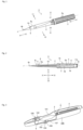
- FIG. 1 is a perspective view showing an overall structure of an intraocular lens injector according to an embodiment of the present invention
- FIG. 2 is a side sectional view showing the overall structure of the intraocular lens injector according to an embodiment of the present invention.
- An intraocular lens injector 1 shown in the figure is provided as a disposable product, and is used when injecting the intraocular lens into the eye.
- the intraocular lens injector 1 is of a preload type in which an intraocular lens is preset.
- the intraocular lens is preset on the lens setting portion described later in the stage of shipping the intraocular lens injector 1 from a factory.
- X1 direction is set as a tip end side (front side)
- X2 direction is set as a rear end side (rear side)
- Y1 direction is set as a right side (right side)
- Y2 direction is set as a left side (left side)
- Z1 direction is set as an upper side (upper side)
- Z2 direction is set as a lower side (lower side).
- the X1 direction and the X2 direction correspond to a direction of a central axis of the intraocular lens injector 1 (hereinafter also referred to simply as a "central axis direction")
- the Y1 direction and the Y2 direction correspond to a width direction (left-right direction) of the intraocular lens injector 1
- the Z1 direction and the Z2 direction correspond to a height direction (vertical direction) of the intraocular lens injector 1.
- a plane parallel to the X1 direction, the X2 direction, the Y1 direction and the Y2 direction is set as a horizontal plane
- a plane perpendicular to the horizontal plane is set as a vertical plane.
- Reference symbol J in the figure indicates the central axis of the intraocular lens injector 1.
- the intraocular lens injector 1 is provided to a user in a state of being housed in a case 100.
- the case 100 is made of resin.
- the case 100 is structured to open upward so that the intraocular lens injector 1 can be attached and detached.
- the case 100 is formed with an opening / closing cover 101 for partially closing an upper part of the case 100 and an injection cover 102 for opening / closing together with the opening / closing cover 101.
- the case 100 has a space capable of housing the intraocular lens injector 1, in which the intraocular lens injector 1 is housed.
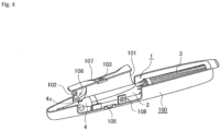
- the opening / closing cover 101 is in a closed state ( FIG. 3 ), and when the intraocular lens injector 1 is taken out from the case 100, the opening / closing cover 101 is in an open state ( FIG. 4 ).
- the opening / closing cover 101 is in a closed state, the intraocular lens injector 1 housed in the case 100 is pressed from above by the opening / closing cover 101.
- the opening / closing cover 101 is in an open state, the upper part of the case 100 is opened.
- An opening / closing operation of the opening / closing cover 101 is performed by a manufacturer or the user of the intraocular lens injector 1.
- the opening / closing cover 101 includes a hooking portion 103.
- the hooking portion 103 is a portion for hooking a user's finger when opening / closing the opening / closing cover 101.
- a slit 104 is formed in the opening / closing cover 101.
- the slit 104 is formed in the vicinity of the hooking portion 103.
- a protrusion 105 is formed in the case 100 as shown in FIG. 4 . The protrusion 105 is engaged with the slit 104 when the opening / closing cover 101 is closed, thereby holding the opening / closing cover 101 in a closed state.
- the injection lid 102 is for injecting a viscoelastic substance.
- a small hole is formed in the injection lid 102, and a part of the injection lid 102 is formed in a funnel shape around this hole.
- the injection lid 102 is partially connected to the opening / closing cover 101 so as to move together with the opening / closing cover 101.
- the case 100 is marked with numbers 106, 107, and 108. Numbers attached to each of the marks 106, 107, and 108 indicate procedures of work to be performed by the user when taking out the intraocular lens injector 1 from the case 100. Further, arrows attached to the marks 107 and 108 indicate directions of work to be performed by the user. Specifically, the mark 106 with the number "1" attached thereto, indicates that the operation of injecting the viscoelastic substance through the injection lid 102 should be performed.
- the mark 107 with the numeral "2" attached thereto indicates that the operation of opening the opening / closing cover 101 in the direction of the arrow should be performed
- the mark 108 with the numeral "3" attached thereto indicates that the operation of taking out the intraocular lens injector 1 in the direction of the arrow should be performed.
- the intraocular lens injector 1 roughly includes an injector main body 2, an operation part 3, an injection tube 4, and a pushing member 5. Each part of the intraocular lens injector 1 is made of resin.
- the injector main body 2 is formed in a tubular shape as a whole.
- a hollow portion that allows the movement of the pushing member 5 in the X1 direction and the X2 direction is formed inside of the injector main body 2.
- a lens setting portion 6 is provided at a tip end part of the injector main body 2.
- the lens setting portion 6 is formed so as to protrude forward from an outer circumferential wall on a lower side of the injector main body 2.
- the intraocular lens 7 is set on the lens setting portion 6 (see FIG. 5 ).
- a central axis J of the intraocular lens injector 1 coincides with each central axis of the injector main body 2, the operation part 3, and the injection tube 4.
- one-piece type intraocular lens 7 made of a soft material such as silicone elastomer or soft acrylic is to be handled.
- the intraocular lens 7 has an optical portion 8 that performs an optical function and a pair (two) support portions 9a, 9b extending outwardly from the outer peripheral edge of the optical portion 8 in an arc shape.
- the optical portion 8 is formed in a circular shape in plan view.
- Each of the pair of support portions 9a, 9b is formed in an elongated arm shape.
- the structure of the lens setting portion 6 will be described in detail with reference to FIG. 5 .
- a guide slope 11 is formed on an upper surface of the lens setting portion 6.
- the guide slope 11 constitutes a guide mechanism for guiding the movement of the pushing member 5 when the pushing member 5 moves in the central axis direction of the injector main body 2.
- the guide slope 11 is formed on a moving path of the pushing member 5 in a state in which a part of the lens setting portion 6 is protruded (raised) upward.
- the guide slope 11 has an inclined portion 11a inclined with respect to a horizontal plane, a top portion 11b not inclined, and a step portion 11c perpendicular to the horizontal plane.
- the inclined portion 11a is inclined in a state in which the inclined portion 11a gradually becomes higher from the back of the lens setting portion 6 toward the front.
- the inclined portion 11a is inclined obliquely upward from the upstream side to the downstream side in the moving direction of the pushing member 5.
- the top portion 11b is formed to extend horizontally from an uppermost portion of the inclined portion 11a.
- the step portion 11c is formed in a state of falling vertically from the tip end of the top portion 11b.
- a pair of right and left recessed grooves are formed in the lens setting portion 6.
- the pair of recessed grooves are formed on the left and right side walls defining the lens setting portion 6 of the injector main body 2 so as to face each other.
- the intraocular lens 7 is set on the lens setting portion 6 having the abovementioned structure, in a state in which one of the support portions 9a is disposed in front of the lens setting portion 6 and the other support portion 9b is disposed behind the lens setting portion 6. Further, the intraocular lens 7 is approximately horizontally set (placed) on the lens setting portion 6 in a state in which a rear edge of the optical portion 8 faces the step portion 11c of the guide slope 11. In FIG. 2 , the notation of the intraocular lens 7 is omitted.
- the operation portion 3 is coaxially connected to the rear end part of the injector main body 2. In this connected state, the operation portion 3 is supported so as to be rotatable around the central axis of the injector main body 2.
- the operation portion 3 is formed into a tubular shape.
- a plurality of protrusions 3a are formed on the outer peripheral surface of the operation portion 3. Each protrusion 3a is formed in parallel to a longitudinal direction of the operation portion 3.
- the operation portion 3 is a portion rotated by a user such as an operator when the intraocular lens 7 is pushed out using the pushing member 5.
- an initial state which is a state of the intraocular lens injector 1.
- a first screw portion 3b is formed on the inner peripheral surface of the operation portion 3.
- the first screw portion 3b constitutes a female screw.
- the first screw portion 3b is formed substantially throughout the central axis direction of the operation portion 3.
- An abutting portion 3c is formed at a rear end part of the operation portion 3.
- the abutting portion 3c is formed by bending inward so as to narrow an opening diameter of the rear end part of the operation portion 3.
- the abutting portion 3c is a portion where the rear end part of a plunger portion 17 abuts so that the plunger portion 17 does not protrude rearward from the rear end part of the operation portion 3.
- An injection tube 4 functions to guide the intraocular lens 7 set on the lens setting portion 6 into an eye in a state that the intraocular lens 7 is folded into a small size when the intraocular lens 7 is injected into the eye.
- the injection tube 4 integrally has a hollow injection tube main body 4a and a narrow tubular nozzle portion 4b.
- the injection tube 4 is attached to a tip end part of the injector main body 2.
- the lens setting portion 6 of the injector main body 2 is housed in the injection tube main body 4a of the injection tube 4.
- the space inside of the injection tube main body 4a is gradually narrowed toward the nozzle portion 4b, for small folding of the intraocular lens 7 pushed out from the lens setting portion 6 to the injection tube 4.
- the intraocular lens 7 is finally rounded and folded so as to embrace the pair of support portions 9a and 9b with the optical portion 8.
- the nozzle portion 4b is formed at the tip end part of the injection tube 4.
- the tip end part of the nozzle portion 4b opens with an oblique incision. Therefore, the opening of the nozzle portion 4b faces obliquely downward.
- the tip end part of the nozzle portion 4b is a portion to be inserted into an incisional wound of the eyeball when the intraocular lens 7 is injected into the eye using the intraocular lens injector 1.
- An injection portion 4c is formed on an upper wall of the injection tube main body 4a, and a through hole 4d is formed on a lower wall of the injection tube main body 4a.
- the injection portion 4c is a portion for injecting a viscoelastic substance (for example, sodium hyaluronate etc.).
- the through hole 4d is a portion into which a pin (not shown) provided vertically erect on the bottom of the abovementioned case 100 is inserted. Such a pin is disposed to protrude through the through hole 4d in the vicinity of a base end portion of the support portion 9b, when the intraocular lens injector 1 incorporating the intraocular lens 7 therein, is housed in the case 100. Thereby, in a state in which the intraocular lens injector 1 is housed in the case 100, the movement of the intraocular lens 7 is suppressed so that the position of the intraocular lens 7 does not largely deviate in the lens setting portion 6.
- the pushing member 5 is provided movably in the central axis direction of the injector main body 2.
- the pushing member 5 functions to push out the intraocular lens 7 form the lens setting portion 6 by moving in the central axis direction (X1 direction) of the injector main body 2. At this time, the pushing member 5 moves in the hollow portion formed by the injector main body 2, the operation portion 3, and the injection tube 4.
- the pushing member 5 has the plunger portion 17 and a rod portion 18.
- the plunger portion 17 and the rod portion 18 may constitute the pushing member 5 in a unitary structure, or the plunger portion 17 and the rod portion 18 may have separate structures and they may be mutually assembled to constitute the pushing member 5.
- the plunger portion 17 is disposed relatively rearwardly, and the rod portion 18 is disposed relatively forward in the direction of the central axis of the intraocular lens injector 1. Therefore, the tip end part of the pushing member 5 corresponds to the tip end part of the rod portion 18.
- the plunger portion 17 is formed into a rod shape. In the initial state before use, the plunger portion 17 is disposed in a state of being inserted into the operation portion 3 so as not to protrude from the rear end part of the operation portion 3. A second screw portion 17a is formed at the rear end part of the plunger portion 17. The second screw portion 17a constitutes a male screw. The second screw portion 17a is engaged with the first screw portion 3b inside of the operation portion 3.
- the operation portion 3 is operated so as to rotate around the central axis of the injector main body 2, thereby moving the entire pushing member 5 in a forward direction.
- a movement start position of the plunger portion 17 at that time is uniquely determined by abutting the rear end part of the plunger portion 17 against the abutting portion 3c of the operation portion 3.
- the pushing member 5 moves in the central axis direction of the injector main body 2, and in this state, the rod portion 18 functions to release the intraocular lens 7 from the opening of the nozzle portion 4b of the injection tube 4, by pushing out the intraocular lens 7 forward, which is set on the lens setting portion 6 is pushed out.
- the rod portion 18 is formed into a rod shape thinner than the plunger portion 17.
- the rod portion 18 is configured to be elastically deformable so as to have moderate flexibility.
- a first contact portion 18a and a second contact portion 18b are formed at the tip end part of the rod portion 18. When the intraocular lens 7 is pushed out by the rod portion 18, the first contact portion 18a comes into contact with the support portion 9b and the second contact portion 18b comes into contact with the optical portion 8.
- the upper end portion of the second contact portion 18b protrudes like a canopy so as to grip the edge of the optical portion 8.
- the lower surface of the tip end side of the rod portion 18 is an inclined surface 18c gently inclined rearward from the second contact portion 18b.
- the pushing member 5 is attached to the operation portion 3. Specifically, the tip end opening part of the operation portion 3 is engaged with the rear end part of the plunger portion 17 of the pushing member 5 so as to cover this opening part, so that the operation portion 3 is rotated. Thereby, the first screw portion 3b formed on the inner peripheral surface of the operation portion 3 and the second screw portion 17a provided at the rear end part of the plunger portion 17 are engaged with each other. Therefore, when the operation portion 3 is rotated while restricting the rotation of the pushing member 5, the plunger portion 17 is inserted into the operation portion 3 in accordance with the rotation of the operation portion 3. At this time, the operation portion 3 is rotated until the rear end part of the plunger portion 17 abuts against the abutting portion 3c of the operation portion 3.
- the injector main body 2 is attached to the operation portion 3.
- the rod portion 18 of the pushing member 5 is inserted into the hollow portion of the injector main body 2.
- the tip end parts (18a, 18b) of the rod portion 18 are disposed slightly in front of the lens setting portion 6.
- the separately prepared intraocular lens 7 is horizontally set on the lens setting portion 6 of the injector main body 2.
- the optical portion 8 of the intraocular lens 7 is disposed slightly forward of the step portion 11c of the guide slope 11.
- one support portion 9a is disposed frontward and the other support portion 9b is disposed rearward.
- the tip end side of the support portion 9b is disposed to block the moving direction of the rod portion 18.
- the intraocular lens 7 is set in a no-load state.
- the no-load state refers to a state in which almost no load (pressure) is applied to the intraocular lens, that is, a state in which the intraocular lens maintains its original shape.
- the original shape of the intraocular lens refers to the shape in the stage of finishing manufacturing the intraocular lens.
- the injection tube 4 is attached to the tip end part of the injector main body 2.
- the assembly of the intraocular lens injector 1 incorporating the intraocular lens 7 is completed.
- the structure for connecting the injector main body 2 and the operation portion 3 and the structure for connecting the injector main body 2 and the injection tube 4 for example, the structure described in the specification of Japanese Patent Application No. 2014-55761 and drawings (Japanese Patent Application Laid-open No. 2015-177845 ) may be adopted, or any other connecting structure may be adopted.
- the intraocular lens injector 1 After the assembly of the intraocular lens injector 1 is completed as described above, the intraocular lens injector 1 is housed in the case 100, and the opening / closing cover 101 is closed. At this time, the injection lid 102 of the case 100 is placed over the injection part 4c of the intraocular lens injector 1. In this state, the intraocular lens injector 1 is stored in a sterilized bag or the like together with the case 100.
- the user takes out the intraocular lens injector 1 from a sterilized bag or the like together with the case 100.
- the user injects the viscoelastic substance from the injection lid 102 in accordance with an instruction of the mark 106.
- the viscoelastic substance is injected (supplied) from the injection lid 102 through the injection portion 4c to the intraocular lens 7 set on the lens setting portion 6.
- the user opens the opening/closing cover 101 in accordance with the instruction of the mark 107. Then, it is possible to obtain a state in which the mark 108 hidden by the opening / closing cover 101 is visible. Therefore, the user takes out the intraocular lens injector 1 from the case 100 in accordance with the instruction of the mark 108.
- the pushing member 5 moves forward by the engagement between the first screw portion 3b and the second screw portion 17a. At this time, the plunger portion 17 of the pushing member 5 moves straight in the central axis direction (X1 direction) of the injector main body 2 while engaging with the hollow portion of the injector main body 2. Further, the pushing member 5 moves as shown in FIGS. 6(A) to 6(D) in accordance with the rotation operation of the operation portion 3.
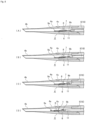
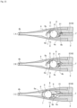
- FIG. 6(A) shows a stage in which the tip end part of the rod portion 18 of the pushing member 5 is advanced to the tip end part of the lens setting portion 6, and FIG. 6(B) shows a stage in which the tip end part of the rod portion 18 is advanced to the injection tube main body 4a of the injection tube 4. Further, FIG. 6(C) shows a stage in which the tip end part of the rod portion 18 is advanced to the nozzle portion 4b of the injection tube 4, and FIG. 7(D) shows a stage in which the tip end part of the rod portion 18 protrudes forward from the nozzle portion 4b of the injection tube 4.
- the tip end part of the rod portion 18 moves forward so as to push out the intraocular lens 7 from the lens setting portion 6.
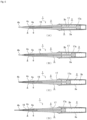
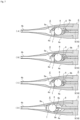
- the tip end part of the rod portion 18 pass the lens setting portion 6 mainly through four stages, by being guided by the guide slope 11. This state is shown in a plane sectional view of FIGS. 7(A) to 7(D) and a side sectional view of FIGS. 8(A) to 8(D) . Each stage will be described hereafter in detail.
- the first stage is the stage in which the tip end part of the rod portion 18 comes into contact with the support portion 9b as shown in FIGS. 7(A) and 8(A) .
- the first contact portion 18a at the tip end of the rod portion 18 comes into contact with the tip end side of the support portion 9b. Further, the tip end side of the support portion 9b is supported in a manner of riding onto the first contact portion 18a.
- the second stage is the stage of pushing the support portion 9b while the tip end part of the rod portion 18 comes into contact with the support portion 9b, as shown in FIGS. 7(B) and 8(B) .
- the tip end part of the rod portion 18 reaches the inclined portion 11a of the guide slope 11, an upward force is applied to the tip end part of the rod portion 18.
- the tip end part of the rod portion 18 is displaced upward due to an elastic deformation of the rod portion 18 itself. Therefore, the tip end part of the rod portion 18 moves forward so as to push the support portion 9b while being displaced upward along the inclined portion 11a of the guide slope 11.
- the support portion 9b is gradually bent. Further, the tip end side of the support portion 9b is gradually raised.
- the pair of support portions 9a and 9b are made of a material which is soft and easily elastically deformed, even if the support portion 9b is pushed in by the tip end part of the rod portion 18, the pushing force is absorbed by deformation of the support portion 9b. Therefore, even if the support portion 9b is pushed in by the tip end part of the rod portion 18, the position of the optical portion 8 hardly changes from an initial state.
- the third stage is the stage in which the tip end part of the rod portion 18 comes into contact with the optical portion 8, as shown in FIGS. 7 (C) and 8 (C) .
- the tip end part of the rod portion 18 comes into contact with the optical portion 8 by reaching the top portion 11b of the guide slope 11 and passing therethrough.
- the second contact portion 18b formed at the tip end part of the rod portion 18 comes into contact with the edge of the optical portion 8.
- the support portion 9b is further bent by the forward movement of the rod portion 18. Specifically, the support portion 9b as a whole is bent toward the optical portion 8 so as to form a substantially U-shape.
- the tip end side of the support portion 9b is properly raised before the tip end part of the rod portion 18 comes into contact with the optical portion 8. Therefore, the tip end part of the support portion 9b is less likely to catch on the edge of the optical portion 8, and in this situation, the tip end part of the support portion 9b rides onto the surface of the optical portion 8.
- the fourth stage is the stage in which the tip end part of the rod portion 18 pushes the entire intraocular lens 7 while coming into contact with the support portion 9b and the optical portion 8, as shown in FIGS. 7(D) and 8(D) .
- a downward force is exerted on the tip end part of the rod portion 18 by a reaction force due to the elastic deformation of the rod portion 18 itself, and therefore the inclined surface 18c of the rod portion 18 is pushed against the edge portion (the upper end of the step portion 11c) of the lower guide slope 11. Therefore, the tip end part of the rod portion 18 is gradually displaced downward in accordance with the inclination of the inclined surface 18c immediately after passing through the step portion 11c of the guide slope 11, and finally returns to an original height position.
- the intraocular lens 7 thus pushed out from the lens setting portion 6, is subsequently pushed by the rod portion 18 and moves forward in the injection tube 4.
- the optical portion 8 of the intraocular lens 7 is rounded from the left and right by the inner wall of the injection tube main body 4a having a tapered shape, and is finally folded so as to embrace the pair of support portions 9a, 9b.
- the support portion 9a is bent in conformity with the shape of the gradually narrowed space in the injection tube 4 (see FIG. 7 (D) ).
- the intraocular lens 7 thus folded is pushed out from the nozzle portion 4b of the injection tube 4 by the rod portion 18. At this time, by pushing out the intraocular lens 7 from the opening of the nozzle portion 4b in a state in which the nozzle portion 4b of the injection tube 4 is inserted into the incisional wound of the eyeball, the intraocular lens 7 can be injected into the eye.
- the tip end part of the rod portion 18 is guided by the guide mechanism so as to be displaced in a direction (vertical direction in this embodiment) intersecting the central axis of the injector main body 2, when the pushing member 5 moves in the central axis direction of the injector main body 2.
- the guide slope 11 in the injector main body 2 by forming the guide slope 11 in the injector main body 2 and displacing the tip end part of the rod portion 18 in the vertical direction along the guide slope 11, it is possible to raise the tip end side of the support portion 9b upward. Therefore, it is possible to create a situation in which the tip end part of the support portion 9b is easy to ride on the surface of the optical portion 8.
- the tip end part of the rod portion 18 pushes the support portion 9b while being displaced upward along the inclined portion 11a of the guide slope 11. Therefore, it is possible to perform the operation of bending the support portion 9b and the operation of raising the support portion 9b in parallel in a series of pushing operations by the pushing member 5.
- FIGS. 1 to 8 the abovementioned embodiment
- the other embodiments are referred to as a second embodiment, a third embodiment and the like, respectively.
- the same reference numerals are given to the same parts as those of the embodiment (the first embodiment) described above.
- the structure of the guide mechanism for guiding the movement of the pushing member 5 is different from that of the abovementioned first embodiment.
- the guide slope 11 is formed on the lens setting portion 6 of the injector body 2, and the guide mechanism is constituted by this guide slope 11.
- guide slopes are respectively provided on the upper side and the lower side of a moving path of the pushing member 5, and the guide mechanism is constituted by these guide slopes.
- the guide mechanism of the second embodiment includes a suppressing portion for suppressing a lateral shake of the tip end part of the pushing member 5.
- FIG. 9 is a sectional view showing an essential part of the intraocular lens injector according to the second embodiment of the present invention.
- FIG. 9 is a view obtained by vertically sectioning the essential part of the intraocular lens injector on the central axis J ( FIG. 1 ), wherein a left direction corresponds to the X1 direction, a right direction corresponds to the X2 direction, an upward direction corresponds to the Z1 direction, and a downward direction corresponds to the Z2 direction in the figure.
- the guide mechanism for guiding the movement of the pushing member 5 is constituted by the lower guide slope 11 and the upper guide slope 12.
- the lower guide slope 11 is constituted by the inclined portion 11a, the top portion 11b and the step portion 11c.
- the upper guide slope 12 is constituted by the inclined portion 12a.
- the lower guide slope 11 is formed on the lens setting portion 6 of the injector main body 2, and the upper guide slope 12 is formed on the inner wall of the injection tube 4.
- the inclined portion 12a of the upper guide slope 12 is disposed on the downstream side of the inclined portion 11a of the lower guide slope 11.
- the lower guide slope 11 displaces the tip end part of the rod portion 18 of the pushing member 5 upward using the inclined portion 11a
- the upper guide slope 12 displaces the tip end part of the rod portion 18 downward using the inclined portion 12a. Therefore, the inclined portion 11a of the lower guide slope 11 is inclined obliquely upward from the upstream side toward the downstream side in the moving direction (X1 direction) of the pushing member 5, and the inclined portion 12a of the upper guide slope 12 is inclined obliquely downward from the upstream side to the downstream side in the moving direction (X1 direction) of the pushing member 5.
- grooves 13, 14 are formed in pairs at upper and lower positions on the lens setting portion 6 of the injector main body 2, and the upper wall portion inside of the insertion tube 4 opposed to the lens setting portion 6.
- the groves 13 and 14 constitute a suppressing portion for suppressing the lateral shake of the tip end part of the pushing member 5 when the pushing member 5 moves in the central axis direction of the injector main body 2.
- the term "lateral shake of the tip end part of the pushing member 5" refers to a situation that the tip end part of the rod portion 18 swings in the left-right direction when the pushing member 5 waiting behind the lens installing portion 6 is moved in the X1 direction by the rotation operation of the operation portion 3.
- the tip end part of the pushing member 5 swings horizontally, the tip end part of the rod portion 18 cannot be stably brought into contact with a target position of the intraocular lens 7.
- the groove 13 is formed on the lower side of the movement path of the rod portion 18, and the groove 14 is formed on the upper side of the movement path of the rod portion 18. Therefore, the groove 13 and the groove 14 are opposed to each other in a vertical direction interposing the movement path of the rod portion 18.
- the lower groove 13 is referred to as a lower groove 13
- the upper groove 14 is referred to as an upper groove 14.
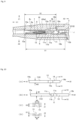
- FIG. 10 is a view for explaining the structure of the lower groove and the upper groove
- (A) is a schematic view when the upper groove is viewed from the position of the central axis of the injector main body
- (B) is a schematic view when the lower groove is viewed from the position of the central axis of the injector main body
- (C) is a view showing a sectional structure of the upper groove at the position V 1 - V 1 of (A)
- (D) is a view showing a sectional structure of the lower groove at the position V 2 - V 2 of (B).
- the lower groove 13 and the upper groove 14 are formed so as to be engaged with the tip end part of the rod portion 18 of the pushing member 5 in order to suppress the lateral shake of the tip end part of the pushing member 5.
- the lower groove 13 is recessed downward and the upper groove 14 is recessed upward.
- a width W1 of the lower groove 13 is set corresponding to a width of the tip end part of the rod portion 18, and a width W2 of the upper groove 14 is also set corresponding to a width dimension of the tip end part of the rod portion 18.
- FIG. 9 shows a state before the operation portion 3 of the intraocular lens injector 1 is rotated, namely, shows an initial state. In this initial state, the tip end part of the rod portion 18 receives a downward force.
- This downward force can be generated, for example, by elastically deforming the rod portion 18 itself so as to press the tip end part of the rod portion 18 downward. This point is the same in the first embodiment as well. Further, in the initial state, the lower side of the tip end part of the rod portion 18 is engaged with the lower groove 13.
- a range S1 for forming the lower groove 13 is a range from a tip end 13a to a rear end 13b of the lower groove 13
- a range S2 for forming the upper groove 14 is a range from a tip end 14a to a rear end 14b of the upper groove 14.
- the lower guide slope 11 is included in the range S1 of the lower groove 13
- the upper guide slope 12 is included in the range S2 of the upper groove 14.
- the lower groove 13 and the upper groove 14 are formed linearly respectively along the central axis direction of the intraocular lens injector 1.
- the lower guide slope 11 is formed in the middle of the lower groove 13, and the upper guide slope 12 is formed in the middle of the upper groove 14.
- the tip end 13a of the lower groove 13 is disposed at substantially the same position as the tip end 14a of the upper groove 14, and the rear end 13b of the lower groove 13 is disposed at a position displaced rearward from the rear end 14b of the upper groove 14. Therefore, the range S1 of the lower groove 13 is wider (longer) than the range S2 of the upper groove 14. Further, in the portion where the lower guide slope 11 is formed, the lower groove 13 is partly interrupted by the protrusion of the lower guide slope 11. The upper groove 14 is continuously formed in the middle of the range S2 without interruption. A depth D1 of the lower groove 13 is substantially uniform throughout the range S1. However, in the vicinity of the tip 13a of the lower groove 13, the depth D1 of the lower groove 13 gradually becomes shallow.
- a depth D2 of the upper groove 14 is deeper on the upstream side than the downstream side of the upper side guide slope 12. Further, in the portion where the upper guide slope 12 is formed, the depth D2 of the upper groove 14 is continuously changed in accordance with the inclination of the inclined portion 12a.
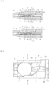
- FIG. 11(A) shows a stage in which the tip end part of the rod portion 18 of the pushing member 5 moves to a position in front of the lower guide slope 11
- FIG. 8(B) shows a stage in which the tip end part of the rod portion 18 moves to the inclined portion 11a of the lower guide slope 11
- FIG. 5(C) shows a stage in which the tip end part of the rod portion 18 is moved to the top portion 11b of the lower guide slope 11.
- FIG. 12(A) shows a stage in which the tip end part of the rod portion 18 moves forward of the lower guide slope 11
- FIG. 8(B) shows a stage in which the tip end part of the rod portion 18 moves forward of the upper guide slope 12.
- the tip end part of the rod portion 18 moves forward while being engaged with the lower groove 13, and during this movement, the first contact portion 18a of the rod portion 18 comes into contact with the support portion 9b of the intraocular lens 7. Thereby, the tip end side of the support portion 9b is supported in a manner of riding onto the first contact portion 18a. Further, the tip end part of the rod portion 18 also engages with the upper groove 14 in the middle of the movement.
- the tip end part of the rod portion 18 moves while displacing upward along the inclined portion 11a of the lower guide slope 11. At this time, the tip end part of the rod portion 18 moves so as to push the support portion 9b while displacing upward by the elastic deformation of the rod portion 18 itself. Thereby, the support portion 9b is gradually bent. Further, the tip end side of the support portion 9b is gradually raised.
- the tip end part of the rod portion 18 reaches the top portion 11b while displacing upward along the inclined portion 11a of the lower guide slope 11, and thereafter moves along the top portion 11b. At that time, the tip end part of the rod portion 18 moves while being engaged with the upper groove 14. Further, the second contact portion 18b of the rod portion 18 comes into contact with the edge of the optical portion 8 in the middle of or immediately after passing through the top portion 11b.
- the tip end part of the rod portion 18 moves while being displaced downward along the inclined portion 12a of the upper guide slope 12.
- the tip end part of the rod portion 18 moves while being engaged with the upper groove 14, and passes through the lower guide slope 11, and thereafter is engaged with the lower groove 13 again, and returns to an original height position.
- the tip end parts (18a, 18b) of the rod portion 18 push the entire intraocular lens 7 while being in contact with the support portion 9b and the optical portion 8. Therefore, the intraocular lens 7 further moves forward from the initial state.
- the guide slope 11 similar to that of the first embodiment is formed, and therefore even if the upper guide slope 12 is not formed, it is possible to displace the tip end part of the rod portion 18 downward by the same principle as in the first embodiment.
- a reaction force due to the elastic deformation of the rod portion 18 becomes weaker, and therefore there is a possibility that the operation of the rod portion 18 becomes unstable when the tip end part of the rod portion 18 rides onto the lower guide slope 11. Accordingly, in order to operate the rod portion 18 more stably, it is preferable to form the upper guide slope 12.
- the upper guide slope 12 When the upper guide slope 12 is formed as in the second embodiment, the upper end of the tip end part of the rod portion 18 approaches or comes into contact with the inclined portion 12a of the upper guide slope 12, immediately after the tip end part of the rod portion 18 passes through the step portion 11c of the lower guide slope 11. Therefore, the tip end part of the rod portion 18 is forcibly displaced downward along the inclined portion 12a of the upper guide slope 12. Accordingly, the displacement operation of the rod portion 18 becomes more stable.
- the tip end part of the rod portion 18 moves while being engaged with both the lower groove 13 and the upper groove 14. At this time, the tip end parts (18a, 18b) of the rod portion 18 further push the entire intraocular lens 7 while coming into contact with the support portion 9b and the optical portion 8.
- the tip end part of the rod portion 18 moves further forward while being engaged with both the lower groove 13 and the upper groove 14.
- the tip end part of the rod portion 18 disengages from the lower groove 13 at the stage of passing through the distal end 13a of the lower groove 13, and disengages from the upper groove 14 at the stage of passing through the tip end 14a of the upper groove 14. Therefore, the tip end part of the rod portion 18 moves while being engaged with both the lower groove 13 and the upper groove 14 except when it passes through the portion of the lower guide slope 11. Further, the tip end part of the rod portion 18 moves while being engaged with the upper groove 14 when it passes through the portion of the lower guide slope 11. Accordingly, the end portion of the rod portion 18 is continuously suppressed from the lateral shake due to the engagement with at least one of the grooves 13, 14 until the end of the passage through the ranges S1, S2 of the grooves 13, 14.
- the guide mechanism for guiding the movement of the pushing member 5 is constituted by the lower guide slope 11 and the upper guide slope 12. Therefore, it is possible to more stably perform the operation of vertically displacing the tip end part of the rod portion 18 of the pushing member 5.
- the lateral shake of the tip end part of the rod portion 18 is suppressed by the upper and lower grooves 13 and 14 when the tip end part of the rod portion 18 of the pushing member 5 is displaced in the vertical direction. Therefore, the tip end part of the rod portion 18 can be advanced straight. Accordingly, it is possible to bring the tip end part of the rod portion 18 into stable contact with the target position of the intraocular lens 7.
- the lower groove 13 and the upper groove 14 are formed in order to suppress the lateral shake of the tip end part of the pushing member 5.
- a structure other than the groove may be adopted as long as it exhibits the same function.
- the one-piece type intraocular lens 7 is made of a very soft material, and therefore when the support portion 9b is pushed in by the rod portion 18, there is a possibility that the shape of the support portion 9b is largely collapsed because the support portion 9b does not bend into a shape as expected by design. When such a phenomenon occurs, even if the support portion 9b is pushed by the rod portion 18, the tip end part of the support portion 9b can not be placed on the surface of the optical portion 8 as specified.
- the intraocular lens injector 1 suitable for handling the one-piece type intraocular lens 7 in which the entire intraocular lens 7 is made of a soft material.
- the intraocular lens injector 1 according to the third embodiment of the present invention can also be applied to a case of handling intraocular lenses other than the one-piece type.
- the structure of the lens setting portion 6 of the injector main body 2 is different, compared to the first embodiment described above.
- the structure of the lens setting portion 6 will be described hereafter in detail with reference to FIG. 13 .
- a guide groove 21 is formed in the lens setting portion 6.
- the guide groove 21 constitutes a guide mechanism for guiding the movement of the tip end part of the pushing member 5, when the pushing member 5 moves in the central axis direction of the injector main body 2.
- the guide groove 21 is formed in such a manner that the upper surface of the lens setting portion 6 is recessed in a concave shape in front of a region where the optical portion 8 is disposed in the lens setting portion 6.
- the guide groove 21 is curved with respect to the central axis J when the lens setting portion 6 is viewed from above.
- the upstream side (the right side in the figure) of the guide groove 21 curves in the right direction Y1 so as to be away from the position of the central axis J
- the downstream side (the left side in the figure) of the guide groove 21 is curved in the left direction Y2 so as to approach the position of the central axis J.
- the tip end part of the rod portion 18 is engaged with the guide groove 21.
- the tip end part of the rod portion 18 is configured to move along the guide groove 21 while being engaged with the guide groove 21. Further, when the tip end part of the rod portion 18 moves along the guide groove 21, a starting end portion 21a of the guide groove 21 which is a starting side of the movement is located on the central axis J in the left-right direction, and an end point 21b of the guide groove 21 on the opposite side is also located on the central axis J in the left-right direction.
- the tip end part of the support portion 9b is disposed so as to block a movement path of the rod portion 18 moving along the guide groove 21, when the intraocular lens 7 is set on the lens setting portion 6. Further, the tip end part of the support portion 9b is disposed at an middle point 21c in a longitudinal direction of the guide groove 21. In the middle point 21c of the guide groove 21, a curved direction of the guide groove 21 is switched from the right direction Y1 to the left direction Y2, and the tip end part of the support portion 9b is disposed in this portion.
- the tip end part of the rod portion 18 moves as follows by being guided by the guide groove 21.
- the tip end part of the rod portion 18 starts to move from a starting point 21a of the guide groove 21 located on the central axis J (see FIG. 13 ).
- the tip end part of the rod portion 18 moves from the starting point 21a to the middle point 21c of the guide groove 21 (see FIG. 13 ) along the guide groove 21.
- the tip end part of the rod portion 18 moves (advances) while displacing to the right direction Y1, due to the elastic deformation of the rod portion 18 itself.
- the tip end part of the rod portion 18 comes into contact with the tip end part of the support portion 9b at a position where it reaches the middle point 21c of the guide groove 21 (in other words, at a position deviated from the position of the central axis J in the right direction Y1).
- the first contact portion 18a formed at the tip end part of the rod portion 18 comes into contact with the tip end part of the support portion 9b. Thereby, the tip end part of the support portion 9b is supported in a manner of riding onto the first contact portion 18a.
- the tip end part of the rod portion 18 pushes the support portion 9b while moving along the guide groove 21.
- the support portion 9b is gradually bent by the forward movement of the rod portion 18. Further, the tip end part of the rod portion 18 moves (forwards) while displacing in the left direction Y2 in accordance with the curve of the guide groove 21.
- the tip end part of the rod portion 18 comes into contact with the optical portion 8 when it reaches the end point 21b (see FIG. 13 ) of the guide groove 21 located on the central axis J.
- the tip end part of the rod portion 18 comes into contact with the optical portion 8 at the position of the central axis J passing through substantially the center of the optical portion 8.
- the second contact portion 18b formed at the tip end part of the rod portion 18 comes into contact with the edge of the optical portion 8.
- the support portion 9b is further bent by the forward movement of the rod portion 18 along the guide groove 21. Specifically, the support portion 9b as a whole is bent toward the optical portion 8 so as to form a substantially U-shape.
- the tip end part of the rod portion 18 pushes the entire intraocular lens 7 while being in contact with the support portion 9b and the optical portion 8. In this stage, the tip end part of the rod portion 18 has passed through the guide groove 21. Therefore, the tip end part of the rod portion 18 moves straight along the central axis J.
- the description is omitted since it is the same as the first embodiment described above.
- the tip end part of the rod portion 18 is guided by the guide mechanism so as to be displaced in a direction crossing the central axis of the injector main body 2 (in the left-right direction in this embodiment).
- the position where the tip end part of the rod portion 18 comes into contact with the support portion 9b is positioned closer to the middle point in the longitudinal direction of the support portion 9b, as compared with the third embodiment.
- a risk that the tip end side of the support portion 9b is bent in a direction different from an expected direction by design is increased when the support portion 9b is pushed in by the tip end part of the rod portion 18.
- an expected direction by design typically the opposite direction
- the tip end part of the rod portion 18 is brought into contact with the tip end part of the support portion 9b at a position deviated in the right direction Y1 from the position of the central axis J, and thereafter the tip end part of the rod portion 18 is displaced in the left direction Y2 and is brought into contact with the optical portion 8 at the position of the central axis J. Therefore, the tip end side of the support portion 9b can be bent in the shape as expected by design when the support portion 9b is pushed in by the tip end part of the rod portion 18. Accordingly, the support portion 9b can be bent into a shape as expected. As a result, it is possible to reliably place the tip end part of the support portion 9b on the surface of the optical portion 8.
- the guide groove 21 in the injector main body 2 by forming the guide groove 21 in the injector main body 2 and displacing the tip end part of the rod portion 18 in the left-right direction along the guide groove 21, it is possible to suppress the shape collapse of the support portion 9b. Thereby, it is possible to bend the tip end side of the support portion 9b into a shape as expected and place the tip end part of the support portion 9b on the surface of the optical portion 8.
- the structure of the injector main body 2 and the injection tube 4 are different, as compared to the abovementioned first embodiment.
- a comparative embodiment of the present invention will be described, and thereafter the fourth embodiment of the present invention will be described.
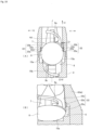
- FIG. 16 shows an internal structure of a joint portion between the injector main body and an injection tube as an essential part of the intraocular lens injector according to a comparative embodiment of the present invention
- (A) is a view of the internal structure of the joint portion viewed from above
- (B) is a perspective view of the internal structure of the joint portion viewed from backside.
- Edge portions 15a, 15b for positioning the intraocular lens 7 placed thereon are formed in the lens setting portion 6 of the injector main body 2.
- the edge portion 15a is formed in a shape conforming to an outer shape of the optical portion 8
- the edge portion 15b is formed in a shape conforming to an outer shape of the support portion 9b.
- a step is provided on each of the edge portions 15a and 15b, and positioning of the intraocular lens 7 can be performed by using this step difference. Namely, in the lens setting portion 6, the optical portion 8 is disposed along the edge portion 15a, and the support portion 9b is disposed along the edge portion 15b, to thereby determine a setting position (hereinafter referred to as "an initial position") of the intraocular lens 7 in an initial state.
- a position of the optical portion 8 at the time of setting the intraocular lens 7 at the initial position is a position where the optical portion 8 starts moving when the intraocular lens 7 is pushed out by the pushing member 5. Therefore, the movement start position of the optical portion 8 in the lens setting portion 6 is set using the edge portion 15a.
- a pair of right and left side wall guides 22, 22 are formed from the lens setting portion 6 to the inside of the injection tube 4 in the central axis direction of the intraocular lens injector 1.
- the pair of side wall guides 22 have guide surfaces 22a and 22b respectively that regulate the position in the right and left direction of the optical portion 8 by bringing the optical portion 8 close to or in contact with the left and right edges of the optical portion 8.
- One guide surface 22a is formed in the lens setting portion 6 and the other guide surface 22b is formed inside of the injection tube 4.
- one guide surface 22a is referred to as a first guide surface 22a
- the other guide surface 22b is referred to as a second guide surface 22b.
- the first guide surface 22a is formed on the lens setting portion 6 so as to be smoothly connected to the edge portion 15a.
- the first guide surface 22a is formed straight along the central axis J of the intraocular lens injector 1.
- the second guide surface 22b is formed on the side wall portion of the injection tube 4 so as to smoothly connect to the first guide surface 22a.
- the second guide surface 22b has an inclination with respect to the central axis J of the intraocular lens injector 1.
- the second guide surface 22b is gradually inclined inward (toward the central axis J of the intraocular lens injector 1) from a joint portion 22c between the first guide surface 22a and the second guide surface 22b.
- the distance is equal to or slightly larger than an outer diameter of the optical portion 8.
- the diameter is gradually decreased from the joint portion 22c with the first guide surface 22a toward the nozzle portion 4b ( FIG. 1 ) of the injection tube 4.
- the intraocular lens 7 set on the lens setting portion 6 when the intraocular lens 7 set on the lens setting portion 6, is pushed out by the rod portion 18 of the pushing member 5, the intraocular lens 7 starts moving from the initial position.
- the optical portion 8 moves forward (in the X1 direction) while being guided by the left and right first guide surfaces 22a.
- the left and right edges of the optical portion 8 reach the joint portion 22c between the first guide surface 22a and the second guide surface 22b.
- the first guide surface 22a and the second guide surface 22b are smoothly connected. Therefore, the optical portion 8 moves forward without being caught by the joint portion 22c.
- the second guide surface 22b is slightly outwardly disposed as compared with the first guide surface 22a so that the optical portion 8 is not caught by the joint portion 22c.
- FIG. 17 in order to easily understand how much the intraocular lens 7 has moved from the initial position shown in FIG. 16 , the shape of the rear support portion 9b is shown in the same manner as in FIG. 16 . However, actually the support portion 9b is pushed by the rod portion 18 and set in a bent state.
- the optical portion 8 moves further forward while being guided by the left and right second guide surfaces 22b.
- the distance between the left and right second guide surfaces 22b is gradually decreased toward the front, and accordingly, the space inside of the injection tube 4 is also gradually narrowed. Therefore, when the intraocular lens 7 is pushed out by the rod portion 18, the optical portion 8 is gradually bent while being guided by the left and right second guide surfaces 22b, and ultimately it is rounded small and folded.
- the first guide surface 22a and the second guide surface 22b of each side wall guide 22 are smoothly connected. Therefore, the optical portion 8 of the intraocular lens 7 moves along the first guide surface 22a and the second guide surface 22b without stopping at the joint portion 22c. In such a case, depending on the physical characteristics of the intraocular lens 7, there is a possibility that the following troubles occurs.
- the pair of support portions 9a, 9b have appropriate flexural rigidity to support the optical portion 8 in the eye. Therefore, depending on the intensity of the flexural rigidity of each of the support portions 9a, 9b, there is a possibility that the optical portion 8 starts to move in a state in which the bending deformation of the support portion 9b is insufficient, namely, at a timing earlier than expected when the support portion 9b is pushed in by the first contact portion 18a of the rod portion 18. In such a case, when the first guide surface 22a and the second guide surface 22b are smoothly connected as in the comparative embodiment, there is a possibility that the optical portion 8 is pushed forward with no riding of the tip end part of the support portion 9b onto the surface of the optical portion 8.
- the tip end part of the support portion 9b is easily caught on the edge of the optical portion 8.
- a pair of right and left recessed grooves for limiting a vertical displacement amount of the optical portion 8 is formed in the lens setting portion 6. Then in the initial state, the left and right outer peripheral parts of the optical portion 8 are disposed in the corresponding recessed grooves, thereby restricting the movement of the optical portion 8 in the vertical direction.
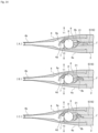
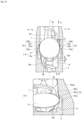
- FIG. 18 shows the internal structure of the joint portion between the injector main body and the injection tube as the essential part of the intraocular lens injector according to a fourth embodiment of the present invention, and (A) is a view of the internal structure of the joint portion viewed from above, and (B) is a perspective view of the internal structure of the joint portion viewed from the backside.
- the fourth embodiment is intended to solve the problem which may occur in the above comparative embodiment.
- the difference between the fourth embodiment and the comparative embodiment lies in the structure of the pair of side wall guides 22, 22.
- the first guide surface 22a and the second guide surface 22b of each side wall guide 22 are smoothly connected.
- the first guide surface 22a and the second guide surface 22b are not connected smoothly but the protrusion 22d is formed on the joint portion 22c.
- the protrusion 22d temporarily stops the optical portion 8 of the intraocular lens 7 pushed out by the pushing member 5.
- the protrusion 22d is formed at the joint portion 22c so that the second guide surface 22b protrudes inward from the first guide surface 22a (a side close to the central axis J of the intraocular lens injector 1) by a predetermined dimension Ly.
- the distance between the left and right side wall guides 22, 22 is shorter than the diameter of the optical portion 8 due to the protrusion of the protrusion 22d. Therefore, when the intraocular lens 7 set at the initial position of the lens setting portion 6 is pushed out by the pushing member 5, the left and right edges of the optical portion 8 are caught on the corresponding protrusion 22d.
- the protruding dimension Ly of the protrusion 22d corresponds to the amount of positional deviation in the left-right direction between the first guide surface 22a and the second guide surface 22b at the joint portion 22c, and it is preferably 0.1 mm or more and 0.5 mm or less. Since the protrusion 22d exists on both the left and right sides, for example, when the protruding dimension of the protrusion 22d is set to 0.2 mm, the distance between the left and right side wall guides 22 and 22 is shortened to 0.4 mm in total (0.2 mm on each side).
- the protrusion 22d is disposed so that when the optical portion 8 is disposed at the movement start position, it does not contact the optical portion 8, and when the optical portion 8 moves from the movement start position by a predetermined amount M (see FIG. 19 (A) ), it comes into contact with the optical portion 8.
- the predetermined amount M is preferably 0.5 mm or more and 1.0 mm or less, and more preferably 0.6 mm or more and 0.8 mm or less.
- the predetermined amount M is set to be shorter than a moving distance of the optical portion 8 until the outer peripheral part of the optical portion 8 is disengaged from the left and right recessed grooves. Thereby, the optical portion 8 can be brought into contact with the protrusion 22d before the outer peripheral part of the optical portion 8 is disengaged from the recessed groove.
- the distance between the left and right side wall guides 22, 22 is as follows. First, in the portion where the first guide surface 22a is formed, the above distance is the same as or slightly larger than the outer diameter of the optical portion 8 in the same manner as in the abovementioned comparative embodiment. In contrast, in the portion where the second guide surface 22b is formed, the above distance is gradually decreased from the protrusion 22d formed in the connecting portion 22c toward the nozzle portion 4b of the injection tube 4.
- the intraocular lens 7 set on the lens setting portion 6 when the intraocular lens 7 set on the lens setting portion 6 is pushed forward by the rod portion 18 of the pushing member 5, the intraocular lens 7 starts moving from its initial position.
- the optical portion 8 moves forward (in the X1 direction) while being guided by the left and right first guide surfaces 22a.
- the left and right edges of the optical portion 8 reach the joint portion 22c between the first guide surface 22a and the second guide surface 22b.
- the protrusion 22d is formed on this joint portion 22c. Therefore, as shown in FIGS. 19(A) and 19(B) , the left and right edges of the optical portion 8 come into contact with and hooked on the corresponding protrusion 22d respectively, and the optical portion 8 is temporarily stopped by this hooking.
- the support portion 9b can be sufficiently bent at the tip end part of the rod portion 18 while the optical portion 8 is temporarily stopped so that the tip end part of the support portion 9b can be placed on the surface of the optical portion 8. Further, by temporarily stopping the optical portion 8 before the left and right outer peripheral parts of the optical portion 8 are disengaged from the recessed groove, the tip end part of the rod portion 18 can be brought into contact with the edge of the optical portion 8, while limiting the amount of displacement in the vertical direction (in particular, upward direction) of the optical section 8 by the recessed groove. Therefore, the tip end part of the support portion 9b can be placed on the surface of the optical portion 8 without being hooked on the edge of the optical portion 8.
- the optical portion 8 moves forward while being guided by the left and right second guide surfaces 22b.
- the distance between the left and right second guide surfaces 22b is gradually decreased toward the front, and accordingly, the space inside of the injection tube 4 is also gradually narrowed. Therefore, when the intraocular lens 7 is pushed out by the rod portion 18, the optical portion 8 is gradually bent while being guided by the left and right second guide surfaces 22b, and ultimately it is rounded small and folded. At that time, when the tip end part of the support portion 9b rides on the surface of the optical portion 8, the optical portion 8 is likely to bend in a direction to embrace the support portion 9b.
- the optical portion 8 is easily deformed to the side on which the support portion 9b is placed, whereas the optical portion 8 is hardly deformed on the opposite side. Therefore, even when the optical portion 8 starts to move at an earlier timing than expected, the direction in which the optical portion 8 is bent can be determined in one direction (the direction in which the support portion 9b is embraced).
- any structure may be adopted as long as the structure of the protrusion 22d is such that the optical portion 8 can be temporarily stopped.
- the protrusion 22d may be formed so as to form a right angle with respect to the first guide surface 22a as shown in FIG. 20(A) , or the protrusion 22d may be formed so as to form an obtuse angle with respect to the first guide surface 22a as shown in FIG. 20(B) , or the projecting portion 22d may be formed in a round shape from the first guide surface 22a to the second guide surface 22b as shown in FIGS. 20(C) and (D) .
- the protrusion 22d is formed at the joint portion 22c between the first guide surface 22a and the second guide surface 22b.
- the present invention is not limited thereto, and the protrusion 22d may be formed in the middle of the first guide surface 22a or in the middle of the second guide surface 22b for the same purpose as described above.
- the preload type intraocular lens injector 1 is given as an example.
- the present invention is not limited thereto, and the present invention may be applied to an intraocular lens injector of the type in which the user using the intraocular lens injector sets the intraocular lens each time.
- the pushing member 5 is moved forward by the rotating operation of the operation portion 3.
- the present invention is not limited thereto, and it is also acceptable to adopt a structure in which the pushing member is pushed directly using a finger.
- the rod portion 18 of the pushing member 5 is configured to be elastically deformable, and when the pushing member 5 is moved forward, the tip end part of the rod portion 18 is displaced in a predetermined direction (vertical direction, left-right direction) by the elastic deformation of the rod portion 18.
- the present invention is not limited thereto, and for example it is also acceptable to adopt a structure in which the plunger portion 17 and the rod portion 18 are connected to each other and the rod portion 18 is rotatably supported by the joint portion between the plunger portion 17 and the rod portion 18.
- a pair of right and left recessed grooves are formed in the lens setting portion 6.
- the other structure may be acceptable.
- the pressing portions may be disposed above the right and left outer peripheral parts of the optical portion 8 interposing an appropriate gap.
- FIGS. 9 to 12 the following structure is adopted for your reference: a pressing portion 16 is formed inside of the injection tube 4 and the vertical displacement amount of the optical portion 8 is limited by the pressing portion 16.
- the abovementioned first embodiment and the second embodiment adopt a structure in which the tip end portion of the rod portion 18 is displaced in the vertical direction
- the third embodiment adopt a structure in which the tip end portion of the rod portion 18 is displaced in the left-right direction.
- the present invention is not limited thereto, and for example it is also acceptable to adopt a structure in which the tip end portion of the rod portion 18 is displaced in both the vertical direction and the left-right direction by appropriately combining the above embodiments. By adopting this structure, it is possible to more surely place the tip end portion of the support portion 9b on the surface of the optical portion 8.
- the guide groove 21 is curved in the right direction Y1 at a part from the starting point 21a to the middle point 21c of the guide groove 21.
- the present invention is not limited thereto, and the starting point 21a of the guide groove 21 may be disposed deviated in the rightward direction Y1 from the central axis J, and a part extending from the starting point 21a to the middle point 21c may be formed straight along the central axis J.
- the tip end part of the rod portion 18 moves straight through a part from the starting point 21a to the middle point 21c of the guide groove 21, and moves through a part from the middle point 21c to the end point 21b of the guide groove 21 while displacing in the left direction Y2.
Landscapes
- Health & Medical Sciences (AREA)
- Ophthalmology & Optometry (AREA)
- Public Health (AREA)
- Life Sciences & Earth Sciences (AREA)
- Veterinary Medicine (AREA)
- Engineering & Computer Science (AREA)
- Biomedical Technology (AREA)
- Heart & Thoracic Surgery (AREA)
- Vascular Medicine (AREA)
- General Health & Medical Sciences (AREA)
- Animal Behavior & Ethology (AREA)
- Oral & Maxillofacial Surgery (AREA)
- Cardiology (AREA)
- Transplantation (AREA)
- Nuclear Medicine, Radiotherapy & Molecular Imaging (AREA)
- Surgery (AREA)
- Prostheses (AREA)
Description
- The present invention relates to an intraocular lens injector used for injecting an intraocular lens into an eye.
- As one of a cataract surgery, it is widely practiced to extract a white cloudy lens by ultrasonic emulsification and suction and then inject the intraocular lens into the eye. Further, in recent years, in order to realize minimally invasive cataract surgery with less burden on an eye, a one-piece type intraocular lens made of a soft material such as silicone elastomer or soft acrylic is injected into the eye in a small folded state. The one-piece type intraocular lens has an optical portion that performs a lens function and a pair of support portions that extend from the optical portion, and an entire intraocular lens is made of a flexible material.
- Further, as an intraocular lens injector for handling the one-piece type intraocular lens, there is an injector having a function of folding an intraocular lens so as to embrace a pair of support portions with an optical portion in order to improve operability for a surgeon to inject the intraocular lens as much as possible (for example, see patent document 1).
- In this type of intraocular lens injector, it is necessary to fold the optical portion roundly in a state that tip end parts of the respective support portions are placed on a surface of the optical portion. Further, conventional intraocular lens injectors include the one having a pushing member which pushes out an intraocular lens and which folds the intraocular lens when the intraocular lens is pushed out by the pushing member.
-
EP 2 286 764 A1 -
EP 2 161 004 A1 -
CA 2938660 A1 shows an injector for an intraocular lens in which a lens support part is set to an appropriate position on a lens holder. -
WO 2015/012312 A1 shows an intraocular lens inserting instrument in which a shape of a support is stabilized after insertion. - [Patent Document 1] Japanese Unexamined Patent Publication No.
2011-255029 - However, the conventional intraocular lens injector involves a problem that when the intraocular lens is pushed out by the pushing member, the tip end part of the support portion is caught on an edge of the optical portion or the like, and the tip end part of the support portion is not placed smoothly on the surface of the optical portion.
- A main object of the present invention is to provide an intraocular lens injector capable of surely placing the tip end part of the support portion on the surface of the optical portion when the intraocular lens is folded so as to embrace the support portion with the optical portion.
- The present invention is defined by
claim 1. Preferred embodiments are defined by the dependent claims. Further embodiments, aspects and examples disclosed herein are for exemplary purpose only and do not form part of the invention. - According to the present invention, when folding the intraocular lens so as to embrace the support portions with the optical portion, the tip end part of the support portions can be securely placed on the surface of the optical portion.
-
-
FIG. 1 is a perspective view showing an overall structure of an intraocular lens injector according to an embodiment of the present invention. -
FIG. 2 is a side sectional view showing the overall structure of the intraocular lens injector according to an embodiment of the present invention. -
FIG. 3 is a perspective view showing a state in which the intraocular lens injector of the embodiment of the present invention is housed in a case. -
FIG. 4 is a perspective view showing a state in which the intraocular lens injector of the embodiment of the present invention is taken out from the case. -
FIG. 5(A) is a plan sectional view showing a structure of an essential part of the intraocular lens injector according to an embodiment of the present invention, and (B) is a side sectional view showing the structure of the essential part, and (C) is a partially enlarged view of (B). -
FIGS. 6(A) to 6(D) are views showing time-sequentially a state of a movement of a pushing member in accordance with a rotation operation of the operation portion. -
FIG. 7 is a plan sectional view showing a state in which the intraocular lens is pushed out by the pushing member, in a chronological order. -
FIG. 8 is a side sectional view showing a state in which the intraocular lens is pushed out by the pushing member, in a chronological order. -
FIG. 9 is a sectional view showing an essential part of the intraocular lens injector according to a second embodiment of the present invention. -
FIG. 10 is a view for explaining the structure of a lower groove and an upper groove, and (A) is a schematic view when the upper groove is viewed from a position of a central axis of the injector main body, (B) is a schematic view when the lower groove is viewed from the position of the central axis of the injector main body, (C) is a view showing a sectional structure of the upper groove at a position V 1 -V 1 of (A), and (D) is a view showing the sectional structure of the lower groove at a position V 2 -V 2 of (B). -
FIGS. 11(A) to 11(C) are views (part 1) for explaining an operation of the intraocular lens injector according to the second embodiment of the present invention. -
FIGS. 12(A) and (B) are views (part 2) for explaining the operation of the intraocular lens injector according to the second embodiment of the present invention. -
FIG. 13 is an enlarged plan view of the essential structure of the intraocular lens injector according to a third embodiment of the present invention. -
FIG. 14 is a plan sectional view (part 1) showing time-sequentially a state of pushing out the intraocular lens in the intraocular lens injector, using a pushing member according to the third embodiment of the present invention. -
FIG. 15 is a plan sectional view (part 2) showing time-sequentially the state of pushing out the intraocular lens in the intraocular lens injector using the pushing member according to the third embodiment of the present invention. -
FIG. 16 shows an internal structure of a joint portion between the injector main body and an injection tube as an essential part of the intraocular lens injector according to a comparative embodiment of the present invention, and (A) is a view of the internal structure of the joint portion viewed from above, and (B) is a perspective view of the internal structure of the joint portion viewed from backside. -
FIGS. 17(A) and 17(B) are views showing a state of the movement of the intraocular lens in an intraocular lens injector according to a comparative embodiment of the present invention. -
FIG. 18 shows the internal structure of the joint portion between the injector main body and the injection tube as the essential part of the intraocular lens injector according to a fourth embodiment of the present invention, and (A) is a view of the internal structure of the joint portion viewed from above, and (B) is a perspective view of the internal structure of the joint portion viewed from the backside. -
FIGS. 19(A) and 19(B) are views showing a state of the movement of the intraocular lens in an intraocular lens injector according to a fourth embodiment of the present invention. -
FIGS. 20(A) to (D) are views showing an example of the structure of a protrusion according to a fourth embodiment of the present invention. - Embodiments of the present invention will be described hereafter in detail, with reference to the drawings. In the embodiment of the present invention, explanation will be given in the following order.
- 1. Structure of an intraocular lens injector
- 2. Method for assembling the intraocular lens injector
- 3. How to use the intraocular lens injector
- 4. Effect of the embodiment
- 5. Other embodiment
- 6. Modified example, etc.
-
FIG. 1 is a perspective view showing an overall structure of an intraocular lens injector according to an embodiment of the present invention, andFIG. 2 is a side sectional view showing the overall structure of the intraocular lens injector according to an embodiment of the present invention. - An
intraocular lens injector 1 shown in the figure is provided as a disposable product, and is used when injecting the intraocular lens into the eye. Theintraocular lens injector 1 is of a preload type in which an intraocular lens is preset. In the preload typeintraocular lens injector 1, the intraocular lens is preset on the lens setting portion described later in the stage of shipping theintraocular lens injector 1 from a factory. - In this embodiment, in order to clarify a relative positional relationship and a direction of movement and the like of each part of the
intraocular lens injector 1, X1 direction is set as a tip end side (front side), X2 direction is set as a rear end side (rear side), Y1 direction is set as a right side (right side), Y2 direction is set as a left side (left side), Z1 direction is set as an upper side (upper side), and Z2 direction is set as a lower side (lower side). Among them, the X1 direction and the X2 direction correspond to a direction of a central axis of the intraocular lens injector 1 (hereinafter also referred to simply as a "central axis direction"), and the Y1 direction and the Y2 direction correspond to a width direction (left-right direction) of theintraocular lens injector 1, and the Z1 direction and the Z2 direction correspond to a height direction (vertical direction) of theintraocular lens injector 1. Further, a plane parallel to the X1 direction, the X2 direction, the Y1 direction and the Y2 direction is set as a horizontal plane, and a plane perpendicular to the horizontal plane is set as a vertical plane. Reference symbol J in the figure indicates the central axis of theintraocular lens injector 1. - As shown in
FIG. 3 , for example, theintraocular lens injector 1 is provided to a user in a state of being housed in acase 100. Thecase 100 is made of resin. Thecase 100 is structured to open upward so that theintraocular lens injector 1 can be attached and detached. Thecase 100 is formed with an opening /closing cover 101 for partially closing an upper part of thecase 100 and aninjection cover 102 for opening / closing together with the opening /closing cover 101. - The
case 100 has a space capable of housing theintraocular lens injector 1, in which theintraocular lens injector 1 is housed. When theintraocular lens injector 1 is housed in thecase 100, the opening /closing cover 101 is in a closed state (FIG. 3 ), and when theintraocular lens injector 1 is taken out from thecase 100, the opening /closing cover 101 is in an open state (FIG. 4 ). When the opening /closing cover 101 is in a closed state, theintraocular lens injector 1 housed in thecase 100 is pressed from above by the opening /closing cover 101. When the opening /closing cover 101 is in an open state, the upper part of thecase 100 is opened. An opening / closing operation of the opening /closing cover 101 is performed by a manufacturer or the user of theintraocular lens injector 1. - The opening /
closing cover 101 includes a hookingportion 103. The hookingportion 103 is a portion for hooking a user's finger when opening / closing the opening /closing cover 101. Further, aslit 104 is formed in the opening /closing cover 101. Theslit 104 is formed in the vicinity of the hookingportion 103. In contrast, aprotrusion 105 is formed in thecase 100 as shown inFIG. 4 . Theprotrusion 105 is engaged with theslit 104 when the opening /closing cover 101 is closed, thereby holding the opening /closing cover 101 in a closed state. - The
injection lid 102 is for injecting a viscoelastic substance. A small hole is formed in theinjection lid 102, and a part of theinjection lid 102 is formed in a funnel shape around this hole. Theinjection lid 102 is partially connected to the opening /closing cover 101 so as to move together with the opening /closing cover 101. - Further, the
case 100 is marked withnumbers marks intraocular lens injector 1 from thecase 100. Further, arrows attached to themarks mark 106 with the number "1" attached thereto, indicates that the operation of injecting the viscoelastic substance through theinjection lid 102 should be performed. Further, themark 107 with the numeral "2" attached thereto, indicates that the operation of opening the opening /closing cover 101 in the direction of the arrow should be performed, and themark 108 with the numeral "3" attached thereto, indicates that the operation of taking out theintraocular lens injector 1 in the direction of the arrow should be performed. - As shown in
FIGS. 1 and 2 , theintraocular lens injector 1 roughly includes an injectormain body 2, anoperation part 3, aninjection tube 4, and a pushingmember 5. Each part of theintraocular lens injector 1 is made of resin. - The injector
main body 2 is formed in a tubular shape as a whole. A hollow portion that allows the movement of the pushingmember 5 in the X1 direction and the X2 direction is formed inside of the injectormain body 2. Alens setting portion 6 is provided at a tip end part of the injectormain body 2. Thelens setting portion 6 is formed so as to protrude forward from an outer circumferential wall on a lower side of the injectormain body 2. Theintraocular lens 7 is set on the lens setting portion 6 (seeFIG. 5 ). A central axis J of theintraocular lens injector 1 coincides with each central axis of the injectormain body 2, theoperation part 3, and theinjection tube 4. - In this embodiment, as an example, one-piece
type intraocular lens 7 made of a soft material such as silicone elastomer or soft acrylic is to be handled. Theintraocular lens 7 has anoptical portion 8 that performs an optical function and a pair (two)support portions optical portion 8 in an arc shape. Theoptical portion 8 is formed in a circular shape in plan view. Each of the pair ofsupport portions - Here, the structure of the
lens setting portion 6 will be described in detail with reference toFIG. 5 . - A
guide slope 11 is formed on an upper surface of thelens setting portion 6. Theguide slope 11 constitutes a guide mechanism for guiding the movement of the pushingmember 5 when the pushingmember 5 moves in the central axis direction of the injectormain body 2. Theguide slope 11 is formed on a moving path of the pushingmember 5 in a state in which a part of thelens setting portion 6 is protruded (raised) upward. As shown inFIG. 5(C) , theguide slope 11 has aninclined portion 11a inclined with respect to a horizontal plane, atop portion 11b not inclined, and astep portion 11c perpendicular to the horizontal plane. Theinclined portion 11a is inclined in a state in which theinclined portion 11a gradually becomes higher from the back of thelens setting portion 6 toward the front. In other words, theinclined portion 11a is inclined obliquely upward from the upstream side to the downstream side in the moving direction of the pushingmember 5. Thetop portion 11b is formed to extend horizontally from an uppermost portion of theinclined portion 11a. Thestep portion 11c is formed in a state of falling vertically from the tip end of thetop portion 11b. - Further, in order to limit an amount of a vertical displacement of the
intraocular lens 7 set on thelens setting portion 6, a pair of right and left recessed grooves (not shown) are formed in thelens setting portion 6. The pair of recessed grooves are formed on the left and right side walls defining thelens setting portion 6 of the injectormain body 2 so as to face each other. When theintraocular lens 7 is set on thelens setting portion 6, the pair of recessed grooves are engaged with the left and right outer peripheral parts of theoptical portion 8, thereby restricting the vertical movement of theoptical portion 8. - The
intraocular lens 7 is set on thelens setting portion 6 having the abovementioned structure, in a state in which one of thesupport portions 9a is disposed in front of thelens setting portion 6 and theother support portion 9b is disposed behind thelens setting portion 6. Further, theintraocular lens 7 is approximately horizontally set (placed) on thelens setting portion 6 in a state in which a rear edge of theoptical portion 8 faces thestep portion 11c of theguide slope 11. InFIG. 2 , the notation of theintraocular lens 7 is omitted. - The
operation portion 3 is coaxially connected to the rear end part of the injectormain body 2. In this connected state, theoperation portion 3 is supported so as to be rotatable around the central axis of the injectormain body 2. Theoperation portion 3 is formed into a tubular shape. A plurality ofprotrusions 3a are formed on the outer peripheral surface of theoperation portion 3. Eachprotrusion 3a is formed in parallel to a longitudinal direction of theoperation portion 3. Theoperation portion 3 is a portion rotated by a user such as an operator when theintraocular lens 7 is pushed out using the pushingmember 5. At this time, by forming a plurality ofprotrusions 3a on the outer periphery of theoperation portion 3, the fingers of the user are caught on theprotrusions 3a, and therefore it is easy to rotate theoperation portion 3. In this specification, a state before rotating theoperation portion 3 by a user is referred to as an initial state, which is a state of theintraocular lens injector 1. - As shown in
FIG. 2 , afirst screw portion 3b is formed on the inner peripheral surface of theoperation portion 3. Thefirst screw portion 3b constitutes a female screw. Thefirst screw portion 3b is formed substantially throughout the central axis direction of theoperation portion 3. An abuttingportion 3c is formed at a rear end part of theoperation portion 3. The abuttingportion 3c is formed by bending inward so as to narrow an opening diameter of the rear end part of theoperation portion 3. The abuttingportion 3c is a portion where the rear end part of aplunger portion 17 abuts so that theplunger portion 17 does not protrude rearward from the rear end part of theoperation portion 3. - An
injection tube 4 functions to guide theintraocular lens 7 set on thelens setting portion 6 into an eye in a state that theintraocular lens 7 is folded into a small size when theintraocular lens 7 is injected into the eye. Theinjection tube 4 integrally has a hollow injection tubemain body 4a and a narrowtubular nozzle portion 4b. Theinjection tube 4 is attached to a tip end part of the injectormain body 2. In this attachment state, thelens setting portion 6 of the injectormain body 2 is housed in the injection tubemain body 4a of theinjection tube 4. The space inside of the injection tubemain body 4a is gradually narrowed toward thenozzle portion 4b, for small folding of theintraocular lens 7 pushed out from thelens setting portion 6 to theinjection tube 4. Theintraocular lens 7 is finally rounded and folded so as to embrace the pair ofsupport portions optical portion 8. - The
nozzle portion 4b is formed at the tip end part of theinjection tube 4. The tip end part of thenozzle portion 4b opens with an oblique incision. Therefore, the opening of thenozzle portion 4b faces obliquely downward. The tip end part of thenozzle portion 4b is a portion to be inserted into an incisional wound of the eyeball when theintraocular lens 7 is injected into the eye using theintraocular lens injector 1. - An
injection portion 4c is formed on an upper wall of the injection tubemain body 4a, and a throughhole 4d is formed on a lower wall of the injection tubemain body 4a. Theinjection portion 4c is a portion for injecting a viscoelastic substance (for example, sodium hyaluronate etc.). The throughhole 4d is a portion into which a pin (not shown) provided vertically erect on the bottom of theabovementioned case 100 is inserted. Such a pin is disposed to protrude through the throughhole 4d in the vicinity of a base end portion of thesupport portion 9b, when theintraocular lens injector 1 incorporating theintraocular lens 7 therein, is housed in thecase 100. Thereby, in a state in which theintraocular lens injector 1 is housed in thecase 100, the movement of theintraocular lens 7 is suppressed so that the position of theintraocular lens 7 does not largely deviate in thelens setting portion 6. - The pushing
member 5 is provided movably in the central axis direction of the injectormain body 2. The pushingmember 5 functions to push out theintraocular lens 7 form thelens setting portion 6 by moving in the central axis direction (X1 direction) of the injectormain body 2. At this time, the pushingmember 5 moves in the hollow portion formed by the injectormain body 2, theoperation portion 3, and theinjection tube 4. - The pushing
member 5 has theplunger portion 17 and arod portion 18. Theplunger portion 17 and therod portion 18 may constitute the pushingmember 5 in a unitary structure, or theplunger portion 17 and therod portion 18 may have separate structures and they may be mutually assembled to constitute the pushingmember 5. Theplunger portion 17 is disposed relatively rearwardly, and therod portion 18 is disposed relatively forward in the direction of the central axis of theintraocular lens injector 1. Therefore, the tip end part of the pushingmember 5 corresponds to the tip end part of therod portion 18. - The
plunger portion 17 is formed into a rod shape. In the initial state before use, theplunger portion 17 is disposed in a state of being inserted into theoperation portion 3 so as not to protrude from the rear end part of theoperation portion 3. Asecond screw portion 17a is formed at the rear end part of theplunger portion 17. Thesecond screw portion 17a constitutes a male screw. Thesecond screw portion 17a is engaged with thefirst screw portion 3b inside of theoperation portion 3. When theintraocular lens injector 1 is used, theoperation portion 3 is operated so as to rotate around the central axis of the injectormain body 2, thereby moving the entire pushingmember 5 in a forward direction. A movement start position of theplunger portion 17 at that time is uniquely determined by abutting the rear end part of theplunger portion 17 against the abuttingportion 3c of theoperation portion 3. - The pushing
member 5 moves in the central axis direction of the injectormain body 2, and in this state, therod portion 18 functions to release theintraocular lens 7 from the opening of thenozzle portion 4b of theinjection tube 4, by pushing out theintraocular lens 7 forward, which is set on thelens setting portion 6 is pushed out. Therod portion 18 is formed into a rod shape thinner than theplunger portion 17. Therod portion 18 is configured to be elastically deformable so as to have moderate flexibility. Afirst contact portion 18a and asecond contact portion 18b are formed at the tip end part of therod portion 18. When theintraocular lens 7 is pushed out by therod portion 18, thefirst contact portion 18a comes into contact with thesupport portion 9b and thesecond contact portion 18b comes into contact with theoptical portion 8. The upper end portion of thesecond contact portion 18b protrudes like a canopy so as to grip the edge of theoptical portion 8. The lower surface of the tip end side of therod portion 18 is aninclined surface 18c gently inclined rearward from thesecond contact portion 18b. When the pushingmember 5 is moved forward, theinclined surface 18c is formed to displace the tip end part of therod portion 18 upward along theinclined portion 11a of theguide slope 11 in the middle of the movement, and thereafter displace the tip end part of therod portion 18 downward using the inclination of theinclined surface 18c. - Next, a method for assembling the
intraocular lens injector 1 will be described. - First, after preparing the members (2, 3, 4, 5) constituting the
intraocular lens injector 1, the pushingmember 5 is attached to theoperation portion 3. Specifically, the tip end opening part of theoperation portion 3 is engaged with the rear end part of theplunger portion 17 of the pushingmember 5 so as to cover this opening part, so that theoperation portion 3 is rotated. Thereby, thefirst screw portion 3b formed on the inner peripheral surface of theoperation portion 3 and thesecond screw portion 17a provided at the rear end part of theplunger portion 17 are engaged with each other. Therefore, when theoperation portion 3 is rotated while restricting the rotation of the pushingmember 5, theplunger portion 17 is inserted into theoperation portion 3 in accordance with the rotation of theoperation portion 3. At this time, theoperation portion 3 is rotated until the rear end part of theplunger portion 17 abuts against the abuttingportion 3c of theoperation portion 3. - Next, the injector
main body 2 is attached to theoperation portion 3. At this time, therod portion 18 of the pushingmember 5 is inserted into the hollow portion of the injectormain body 2. Thereby, the tip end parts (18a, 18b) of therod portion 18 are disposed slightly in front of thelens setting portion 6. - Next, the separately prepared
intraocular lens 7 is horizontally set on thelens setting portion 6 of the injectormain body 2. At this time, theoptical portion 8 of theintraocular lens 7 is disposed slightly forward of thestep portion 11c of theguide slope 11. Further, onesupport portion 9a is disposed frontward and theother support portion 9b is disposed rearward. Further, the tip end side of thesupport portion 9b is disposed to block the moving direction of therod portion 18. - In the state in which the
intraocular lens 7 is set on thelens setting portion 6 as described above, theintraocular lens 7 is set in a no-load state. The no-load state refers to a state in which almost no load (pressure) is applied to the intraocular lens, that is, a state in which the intraocular lens maintains its original shape. The original shape of the intraocular lens refers to the shape in the stage of finishing manufacturing the intraocular lens. - Next, the
injection tube 4 is attached to the tip end part of the injectormain body 2. Thus, the assembly of theintraocular lens injector 1 incorporating theintraocular lens 7 is completed. For the structure for connecting the injectormain body 2 and theoperation portion 3 and the structure for connecting the injectormain body 2 and theinjection tube 4, for example, the structure described in the specification of Japanese Patent Application No.2014-55761 2015-177845 - After the assembly of the
intraocular lens injector 1 is completed as described above, theintraocular lens injector 1 is housed in thecase 100, and the opening /closing cover 101 is closed. At this time, theinjection lid 102 of thecase 100 is placed over theinjection part 4c of theintraocular lens injector 1. In this state, theintraocular lens injector 1 is stored in a sterilized bag or the like together with thecase 100. - Next, how to use the
intraocular lens injector 1 will be described. - First, the user takes out the
intraocular lens injector 1 from a sterilized bag or the like together with thecase 100. - Next, the user injects the viscoelastic substance from the
injection lid 102 in accordance with an instruction of themark 106. Thereby, the viscoelastic substance is injected (supplied) from theinjection lid 102 through theinjection portion 4c to theintraocular lens 7 set on thelens setting portion 6. - Next, the user opens the opening/
closing cover 101 in accordance with the instruction of themark 107. Then, it is possible to obtain a state in which themark 108 hidden by the opening /closing cover 101 is visible. Therefore, the user takes out theintraocular lens injector 1 from thecase 100 in accordance with the instruction of themark 108. - Thereafter, the user pushes the
intraocular lens 7 from the tip end part of theinjection tube 4 by rotating theoperation portion 3. The operation of each part of theintraocular lens injector 1 at that time will be described. - First, the operation of the pushing
member 5 will be described when theoperation portion 3 is rotated. - When the
operation portion 3 is rotated in one direction, the pushingmember 5 moves forward by the engagement between thefirst screw portion 3b and thesecond screw portion 17a. At this time, theplunger portion 17 of the pushingmember 5 moves straight in the central axis direction (X1 direction) of the injectormain body 2 while engaging with the hollow portion of the injectormain body 2. Further, the pushingmember 5 moves as shown inFIGS. 6(A) to 6(D) in accordance with the rotation operation of theoperation portion 3. -
FIG. 6(A) shows a stage in which the tip end part of therod portion 18 of the pushingmember 5 is advanced to the tip end part of thelens setting portion 6, andFIG. 6(B) shows a stage in which the tip end part of therod portion 18 is advanced to the injection tubemain body 4a of theinjection tube 4. Further,FIG. 6(C) shows a stage in which the tip end part of therod portion 18 is advanced to thenozzle portion 4b of theinjection tube 4, andFIG. 7(D) shows a stage in which the tip end part of therod portion 18 protrudes forward from thenozzle portion 4b of theinjection tube 4. - When the pushing
member 5 is moved as described above, the tip end part of therod portion 18 moves forward so as to push out theintraocular lens 7 from thelens setting portion 6. At that time, the tip end part of therod portion 18 pass thelens setting portion 6 mainly through four stages, by being guided by theguide slope 11. This state is shown in a plane sectional view ofFIGS. 7(A) to 7(D) and a side sectional view ofFIGS. 8(A) to 8(D) . Each stage will be described hereafter in detail. - The first stage is the stage in which the tip end part of the
rod portion 18 comes into contact with thesupport portion 9b as shown inFIGS. 7(A) and8(A) . At this time, as the tip end part of therod portion 18 advances to thelens setting portion 6, thefirst contact portion 18a at the tip end of therod portion 18 comes into contact with the tip end side of thesupport portion 9b. Further, the tip end side of thesupport portion 9b is supported in a manner of riding onto thefirst contact portion 18a. - The second stage is the stage of pushing the
support portion 9b while the tip end part of therod portion 18 comes into contact with thesupport portion 9b, as shown inFIGS. 7(B) and8(B) . At this time, when the tip end part of therod portion 18 reaches theinclined portion 11a of theguide slope 11, an upward force is applied to the tip end part of therod portion 18. Then, the tip end part of therod portion 18 is displaced upward due to an elastic deformation of therod portion 18 itself. Therefore, the tip end part of therod portion 18 moves forward so as to push thesupport portion 9b while being displaced upward along theinclined portion 11a of theguide slope 11. Thereby, thesupport portion 9b is gradually bent. Further, the tip end side of thesupport portion 9b is gradually raised. - When the pair of
support portions support portion 9b is pushed in by the tip end part of therod portion 18, the pushing force is absorbed by deformation of thesupport portion 9b. Therefore, even if thesupport portion 9b is pushed in by the tip end part of therod portion 18, the position of theoptical portion 8 hardly changes from an initial state. - The third stage is the stage in which the tip end part of the
rod portion 18 comes into contact with theoptical portion 8, as shown inFIGS. 7 (C) and8 (C) . At this time, the tip end part of therod portion 18 comes into contact with theoptical portion 8 by reaching thetop portion 11b of theguide slope 11 and passing therethrough. Specifically, thesecond contact portion 18b formed at the tip end part of therod portion 18 comes into contact with the edge of theoptical portion 8. Further, thesupport portion 9b is further bent by the forward movement of therod portion 18. Specifically, thesupport portion 9b as a whole is bent toward theoptical portion 8 so as to form a substantially U-shape. Further, the tip end side of thesupport portion 9b is properly raised before the tip end part of therod portion 18 comes into contact with theoptical portion 8. Therefore, the tip end part of thesupport portion 9b is less likely to catch on the edge of theoptical portion 8, and in this situation, the tip end part of thesupport portion 9b rides onto the surface of theoptical portion 8. - The fourth stage is the stage in which the tip end part of the
rod portion 18 pushes the entireintraocular lens 7 while coming into contact with thesupport portion 9b and theoptical portion 8, as shown inFIGS. 7(D) and8(D) . At this time, a downward force is exerted on the tip end part of therod portion 18 by a reaction force due to the elastic deformation of therod portion 18 itself, and therefore theinclined surface 18c of therod portion 18 is pushed against the edge portion (the upper end of thestep portion 11c) of thelower guide slope 11. Therefore, the tip end part of therod portion 18 is gradually displaced downward in accordance with the inclination of theinclined surface 18c immediately after passing through thestep portion 11c of theguide slope 11, and finally returns to an original height position. - The
intraocular lens 7 thus pushed out from thelens setting portion 6, is subsequently pushed by therod portion 18 and moves forward in theinjection tube 4. At that time, theoptical portion 8 of theintraocular lens 7 is rounded from the left and right by the inner wall of the injection tubemain body 4a having a tapered shape, and is finally folded so as to embrace the pair ofsupport portions support portion 9a is bent in conformity with the shape of the gradually narrowed space in the injection tube 4 (seeFIG. 7 (D) ). - The
intraocular lens 7 thus folded is pushed out from thenozzle portion 4b of theinjection tube 4 by therod portion 18. At this time, by pushing out theintraocular lens 7 from the opening of thenozzle portion 4b in a state in which thenozzle portion 4b of theinjection tube 4 is inserted into the incisional wound of the eyeball, theintraocular lens 7 can be injected into the eye. - According to the embodiment of the present invention, the tip end part of the
rod portion 18 is guided by the guide mechanism so as to be displaced in a direction (vertical direction in this embodiment) intersecting the central axis of the injectormain body 2, when the pushingmember 5 moves in the central axis direction of the injectormain body 2. With this structure, when the tip end part of therod portion 18 is sequentially brought into contact with thesupport portion 9b and theoptical portion 8 by the movement of the pushingmember 5, an appropriate height difference can be provided between theoptical portion 8 and thesupport portion 9b. Therefore, it is possible to securely place the tip end part of thesupport portion 9b on the surface of theoptical portion 8. - Further, according to the embodiment of the present invention, by forming the
guide slope 11 in the injectormain body 2 and displacing the tip end part of therod portion 18 in the vertical direction along theguide slope 11, it is possible to raise the tip end side of thesupport portion 9b upward. Therefore, it is possible to create a situation in which the tip end part of thesupport portion 9b is easy to ride on the surface of theoptical portion 8. - Further, according to the embodiment of the present invention, the tip end part of the
rod portion 18 pushes thesupport portion 9b while being displaced upward along theinclined portion 11a of theguide slope 11. Therefore, it is possible to perform the operation of bending thesupport portion 9b and the operation of raising thesupport portion 9b in parallel in a series of pushing operations by the pushingmember 5. - Subsequently, another embodiment of the present invention will be described. Since there are several other embodiments of the present invention, for the sake of convenience, the abovementioned embodiment (
FIGS. 1 to 8 ) is referred to as a first embodiment, and the other embodiments are referred to as a second embodiment, a third embodiment and the like, respectively. Further, in other embodiments of the present invention, the same reference numerals are given to the same parts as those of the embodiment (the first embodiment) described above. - A second embodiment of the present invention will be described hereafter.
- In the second embodiment of the present invention, the structure of the guide mechanism for guiding the movement of the pushing
member 5 is different from that of the abovementioned first embodiment. Namely, in the first embodiment, theguide slope 11 is formed on thelens setting portion 6 of theinjector body 2, and the guide mechanism is constituted by thisguide slope 11. In contrast, in the second embodiment, as will be described later, guide slopes are respectively provided on the upper side and the lower side of a moving path of the pushingmember 5, and the guide mechanism is constituted by these guide slopes. Further, the guide mechanism of the second embodiment includes a suppressing portion for suppressing a lateral shake of the tip end part of the pushingmember 5. -
FIG. 9 is a sectional view showing an essential part of the intraocular lens injector according to the second embodiment of the present invention.FIG. 9 is a view obtained by vertically sectioning the essential part of the intraocular lens injector on the central axis J (FIG. 1 ), wherein a left direction corresponds to the X1 direction, a right direction corresponds to the X2 direction, an upward direction corresponds to the Z1 direction, and a downward direction corresponds to the Z2 direction in the figure. - In this second embodiment, the guide mechanism for guiding the movement of the pushing
member 5 is constituted by thelower guide slope 11 and theupper guide slope 12. In the same manner as the guide slope 11 (FIG. 5 ) described in the first embodiment, thelower guide slope 11 is constituted by theinclined portion 11a, thetop portion 11b and thestep portion 11c. Theupper guide slope 12 is constituted by theinclined portion 12a. Thelower guide slope 11 is formed on thelens setting portion 6 of the injectormain body 2, and theupper guide slope 12 is formed on the inner wall of theinjection tube 4. Further, in the moving direction (X1 direction) of the pushingmember 5, theinclined portion 12a of theupper guide slope 12 is disposed on the downstream side of theinclined portion 11a of thelower guide slope 11. - The
lower guide slope 11 displaces the tip end part of therod portion 18 of the pushingmember 5 upward using theinclined portion 11a, and theupper guide slope 12 displaces the tip end part of therod portion 18 downward using theinclined portion 12a. Therefore, theinclined portion 11a of thelower guide slope 11 is inclined obliquely upward from the upstream side toward the downstream side in the moving direction (X1 direction) of the pushingmember 5, and theinclined portion 12a of theupper guide slope 12 is inclined obliquely downward from the upstream side to the downstream side in the moving direction (X1 direction) of the pushingmember 5. - Further,
grooves lens setting portion 6 of the injectormain body 2, and the upper wall portion inside of theinsertion tube 4 opposed to thelens setting portion 6. Thegroves member 5 when the pushingmember 5 moves in the central axis direction of the injectormain body 2. The term "lateral shake of the tip end part of the pushingmember 5" refers to a situation that the tip end part of therod portion 18 swings in the left-right direction when the pushingmember 5 waiting behind thelens installing portion 6 is moved in the X1 direction by the rotation operation of theoperation portion 3. When the tip end part of the pushingmember 5 swings horizontally, the tip end part of therod portion 18 cannot be stably brought into contact with a target position of theintraocular lens 7. - The
groove 13 is formed on the lower side of the movement path of therod portion 18, and thegroove 14 is formed on the upper side of the movement path of therod portion 18. Therefore, thegroove 13 and thegroove 14 are opposed to each other in a vertical direction interposing the movement path of therod portion 18. In the following description, thelower groove 13 is referred to as alower groove 13, and theupper groove 14 is referred to as anupper groove 14. -
FIG. 10 is a view for explaining the structure of the lower groove and the upper groove, (A) is a schematic view when the upper groove is viewed from the position of the central axis of the injector main body, (B) is a schematic view when the lower groove is viewed from the position of the central axis of the injector main body, (C) is a view showing a sectional structure of the upper groove at the position V 1 -V 1 of (A), and (D) is a view showing a sectional structure of the lower groove at the position V 2 -V 2 of (B). - The
lower groove 13 and theupper groove 14 are formed so as to be engaged with the tip end part of therod portion 18 of the pushingmember 5 in order to suppress the lateral shake of the tip end part of the pushingmember 5. Specifically, thelower groove 13 is recessed downward and theupper groove 14 is recessed upward. Further, a width W1 of thelower groove 13 is set corresponding to a width of the tip end part of therod portion 18, and a width W2 of theupper groove 14 is also set corresponding to a width dimension of the tip end part of therod portion 18.FIG. 9 shows a state before theoperation portion 3 of theintraocular lens injector 1 is rotated, namely, shows an initial state. In this initial state, the tip end part of therod portion 18 receives a downward force. This downward force can be generated, for example, by elastically deforming therod portion 18 itself so as to press the tip end part of therod portion 18 downward. This point is the same in the first embodiment as well. Further, in the initial state, the lower side of the tip end part of therod portion 18 is engaged with thelower groove 13. - In the central axis direction of the
intraocular lens injector 1, a range S1 for forming thelower groove 13 is a range from atip end 13a to arear end 13b of thelower groove 13, and a range S2 for forming theupper groove 14 is a range from atip end 14a to arear end 14b of theupper groove 14. Thelower guide slope 11 is included in the range S1 of thelower groove 13, and theupper guide slope 12 is included in the range S2 of theupper groove 14. Thelower groove 13 and theupper groove 14 are formed linearly respectively along the central axis direction of theintraocular lens injector 1. Thelower guide slope 11 is formed in the middle of thelower groove 13, and theupper guide slope 12 is formed in the middle of theupper groove 14. - The
tip end 13a of thelower groove 13 is disposed at substantially the same position as thetip end 14a of theupper groove 14, and therear end 13b of thelower groove 13 is disposed at a position displaced rearward from therear end 14b of theupper groove 14. Therefore, the range S1 of thelower groove 13 is wider (longer) than the range S2 of theupper groove 14. Further, in the portion where thelower guide slope 11 is formed, thelower groove 13 is partly interrupted by the protrusion of thelower guide slope 11. Theupper groove 14 is continuously formed in the middle of the range S2 without interruption. A depth D1 of thelower groove 13 is substantially uniform throughout the range S1. However, in the vicinity of thetip 13a of thelower groove 13, the depth D1 of thelower groove 13 gradually becomes shallow. A depth D2 of theupper groove 14 is deeper on the upstream side than the downstream side of the upperside guide slope 12. Further, in the portion where theupper guide slope 12 is formed, the depth D2 of theupper groove 14 is continuously changed in accordance with the inclination of theinclined portion 12a. - Next, an operation of the intraocular lens injector according to a second embodiment of the present invention will be described.
- When the user rotates the
operation portion 3, the pushingmember 5 moves forward. At this time, therod portion 18 of the pushingmember 5 moves as shown inFIGS. 11 and12 . -
FIG. 11(A) shows a stage in which the tip end part of therod portion 18 of the pushingmember 5 moves to a position in front of thelower guide slope 11,FIG. 8(B) shows a stage in which the tip end part of therod portion 18 moves to theinclined portion 11a of thelower guide slope 11, andFIG. 5(C) shows a stage in which the tip end part of therod portion 18 is moved to thetop portion 11b of thelower guide slope 11. Further,FIG. 12(A) shows a stage in which the tip end part of therod portion 18 moves forward of thelower guide slope 11, andFIG. 8(B) shows a stage in which the tip end part of therod portion 18 moves forward of theupper guide slope 12. - First, in the process from the initial state of
FIG. 9 to the state ofFIG. 11 (A) , the tip end part of therod portion 18 moves forward while being engaged with thelower groove 13, and during this movement, thefirst contact portion 18a of therod portion 18 comes into contact with thesupport portion 9b of theintraocular lens 7. Thereby, the tip end side of thesupport portion 9b is supported in a manner of riding onto thefirst contact portion 18a. Further, the tip end part of therod portion 18 also engages with theupper groove 14 in the middle of the movement. - Next, in the process from the state of
FIG. 11(A) to the state ofFIG. 11(B) , the tip end part of therod portion 18 moves while displacing upward along theinclined portion 11a of thelower guide slope 11. At this time, the tip end part of therod portion 18 moves so as to push thesupport portion 9b while displacing upward by the elastic deformation of therod portion 18 itself. Thereby, thesupport portion 9b is gradually bent. Further, the tip end side of thesupport portion 9b is gradually raised. - Next, in the process from the state of
FIG. 11(B) to the state ofFIG. 11(C) , the tip end part of therod portion 18 reaches thetop portion 11b while displacing upward along theinclined portion 11a of thelower guide slope 11, and thereafter moves along thetop portion 11b. At that time, the tip end part of therod portion 18 moves while being engaged with theupper groove 14. Further, thesecond contact portion 18b of therod portion 18 comes into contact with the edge of theoptical portion 8 in the middle of or immediately after passing through thetop portion 11b. - Next, in the process from the state of
FIG. 11(C) to the state ofFIG. 12(A) , the tip end part of therod portion 18 moves while being displaced downward along theinclined portion 12a of theupper guide slope 12. At this time, the tip end part of therod portion 18 moves while being engaged with theupper groove 14, and passes through thelower guide slope 11, and thereafter is engaged with thelower groove 13 again, and returns to an original height position. Further, the tip end parts (18a, 18b) of therod portion 18 push the entireintraocular lens 7 while being in contact with thesupport portion 9b and theoptical portion 8. Therefore, theintraocular lens 7 further moves forward from the initial state. - Here, in the second embodiment, the
guide slope 11 similar to that of the first embodiment is formed, and therefore even if theupper guide slope 12 is not formed, it is possible to displace the tip end part of therod portion 18 downward by the same principle as in the first embodiment. However, when therod portion 18 is easy to bend, a reaction force due to the elastic deformation of therod portion 18 becomes weaker, and therefore there is a possibility that the operation of therod portion 18 becomes unstable when the tip end part of therod portion 18 rides onto thelower guide slope 11. Accordingly, in order to operate therod portion 18 more stably, it is preferable to form theupper guide slope 12. - When the
upper guide slope 12 is formed as in the second embodiment, the upper end of the tip end part of therod portion 18 approaches or comes into contact with theinclined portion 12a of theupper guide slope 12, immediately after the tip end part of therod portion 18 passes through thestep portion 11c of thelower guide slope 11. Therefore, the tip end part of therod portion 18 is forcibly displaced downward along theinclined portion 12a of theupper guide slope 12. Accordingly, the displacement operation of therod portion 18 becomes more stable. - Next, in the process from the state of
FIG. 12(A) to the state ofFIG. 12(B) , the tip end part of therod portion 18 moves while being engaged with both thelower groove 13 and theupper groove 14. At this time, the tip end parts (18a, 18b) of therod portion 18 further push the entireintraocular lens 7 while coming into contact with thesupport portion 9b and theoptical portion 8. - Thereafter, the tip end part of the
rod portion 18 moves further forward while being engaged with both thelower groove 13 and theupper groove 14. At that time, the tip end part of therod portion 18 disengages from thelower groove 13 at the stage of passing through thedistal end 13a of thelower groove 13, and disengages from theupper groove 14 at the stage of passing through thetip end 14a of theupper groove 14. Therefore, the tip end part of therod portion 18 moves while being engaged with both thelower groove 13 and theupper groove 14 except when it passes through the portion of thelower guide slope 11. Further, the tip end part of therod portion 18 moves while being engaged with theupper groove 14 when it passes through the portion of thelower guide slope 11. Accordingly, the end portion of therod portion 18 is continuously suppressed from the lateral shake due to the engagement with at least one of thegrooves grooves - According to the second embodiment of the present invention, the following effects can be obtained in addition to the same effect as the first embodiment.
- Namely, in the second embodiment of the present invention, the guide mechanism for guiding the movement of the pushing
member 5 is constituted by thelower guide slope 11 and theupper guide slope 12. Therefore, it is possible to more stably perform the operation of vertically displacing the tip end part of therod portion 18 of the pushingmember 5. - Further, according to the second embodiment of the present invention, the lateral shake of the tip end part of the
rod portion 18 is suppressed by the upper andlower grooves rod portion 18 of the pushingmember 5 is displaced in the vertical direction. Therefore, the tip end part of therod portion 18 can be advanced straight. Accordingly, it is possible to bring the tip end part of therod portion 18 into stable contact with the target position of theintraocular lens 7. - In the second embodiment, the
lower groove 13 and theupper groove 14 are formed in order to suppress the lateral shake of the tip end part of the pushingmember 5. However, a structure other than the groove may be adopted as long as it exhibits the same function. - A third embodiment of the present invention will be described hereafter.
- Generally, the one-piece
type intraocular lens 7 is made of a very soft material, and therefore when thesupport portion 9b is pushed in by therod portion 18, there is a possibility that the shape of thesupport portion 9b is largely collapsed because thesupport portion 9b does not bend into a shape as expected by design. When such a phenomenon occurs, even if thesupport portion 9b is pushed by therod portion 18, the tip end part of thesupport portion 9b can not be placed on the surface of theoptical portion 8 as specified. - Therefore, in the third embodiment of the present invention, explanation will be given for the
intraocular lens injector 1 suitable for handling the one-piecetype intraocular lens 7 in which the entireintraocular lens 7 is made of a soft material. However, theintraocular lens injector 1 according to the third embodiment of the present invention can also be applied to a case of handling intraocular lenses other than the one-piece type. - In the third embodiment of the present invention, the structure of the
lens setting portion 6 of the injectormain body 2 is different, compared to the first embodiment described above. - The structure of the
lens setting portion 6 will be described hereafter in detail with reference toFIG. 13 . - A
guide groove 21 is formed in thelens setting portion 6. Theguide groove 21 constitutes a guide mechanism for guiding the movement of the tip end part of the pushingmember 5, when the pushingmember 5 moves in the central axis direction of the injectormain body 2. Theguide groove 21 is formed in such a manner that the upper surface of thelens setting portion 6 is recessed in a concave shape in front of a region where theoptical portion 8 is disposed in thelens setting portion 6. Theguide groove 21 is curved with respect to the central axis J when thelens setting portion 6 is viewed from above. Specifically, in the moving direction of the pushingmember 5, the upstream side (the right side in the figure) of theguide groove 21 curves in the right direction Y1 so as to be away from the position of the central axis J, and the downstream side (the left side in the figure) of theguide groove 21 is curved in the left direction Y2 so as to approach the position of the central axis J. - The tip end part of the
rod portion 18 is engaged with theguide groove 21. The tip end part of therod portion 18 is configured to move along theguide groove 21 while being engaged with theguide groove 21. Further, when the tip end part of therod portion 18 moves along theguide groove 21, a startingend portion 21a of theguide groove 21 which is a starting side of the movement is located on the central axis J in the left-right direction, and anend point 21b of theguide groove 21 on the opposite side is also located on the central axis J in the left-right direction. - In contrast, the tip end part of the
support portion 9b is disposed so as to block a movement path of therod portion 18 moving along theguide groove 21, when theintraocular lens 7 is set on thelens setting portion 6. Further, the tip end part of thesupport portion 9b is disposed at anmiddle point 21c in a longitudinal direction of theguide groove 21. In themiddle point 21c of theguide groove 21, a curved direction of theguide groove 21 is switched from the right direction Y1 to the left direction Y2, and the tip end part of thesupport portion 9b is disposed in this portion. - When the
intraocular lens 7 is set on thelens setting portion 6 having the above structure and the pushingmember 5 is moved by the rotating operation of theoperation portion 3, the tip end part of therod portion 18 moves as follows by being guided by theguide groove 21. - First, as shown in
FIG. 14(A) , the tip end part of therod portion 18 starts to move from astarting point 21a of theguide groove 21 located on the central axis J (seeFIG. 13 ). - Next, as shown in
FIG. 14(B) , the tip end part of therod portion 18 moves from thestarting point 21a to themiddle point 21c of the guide groove 21 (seeFIG. 13 ) along theguide groove 21. At this time, the tip end part of therod portion 18 moves (advances) while displacing to the right direction Y1, due to the elastic deformation of therod portion 18 itself. Further, the tip end part of therod portion 18 comes into contact with the tip end part of thesupport portion 9b at a position where it reaches themiddle point 21c of the guide groove 21 (in other words, at a position deviated from the position of the central axis J in the right direction Y1). Specifically, thefirst contact portion 18a formed at the tip end part of therod portion 18 comes into contact with the tip end part of thesupport portion 9b. Thereby, the tip end part of thesupport portion 9b is supported in a manner of riding onto thefirst contact portion 18a. - Next, as shown in
FIG. 14(C) , the tip end part of therod portion 18 pushes thesupport portion 9b while moving along theguide groove 21. At this time, as shown inFIG. 15(A) , thesupport portion 9b is gradually bent by the forward movement of therod portion 18. Further, the tip end part of therod portion 18 moves (forwards) while displacing in the left direction Y2 in accordance with the curve of theguide groove 21. - Next, as shown in
FIG. 15(B) , the tip end part of therod portion 18 comes into contact with theoptical portion 8 when it reaches theend point 21b (seeFIG. 13 ) of theguide groove 21 located on the central axis J. At this time, the tip end part of therod portion 18 comes into contact with theoptical portion 8 at the position of the central axis J passing through substantially the center of theoptical portion 8. Specifically, thesecond contact portion 18b formed at the tip end part of therod portion 18 comes into contact with the edge of theoptical portion 8. Further, thesupport portion 9b is further bent by the forward movement of therod portion 18 along theguide groove 21. Specifically, thesupport portion 9b as a whole is bent toward theoptical portion 8 so as to form a substantially U-shape. - Next, as shown in
FIG. 15(C) , the tip end part of therod portion 18 pushes the entireintraocular lens 7 while being in contact with thesupport portion 9b and theoptical portion 8. In this stage, the tip end part of therod portion 18 has passed through theguide groove 21. Therefore, the tip end part of therod portion 18 moves straight along the central axis J. Hereinafter, the description is omitted since it is the same as the first embodiment described above. - In the third embodiment of the present invention, when the pushing
member 5 moves in the central axis direction of the injectormain body 2, the tip end part of therod portion 18 is guided by the guide mechanism so as to be displaced in a direction crossing the central axis of the injector main body 2 (in the left-right direction in this embodiment). With this structure, it is possible to bend thesupport portion 9b into a shape as expected, when the tip end part of therod portion 18 is sequentially brought into contact with thesupport portion 9b and theoptical portion 8 by the movement of the pushingmember 5. This point will be described in more detail. - First, when it is assumed that the tip end part of the
rod portion 18 is moved straight along the central axis J without being displaced (curved) in the left-right direction, the position where the tip end part of therod portion 18 comes into contact with thesupport portion 9b is positioned closer to the middle point in the longitudinal direction of thesupport portion 9b, as compared with the third embodiment. When the tip end part of therod portion 18 is brought into contact with thesupport portion 9b at such a position, a risk that the tip end side of thesupport portion 9b is bent in a direction different from an expected direction by design (typically the opposite direction) is increased when thesupport portion 9b is pushed in by the tip end part of therod portion 18. As a result, there is a possibility that the tip end part of thesupport portion 9b cannot be placed on the surface of theoptical portion 8 as specified. - In contrast, in the third embodiment, first, the tip end part of the
rod portion 18 is brought into contact with the tip end part of thesupport portion 9b at a position deviated in the right direction Y1 from the position of the central axis J, and thereafter the tip end part of therod portion 18 is displaced in the left direction Y2 and is brought into contact with theoptical portion 8 at the position of the central axis J. Therefore, the tip end side of thesupport portion 9b can be bent in the shape as expected by design when thesupport portion 9b is pushed in by the tip end part of therod portion 18. Accordingly, thesupport portion 9b can be bent into a shape as expected. As a result, it is possible to reliably place the tip end part of thesupport portion 9b on the surface of theoptical portion 8. - Further, according to the third embodiment of the present invention, by forming the
guide groove 21 in the injectormain body 2 and displacing the tip end part of therod portion 18 in the left-right direction along theguide groove 21, it is possible to suppress the shape collapse of thesupport portion 9b. Thereby, it is possible to bend the tip end side of thesupport portion 9b into a shape as expected and place the tip end part of thesupport portion 9b on the surface of theoptical portion 8. - A fourth embodiment of the present invention will be described hereafter.
- In the fourth embodiment of the present invention, compared with the abovementioned first embodiment, the structure of the injector
main body 2 and theinjection tube 4 are different, as compared to the abovementioned first embodiment. Here, first, a comparative embodiment of the present invention will be described, and thereafter the fourth embodiment of the present invention will be described. -
FIG. 16 shows an internal structure of a joint portion between the injector main body and an injection tube as an essential part of the intraocular lens injector according to a comparative embodiment of the present invention, and (A) is a view of the internal structure of the joint portion viewed from above, and (B) is a perspective view of the internal structure of the joint portion viewed from backside. -
Edge portions intraocular lens 7 placed thereon are formed in thelens setting portion 6 of the injectormain body 2. Theedge portion 15a is formed in a shape conforming to an outer shape of theoptical portion 8, and theedge portion 15b is formed in a shape conforming to an outer shape of thesupport portion 9b. A step is provided on each of theedge portions intraocular lens 7 can be performed by using this step difference. Namely, in thelens setting portion 6, theoptical portion 8 is disposed along theedge portion 15a, and thesupport portion 9b is disposed along theedge portion 15b, to thereby determine a setting position (hereinafter referred to as "an initial position") of theintraocular lens 7 in an initial state. A position of theoptical portion 8 at the time of setting theintraocular lens 7 at the initial position, is a position where theoptical portion 8 starts moving when theintraocular lens 7 is pushed out by the pushingmember 5. Therefore, the movement start position of theoptical portion 8 in thelens setting portion 6 is set using theedge portion 15a. - A pair of right and left side wall guides 22, 22 are formed from the
lens setting portion 6 to the inside of theinjection tube 4 in the central axis direction of theintraocular lens injector 1. The pair of side wall guides 22 haveguide surfaces optical portion 8 by bringing theoptical portion 8 close to or in contact with the left and right edges of theoptical portion 8. Oneguide surface 22a is formed in thelens setting portion 6 and theother guide surface 22b is formed inside of theinjection tube 4. In the following description, oneguide surface 22a is referred to as afirst guide surface 22a, and theother guide surface 22b is referred to as asecond guide surface 22b. - The
first guide surface 22a is formed on thelens setting portion 6 so as to be smoothly connected to theedge portion 15a. Thefirst guide surface 22a is formed straight along the central axis J of theintraocular lens injector 1. Thesecond guide surface 22b is formed on the side wall portion of theinjection tube 4 so as to smoothly connect to thefirst guide surface 22a. Thesecond guide surface 22b has an inclination with respect to the central axis J of theintraocular lens injector 1. Specifically, thesecond guide surface 22b is gradually inclined inward (toward the central axis J of the intraocular lens injector 1) from ajoint portion 22c between thefirst guide surface 22a and thesecond guide surface 22b. Thereby, a distance in the left-right direction of the pair of side wall guides 22, 22 is as follows. First, in the portion where thefirst guide surface 22a is formed, the distance is equal to or slightly larger than an outer diameter of theoptical portion 8. In contrast, in the portion where thesecond guide surface 22b is formed, the diameter is gradually decreased from thejoint portion 22c with thefirst guide surface 22a toward thenozzle portion 4b (FIG. 1 ) of theinjection tube 4. - In the comparative embodiment of the present invention, when the
intraocular lens 7 set on thelens setting portion 6, is pushed out by therod portion 18 of the pushingmember 5, theintraocular lens 7 starts moving from the initial position. At this time, as shown inFIGS. 17(A) and (B) , theoptical portion 8 moves forward (in the X1 direction) while being guided by the left and rightfirst guide surfaces 22a. Next, the left and right edges of theoptical portion 8 reach thejoint portion 22c between thefirst guide surface 22a and thesecond guide surface 22b. In thisjoint portion 22c, thefirst guide surface 22a and thesecond guide surface 22b are smoothly connected. Therefore, theoptical portion 8 moves forward without being caught by thejoint portion 22c. - In the comparative embodiment, the
second guide surface 22b is slightly outwardly disposed as compared with thefirst guide surface 22a so that theoptical portion 8 is not caught by thejoint portion 22c. Further, inFIG. 17 , in order to easily understand how much theintraocular lens 7 has moved from the initial position shown inFIG. 16 , the shape of therear support portion 9b is shown in the same manner as inFIG. 16 . However, actually thesupport portion 9b is pushed by therod portion 18 and set in a bent state. - Next, the
optical portion 8 moves further forward while being guided by the left and right second guide surfaces 22b. In this case, the distance between the left and right second guide surfaces 22b is gradually decreased toward the front, and accordingly, the space inside of theinjection tube 4 is also gradually narrowed. Therefore, when theintraocular lens 7 is pushed out by therod portion 18, theoptical portion 8 is gradually bent while being guided by the left and right second guide surfaces 22b, and ultimately it is rounded small and folded. - Regarding the comparative embodiment described above, the present inventor has newly found out that there are further points to be improved.
- First, in the comparative embodiment, the
first guide surface 22a and thesecond guide surface 22b of eachside wall guide 22 are smoothly connected. Therefore, theoptical portion 8 of theintraocular lens 7 moves along thefirst guide surface 22a and thesecond guide surface 22b without stopping at thejoint portion 22c. In such a case, depending on the physical characteristics of theintraocular lens 7, there is a possibility that the following troubles occurs. - The pair of
support portions optical portion 8 in the eye. Therefore, depending on the intensity of the flexural rigidity of each of thesupport portions optical portion 8 starts to move in a state in which the bending deformation of thesupport portion 9b is insufficient, namely, at a timing earlier than expected when thesupport portion 9b is pushed in by thefirst contact portion 18a of therod portion 18. In such a case, when thefirst guide surface 22a and thesecond guide surface 22b are smoothly connected as in the comparative embodiment, there is a possibility that theoptical portion 8 is pushed forward with no riding of the tip end part of thesupport portion 9b onto the surface of theoptical portion 8. - Further, when the
optical portion 8 starts to move in a state in which the bending deformation of thesupport portion 9b is insufficient as described above, the tip end part of thesupport portion 9b is easily caught on the edge of theoptical portion 8. The reason is as follows. A pair of right and left recessed grooves for limiting a vertical displacement amount of theoptical portion 8 is formed in thelens setting portion 6. Then in the initial state, the left and right outer peripheral parts of theoptical portion 8 are disposed in the corresponding recessed grooves, thereby restricting the movement of theoptical portion 8 in the vertical direction. However, when theoptical portion 8 starts to move in a state in which the bending deformation of thesupport section 9b is insufficient, there is a possibility that the outer peripheral part of theoptical portion 8 is disengaged from the recessed groove before the tip end part of thesupport portion 9b rides onto the surface of theoptical portion 8. Therefore, the restriction by the recessed groove is canceled and theoptical portion 8 is displaced upward so that the tip end part of thesupport portion 9b is easily caught on the edge of theoptical portion 8. As a measure against this situation, it is conceivable to lengthen the length of the recessed groove so that the outer peripheral part of theoptical portion 8 is not disengaged from the recessed groove. However, by adopting this measure, when theoptical portion 8 starts to bend due to contact with thesecond guide surface 22b, there is a possibility that the outer peripheral part of theoptical portion 8 is caught on the recessed groove and the curved deformation of theoptical portion 8 is inhibited. Therefore, there is a limit in lengthening the length of the recessed groove. -
FIG. 18 shows the internal structure of the joint portion between the injector main body and the injection tube as the essential part of the intraocular lens injector according to a fourth embodiment of the present invention, and (A) is a view of the internal structure of the joint portion viewed from above, and (B) is a perspective view of the internal structure of the joint portion viewed from the backside. - The fourth embodiment is intended to solve the problem which may occur in the above comparative embodiment. The difference between the fourth embodiment and the comparative embodiment lies in the structure of the pair of side wall guides 22, 22. Specifically, in the above comparative embodiment, the
first guide surface 22a and thesecond guide surface 22b of eachside wall guide 22 are smoothly connected. However, in the fourth embodiment, thefirst guide surface 22a and thesecond guide surface 22b are not connected smoothly but theprotrusion 22d is formed on thejoint portion 22c. - The
protrusion 22d temporarily stops theoptical portion 8 of theintraocular lens 7 pushed out by the pushingmember 5. Theprotrusion 22d is formed at thejoint portion 22c so that thesecond guide surface 22b protrudes inward from thefirst guide surface 22a (a side close to the central axis J of the intraocular lens injector 1) by a predetermined dimension Ly. Thereby, the distance between the left and right side wall guides 22, 22 is shorter than the diameter of theoptical portion 8 due to the protrusion of theprotrusion 22d. Therefore, when theintraocular lens 7 set at the initial position of thelens setting portion 6 is pushed out by the pushingmember 5, the left and right edges of theoptical portion 8 are caught on thecorresponding protrusion 22d. - The protruding dimension Ly of the
protrusion 22d corresponds to the amount of positional deviation in the left-right direction between thefirst guide surface 22a and thesecond guide surface 22b at thejoint portion 22c, and it is preferably 0.1 mm or more and 0.5 mm or less. Since theprotrusion 22d exists on both the left and right sides, for example, when the protruding dimension of theprotrusion 22d is set to 0.2 mm, the distance between the left and right side wall guides 22 and 22 is shortened to 0.4 mm in total (0.2 mm on each side). - The
protrusion 22d is disposed so that when theoptical portion 8 is disposed at the movement start position, it does not contact theoptical portion 8, and when theoptical portion 8 moves from the movement start position by a predetermined amount M (seeFIG. 19 (A) ), it comes into contact with theoptical portion 8. The predetermined amount M is preferably 0.5 mm or more and 1.0 mm or less, and more preferably 0.6 mm or more and 0.8 mm or less. The predetermined amount M is set to be shorter than a moving distance of theoptical portion 8 until the outer peripheral part of theoptical portion 8 is disengaged from the left and right recessed grooves. Thereby, theoptical portion 8 can be brought into contact with theprotrusion 22d before the outer peripheral part of theoptical portion 8 is disengaged from the recessed groove. - The distance between the left and right side wall guides 22, 22 is as follows. First, in the portion where the
first guide surface 22a is formed, the above distance is the same as or slightly larger than the outer diameter of theoptical portion 8 in the same manner as in the abovementioned comparative embodiment. In contrast, in the portion where thesecond guide surface 22b is formed, the above distance is gradually decreased from theprotrusion 22d formed in the connectingportion 22c toward thenozzle portion 4b of theinjection tube 4. - In the fourth embodiment of the present invention, when the
intraocular lens 7 set on thelens setting portion 6 is pushed forward by therod portion 18 of the pushingmember 5, theintraocular lens 7 starts moving from its initial position. At this time, theoptical portion 8 moves forward (in the X1 direction) while being guided by the left and rightfirst guide surfaces 22a. Next, the left and right edges of theoptical portion 8 reach thejoint portion 22c between thefirst guide surface 22a and thesecond guide surface 22b. Theprotrusion 22d is formed on thisjoint portion 22c. Therefore, as shown inFIGS. 19(A) and 19(B) , the left and right edges of theoptical portion 8 come into contact with and hooked on thecorresponding protrusion 22d respectively, and theoptical portion 8 is temporarily stopped by this hooking. - Accordingly, even when the
optical portion 8 starts to move in a state in which the bending deformation of thesupport portion 9b is insufficient, thesupport portion 9b can be sufficiently bent at the tip end part of therod portion 18 while theoptical portion 8 is temporarily stopped so that the tip end part of thesupport portion 9b can be placed on the surface of theoptical portion 8. Further, by temporarily stopping theoptical portion 8 before the left and right outer peripheral parts of theoptical portion 8 are disengaged from the recessed groove, the tip end part of therod portion 18 can be brought into contact with the edge of theoptical portion 8, while limiting the amount of displacement in the vertical direction (in particular, upward direction) of theoptical section 8 by the recessed groove. Therefore, the tip end part of thesupport portion 9b can be placed on the surface of theoptical portion 8 without being hooked on the edge of theoptical portion 8. - When the tip end part of the
rod portion 18 comes into contact with the edge of theoptical portion 8 while theoptical portion 8 is temporarily stopped as described above, thereafter, theoptical portion 8 is forcibly pushed out by therod portion 18. Therefore, the hooking of theoptical portion 8 on the pair ofprotrusions 22d is released, and at the same time, the temporary stop of theoptical portion 8 is also released. Therefore, theoptical portion 8 starts moving again. - Next, the
optical portion 8 moves forward while being guided by the left and right second guide surfaces 22b. In this case, the distance between the left and right second guide surfaces 22b is gradually decreased toward the front, and accordingly, the space inside of theinjection tube 4 is also gradually narrowed. Therefore, when theintraocular lens 7 is pushed out by therod portion 18, theoptical portion 8 is gradually bent while being guided by the left and right second guide surfaces 22b, and ultimately it is rounded small and folded. At that time, when the tip end part of thesupport portion 9b rides on the surface of theoptical portion 8, theoptical portion 8 is likely to bend in a direction to embrace thesupport portion 9b. The reason is that theoptical portion 8 is easily deformed to the side on which thesupport portion 9b is placed, whereas theoptical portion 8 is hardly deformed on the opposite side. Therefore, even when theoptical portion 8 starts to move at an earlier timing than expected, the direction in which theoptical portion 8 is bent can be determined in one direction (the direction in which thesupport portion 9b is embraced). - In the fourth embodiment, any structure may be adopted as long as the structure of the
protrusion 22d is such that theoptical portion 8 can be temporarily stopped. For example, theprotrusion 22d may be formed so as to form a right angle with respect to thefirst guide surface 22a as shown inFIG. 20(A) , or theprotrusion 22d may be formed so as to form an obtuse angle with respect to thefirst guide surface 22a as shown inFIG. 20(B) , or the projectingportion 22d may be formed in a round shape from thefirst guide surface 22a to thesecond guide surface 22b as shown inFIGS. 20(C) and (D) . - Further, in the fourth embodiment, the
protrusion 22d is formed at thejoint portion 22c between thefirst guide surface 22a and thesecond guide surface 22b. However, the present invention is not limited thereto, and theprotrusion 22d may be formed in the middle of thefirst guide surface 22a or in the middle of thesecond guide surface 22b for the same purpose as described above. - The technical scope of the present invention is not limited to the embodiments described above but includes various modifications and improvements within the scope of deriving specific effects obtained by the constituent features of the invention and combinations thereof.
- For example, in the abovementioned each embodiment, the preload type
intraocular lens injector 1 is given as an example. However, the present invention is not limited thereto, and the present invention may be applied to an intraocular lens injector of the type in which the user using the intraocular lens injector sets the intraocular lens each time. - Further, in the abovementioned each embodiment, the pushing
member 5 is moved forward by the rotating operation of theoperation portion 3. However, the present invention is not limited thereto, and it is also acceptable to adopt a structure in which the pushing member is pushed directly using a finger. - Further, in the abovementioned each embodiment, the
rod portion 18 of the pushingmember 5 is configured to be elastically deformable, and when the pushingmember 5 is moved forward, the tip end part of therod portion 18 is displaced in a predetermined direction (vertical direction, left-right direction) by the elastic deformation of therod portion 18. However, the present invention is not limited thereto, and for example it is also acceptable to adopt a structure in which theplunger portion 17 and therod portion 18 are connected to each other and therod portion 18 is rotatably supported by the joint portion between theplunger portion 17 and therod portion 18. - Further, in the abovementioned each embodiment, in order to limit the vertical displacement amount of the
optical portion 8, a pair of right and left recessed grooves are formed in thelens setting portion 6. However, the other structure may be acceptable. For example, although not shown, when a pair of left and right pressing portions are formed inside of theinjection tube 4 and theinjection tube 4 is attached with theintraocular lens 7 set on thelens setting portion 6, the pressing portions may be disposed above the right and left outer peripheral parts of theoptical portion 8 interposing an appropriate gap. In the second embodiment (FIGS. 9 to 12 ), the following structure is adopted for your reference: a pressingportion 16 is formed inside of theinjection tube 4 and the vertical displacement amount of theoptical portion 8 is limited by thepressing portion 16. - Further, the abovementioned first embodiment and the second embodiment adopt a structure in which the tip end portion of the
rod portion 18 is displaced in the vertical direction, and the third embodiment adopt a structure in which the tip end portion of therod portion 18 is displaced in the left-right direction. However, the present invention is not limited thereto, and for example it is also acceptable to adopt a structure in which the tip end portion of therod portion 18 is displaced in both the vertical direction and the left-right direction by appropriately combining the above embodiments. By adopting this structure, it is possible to more surely place the tip end portion of thesupport portion 9b on the surface of theoptical portion 8. - Further, in the abovementioned third embodiment, the
guide groove 21 is curved in the right direction Y1 at a part from thestarting point 21a to themiddle point 21c of theguide groove 21. However, the present invention is not limited thereto, and thestarting point 21a of theguide groove 21 may be disposed deviated in the rightward direction Y1 from the central axis J, and a part extending from thestarting point 21a to themiddle point 21c may be formed straight along the central axis J. When this structure is adopted, at a position deviated in the rightward direction Y1 from the central axis J, the tip end part of therod portion 18 moves straight through a part from thestarting point 21a to themiddle point 21c of theguide groove 21, and moves through a part from themiddle point 21c to theend point 21b of theguide groove 21 while displacing in the left direction Y2. - Further, in the abovementioned first to third embodiments, explanation is given for a structure of directly guiding the movement of the tip end part of the
rod portion 18 by the guide slopes 11, 12, thegrooves guide groove 21, or the like, as the guide mechanism for guiding the movement of the pushingmember 5. However, the present invention is not limited thereto, and it is also acceptable to adopt a structure of indirectly guiding the movement of the tip end part of therod portion 18 by contact with a part other than the tip end part of the rod portion 18 (for example, a middle point side or a base end side of the rod portion 18). - Further, the abovementioned characteristic structures of the first to fourth embodiments can be combined with each other as long as there is no particular problem.
-
- 1
- Intraocular lens injector
- 2
- Injector main body
- 3
- Operation portion
- 4
- Injection tube
- 5
- Pushing member
- 6
- Lens setting portion
- 7
- Intraocular lens
- 8
- Optical portion
- 9a
- Support portion (front support portion)
- 9b
- Support portion (rear support portion)
- 11
- Guide slope (lower guide slope)
- 12
- Upper guide slope
- 13
- Lower groove
- 14
- Upper groove
- 18
- Rod portion
- 21
- Guide groove
- 22
- Side wall guide
- 22a
- First guide surface
- 22b
- Second guide surface
- 22c
- Joint portion
- 22d
- Protrusion
Claims (14)
- An intraocular lens injector configured to inject an intraocular lens (7) having an optical portion (8) with a peripheral edge and support portions (9a, 9b) extending from the optical portion (8) into an eye, comprising:an injector main body (2) having a lens setting portion (6) on which the intraocular lens (7) is set;a pushing member (5) configured to push out the intraocular lens (7) from the lens setting portion (6) by moving in a direction of a central axis of the injector main body (2); anda guide mechanism (11) configured to guide the movement of the pushing member (5) when the pushing member (5) moves in the direction of the central axis of the injector main body (2),wherein when the pushing member (5) moves in the direction of the central axis of the injector main body (2), a tip end part of the pushing member (5) is configured to come into contact with one of the support portions (9a, 9b) of the intraocular lens (7), and is configured to thereafter come into contact with the optical portion (8) while pushing the contacted support portion (9b), andthe guide mechanism (11) is configured to guide the movement of the pushing member (5) so that the tip end part of the pushing member (5) is displaced by the guide mechanism (11) in a direction intersecting the central axis of the injector main body (2) while the tip end part of the pushing member (5) is pushing the contacted support portion (9b), andthe tip end part of the pushing member (5) is configured to push a part of the contacted support portion (9b).
- The intraocular lens injector according to claim 1, wherein the guide mechanism (11) includes a guide slope (11) configured to guide the movement of the pushing member (5), and configured to displace the tip end part of the pushing member (5) in a vertical direction along the guide slope (11).
- The intraocular lens injector according to claim 2, wherein the guide mechanism (11) is configured to guide the movement of the pushing member (5) so that the tip end part of the pushing member (5) pushes the contacted support portion (9b) while being displaced upward.
- The intraocular lens injector according to claim 2 or 3, wherein the guide mechanism (11) includes:a lower guide slope (11) having an inclined portion (11a) inclined obliquely upward from an upstream side to a downstream side in a moving direction of the pushing member (5); andan upper guide slope (12) having an inclined portion (12a) inclined obliquely downward from the upstream side to the downstream side in the moving direction of the pushing member (5).
- The intraocular lens injector according to any one of claims 2 to 4, wherein the guide mechanism (11) includes a restraining portion (13, 14) configured to suppress a lateral shake of the tip end part of the pushing member (5) that moves in the direction of the central axis of the injector main body (2).
- The intraocular lens injector according to claim 1, wherein the guide mechanism (11) has a guide groove (21) for guiding the movement of the pushing member (5), and the tip end part of the pushing member (5) is displaced in a left-right direction along the guide groove (21).
- The intraocular lens injector according to claim 6, wherein the guide mechanism (11) is configured to guide the movement of the pushing member (5), so that the tip end part of the pushing member (5) comes into contact with the tip end part of the contacted support portion (9b) at a position deviated from a position of the central axis of the injector main body (2) in one of the left and right directions, and thereafter the tip end part of the pushing member (5) is displaced to the other side in the left-right direction and comes into contact with the optical portion (8) at the position of the central axis of the injector main body (2).
- The intraocular lens injector according to any one of claims 1 to 7, further comprising:a pair of left and right side wall guides (22) that guide the movement of the optical portion (8) of the intraocular lens (7) pushed out from the lens setting portion (6) by the pushing member (5),wherein the pair of left and right side wall guides (22) have a guide surface (22a, 22b) for guiding the optical portion (8) of the intraocular lens (7) pushed out from the lens setting portion (6) by the pushing member (5), and have a protrusion (22d) for temporarily stopping the optical portion (8) moving along the guide surface (22a, 22b).
- The intraocular lens injector according to claim 8,wherein a movement start position at which the optical portion (8) of the intraocular lens starts (7) moving is set in the lens setting portion (6), andthe protrusion (22d) is disposed so as to come into contact with the optical portion (8) when the optical portion (8) is moved by a predetermined amount from the movement start position.
- The intraocular lens injector according to claim 9, wherein the predetermined amount is 0.5 mm or more and 1.0 mm or less.
- The intraocular lens injector according to any one of claims 8 to 10, wherein a protruding dimension of the protrusion (22d) is 0.1 mm or more and 0.5 mm or less.
- The intraocular lens injector according to any one of claims 1 to 11, wherein the intraocular lens (7) is a pre-load type in which the intraocular lens (7) is preset on the lens setting portion (6).
- The intraocular lens injector according to any one of claims 1 to 12, wherein the intraocular lens (7) is set on the lens setting portion (6) in a no-load state.
- The intraocular lens injector according to any one of claims 1 to 13, whereinthe optical portion (8) of the intraocular lens (7) has a peripheral edge; and whereinthe tip end part of the pushing member (5) causes the tip end of the contacted support portion (9b) to move over the peripheral edge of the optical portion (8), and thereafter comes into contact with the optical portion (8) while pushing the contacted support portion (9b).
Applications Claiming Priority (2)
| Application Number | Priority Date | Filing Date | Title |
|---|---|---|---|
| JP2015182568 | 2015-09-16 | ||
| PCT/JP2016/077327 WO2017047714A1 (en) | 2015-09-16 | 2016-09-15 | Intraocular lens insertion tool |
Publications (4)
| Publication Number | Publication Date |
|---|---|
| EP3351212A1 EP3351212A1 (en) | 2018-07-25 |
| EP3351212A4 EP3351212A4 (en) | 2019-06-12 |
| EP3351212B1 EP3351212B1 (en) | 2020-08-05 |
| EP3351212B2 true EP3351212B2 (en) | 2023-08-23 |
Family
ID=58288996
Family Applications (1)
| Application Number | Title | Priority Date | Filing Date |
|---|---|---|---|
| EP16846585.4A Active EP3351212B2 (en) | 2015-09-16 | 2016-09-15 | Intraocular lens insertion tool |
Country Status (8)
| Country | Link |
|---|---|
| US (1) | US10849738B2 (en) |
| EP (1) | EP3351212B2 (en) |
| JP (1) | JPWO2017047714A1 (en) |
| KR (1) | KR20180056634A (en) |
| CN (1) | CN107920891A (en) |
| AU (1) | AU2016324545A1 (en) |
| SG (1) | SG11201801775TA (en) |
| WO (1) | WO2017047714A1 (en) |
Families Citing this family (15)
| Publication number | Priority date | Publication date | Assignee | Title |
|---|---|---|---|---|
| WO2008149795A1 (en) | 2007-05-30 | 2008-12-11 | Hoya Corporation | Intraocular lens inserting tool |
| JP5254669B2 (en) | 2008-06-05 | 2013-08-07 | Hoya株式会社 | Intraocular lens insertion device and cartridge |
| JP6276619B2 (en) | 2014-03-19 | 2018-02-07 | Hoya株式会社 | Intraocular lens insertion device and intraocular lens insertion device |
| JP6646987B2 (en) | 2015-09-16 | 2020-02-14 | Hoya株式会社 | Intraocular lens insertion device |
| US11033382B2 (en) | 2016-06-28 | 2021-06-15 | Hoya Corporation | Intraocular lens injector |
| WO2018003853A1 (en) | 2016-06-28 | 2018-01-04 | Hoya株式会社 | Intraocular lens insertion tool |
| CN108272535B (en) * | 2018-03-23 | 2020-05-15 | 魏捷 | Intraocular lens taking and placing device for ophthalmology |
| JP7162443B2 (en) | 2018-05-16 | 2022-10-28 | Hoya株式会社 | intraocular ring inserter with container |
| JP7162445B2 (en) | 2018-05-25 | 2022-10-28 | Hoya株式会社 | intraocular lens inserter |
| CN113507901B (en) | 2019-01-25 | 2024-04-19 | 爱博诺德(北京)医疗科技股份有限公司 | Intraocular lens implanter and preloaded intraocular lens implanter |
| CN111481321B (en) * | 2019-01-25 | 2025-05-23 | 爱博诺德(苏州)医疗器械有限公司 | Pre-installed intraocular lens implant device |
| JP7327956B2 (en) | 2019-03-13 | 2023-08-16 | Hoya株式会社 | Intraocular lens insertion device |
| DE102022109691B3 (en) * | 2022-04-21 | 2023-04-27 | Carl Zeiss Meditec Ag | INJECTOR WITH HANDLE TO TAKE A FRONT AND A REAR TRANSFER MECHANISM |
| CN115919506B (en) * | 2022-12-28 | 2025-09-09 | 天津世纪康泰生物医学工程有限公司 | Intraocular lens preassembling type rotary injector |
| CN119326553B (en) * | 2024-12-17 | 2025-03-25 | 天津世纪康泰生物医学工程有限公司 | A detachable semi-preassembled intraocular lens implantation system |
Family Cites Families (250)
| Publication number | Priority date | Publication date | Assignee | Title |
|---|---|---|---|---|
| US2761446A (en) | 1955-03-30 | 1956-09-04 | Chemical Specialties Co Inc | Implanter and cartridge |
| GB999506A (en) | 1960-11-02 | 1965-07-28 | Engis Ltd | Improvements in syringes for dispensing paste or the like |
| US4205747A (en) | 1978-09-05 | 1980-06-03 | Cilco, Inc. | Lens storage device |
| US4269307A (en) | 1979-08-09 | 1981-05-26 | Iolab Corporation | Intraocular lens storage assembly |
| US4423809A (en) | 1982-02-05 | 1984-01-03 | Staar Surgical Company, Inc. | Packaging system for intraocular lens structures |
| US4702244A (en) | 1982-02-05 | 1987-10-27 | Staar Surgical Company | Surgical device for implantation of a deformable intraocular lens |
| US4573998A (en) | 1982-02-05 | 1986-03-04 | Staar Surgical Co. | Methods for implantation of deformable intraocular lenses |
| US4608049A (en) | 1982-06-28 | 1986-08-26 | Kelman Charles D | Intraocular lens and method of inserting an intraocular lens into an eye |
| US4634423A (en) | 1984-04-30 | 1987-01-06 | Bailey Jr Paul F | Ophthalmological method and instrument for implantation of posterior chamber intraocular lens |
| US4787904A (en) | 1984-07-06 | 1988-11-29 | Severin Sanford L | Hydrophillic intraocular lens |
| US4699140A (en) | 1985-07-10 | 1987-10-13 | Iolab Corporation | Instrument for inserting an intraocular lens |
| US4681102A (en) | 1985-09-11 | 1987-07-21 | Bartell Michael T | Apparatus and method for insertion of an intra-ocular lens |
| US4715373A (en) | 1985-09-27 | 1987-12-29 | Mazzocco Thomas R | Devices for implantation of deformable intraocular lens structures |
| US4750498A (en) | 1986-02-21 | 1988-06-14 | Coopervision, Inc. | Method and tool for inserting an intraocular lens |
| DE3610925C2 (en) | 1986-03-24 | 1994-11-03 | Michael Ulrich Prof D Dardenne | Device for folding an implantable intraocular lens, in particular provided with two plastic haptic plates on the side, and for inserting the folded intraocular lens into the eye |
| US4697697A (en) | 1986-08-18 | 1987-10-06 | Coopervision, Inc. | Method and apparatus for packaging an intraocular lens |
| US4919130A (en) | 1986-11-07 | 1990-04-24 | Nestle S.A. | Tool for inserting compressible intraocular lenses into the eye and method |
| JPS63197453A (en) | 1986-11-07 | 1988-08-16 | ザ・クーパー・カンパニー・インク | Instrument and method for inserting compressive intraocular lens |
| US4747404A (en) | 1986-11-10 | 1988-05-31 | Kresge Eye Institute Of Wayne State University | Foldable intraocular lens inserter |
| US4763650A (en) | 1987-01-20 | 1988-08-16 | Hauser Stephen G | Instrument for inserting a deformable lens into the eye |
| US4810249A (en) | 1987-03-12 | 1989-03-07 | Habley Medical Technology Corp. | Linear and Vernier-type syringe |
| US4994028A (en) | 1987-03-18 | 1991-02-19 | Endocon, Inc. | Injector for inplanting multiple pellet medicaments |
| US4988352A (en) | 1987-03-26 | 1991-01-29 | Poley Brooks J | Method and apparatus for folding, freezing and implanting intraocular lens |
| US4769034A (en) | 1987-03-26 | 1988-09-06 | Poley Brooks J | Folded intraocular lens, method of implanting folded intraocular lens |
| US5176686A (en) | 1987-03-26 | 1993-01-05 | Poley Brooks J | Apparatus for packaging, folding, rigidifying and inserting an intraocular lens |
| US4819631A (en) | 1987-03-26 | 1989-04-11 | Poley Brooks J | Folded intraocular lens, method of implanting it, retainer, and apparatus for folding lens |
| US4781719A (en) | 1987-07-28 | 1988-11-01 | Kelman Charles D | Method of inserting an intraocular lens into an eye |
| US4759359A (en) | 1987-08-31 | 1988-07-26 | Allergan, Inc. | Lens implantation instrument |
| US4834094A (en) | 1987-10-07 | 1989-05-30 | Patton Medical Technologies, Inc. | "Canoe" apparatus for inserting intra-ocular lens into the eye |
| US4765329A (en) | 1987-10-19 | 1988-08-23 | Cumming, Redwitz & Wilson, Inc. | Intraocular lens insertion instrument |
| US4934363A (en) | 1987-12-15 | 1990-06-19 | Iolab Corporation | Lens insertion instrument |
| US4880000A (en) | 1987-12-15 | 1989-11-14 | Iolab Corporation | Lens insertion instrument |
| US4836201A (en) | 1988-03-24 | 1989-06-06 | Patton Medical Technologies, Inc. | "Envelope" apparatus for inserting intra-ocular lens into the eye |
| US4862885A (en) | 1988-05-25 | 1989-09-05 | Cumming J Stuart | Instrument for inserting a deformable intraocular lens into the eye |
| CA2000287A1 (en) | 1988-10-07 | 1990-04-07 | David C. Buboltz | Intraocular lens insertion instrument |
| US5066297A (en) | 1989-01-23 | 1991-11-19 | Cumming J Stuart | Intraocular lens insertion device |
| US4976716A (en) | 1989-01-23 | 1990-12-11 | Cumming J Stuart | Intraocular lens insertion device |
| US4955889A (en) | 1989-02-06 | 1990-09-11 | Allergan, Inc. | Apparatus for inserting a lens into an eye and method for using same |
| US5222972A (en) | 1989-04-12 | 1993-06-29 | Allergan, Inc. | Small incision intraocular lens insertion apparatus |
| US5098439A (en) | 1989-04-12 | 1992-03-24 | Allergan, Inc. | Small incision intraocular lens insertion apparatus |
| US5171241A (en) | 1989-06-09 | 1992-12-15 | Ioptex Research Inc. | Device for folding an intraocular lens and holding it in the folded state |
| DE4030492C1 (en) | 1990-09-26 | 1991-09-05 | Adatomed Pharmazeutische Und Medizintechnische Gesellschaft Mbh, 8000 Muenchen, De | |
| DE4039119C1 (en) | 1990-12-07 | 1991-09-05 | Dieter Dr.Med. 8904 Friedberg De Klaas | |
| DE4108303C2 (en) | 1991-03-14 | 1993-11-04 | Adatomed Pharma & Med | METHOD AND DEVICE FOR INSERTING A RUBBER-ELASTIC INTRAOCULAR LENS IN AN IMPLANTATION TOOL |
| DE4110278A1 (en) | 1991-03-28 | 1992-10-01 | Geuder Hans Gmbh | Surgical instrument for implanting soft lenses in eye - has guide sleeve attached to handle by quick-action coupling |
| US5123905A (en) | 1991-06-07 | 1992-06-23 | Kelman Charles D | Intraocular lens injector |
| JPH0779825B2 (en) | 1991-06-13 | 1995-08-30 | キヤノンスター株式会社 | Intraocular lens implanter |
| JPH0779826B2 (en) | 1991-06-14 | 1995-08-30 | キヤノンスター株式会社 | Intraocular lens implanter |
| US5259395A (en) | 1992-01-15 | 1993-11-09 | Siemens Pacesetter, Inc. | Pacemaker lead with extendable retractable lockable fixing helix |
| US5190552A (en) | 1992-02-04 | 1993-03-02 | Kelman Charles D | Slotted tube injector for an intraocular lens |
| US5395378A (en) | 1992-05-18 | 1995-03-07 | Henry H. McDonald | Eye implantable lens haptics insertion and twist apparatus |
| US5242450A (en) | 1992-05-18 | 1993-09-07 | Henry H. McDonald | Eye implantable lens haptics twist apparatus |
| US5571113A (en) | 1992-05-18 | 1996-11-05 | Henry H. McDonald | Surgical probe with tips for plastic lens implantation in the eye |
| US5304182A (en) | 1992-09-23 | 1994-04-19 | Kabi Pharmacia Ophthalmics, Inc. | Apparatus and method for curling and inserting flexible intraocular lenses |
| US6001107A (en) | 1992-09-30 | 1999-12-14 | Staar Surgical Company, Inc. | Deformable intraocular lens injecting apparatus |
| US6022358A (en) | 1992-09-30 | 2000-02-08 | Staar Surgical Company, Inc. | Deformable intraocular lens injecting device |
| US5616148A (en) | 1992-09-30 | 1997-04-01 | Staar Surgical Company, Inc. | Transverse hinged deformable intraocular lens injecting apparatus |
| US5941886A (en) | 1992-09-30 | 1999-08-24 | Staar Surgical Company, Inc. | Hingeless lens cartridges for insertion of deformable intraocular lens |
| US5728102A (en) | 1992-09-30 | 1998-03-17 | Staar Surgical Company, Inc. | Disposable intraocular lens insertion system |
| US5928245A (en) | 1992-09-30 | 1999-07-27 | Staar Surgical Company, Inc. | Deformable intraocular lens injecting apparatus with transverse hinged lens cartridge |
| US6056757A (en) | 1992-09-30 | 2000-05-02 | Staar Surgical Company, Inc. | Implantation device with deformable nozzle tip for implanting a deformable intraocular lens |
| US6059791A (en) | 1992-09-30 | 2000-05-09 | Staar Surgical Company, Inc. | Deformable intraocular lens injection system, and method thereof |
| US6506195B2 (en) | 1992-09-30 | 2003-01-14 | Staar Surgical Company, Inc. | Deformable intraocular lens insertion system |
| US5499987A (en) | 1992-09-30 | 1996-03-19 | Staar Surgical Company | Deformable intraocular lens cartridge |
| US5772666A (en) | 1992-09-30 | 1998-06-30 | Staar Surgical Company, Inc. | Deformable intraocular lens injecting apparatus with deformable tip plunger |
| US6712848B1 (en) | 1992-09-30 | 2004-03-30 | Staar Surgical Company, Inc. | Deformable intraocular lens injecting apparatus with transverse hinged lens cartridge |
| US5876440A (en) | 1992-09-30 | 1999-03-02 | Staar Surgical Company, Inc. | Methods of implantation of deformable intraocular lens |
| US5860984A (en) | 1992-09-30 | 1999-01-19 | Staar Surgical Company, Inc. | Spring biased deformable intraocular injecting apparatus |
| US5807400A (en) | 1992-09-30 | 1998-09-15 | Staar Surgical Company, Inc. | Deformable intraocular lens insertion system |
| ES2177550T3 (en) | 1992-09-30 | 2002-12-16 | Vladimir Feingold | INTRAOCULAR LENS INSERTION SYSTEM. |
| US6406481B2 (en) | 1992-09-30 | 2002-06-18 | Starr Surgical Company, Inc. | Method preloading a deformable intraocular lens into injecting apparatus for storage and/or shipment |
| US5620450A (en) | 1992-09-30 | 1997-04-15 | Staar Surgical Company, Inc. | Transverse hinged deformable intraocular lens injecting apparatus |
| US5281227A (en) | 1992-11-09 | 1994-01-25 | Allergan, Inc. | Lens case with IOL folding device |
| US5275604A (en) | 1992-12-03 | 1994-01-04 | Kabi Pharmacia Ophthalmics, Inc. | Contoured duct apparatus and method for insertion of flexible intraocular lens |
| US5653715A (en) | 1993-03-09 | 1997-08-05 | Chiron Vision Corporation | Apparatus for preparing an intraocular lens for insertion |
| US5468246A (en) | 1993-07-02 | 1995-11-21 | Iovision, Inc. | Intraocular lens injector |
| US5425734A (en) | 1993-07-02 | 1995-06-20 | Iovision, Inc. | Intraocular lens injector |
| JP3459664B2 (en) | 1993-07-15 | 2003-10-20 | キヤノンスター株式会社 | Deformable intraocular lens insertion device |
| SE9303568D0 (en) | 1993-10-29 | 1993-10-29 | Kabi Pharmacia Ab | Improvements in injection devices |
| US5582613A (en) | 1993-11-18 | 1996-12-10 | Allergan | Apparatus and methods for controlled insertion of intraocular lenses |
| US5584304A (en) | 1993-11-18 | 1996-12-17 | Allergan, Inc. | Method of inserting an IOL using a forceps inside a folding tube |
| US5702402A (en) | 1994-04-29 | 1997-12-30 | Allergal | Method and apparatus for folding of intraocular lens |
| WO1995013766A1 (en) | 1993-11-18 | 1995-05-26 | Allergan, Inc. | Deformable lens insertion apparatus |
| AU1915595A (en) | 1994-02-09 | 1995-08-29 | Kabi Pharmacia Ophthalmics, Inc. | Rapid implantation of shape transformable optical lenses |
| US6174315B1 (en) | 1994-02-15 | 2001-01-16 | Staar Surgical Company, Inc. | Spring biased deformable intraocular injecting apparatus |
| US5578042A (en) | 1994-03-14 | 1996-11-26 | Cumming; J. Stuart | Ophthalmic kit and method for lens insertion |
| US5645534A (en) | 1994-06-24 | 1997-07-08 | Becton Dickinson And Company | Time of last injection indicator for medication delivery pen |
| JP3412106B2 (en) | 1994-07-07 | 2003-06-03 | キヤノンスター株式会社 | Deformable intraocular lens insertion device |
| JP3412107B2 (en) | 1994-07-18 | 2003-06-03 | キヤノンスター株式会社 | Deformable intraocular lens insertion device |
| US5454818A (en) | 1994-07-26 | 1995-10-03 | Alcon Laboratories, Inc. | Intraocular lens folder |
| WO1996003924A1 (en) | 1994-08-05 | 1996-02-15 | Chiron Vision Corporation | Device for inserting a flexible intraocular lens |
| DE69531289D1 (en) | 1994-11-18 | 2003-08-21 | Vladimir Feingold | INTRODUCTION SYSTEM FOR DISPOSABLE INTRAOCULAR LENSES |
| US5803925A (en) | 1995-01-17 | 1998-09-08 | Allergan | IOL insertion apparatus with covalently bonded lubricant |
| CN1185100A (en) | 1995-03-14 | 1998-06-17 | 约翰·R·沃尔夫 | Flexible Intraocular Lens Injection System |
| US5643276A (en) | 1995-10-10 | 1997-07-01 | Allergan | Apparatus and method for providing desired rotational orientation to an intraocular lens |
| DE19544119A1 (en) | 1995-11-27 | 1997-05-28 | Wolfram Dr Wehner | Intra=ocular lens implanting tool |
| US5776138A (en) | 1996-01-26 | 1998-07-07 | Allergan | Apparatus and methods for IOL insertion |
| US5735858A (en) | 1996-01-26 | 1998-04-07 | Allergan | IOL insertion apparatus and method for using same |
| FR2749752B1 (en) | 1996-06-17 | 1998-11-20 | Moria Sa | DEVICE FOR FOLDING AND HOLDING A FLEXIBLE INTRAOCULAR IMPLANT |
| US6083230A (en) | 1997-07-30 | 2000-07-04 | Allergan | Method for making IOL insertion apparatus |
| US6283975B1 (en) | 1996-07-10 | 2001-09-04 | Allergan Sales, Inc. | IOL insertion apparatus and method for making and using same |
| US5716364A (en) | 1996-07-10 | 1998-02-10 | Allergan | IOL insertion apparatus and method for making and using same |
| US5766181A (en) | 1996-08-02 | 1998-06-16 | Staar Surgical Company, Inc. | Spring biased deformable intraocular injecting apparatus |
| US5876406A (en) | 1996-08-02 | 1999-03-02 | Staar Surgical Company, Inc. | Deformable intraocular lens injecting apparatus with transverse hinged lens cartridge |
| US5944725A (en) | 1996-09-26 | 1999-08-31 | Bausch & Lomb Surgical, Inc. | Method and apparatus for inserting a flexible membrane into an eye |
| US5810834A (en) | 1996-10-07 | 1998-09-22 | Chiron Vision Corporation | Tip formation for inserting a flexible membrane into an eye |
| JP3226813B2 (en) | 1996-12-13 | 2001-11-05 | トリンプ・インターナショナル・ジャパン株式会社 | Women's clothing |
| US5947975A (en) | 1997-03-07 | 1999-09-07 | Canon Staar Co., Inc. | Inserting device for deformable intraocular lens |
| US5919197A (en) | 1997-05-05 | 1999-07-06 | Surgical Concepts, Inc. | Insertion of multiple folded lens into the eye |
| JP3779819B2 (en) | 1997-08-11 | 2006-05-31 | キヤノンスター株式会社 | Lens insertion device for intraocular insertion |
| US5921966A (en) | 1997-08-11 | 1999-07-13 | Becton Dickinson And Company | Medication delivery pen having an improved clutch assembly |
| US6605093B1 (en) | 1997-10-24 | 2003-08-12 | Tekia, Inc. | Device and method for use with an ophthalmologic insertor apparatus |
| US5947974A (en) | 1997-12-09 | 1999-09-07 | Allergan | Folding device and method for an intraocular lens |
| US6050999A (en) | 1997-12-18 | 2000-04-18 | Keravision, Inc. | Corneal implant introducer and method of use |
| US5921989A (en) | 1998-02-12 | 1999-07-13 | Allergan | Lens protector for intraocular lens inserter |
| US6497708B1 (en) | 1998-05-11 | 2002-12-24 | Medevec Licensing, B.V. | Intraocular lens insertion instrument |
| US6371960B2 (en) | 1998-05-19 | 2002-04-16 | Bausch & Lomb Surgical, Inc. | Device for inserting a flexible intraocular lens |
| US6143001A (en) | 1998-06-02 | 2000-11-07 | Alcon Laboratories, Inc. | Asymmetric intraocular lens injection cartridge |
| US6010510A (en) | 1998-06-02 | 2000-01-04 | Alcon Laboratories, Inc. | Plunger |
| US6447520B1 (en) | 2001-03-19 | 2002-09-10 | Advanced Medical Optics, Inc. | IOL insertion apparatus with IOL engagement structure and method for using same |
| DE19904220C2 (en) | 1999-02-03 | 2001-08-30 | Helmut Binder | Injector for folding and inserting an intraocular lens, and containers for storing and transporting the injector |
| FR2789890B1 (en) | 1999-02-22 | 2002-01-18 | Lab Contactologie Appl Lca | DEVICE FOR INJECTING AN INTRAOCULAR LENS IN FLEXIBLE MATERIAL |
| US6129733A (en) | 1999-04-15 | 2000-10-10 | Allergan Sales, Inc. | Apparatus for holding intraocular lenses and injectors, and methods for using same |
| US6386357B1 (en) | 1999-07-12 | 2002-05-14 | Hoya Healthcare Corporation | Soft intraocular lens-folding device and storage case |
| US6248111B1 (en) | 1999-08-06 | 2001-06-19 | Allergan Sales, Inc. | IOL insertion apparatus and methods for using same |
| US6699285B2 (en) | 1999-09-24 | 2004-03-02 | Scieran Technologies, Inc. | Eye endoplant for the reattachment of a retina |
| JP3728155B2 (en) | 1999-10-05 | 2005-12-21 | キヤノンスター株式会社 | Intraocular lens insertion system |
| JP3944555B2 (en) | 1999-10-06 | 2007-07-11 | キヤノンスター株式会社 | Intraocular lens insertion system |
| US6312433B1 (en) | 1999-10-22 | 2001-11-06 | Staar Surgical Company, Inc. | Deformable intraocular lens injecting apparatus and method |
| US6387101B1 (en) | 1999-10-22 | 2002-05-14 | Staar Surgical Company, Inc. | Deformable intraocular lens injecting apparatus and method |
| US6251114B1 (en) | 1999-10-29 | 2001-06-26 | Allergan Sales, Inc. | Rotatable IOL insertion apparatus and method for using same |
| SE9904338D0 (en) | 1999-11-30 | 1999-11-30 | Pharmacia & Upjohn Ab | Intraocular lens implants |
| US6283976B1 (en) | 2000-05-05 | 2001-09-04 | Allergan Sales Inc. | Intraocular lens implanting instrument |
| GB0011507D0 (en) | 2000-05-13 | 2000-06-28 | Duckworth & Kent Ltd | Ophthalmic lens injectors |
| FR2814360B1 (en) | 2000-09-28 | 2002-12-27 | Corneal Ind | FLEXIBLE INTRAOCULAR IMPLANT INJECTOR |
| US6500181B1 (en) | 2000-10-17 | 2002-12-31 | Valdemar Portney | Instrument for folding and inserting anterior chamber intraocular lenses |
| US6471708B2 (en) | 2000-12-21 | 2002-10-29 | Bausch & Lomb Incorporated | Intraocular lens and additive packaging system |
| US6899699B2 (en) | 2001-01-05 | 2005-05-31 | Novo Nordisk A/S | Automatic injection device with reset feature |
| US6540754B2 (en) | 2001-01-26 | 2003-04-01 | Advanced Medical Optics, Inc. | Apparatus and method for multiply folding and inserting an intraocular lens in an eye |
| US6554839B2 (en) | 2001-01-26 | 2003-04-29 | Advanced Medical Optics, Inc. | Stepped IOL insertion cartridge for inserting an intraocular lens in an eye |
| FR2822055B1 (en) | 2001-03-16 | 2003-09-12 | Lab Contactologie Appl Lca | INTRAOCULAR LENS INJECTOR |
| ATE390106T1 (en) | 2001-04-07 | 2008-04-15 | Glaukos Corp | GLAUCOMA STENT FOR GLAUCOMA TREATMENT |
| WO2002096322A1 (en) | 2001-05-25 | 2002-12-05 | Hoya Healthcare Corporation | Storage container having soft intraocular lens folding function |
| JP2002355268A (en) | 2001-06-01 | 2002-12-10 | Nidek Co Ltd | Intraocular lens inserter |
| US6537283B2 (en) | 2001-08-17 | 2003-03-25 | Alcon, Inc. | Intraocular lens shipping case and injection cartridge |
| DE50115100D1 (en) | 2001-08-23 | 2009-10-22 | Meyer & Co Ag Anton | Device for introducing a lens into an eye |
| JP3861138B2 (en) | 2001-09-04 | 2006-12-20 | キヤノンスター株式会社 | Intraocular lens insertion device |
| US7037312B2 (en) | 2001-09-07 | 2006-05-02 | Canon-Staar Co., Inc. | Insertion device for deformable intraocular lens |
| US7798185B2 (en) | 2005-08-01 | 2010-09-21 | Medical Instill Technologies, Inc. | Dispenser and method for storing and dispensing sterile food product |
| US20030088253A1 (en) | 2001-11-07 | 2003-05-08 | Seil Randolph L | Dual action ophthalmic implant extractor |
| FR2833154B1 (en) | 2001-12-12 | 2004-11-19 | Ioltechnologie Production | CASSETTE AND FLEXIBLE INTRAOCULAR LENS INJECTOR AND METHOD FOR INJECTING SUCH LENSES |
| JP3791421B2 (en) | 2002-01-23 | 2006-06-28 | キヤノンスター株式会社 | Intraocular lens insertion device |
| US6723104B2 (en) | 2002-03-13 | 2004-04-20 | Advanced Medical Optics, Inc. | IOL insertion apparatus and method for using same |
| US6733507B2 (en) | 2002-04-12 | 2004-05-11 | Advanced Medical Optics, Inc. | Intraocular lens insertion apparatus |
| JP2003325572A (en) | 2002-05-08 | 2003-11-18 | Canon Star Kk | System for inserting intraocular insertion lens |
| US7014641B2 (en) | 2002-05-08 | 2006-03-21 | Canon-Staar Co., Inc. | Insertion device for intraocular lens |
| JP2003325569A (en) | 2002-05-08 | 2003-11-18 | Canon Star Kk | System for inserting intraocular insertion lens |
| JP2003325570A (en) | 2002-05-08 | 2003-11-18 | Canon Star Kk | System for inserting intraocular insertion lens |
| JP3876284B2 (en) | 2002-05-08 | 2007-01-31 | キヤノンスター株式会社 | Lens insertion device for intraocular insertion |
| US7131976B2 (en) | 2002-05-08 | 2006-11-07 | Canon-Staar Co. Inc. | Insertion device for intraocular lens |
| US6923815B2 (en) | 2002-05-14 | 2005-08-02 | Advanced Medical Optics, Inc. | Intraocular lens insertion apparatus |
| WO2004014259A1 (en) | 2002-07-26 | 2004-02-19 | Pharmacia Groningen Bv | Method and device for manipulation of an intraocular lens |
| US20040186428A1 (en) | 2002-09-11 | 2004-09-23 | Utpal Ray | Auto-destructible syringe |
| US20040147938A1 (en) | 2002-09-25 | 2004-07-29 | Microsurgical Technology | System for IOL insertion |
| EP1428484B1 (en) | 2002-12-09 | 2008-04-30 | Anton Meyer & Co. AG | Plunger nedle for iol injector |
| US7074227B2 (en) | 2002-12-12 | 2006-07-11 | Valdemar Portney | IOL insertion tool with forceps |
| US20050033308A1 (en) | 2003-04-11 | 2005-02-10 | Callahan Wayne B. | Intraocular lens storage and insertion device and method of use thereof |
| US20060293694A1 (en) | 2003-05-27 | 2006-12-28 | Hoya Corporation | Injector |
| US7156854B2 (en) | 2003-05-28 | 2007-01-02 | Alcon, Inc. | Lens delivery system |
| US8403941B2 (en) | 2003-06-02 | 2013-03-26 | Abbott Medical Optics Inc. | Intraocular lens and cartridge packaging with lens-loading function |
| US7429263B2 (en) | 2003-08-28 | 2008-09-30 | Bausch & Lomb Incorporated | Preloaded IOL injector |
| US7422604B2 (en) | 2003-08-28 | 2008-09-09 | Bausch & Lomb Incorporated | Preloaded IOL injector |
| JP4590505B2 (en) | 2003-10-01 | 2010-12-01 | スター・ジャパン株式会社 | Intraocular lens insertion device |
| US20050143750A1 (en) | 2003-12-30 | 2005-06-30 | Edward Vaquero | IOL inserter plunger |
| WO2005070341A1 (en) | 2004-01-27 | 2005-08-04 | Hoya Corporation | Intraocular lens inserting device and cartridge thereof |
| US7645300B2 (en) | 2004-02-02 | 2010-01-12 | Visiogen, Inc. | Injector for intraocular lens system |
| AU2005218601B2 (en) | 2004-03-02 | 2012-01-19 | Johnson & Johnson Surgical Vision, Inc. | Devices and methods for storing, loading, and delivering an intraocular lens |
| US7458976B2 (en) | 2005-03-02 | 2008-12-02 | Advanced Medical Optics, Inc. | Devices and methods for storing, loading, and delivering an intraocular lens |
| US7947049B2 (en) | 2004-03-31 | 2011-05-24 | Bausch & Lomb Incorporated | IOL injector |
| WO2005102223A1 (en) | 2004-04-22 | 2005-11-03 | Advanced Vision Science, Inc. | Device for inserting deformable intraocular lenses |
| US20060085013A1 (en) | 2004-10-20 | 2006-04-20 | Vaclav Dusek | Intraocular lens inserter |
| CN101068507B (en) | 2004-11-30 | 2010-05-12 | 博士伦公司 | Two-stage plunger for intraocular lens implanter |
| WO2006070628A1 (en) | 2004-12-27 | 2006-07-06 | Hoya Corporation | Intraocular lens implanting device |
| JP4766442B2 (en) | 2004-12-28 | 2011-09-07 | Hoya株式会社 | Intraocular lens insertion device |
| US20060142781A1 (en) | 2004-12-29 | 2006-06-29 | Joel Pynson | Preloaded IOL injector and method |
| EP1845899B1 (en) | 2004-12-29 | 2011-06-29 | Bausch & Lomb Incorporated | Method of preparing a preloaded iol injector |
| US20060167466A1 (en) | 2005-01-21 | 2006-07-27 | Vaclav Dusek | Intraocular lens inserter system components |
| WO2006080191A1 (en) | 2005-01-26 | 2006-08-03 | Hoya Corporation | Intraocular lens insertion device |
| US8435289B2 (en) | 2005-02-11 | 2013-05-07 | Abbott Medical Optics Inc. | Rapid exchange IOL insertion apparatus and methods of using |
| JP4836046B2 (en) | 2005-02-24 | 2011-12-14 | Hoya株式会社 | Intraocular lens insertion device |
| US7892282B2 (en) | 2005-04-08 | 2011-02-22 | Abbott Medical Optics Inc. | Methods and apparatus for inserting an intraocular lens into an eye |
| US7740636B2 (en) | 2005-04-15 | 2010-06-22 | Abbott Medical Optics Inc. | Multi-action device for inserting an intraocular lens into an eye |
| JP4481878B2 (en) | 2005-05-31 | 2010-06-16 | 株式会社ニデック | Intraocular lens insertion device |
| JP2006333981A (en) | 2005-05-31 | 2006-12-14 | Canon Star Kk | Insertion implement for intraocular lens |
| US20070005135A1 (en) | 2005-07-01 | 2007-01-04 | Harish Makker | Intraocular lens insertion plunger with low stimulus soft tip |
| WO2007037223A1 (en) | 2005-09-28 | 2007-04-05 | Hoya Corporation | Instrument for inserting intraocular lens |
| JP4877643B2 (en) * | 2005-12-08 | 2012-02-15 | Hoya株式会社 | Intraocular lens insertion device |
| US8475526B2 (en) | 2005-12-22 | 2013-07-02 | Bausch & Lomb Incorporated | Apparatus and methods for loading of an IOL injector |
| JP5041322B2 (en) | 2006-01-10 | 2012-10-03 | Hoya株式会社 | Intraocular lens insertion device |
| WO2007080869A1 (en) | 2006-01-13 | 2007-07-19 | Hoya Corporation | Instrument for inserting intraocular lens |
| WO2007087641A2 (en) | 2006-01-26 | 2007-08-02 | Advanced Medical Optics, Inc. | Intraocular lens insertion apparatus and lens case |
| JP4947484B2 (en) | 2006-02-22 | 2012-06-06 | Hoya株式会社 | Intraocular lens insertion device |
| JP4648859B2 (en) | 2006-03-15 | 2011-03-09 | スター・ジャパン株式会社 | Intraocular lens insertion device and intraocular lens insertion system |
| JP2007307168A (en) | 2006-05-18 | 2007-11-29 | Canon Star Kk | Instrument for inserting intraocular lens to be inserted |
| EP1857076B1 (en) | 2006-05-18 | 2010-07-21 | STAAR Japan Inc. | Insertion device for intraocular lens |
| US8852256B2 (en) | 2010-11-15 | 2014-10-07 | Aquesys, Inc. | Methods for intraocular shunt placement |
| US9149619B2 (en) | 2006-09-22 | 2015-10-06 | Lenstec Barbados Inc. | System and method for storing, shipping and injecting ocular devices |
| US20080221584A1 (en) | 2007-03-06 | 2008-09-11 | Downer David A | Lens Delivery System |
| JP5236637B2 (en) | 2007-05-30 | 2013-07-17 | Hoya株式会社 | Intraocular lens insertion device and intraocular lens insertion device |
| WO2008149795A1 (en) | 2007-05-30 | 2008-12-11 | Hoya Corporation | Intraocular lens inserting tool |
| JP5086713B2 (en) | 2007-07-11 | 2012-11-28 | Hoya株式会社 | Intraocular lens insertion device |
| US8105332B2 (en) | 2007-10-30 | 2012-01-31 | Novartis Ag | Lens delivery system |
| JP5086062B2 (en) | 2007-12-29 | 2012-11-28 | 株式会社ニデック | Intraocular lens insertion device |
| US8702794B2 (en) | 2008-04-28 | 2014-04-22 | Abbott Medical Optics Inc. | Back loaded IOL insertion cartridge |
| US8439973B2 (en) * | 2008-05-20 | 2013-05-14 | Amo Regional Holdings | Plungers for intraocular lens injectors |
| JP5254669B2 (en) | 2008-06-05 | 2013-08-07 | Hoya株式会社 | Intraocular lens insertion device and cartridge |
| JP5470753B2 (en) | 2008-06-17 | 2014-04-16 | Hoya株式会社 | Intraocular lens insertion device |
| US8273122B2 (en) | 2008-06-23 | 2012-09-25 | Abbott Medical Optics Inc. | Pre-loaded IOL insertion system |
| JP5323420B2 (en) | 2008-08-21 | 2013-10-23 | Hoya株式会社 | Intraocular lens insertion device |
| JP5416379B2 (en) | 2008-09-04 | 2014-02-12 | Hoya株式会社 | Intraocular lens insertion device |
| US8801780B2 (en) | 2008-10-13 | 2014-08-12 | Alcon Research, Ltd. | Plunger tip coupling device for intraocular lens injector |
| US8308736B2 (en) | 2008-10-13 | 2012-11-13 | Alcon Research, Ltd. | Automated intraocular lens injector device |
| US20100106160A1 (en) | 2008-10-24 | 2010-04-29 | George Tsai | Intraocular lens injection systems and methods |
| WO2010064275A1 (en) | 2008-12-01 | 2010-06-10 | 株式会社メニコン | Insertion tool for intraocular lens |
| JP5413918B2 (en) | 2009-01-07 | 2014-02-12 | Hoya株式会社 | Intraocular lens insertion device |
| JP5501658B2 (en) | 2009-05-29 | 2014-05-28 | 株式会社ニデック | Intraocular lens insertion device |
| GB2472871A (en) | 2009-08-18 | 2011-02-23 | Carl Zeiss Meditec Sas | Cassette for intraocular lens |
| GB2472873A (en) | 2009-08-18 | 2011-02-23 | Carl Zeiss Meditec Sas | Cassette for intraocular lens |
| SG184032A1 (en) | 2010-04-08 | 2012-10-30 | Hoya Corp | Ocular implant insertion apparatus and methods |
| US9998081B2 (en) | 2010-05-12 | 2018-06-12 | Nokia Technologies Oy | Method and apparatus for processing an audio signal based on an estimated loudness |
| JP5511530B2 (en) | 2010-06-10 | 2014-06-04 | Hoya株式会社 | Intraocular lens insertion device |
| US8579969B2 (en) | 2010-07-25 | 2013-11-12 | Alcon Research, Ltd. | Dual mode automated intraocular lens injector device |
| EP3848000B1 (en) | 2010-08-24 | 2024-09-25 | Johnson & Johnson Surgical Vision, Inc. | Intraocular lens delivery device |
| WO2012086797A1 (en) | 2010-12-22 | 2012-06-28 | 興和株式会社 | Intraocular lens-inserting instrument |
| DE102011101940B4 (en) | 2011-05-18 | 2014-01-02 | Iolution Gmbh | Injector for implanting an intraocular lens |
| JP6015226B2 (en) | 2011-09-30 | 2016-10-26 | 株式会社ニデック | Intraocular lens insertion device |
| JP6170142B2 (en) | 2012-06-04 | 2017-07-26 | アルコン ファーマシューティカルズ リミティド | Intraocular lens insertion tool |
| JP6071349B2 (en) | 2012-09-05 | 2017-02-01 | 興和株式会社 | Intraocular lens insertion device and auxiliary device for insertion device |
| CN104883998B (en) | 2012-12-27 | 2017-03-15 | 参天制药株式会社 | Intraocular lenss syringe |
| SG11201506554PA (en) | 2013-02-21 | 2015-09-29 | Singapore Health Serv Pte Ltd | Device for single handled injection of an intraocular lens |
| GB2517921B (en) | 2013-09-04 | 2015-12-16 | Duckworth & Kent Ltd | Device for use in a delivery of ophthalmic lenses |
| US20160151150A1 (en) | 2013-07-24 | 2016-06-02 | Kowa Company, Ltd. | Intraocular lens-inserting instrument |
| EP2873391A1 (en) | 2013-11-15 | 2015-05-20 | Atttinger Technik AG | Intraocular lens injector, method for folding an intraocular lens and intraocular lens injector system |
| EP3108854A4 (en) * | 2014-02-20 | 2017-11-15 | Santen Pharmaceutical Co., Ltd. | Injector for intraocular lens |
| JP6276619B2 (en) | 2014-03-19 | 2018-02-07 | Hoya株式会社 | Intraocular lens insertion device and intraocular lens insertion device |
| JP6540048B2 (en) | 2015-01-28 | 2019-07-10 | 株式会社ニデック | Intraocular lens insertion device |
| US10588780B2 (en) | 2015-03-04 | 2020-03-17 | Alcon Inc. | Intraocular lens injector |
| JP6646987B2 (en) | 2015-09-16 | 2020-02-14 | Hoya株式会社 | Intraocular lens insertion device |
| WO2018003853A1 (en) | 2016-06-28 | 2018-01-04 | Hoya株式会社 | Intraocular lens insertion tool |
| US11033382B2 (en) | 2016-06-28 | 2021-06-15 | Hoya Corporation | Intraocular lens injector |
-
2016
- 2016-09-15 WO PCT/JP2016/077327 patent/WO2017047714A1/en not_active Ceased
- 2016-09-15 JP JP2017539981A patent/JPWO2017047714A1/en active Pending
- 2016-09-15 AU AU2016324545A patent/AU2016324545A1/en not_active Abandoned
- 2016-09-15 EP EP16846585.4A patent/EP3351212B2/en active Active
- 2016-09-15 KR KR1020187003739A patent/KR20180056634A/en not_active Withdrawn
- 2016-09-15 SG SG11201801775TA patent/SG11201801775TA/en unknown
- 2016-09-15 US US15/756,565 patent/US10849738B2/en active Active
- 2016-09-15 CN CN201680048412.XA patent/CN107920891A/en active Pending
Also Published As
| Publication number | Publication date |
|---|---|
| EP3351212A4 (en) | 2019-06-12 |
| WO2017047714A1 (en) | 2017-03-23 |
| AU2016324545A1 (en) | 2018-04-12 |
| EP3351212A1 (en) | 2018-07-25 |
| JPWO2017047714A1 (en) | 2018-07-05 |
| SG11201801775TA (en) | 2018-04-27 |
| EP3351212B1 (en) | 2020-08-05 |
| US10849738B2 (en) | 2020-12-01 |
| KR20180056634A (en) | 2018-05-29 |
| US20180250125A1 (en) | 2018-09-06 |
| CN107920891A (en) | 2018-04-17 |
Similar Documents
| Publication | Publication Date | Title |
|---|---|---|
| EP3351212B2 (en) | Intraocular lens insertion tool | |
| EP3351213B1 (en) | Intraocular lens insertion tool | |
| JP5254669B2 (en) | Intraocular lens insertion device and cartridge | |
| US9980811B2 (en) | Ocular implant insertion apparatus and methods | |
| TWI626932B (en) | Injector for intraocular lens | |
| CN101677853B (en) | Intraocular lens inserting tool | |
| KR102431214B1 (en) | Intraocular lens injector | |
| JPWO2011061791A1 (en) | Intraocular lens insertion device | |
| JP7430128B2 (en) | Intraocular lens insertion device and its design method | |
| JP5602437B2 (en) | Intraocular lens insertion device | |
| JP7327956B2 (en) | Intraocular lens insertion device | |
| JP5545606B2 (en) | Intraocular lens insertion device and cartridge | |
| CN111481321B (en) | Pre-installed intraocular lens implant device |
Legal Events
| Date | Code | Title | Description |
|---|---|---|---|
| STAA | Information on the status of an ep patent application or granted ep patent |
Free format text: STATUS: THE INTERNATIONAL PUBLICATION HAS BEEN MADE |
|
| PUAI | Public reference made under article 153(3) epc to a published international application that has entered the european phase |
Free format text: ORIGINAL CODE: 0009012 |
|
| STAA | Information on the status of an ep patent application or granted ep patent |
Free format text: STATUS: REQUEST FOR EXAMINATION WAS MADE |
|
| 17P | Request for examination filed |
Effective date: 20180416 |
|
| AK | Designated contracting states |
Kind code of ref document: A1 Designated state(s): AL AT BE BG CH CY CZ DE DK EE ES FI FR GB GR HR HU IE IS IT LI LT LU LV MC MK MT NL NO PL PT RO RS SE SI SK SM TR |
|
| AX | Request for extension of the european patent |
Extension state: BA ME |
|
| DAV | Request for validation of the european patent (deleted) | ||
| DAX | Request for extension of the european patent (deleted) | ||
| A4 | Supplementary search report drawn up and despatched |
Effective date: 20190514 |
|
| RIC1 | Information provided on ipc code assigned before grant |
Ipc: A61F 2/16 20060101AFI20190508BHEP |
|
| GRAP | Despatch of communication of intention to grant a patent |
Free format text: ORIGINAL CODE: EPIDOSNIGR1 |
|
| STAA | Information on the status of an ep patent application or granted ep patent |
Free format text: STATUS: GRANT OF PATENT IS INTENDED |
|
| INTG | Intention to grant announced |
Effective date: 20200221 |
|
| GRAS | Grant fee paid |
Free format text: ORIGINAL CODE: EPIDOSNIGR3 |
|
| GRAA | (expected) grant |
Free format text: ORIGINAL CODE: 0009210 |
|
| STAA | Information on the status of an ep patent application or granted ep patent |
Free format text: STATUS: THE PATENT HAS BEEN GRANTED |
|
| AK | Designated contracting states |
Kind code of ref document: B1 Designated state(s): AL AT BE BG CH CY CZ DE DK EE ES FI FR GB GR HR HU IE IS IT LI LT LU LV MC MK MT NL NO PL PT RO RS SE SI SK SM TR |
|
| REG | Reference to a national code |
Ref country code: GB Ref legal event code: FG4D |
|
| REG | Reference to a national code |
Ref country code: CH Ref legal event code: EP |
|
| REG | Reference to a national code |
Ref country code: AT Ref legal event code: REF Ref document number: 1297657 Country of ref document: AT Kind code of ref document: T Effective date: 20200815 |
|
| REG | Reference to a national code |
Ref country code: IE Ref legal event code: FG4D |
|
| REG | Reference to a national code |
Ref country code: DE Ref legal event code: R096 Ref document number: 602016041589 Country of ref document: DE |
|
| REG | Reference to a national code |
Ref country code: LT Ref legal event code: MG4D |
|
| REG | Reference to a national code |
Ref country code: NL Ref legal event code: MP Effective date: 20200805 |
|
| REG | Reference to a national code |
Ref country code: AT Ref legal event code: MK05 Ref document number: 1297657 Country of ref document: AT Kind code of ref document: T Effective date: 20200805 |
|
| PG25 | Lapsed in a contracting state [announced via postgrant information from national office to epo] |
Ref country code: LT Free format text: LAPSE BECAUSE OF FAILURE TO SUBMIT A TRANSLATION OF THE DESCRIPTION OR TO PAY THE FEE WITHIN THE PRESCRIBED TIME-LIMIT Effective date: 20200805 Ref country code: HR Free format text: LAPSE BECAUSE OF FAILURE TO SUBMIT A TRANSLATION OF THE DESCRIPTION OR TO PAY THE FEE WITHIN THE PRESCRIBED TIME-LIMIT Effective date: 20200805 Ref country code: SE Free format text: LAPSE BECAUSE OF FAILURE TO SUBMIT A TRANSLATION OF THE DESCRIPTION OR TO PAY THE FEE WITHIN THE PRESCRIBED TIME-LIMIT Effective date: 20200805 Ref country code: BG Free format text: LAPSE BECAUSE OF FAILURE TO SUBMIT A TRANSLATION OF THE DESCRIPTION OR TO PAY THE FEE WITHIN THE PRESCRIBED TIME-LIMIT Effective date: 20201105 Ref country code: GR Free format text: LAPSE BECAUSE OF FAILURE TO SUBMIT A TRANSLATION OF THE DESCRIPTION OR TO PAY THE FEE WITHIN THE PRESCRIBED TIME-LIMIT Effective date: 20201106 Ref country code: NO Free format text: LAPSE BECAUSE OF FAILURE TO SUBMIT A TRANSLATION OF THE DESCRIPTION OR TO PAY THE FEE WITHIN THE PRESCRIBED TIME-LIMIT Effective date: 20201105 Ref country code: FI Free format text: LAPSE BECAUSE OF FAILURE TO SUBMIT A TRANSLATION OF THE DESCRIPTION OR TO PAY THE FEE WITHIN THE PRESCRIBED TIME-LIMIT Effective date: 20200805 Ref country code: AT Free format text: LAPSE BECAUSE OF FAILURE TO SUBMIT A TRANSLATION OF THE DESCRIPTION OR TO PAY THE FEE WITHIN THE PRESCRIBED TIME-LIMIT Effective date: 20200805 Ref country code: ES Free format text: LAPSE BECAUSE OF FAILURE TO SUBMIT A TRANSLATION OF THE DESCRIPTION OR TO PAY THE FEE WITHIN THE PRESCRIBED TIME-LIMIT Effective date: 20200805 Ref country code: PT Free format text: LAPSE BECAUSE OF FAILURE TO SUBMIT A TRANSLATION OF THE DESCRIPTION OR TO PAY THE FEE WITHIN THE PRESCRIBED TIME-LIMIT Effective date: 20201207 |
|
| PG25 | Lapsed in a contracting state [announced via postgrant information from national office to epo] |
Ref country code: NL Free format text: LAPSE BECAUSE OF FAILURE TO SUBMIT A TRANSLATION OF THE DESCRIPTION OR TO PAY THE FEE WITHIN THE PRESCRIBED TIME-LIMIT Effective date: 20200805 Ref country code: RS Free format text: LAPSE BECAUSE OF FAILURE TO SUBMIT A TRANSLATION OF THE DESCRIPTION OR TO PAY THE FEE WITHIN THE PRESCRIBED TIME-LIMIT Effective date: 20200805 Ref country code: PL Free format text: LAPSE BECAUSE OF FAILURE TO SUBMIT A TRANSLATION OF THE DESCRIPTION OR TO PAY THE FEE WITHIN THE PRESCRIBED TIME-LIMIT Effective date: 20200805 Ref country code: LV Free format text: LAPSE BECAUSE OF FAILURE TO SUBMIT A TRANSLATION OF THE DESCRIPTION OR TO PAY THE FEE WITHIN THE PRESCRIBED TIME-LIMIT Effective date: 20200805 Ref country code: IS Free format text: LAPSE BECAUSE OF FAILURE TO SUBMIT A TRANSLATION OF THE DESCRIPTION OR TO PAY THE FEE WITHIN THE PRESCRIBED TIME-LIMIT Effective date: 20201205 |
|
| PG25 | Lapsed in a contracting state [announced via postgrant information from national office to epo] |
Ref country code: EE Free format text: LAPSE BECAUSE OF FAILURE TO SUBMIT A TRANSLATION OF THE DESCRIPTION OR TO PAY THE FEE WITHIN THE PRESCRIBED TIME-LIMIT Effective date: 20200805 Ref country code: SM Free format text: LAPSE BECAUSE OF FAILURE TO SUBMIT A TRANSLATION OF THE DESCRIPTION OR TO PAY THE FEE WITHIN THE PRESCRIBED TIME-LIMIT Effective date: 20200805 Ref country code: RO Free format text: LAPSE BECAUSE OF FAILURE TO SUBMIT A TRANSLATION OF THE DESCRIPTION OR TO PAY THE FEE WITHIN THE PRESCRIBED TIME-LIMIT Effective date: 20200805 Ref country code: CZ Free format text: LAPSE BECAUSE OF FAILURE TO SUBMIT A TRANSLATION OF THE DESCRIPTION OR TO PAY THE FEE WITHIN THE PRESCRIBED TIME-LIMIT Effective date: 20200805 Ref country code: DK Free format text: LAPSE BECAUSE OF FAILURE TO SUBMIT A TRANSLATION OF THE DESCRIPTION OR TO PAY THE FEE WITHIN THE PRESCRIBED TIME-LIMIT Effective date: 20200805 |
|
| REG | Reference to a national code |
Ref country code: CH Ref legal event code: PL |
|
| REG | Reference to a national code |
Ref country code: DE Ref legal event code: R026 Ref document number: 602016041589 Country of ref document: DE |
|
| PLBI | Opposition filed |
Free format text: ORIGINAL CODE: 0009260 |
|
| PLAX | Notice of opposition and request to file observation + time limit sent |
Free format text: ORIGINAL CODE: EPIDOSNOBS2 |
|
| PG25 | Lapsed in a contracting state [announced via postgrant information from national office to epo] |
Ref country code: AL Free format text: LAPSE BECAUSE OF FAILURE TO SUBMIT A TRANSLATION OF THE DESCRIPTION OR TO PAY THE FEE WITHIN THE PRESCRIBED TIME-LIMIT Effective date: 20200805 Ref country code: MC Free format text: LAPSE BECAUSE OF FAILURE TO SUBMIT A TRANSLATION OF THE DESCRIPTION OR TO PAY THE FEE WITHIN THE PRESCRIBED TIME-LIMIT Effective date: 20200805 |
|
| 26 | Opposition filed |
Opponent name: MORITA, KOJI Effective date: 20210503 |
|
| REG | Reference to a national code |
Ref country code: BE Ref legal event code: MM Effective date: 20200930 |
|
| PG25 | Lapsed in a contracting state [announced via postgrant information from national office to epo] |
Ref country code: LU Free format text: LAPSE BECAUSE OF NON-PAYMENT OF DUE FEES Effective date: 20200915 Ref country code: SK Free format text: LAPSE BECAUSE OF FAILURE TO SUBMIT A TRANSLATION OF THE DESCRIPTION OR TO PAY THE FEE WITHIN THE PRESCRIBED TIME-LIMIT Effective date: 20200805 |
|
| PG25 | Lapsed in a contracting state [announced via postgrant information from national office to epo] |
Ref country code: IT Free format text: LAPSE BECAUSE OF FAILURE TO SUBMIT A TRANSLATION OF THE DESCRIPTION OR TO PAY THE FEE WITHIN THE PRESCRIBED TIME-LIMIT Effective date: 20200805 |
|
| PG25 | Lapsed in a contracting state [announced via postgrant information from national office to epo] |
Ref country code: SI Free format text: LAPSE BECAUSE OF FAILURE TO SUBMIT A TRANSLATION OF THE DESCRIPTION OR TO PAY THE FEE WITHIN THE PRESCRIBED TIME-LIMIT Effective date: 20200805 Ref country code: LI Free format text: LAPSE BECAUSE OF NON-PAYMENT OF DUE FEES Effective date: 20200930 Ref country code: IE Free format text: LAPSE BECAUSE OF NON-PAYMENT OF DUE FEES Effective date: 20200915 Ref country code: BE Free format text: LAPSE BECAUSE OF NON-PAYMENT OF DUE FEES Effective date: 20200930 Ref country code: CH Free format text: LAPSE BECAUSE OF NON-PAYMENT OF DUE FEES Effective date: 20200930 |
|
| PLBB | Reply of patent proprietor to notice(s) of opposition received |
Free format text: ORIGINAL CODE: EPIDOSNOBS3 |
|
| PG25 | Lapsed in a contracting state [announced via postgrant information from national office to epo] |
Ref country code: TR Free format text: LAPSE BECAUSE OF FAILURE TO SUBMIT A TRANSLATION OF THE DESCRIPTION OR TO PAY THE FEE WITHIN THE PRESCRIBED TIME-LIMIT Effective date: 20200805 Ref country code: MT Free format text: LAPSE BECAUSE OF FAILURE TO SUBMIT A TRANSLATION OF THE DESCRIPTION OR TO PAY THE FEE WITHIN THE PRESCRIBED TIME-LIMIT Effective date: 20200805 Ref country code: CY Free format text: LAPSE BECAUSE OF FAILURE TO SUBMIT A TRANSLATION OF THE DESCRIPTION OR TO PAY THE FEE WITHIN THE PRESCRIBED TIME-LIMIT Effective date: 20200805 |
|
| PG25 | Lapsed in a contracting state [announced via postgrant information from national office to epo] |
Ref country code: MK Free format text: LAPSE BECAUSE OF FAILURE TO SUBMIT A TRANSLATION OF THE DESCRIPTION OR TO PAY THE FEE WITHIN THE PRESCRIBED TIME-LIMIT Effective date: 20200805 |
|
| P01 | Opt-out of the competence of the unified patent court (upc) registered |
Effective date: 20230418 |
|
| PUAH | Patent maintained in amended form |
Free format text: ORIGINAL CODE: 0009272 |
|
| STAA | Information on the status of an ep patent application or granted ep patent |
Free format text: STATUS: PATENT MAINTAINED AS AMENDED |
|
| 27A | Patent maintained in amended form |
Effective date: 20230823 |
|
| AK | Designated contracting states |
Kind code of ref document: B2 Designated state(s): AL AT BE BG CH CY CZ DE DK EE ES FI FR GB GR HR HU IE IS IT LI LT LU LV MC MK MT NL NO PL PT RO RS SE SI SK SM TR |
|
| REG | Reference to a national code |
Ref country code: DE Ref legal event code: R102 Ref document number: 602016041589 Country of ref document: DE |
|
| REG | Reference to a national code |
Ref country code: GB Ref legal event code: 732E Free format text: REGISTERED BETWEEN 20250327 AND 20250402 |
|
| REG | Reference to a national code |
Ref country code: DE Ref legal event code: R081 Ref document number: 602016041589 Country of ref document: DE Owner name: HOYA MEDICAL SINGAPORE PTE. LTD, SG Free format text: FORMER OWNER: HOYA CORPORATION, TOKYO, JP |
|
| PGFP | Annual fee paid to national office [announced via postgrant information from national office to epo] |
Ref country code: DE Payment date: 20250730 Year of fee payment: 10 |
|
| PGFP | Annual fee paid to national office [announced via postgrant information from national office to epo] |
Ref country code: GB Payment date: 20250731 Year of fee payment: 10 |
|
| PGFP | Annual fee paid to national office [announced via postgrant information from national office to epo] |
Ref country code: FR Payment date: 20250808 Year of fee payment: 10 |