EP3351209B1 - Implantatankervorrichtung - Google Patents
Implantatankervorrichtung Download PDFInfo
- Publication number
- EP3351209B1 EP3351209B1 EP18150633.8A EP18150633A EP3351209B1 EP 3351209 B1 EP3351209 B1 EP 3351209B1 EP 18150633 A EP18150633 A EP 18150633A EP 3351209 B1 EP3351209 B1 EP 3351209B1
- Authority
- EP
- European Patent Office
- Prior art keywords
- conduit
- graft
- conduit region
- vascular graft
- blood
- Prior art date
- Legal status (The legal status is an assumption and is not a legal conclusion. Google has not performed a legal analysis and makes no representation as to the accuracy of the status listed.)
- Active
Links
Images




Classifications
-
- A—HUMAN NECESSITIES
- A61—MEDICAL OR VETERINARY SCIENCE; HYGIENE
- A61B—DIAGNOSIS; SURGERY; IDENTIFICATION
- A61B17/00—Surgical instruments, devices or methods
- A61B17/11—Surgical instruments, devices or methods for performing anastomosis; Buttons for anastomosis
-
- A—HUMAN NECESSITIES
- A61—MEDICAL OR VETERINARY SCIENCE; HYGIENE
- A61F—FILTERS IMPLANTABLE INTO BLOOD VESSELS; PROSTHESES; DEVICES PROVIDING PATENCY TO, OR PREVENTING COLLAPSING OF, TUBULAR STRUCTURES OF THE BODY, e.g. STENTS; ORTHOPAEDIC, NURSING OR CONTRACEPTIVE DEVICES; FOMENTATION; TREATMENT OR PROTECTION OF EYES OR EARS; BANDAGES, DRESSINGS OR ABSORBENT PADS; FIRST-AID KITS
- A61F2/00—Filters implantable into blood vessels; Prostheses, i.e. artificial substitutes or replacements for parts of the body; Appliances for connecting them with the body; Devices providing patency to, or preventing collapsing of, tubular structures of the body, e.g. stents
- A61F2/82—Devices providing patency to, or preventing collapsing of, tubular structures of the body, e.g. stents
- A61F2/856—Single tubular stent with a side portal passage
-
- A—HUMAN NECESSITIES
- A61—MEDICAL OR VETERINARY SCIENCE; HYGIENE
- A61M—DEVICES FOR INTRODUCING MEDIA INTO, OR ONTO, THE BODY; DEVICES FOR TRANSDUCING BODY MEDIA OR FOR TAKING MEDIA FROM THE BODY; DEVICES FOR PRODUCING OR ENDING SLEEP OR STUPOR
- A61M60/00—Blood pumps; Devices for mechanical circulatory actuation; Balloon pumps for circulatory assistance
- A61M60/10—Location thereof with respect to the patient's body
- A61M60/122—Implantable pumps or pumping devices, i.e. the blood being pumped inside the patient's body
- A61M60/126—Implantable pumps or pumping devices, i.e. the blood being pumped inside the patient's body implantable via, into, inside, in line, branching on, or around a blood vessel
- A61M60/152—Implantable pumps or pumping devices, i.e. the blood being pumped inside the patient's body implantable via, into, inside, in line, branching on, or around a blood vessel branching on and drawing blood from a blood vessel
-
- A—HUMAN NECESSITIES
- A61—MEDICAL OR VETERINARY SCIENCE; HYGIENE
- A61M—DEVICES FOR INTRODUCING MEDIA INTO, OR ONTO, THE BODY; DEVICES FOR TRANSDUCING BODY MEDIA OR FOR TAKING MEDIA FROM THE BODY; DEVICES FOR PRODUCING OR ENDING SLEEP OR STUPOR
- A61M60/00—Blood pumps; Devices for mechanical circulatory actuation; Balloon pumps for circulatory assistance
- A61M60/20—Type thereof
- A61M60/247—Positive displacement blood pumps
- A61M60/253—Positive displacement blood pumps including a displacement member directly acting on the blood
- A61M60/268—Positive displacement blood pumps including a displacement member directly acting on the blood the displacement member being flexible, e.g. membranes, diaphragms or bladders
- A61M60/274—Positive displacement blood pumps including a displacement member directly acting on the blood the displacement member being flexible, e.g. membranes, diaphragms or bladders the inlet and outlet being the same, e.g. para-aortic counter-pulsation blood pumps
-
- A—HUMAN NECESSITIES
- A61—MEDICAL OR VETERINARY SCIENCE; HYGIENE
- A61M—DEVICES FOR INTRODUCING MEDIA INTO, OR ONTO, THE BODY; DEVICES FOR TRANSDUCING BODY MEDIA OR FOR TAKING MEDIA FROM THE BODY; DEVICES FOR PRODUCING OR ENDING SLEEP OR STUPOR
- A61M60/00—Blood pumps; Devices for mechanical circulatory actuation; Balloon pumps for circulatory assistance
- A61M60/40—Details relating to driving
- A61M60/424—Details relating to driving for positive displacement blood pumps
- A61M60/427—Details relating to driving for positive displacement blood pumps the force acting on the blood contacting member being hydraulic or pneumatic
-
- A—HUMAN NECESSITIES
- A61—MEDICAL OR VETERINARY SCIENCE; HYGIENE
- A61M—DEVICES FOR INTRODUCING MEDIA INTO, OR ONTO, THE BODY; DEVICES FOR TRANSDUCING BODY MEDIA OR FOR TAKING MEDIA FROM THE BODY; DEVICES FOR PRODUCING OR ENDING SLEEP OR STUPOR
- A61M60/00—Blood pumps; Devices for mechanical circulatory actuation; Balloon pumps for circulatory assistance
- A61M60/80—Constructional details other than related to driving
- A61M60/855—Constructional details other than related to driving of implantable pumps or pumping devices
- A61M60/857—Implantable blood tubes
- A61M60/859—Connections therefor
-
- A—HUMAN NECESSITIES
- A61—MEDICAL OR VETERINARY SCIENCE; HYGIENE
- A61M—DEVICES FOR INTRODUCING MEDIA INTO, OR ONTO, THE BODY; DEVICES FOR TRANSDUCING BODY MEDIA OR FOR TAKING MEDIA FROM THE BODY; DEVICES FOR PRODUCING OR ENDING SLEEP OR STUPOR
- A61M60/00—Blood pumps; Devices for mechanical circulatory actuation; Balloon pumps for circulatory assistance
- A61M60/80—Constructional details other than related to driving
- A61M60/855—Constructional details other than related to driving of implantable pumps or pumping devices
- A61M60/861—Connections or anchorings for connecting or anchoring pumps or pumping devices to parts of the patient's body
-
- A—HUMAN NECESSITIES
- A61—MEDICAL OR VETERINARY SCIENCE; HYGIENE
- A61B—DIAGNOSIS; SURGERY; IDENTIFICATION
- A61B17/00—Surgical instruments, devices or methods
- A61B17/11—Surgical instruments, devices or methods for performing anastomosis; Buttons for anastomosis
- A61B2017/1107—Surgical instruments, devices or methods for performing anastomosis; Buttons for anastomosis for blood vessels
-
- A—HUMAN NECESSITIES
- A61—MEDICAL OR VETERINARY SCIENCE; HYGIENE
- A61B—DIAGNOSIS; SURGERY; IDENTIFICATION
- A61B17/00—Surgical instruments, devices or methods
- A61B17/11—Surgical instruments, devices or methods for performing anastomosis; Buttons for anastomosis
- A61B2017/1135—End-to-side connections, e.g. T- or Y-connections
-
- A—HUMAN NECESSITIES
- A61—MEDICAL OR VETERINARY SCIENCE; HYGIENE
- A61F—FILTERS IMPLANTABLE INTO BLOOD VESSELS; PROSTHESES; DEVICES PROVIDING PATENCY TO, OR PREVENTING COLLAPSING OF, TUBULAR STRUCTURES OF THE BODY, e.g. STENTS; ORTHOPAEDIC, NURSING OR CONTRACEPTIVE DEVICES; FOMENTATION; TREATMENT OR PROTECTION OF EYES OR EARS; BANDAGES, DRESSINGS OR ABSORBENT PADS; FIRST-AID KITS
- A61F2/00—Filters implantable into blood vessels; Prostheses, i.e. artificial substitutes or replacements for parts of the body; Appliances for connecting them with the body; Devices providing patency to, or preventing collapsing of, tubular structures of the body, e.g. stents
- A61F2/0077—Special surfaces of prostheses, e.g. for improving ingrowth
-
- A—HUMAN NECESSITIES
- A61—MEDICAL OR VETERINARY SCIENCE; HYGIENE
- A61F—FILTERS IMPLANTABLE INTO BLOOD VESSELS; PROSTHESES; DEVICES PROVIDING PATENCY TO, OR PREVENTING COLLAPSING OF, TUBULAR STRUCTURES OF THE BODY, e.g. STENTS; ORTHOPAEDIC, NURSING OR CONTRACEPTIVE DEVICES; FOMENTATION; TREATMENT OR PROTECTION OF EYES OR EARS; BANDAGES, DRESSINGS OR ABSORBENT PADS; FIRST-AID KITS
- A61F2/00—Filters implantable into blood vessels; Prostheses, i.e. artificial substitutes or replacements for parts of the body; Appliances for connecting them with the body; Devices providing patency to, or preventing collapsing of, tubular structures of the body, e.g. stents
- A61F2/0077—Special surfaces of prostheses, e.g. for improving ingrowth
- A61F2002/0086—Special surfaces of prostheses, e.g. for improving ingrowth for preferentially controlling or promoting the growth of specific types of cells or tissues
-
- A—HUMAN NECESSITIES
- A61—MEDICAL OR VETERINARY SCIENCE; HYGIENE
- A61F—FILTERS IMPLANTABLE INTO BLOOD VESSELS; PROSTHESES; DEVICES PROVIDING PATENCY TO, OR PREVENTING COLLAPSING OF, TUBULAR STRUCTURES OF THE BODY, e.g. STENTS; ORTHOPAEDIC, NURSING OR CONTRACEPTIVE DEVICES; FOMENTATION; TREATMENT OR PROTECTION OF EYES OR EARS; BANDAGES, DRESSINGS OR ABSORBENT PADS; FIRST-AID KITS
- A61F2/00—Filters implantable into blood vessels; Prostheses, i.e. artificial substitutes or replacements for parts of the body; Appliances for connecting them with the body; Devices providing patency to, or preventing collapsing of, tubular structures of the body, e.g. stents
- A61F2/0077—Special surfaces of prostheses, e.g. for improving ingrowth
- A61F2002/009—Special surfaces of prostheses, e.g. for improving ingrowth for hindering or preventing attachment of biological tissue
-
- A—HUMAN NECESSITIES
- A61—MEDICAL OR VETERINARY SCIENCE; HYGIENE
- A61F—FILTERS IMPLANTABLE INTO BLOOD VESSELS; PROSTHESES; DEVICES PROVIDING PATENCY TO, OR PREVENTING COLLAPSING OF, TUBULAR STRUCTURES OF THE BODY, e.g. STENTS; ORTHOPAEDIC, NURSING OR CONTRACEPTIVE DEVICES; FOMENTATION; TREATMENT OR PROTECTION OF EYES OR EARS; BANDAGES, DRESSINGS OR ABSORBENT PADS; FIRST-AID KITS
- A61F2/00—Filters implantable into blood vessels; Prostheses, i.e. artificial substitutes or replacements for parts of the body; Appliances for connecting them with the body; Devices providing patency to, or preventing collapsing of, tubular structures of the body, e.g. stents
- A61F2/02—Prostheses implantable into the body
- A61F2/04—Hollow or tubular parts of organs, e.g. bladders, tracheae, bronchi or bile ducts
- A61F2/06—Blood vessels
- A61F2002/068—Modifying the blood flow model, e.g. by diffuser or deflector
Definitions
- the present disclosure relates generally to medical devices and in particular to devices and methods useful for anchoring graft materials to bodily structures.
- Implant materials that facilitate tissue ingrowth may be used in the medical arts, particularly in applications involving vascular replacement, augmentation, and/or repair. These materials may be naturally-derived or non-naturally-derived, and when they are implanted within a patient, cells and other bodily substances from the patient can infiltrate the material, leading to, for example, new tissue growth on, around, and/or within the implanted material. Tissue ingrowth may enhance the biocompatibility of such implants, but excessive tissue growth may result in unwanted complications.
- Such grafts and graft anchoring devices may be used in implantable Ventricular Assist Devices (VAD) to create inflow and outflow conduits that interface with the circulatory system.
- VAD Ventricular Assist Devices
- US2011/060398 discloses a stent structure having an elongate member with crossover structures.
- a guard structure is secured to the stent structure and located adjacent to the crossover structures to obstruct displacement of the filament between the longitudinal portions of the elongate member of the crossover structures.
- WO201 1/081814 discloses a tubular graft having a first biocompatible material having a first weave density and a second biocompatible material having a second weave density less than the first weave density, the second biocompatible material spirally positioned throughout the entire length of the tubular graft around a central axis with respect to the first biocompatible material.
- US2002/058984 discloses a system for treating, repairing, and/or replacing an aneurysm, the system including a first prosthesis or stent gasket, at least one second prosthesis for bypassing the aneurysm, and a third, extension prosthesis.
- the present invention provides a vascular graft according to claim 1.
- Other advantageous features are provided in the remaining dependent claims.
- the disclosure provides a graft formed by components that have different characteristics that could be joined together to give different characteristics to different parts of the graft.
- the disclosure provides techniques to limit cellular ingrowth to the proximal component of the graft but not to other components; therefore cellular propagation is limited to one or more components but not to all components.
- the disclosure provides techniques used to have different diameter grafts joined in such a way that a vortex could be formed in sections of the graft to enhance "washout" effect in certain sections of the graft and therefore limit any cellular growth or attachment in such sections of the graft.
- the disclosure provides techniques used to have a single graft that is equipped by internal deformity to intentionally create a vortex in the flow in order to disrupt any cellular buildup in such area.
- the disclosure provides techniques used to have a single graft having different internal structure or characteristics in different regions to enhance certain reaction or behavior in certain regions while other sections inhibit certain reactions and behaviors.
- a vascular graft in one embodiment, includes at least one conduit having a first conduit region and a second conduit region.
- the vascular graft further includes at least one perturbation formed in the conduit in the second conduit region, the perturbation configured to cause a vortex in the second conduit region.
- the first conduit region may include a first material and the second conduit region may include a second material distinct from the first material.
- the first material may include silicone rubber.
- the second material may include porous ePTFE.
- the second material may include woven Dacron®.
- the at least one perturbation may decrease the inner diameter of the conduit region.
- the at least one perturbation may be tapered.
- the first conduit region and the second conduit region have substantially the same diameter.
- the vascular graft may include a blood flow assist system coupled to the at least one conduit.
- vascular graft that includes at least one conduit having a first conduit region and a second conduit region.
- the second conduit region includes a bulbous portion with respect to the first conduit region.
- the graft further includes at least one first support strut positioned in the first conduit region.
- the at least one first support strut is formed in a spiral configuration.
- the graft further includes at least one second support strut position in the second conduit region.
- the at least one second support strut may be sutured to an outer wall of the bulbous portion of the second conduit region.
- the at least one second support strut may be composed of stainless steel wires.
- the system may include a blood flow assist system coupled to the at least one conduit.
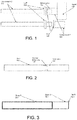
- a vascular graft 102 that comprises a first component 101 equipped with a suturing cuff 105 and a second component 102 equipped with another suturing cuff 103.
- First component 101 could be attached to a vessel 104 using commonly practiced suturing techniques or any other mechanical or non mechanical anastomotic method.
- first component 101 is made from a material that enhances cellular ingrowth in order to enhance graft biocompatibility. As such the material may by example be a porous EPTFE or a woven Dacron material.
- the second component 102 may be smaller in diameter and equipped with a suturing cuff 103 to allow easy joining of first component 101 and second component 102 by means of commonly used sutures or any other mechanical or non-mechanical anastomotic methods.
- the distal tip of the second component 102 typically protrudes inside the first component 101 and is somewhat concentric forming a gutter type circular annulus in between component 101 and component 102. Blood cells may deposit in this gutter and will as intended define the transition/boundary/seam between the cell ingrown to the smooth non cell ingrown area.
- second component 102 is made out of material that within the inner lumen inhibits cellular ingrowth or attachment, e.g. by a smooth and thin Silicone layer; therefore cellular ingrowth will be limited to first component 101.
- the first component 101 has been designed by its stiffness and potentially bellowed structure to serve as a shock absorbing agent for any blood pumping device, which may be attached to component 102.
- the shock absorbing agent manages to absorb any flow/pressure induced axial movement and as such helps to facilitate uninterrupted cell ingrowth in the preferred region. As such motion induced by the pumping device will not disturb the ingrowth, which may lead to continuous cell overgrowth, narrowing of the orifice and to irregular granular tissue, which also could dislodge and create ischemic events.
- ingrowth into first component 101 is wanted, ingrowth onto the outside surface of first component 101 has to be avoided by cell inhibiting surface agents e.g. Silicone coating, since an overgrowth onto the outside of first component 101 could otherwise lead to target vessel deformation, which inherently may limit the orifice of the vessel near the anastomosis.
- Vortex area 106 serves as an area to limit the continual ingrowth or cellular attachment at vortex area 106.
- vascular graft 107 that is formed from a single or multiple tubular components that have similar inner diameter.
- Internal deformity 108 could be integral or added at a later stage of the graft manufacturing to form a "neck down" area in the inner lumen of graft 107.
- Inner deformity 108 serves as a bump to create a vortex in its proximity to inhibit cellular ingrowths, cellular attachment, and/or cellular deposit.
- the two sections of graft 107 separated by inner deformity 108 could be similar or different in biological characteristics, mechanical characteristics, and/or physical reaction to blood contact. While the area of graft 107 distal to internal deformity 108 may be surface treated to inhibit cellular ingrowth, the proximal area is designed to promote cellular ingrowth from the vessel onto the graft.
- vascular graft 203 that is formed by one or multiple zones, for example first zone 201 and a second zone 202, that make a single graft that possesses different biological characteristics, mechanical characteristics, and/or physical reaction to blood contact.
- zone 201 is infiltrated with Silicone rubber to inhibit cellular ingrowth, while zone 202 is of a porous/rough nature promoting ingrowth.
- the mating line between zone 201 and 202 is without a physical step, which avoids any unwanted overgrowth of cells from zone 202 onto zone 201.
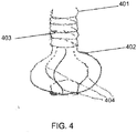
- FIG. 4 shows an embodiment of the invention and illustrates a support stent for a conduit, e.g., for use as a graft with a counterpulsation device (CPD).
- the conduit includes end ports and a passage there between that includes an enlarged area, e.g., bulb shaped portion.
- an enlarged area e.g., bulb shaped portion.
- blood may flow through the conduit in alternating direction.
- the conduit 401 includes a spiral support structure 403 on a first conduit region.
- Conduit 401 includes a bulbous portion 402 having a plurality of support structure 404 coupled thereto.
- Support structures 403 and 404 may be composed of stainless steel wire and may be coupled to the conduit via sutures in accordance with exemplary embodiments.
- the bulbous portion 402 may be flexible inwardly and outwardly to permit washing of the transition region.
- the bulbous portion 402 may be fabricated using a graft, such as a 20 mm graft, that is cut and sewn into the bulb shape illustrated in FIG. 4 .
- the conduit may be supported by a stent structure.
- the support structure includes a first portion that includes one or more support struts shaped to form the bulb portion.
- the outer surface of the material of the bulb portion of the conduit e.g., PTFE or other suitable material
- this arrangement allows the bulb portion of the conduit to flex, e.g., to promote washing of the conduit passage
- the support stent may include a second portion that supports a non-bulb shaped portion of the conduit (e.g., a portion with a substantially constant cross section).
- the second portion may include a spiral shaped support structure.
- the struts of the first portion of the support structure may be connected to the second portion of the support structure.
- the support stent may be made of any suitable material (e.g., a biocompatible material with sufficient structural properties to support the conduit), including e.g., stainless steel or a shape memory material such as Nitinol.
- the conduit may be formed by one or multiple zones, for example first zone and a second zone, that make a single graft that possesses different biological characteristics, mechanical characteristics, and/or physical reaction to blood contact.
- the first zone is infiltrated with Silicone rubber to inhibit cellular ingrowth, while the second zone is of a porous/rough nature promoting ingrowth.
- the mating line between zones may be without a physical step, which avoids any unwanted overgrowth of cells from the first zone to the second zone.
- Other embodiments may feature other transition shapes.
- the first zone may correspond to the bulb shaped portion while the second zone corresponds to the other portion, or vice versa.
- FIG. 5 One form of a counterpulsation system usable with embodiments disclosed herein is shown in FIG. 5 .
- a pump 10 is implanted in a pacemaker pocket on the patient's right side. Blood fills the pump 10 on one side and air or other fluid fills a sac or bladder (not shown) on the other side of the pump 10.
- An air drive line 12 is tunneled from the pacemaker pocket to a skin exit site 14, so the entire pump 10 is under the skin and can remain there chronically. After the driveline 12 exits the skin. It is attached to a small air drive unit 16 that controls shuttling of pressurized air in and out of the pump 10.
- a void in the pump 10 may be formed with the sac or bladder.
- the void fills with air as the heart beats (less cardiac work in ejecting blood) and empties to return blood into the circulation (more flow to the patient).
- the pump 10 is attached to the circulation with a conduit 20.
- the conduit 20 shuttles blood between the patient's circulatory system and the pump 10. This situation allows a patient to have chronic counterpulsation with full mobility. For a patient with severe and potentially non-reversible cardiac dysfunction, this is a great advantage as it is possible to live a relatively normal life, apart from the need to carry a small battery powered drive console 16.
- the blood is shuttled in and out of the pump 10 with a conduit 20, which is connected, to the circulation.
- this conduit 20 There are a number of considerations related to implantation and use of this conduit 20.
- a second potential difficulty with a conduit in this situation is that it will typically be sewn to the subclavian artely 22 or axillary artery which is located beneath the clavicle and often quite deep, so it is technically difficult for a surgeon to suture the end of the conduit 20 to the artery 22.
- the problem of a conduit with bidirectional flow relates to the responses of blood and tissues to the interfaces with synthetic materials and the response is dependent on the direction of blood flow.
- Many medical devices such as blood pumps, are connected to the patient's circulation with artificial graft material such as polyester materials like Dacron(R) or expanded, porous Teflon(R) (ePTFE) that will promote tissue or cell ingrowth.
- graft material such as polyester materials like Dacron(R) or expanded, porous Teflon(R) (ePTFE) that will promote tissue or cell ingrowth.
- the inside of blood pumps is generally smooth and composed of metals or plastics.
- a synthetic graft such as polyester
- the interface where the pump meets the conduit is a stable junction and there tends to be little problem when blood flows forward through this junction.
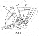
- FIG. 8 shows one exemplary solution in a cross-sectional view.
- the subclavian artery 22 is shown at the top of the figure.
- a "bubble" or enlarged area 24 of Dacron®, Teflon® or other material is sewn to the artery 22.
- a silicone or other smooth material conduit portion 26 is connected to the other side of the enlarged area 24. Rather than a direct junction, a special Interface is created.
- the smooth silicone surface portion 26 extends with a tip portion 26a several millimeters inside the enlarged area 24 of fabric or other material. The walls of the silicone tip portion 26a do not contact the fabric or material of the enlarged area or bubble 24, this avoids a silicone-to-fabric (or smooth-to-rough) point of contact.
- Heart valves have been constructed with arrangements to avoid tissue ingrowth into the valve by creating an elevation - so that there is not a continuous connection between the fabric surface and the smooth surface. This elevation prevents tissue from growing over into junction point and creating a point where platelets and fibrin are deposited.
- the use of a small washer of material may also be of use.
- FIG. 12 shows a small washer 28 around the base of the tip 26a that may help arrest the attachment of blood elements.
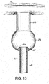
- FIG. 13 shows that this arrangement of the "bubble" or enlarged area 24a of graft material is located away from the anastomosis. Specifically, enlarged area 24a is coupled to or includes an extension 24b that is anastomosed to the artery 22. Other features may be as described previously.
- FIG. 14A and 14B show a similar arrangement can be made at the junction of the pump 10.
- the plastic, metal or other smooth surfaced junction or tip portion 10a of the pump 10 is separated from the rough surface of the enlarged graft material by a bubble interface 24a.
- An extension 24b of the graft material is sewn on the artery 22 ( FIG. 13 ) as previously described.
- Another extension 24c on the opposite end may facilitate connection to the pump interface or tip portion 1Oa, along with a suitable connector 28.
- the junction or Interface 10a which serves as an inlet/outlet port that extends into, but does normally not contact, the graft material 24a in use.
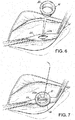
- FIG. 6 and 7 Such a solution is shown in FIG. 6 and 7 .
- a graft element form from material such as described above is sewn to the artery.
- the graft element 30 has a flange 32 at one end.
- the element 30 is small and easy to move around, so does not obscure the view of the surgeon.
- FIG. 7 shows that it is easy to sew this element 30 around an opening 22a on the artery 22.
- FIG. 8 shows how a junction between the silicone material portion 26 of the conduit 20 and the graft element 30 is recreated when a rim or flange 34 of sewing material or graft material, for example, of the conduit portion 26 is affixed to the flange 32 on the element 30 previously anastomosed to the artery 22.
- FIG. 9 shows how the two flanges 32, 34 are sewn together. This is a very easy anastomosis to perform.
- flanges 32, 34 could be joined not just by sutures but by staples, clips, glues, clamps etc.
- FIG. 10A shows a side cross sectional view of the two flanges 32, 34 coming together.
- FIG. 10B shows how the bubble or enlarged connector 30 does not have to be flat
- the bubble or enlarged area 36 is quite useful as it allows the graft to move or "swivel" inside the bubble 36 and still not contact the wall of the bubble 36.
- FIG. 10B also shows clips or staples 38 attaching the connector 30 to the artery 22 and attaching the flanges 32, 34 together.
- the conduit portion 26 does not have to be entirely silicone. It could have any Inner core that presents a compatible surface to the exposed blood.
- the inside could be metal, have a metal spiral reinforcement, etc. it could also have graft material inside like ePTFE or other polyester.
- the smooth surface does not have to be silicone. This is used as representative of a smooth surface.
- the surface could be a metal or plastic (such as in the pump connection shown in FIGs 14A and 14B .)
- FIG. 11 shows a bubble or enlarged area 40 constructed by "splitting" the bubble In the middle of the hemisphere. It could be equally possible in form the junction 42 anywhere in this arrangement; the location at the hemisphere is merely an example.
- the terms used are basically smooth (silicone, plastics, metals) and rough or textured surfaces (Dacron, Teflon, ePTFE). It is also possible to have a tightly woven or knitted material that is typically called a textile, but could function as a smooth surface.
- conduits may also be important to prevent these conduits from collapsing as they can be located below the skin and could be crushed by a patient lying on them. Reinforcement of the conduits with plastic or wire spirals or rings can be used here. In addition, extra thicknesses of polymer or plastic could be added make them stronger.
Landscapes
- Health & Medical Sciences (AREA)
- Engineering & Computer Science (AREA)
- Heart & Thoracic Surgery (AREA)
- Life Sciences & Earth Sciences (AREA)
- Biomedical Technology (AREA)
- Veterinary Medicine (AREA)
- Animal Behavior & Ethology (AREA)
- General Health & Medical Sciences (AREA)
- Public Health (AREA)
- Cardiology (AREA)
- Hematology (AREA)
- Mechanical Engineering (AREA)
- Anesthesiology (AREA)
- Vascular Medicine (AREA)
- Surgery (AREA)
- Nuclear Medicine, Radiotherapy & Molecular Imaging (AREA)
- Medical Informatics (AREA)
- Molecular Biology (AREA)
- Oral & Maxillofacial Surgery (AREA)
- Transplantation (AREA)
- Prostheses (AREA)
- External Artificial Organs (AREA)
- Joining Of Building Structures In Genera (AREA)
- Piles And Underground Anchors (AREA)
- Materials For Medical Uses (AREA)
Claims (8)
- Gefäßtransplantat, das Folgendes umfasst:mindestens eine Leitung (401) mit einem ersten Leitungsbereich und einem zweiten Leitungsbereich, wobei der zweite Leitungsbereich Folgendes umfassteinen bauchigen Abschnitt (402) in Bezug auf den ersten Leitungsbereich,wobei der erste Leitungsbereich einen im Wesentlichen konstanten Durchmesser aufweist und mit einem proximalen Ende des zweiten Leitungsbereichs verbunden ist und wobei der Durchmesser des ersten Leitungsbereichs und ein Durchmesser in dem zweiten Leitungsbereich distal von dem bauchigen Abschnitt (402) im Wesentlichen gleich sind;mindestens eine erste Stützstrebe (403), die in dem ersten Leitungsbereich angeordnet ist, wobei die mindestens eine erste Stützstrebe (403) in einer spiralförmigen Konfiguration ausgebildet ist; undmindestens eine zweite Stützstrebe (404), die in dem zweiten Leitungsbereich angeordnet ist.
- Gefäßtransplantat nach Anspruch 1, wobei die mindestens eine zweite Stützstrebe (404) an eine Außenwand des bauchigen Abschnitts (402) des zweiten Leitungsbereichs angenäht ist.
- Gefäßtransplantat nach Anspruch 1, wobei die mindestens eine zweite Stützstrebe (404) aus rostfreien Stahldrähten besteht.
- Gefäßtransplantat nach Anspruch 1, ferner umfassend ein Blutflussunterstützungssystem, das mit der mindestens einen Leitung verbunden ist.
- Gefäßtransplantat nach Anspruch 1, wobei der erste Leitungsbereich ein erstes Material und der zweite Leitungsbereich ein zweites, vom ersten Material verschiedenes Material enthält.
- Gefäßtransplantat nach Anspruch 5, wobei das erste Material Silikonkautschuk enthält.
- Gefäßtransplantat nach Anspruch 5, wobei das zweite Material poröses ePTFE enthält.
- Gefäßtransplantat nach Anspruch 5, wobei das zweite Material ein gewebtes Polyestermaterial enthält.
Priority Applications (3)
| Application Number | Priority Date | Filing Date | Title |
|---|---|---|---|
| DK21201283.5T DK4011325T3 (da) | 2012-08-10 | 2013-08-09 | Indretning til forankring af transplantat |
| EP24214595.1A EP4509163A3 (de) | 2012-08-10 | 2013-08-09 | Implantatankervorrichtungen, systeme und verfahren |
| EP21201283.5A EP4011325B1 (de) | 2012-08-10 | 2013-08-09 | Transplantatankervorrichtung |
Applications Claiming Priority (3)
| Application Number | Priority Date | Filing Date | Title |
|---|---|---|---|
| US201261681988P | 2012-08-10 | 2012-08-10 | |
| PCT/US2013/054398 WO2014026146A1 (en) | 2012-08-10 | 2013-08-09 | Graft anchor devices, systems and methods |
| EP13828518.4A EP2882373B8 (de) | 2012-08-10 | 2013-08-09 | Vorrichtung zur verankerung von implantaten |
Related Parent Applications (2)
| Application Number | Title | Priority Date | Filing Date |
|---|---|---|---|
| EP13828518.4A Division EP2882373B8 (de) | 2012-08-10 | 2013-08-09 | Vorrichtung zur verankerung von implantaten |
| EP13828518.4A Division-Into EP2882373B8 (de) | 2012-08-10 | 2013-08-09 | Vorrichtung zur verankerung von implantaten |
Related Child Applications (2)
| Application Number | Title | Priority Date | Filing Date |
|---|---|---|---|
| EP21201283.5A Division EP4011325B1 (de) | 2012-08-10 | 2013-08-09 | Transplantatankervorrichtung |
| EP24214595.1A Division EP4509163A3 (de) | 2012-08-10 | 2013-08-09 | Implantatankervorrichtungen, systeme und verfahren |
Publications (2)
| Publication Number | Publication Date |
|---|---|
| EP3351209A1 EP3351209A1 (de) | 2018-07-25 |
| EP3351209B1 true EP3351209B1 (de) | 2021-10-13 |
Family
ID=50068611
Family Applications (4)
| Application Number | Title | Priority Date | Filing Date |
|---|---|---|---|
| EP24214595.1A Pending EP4509163A3 (de) | 2012-08-10 | 2013-08-09 | Implantatankervorrichtungen, systeme und verfahren |
| EP21201283.5A Active EP4011325B1 (de) | 2012-08-10 | 2013-08-09 | Transplantatankervorrichtung |
| EP13828518.4A Active EP2882373B8 (de) | 2012-08-10 | 2013-08-09 | Vorrichtung zur verankerung von implantaten |
| EP18150633.8A Active EP3351209B1 (de) | 2012-08-10 | 2013-08-09 | Implantatankervorrichtung |
Family Applications Before (3)
| Application Number | Title | Priority Date | Filing Date |
|---|---|---|---|
| EP24214595.1A Pending EP4509163A3 (de) | 2012-08-10 | 2013-08-09 | Implantatankervorrichtungen, systeme und verfahren |
| EP21201283.5A Active EP4011325B1 (de) | 2012-08-10 | 2013-08-09 | Transplantatankervorrichtung |
| EP13828518.4A Active EP2882373B8 (de) | 2012-08-10 | 2013-08-09 | Vorrichtung zur verankerung von implantaten |
Country Status (8)
| Country | Link |
|---|---|
| US (4) | US10143571B2 (de) |
| EP (4) | EP4509163A3 (de) |
| JP (6) | JP6488234B2 (de) |
| AU (3) | AU2013299398B9 (de) |
| CA (2) | CA3113910C (de) |
| DK (2) | DK4011325T3 (de) |
| ES (3) | ES2711963T3 (de) |
| WO (1) | WO2014026146A1 (de) |
Families Citing this family (34)
| Publication number | Priority date | Publication date | Assignee | Title |
|---|---|---|---|---|
| DK4011325T3 (da) | 2012-08-10 | 2025-02-03 | Abiomed Inc | Indretning til forankring af transplantat |
| EP2952142B1 (de) | 2014-06-06 | 2017-09-06 | Cook Medical Technologies LLC | Vorrichtung zur ausbildung einer fistel zwischen blutgefässen |
| DE102016209871A1 (de) | 2016-06-06 | 2017-12-07 | Robert Bosch Gmbh | Stanzvorrichtung und Verfahren zum Stanzen eines Lumens und Implantieren einer Implantateinrichtung |
| EP3634528B1 (de) | 2017-06-07 | 2023-06-07 | Shifamed Holdings, LLC | Intravaskuläre fluidbewegungsvorrichtungen, systeme und verwendungsverfahren |
| US11511103B2 (en) | 2017-11-13 | 2022-11-29 | Shifamed Holdings, Llc | Intravascular fluid movement devices, systems, and methods of use |
| DE102018201030B4 (de) | 2018-01-24 | 2025-10-16 | Kardion Gmbh | Magnetkuppelelement mit magnetischer Lagerungsfunktion |
| EP3746149B1 (de) | 2018-02-01 | 2025-08-06 | Shifamed Holdings, LLC | Intravaskuläre blutpumpen |
| US12491356B2 (en) | 2018-03-20 | 2025-12-09 | Second Heart Assist, Inc. | Circulatory assist pump |
| JP2021518249A (ja) | 2018-03-20 | 2021-08-02 | セカンド・ハート・アシスト・インコーポレイテッド | 循環補助ポンプ |
| DE102018206754A1 (de) | 2018-05-02 | 2019-11-07 | Kardion Gmbh | Verfahren und Vorrichtung zur Bestimmung der Temperatur an einer Oberfläche sowie Verwendung des Verfahrens |
| DE102018206724A1 (de) | 2018-05-02 | 2019-11-07 | Kardion Gmbh | Energieübertragungssystem und Verfahren zur drahtlosen Energieübertragung |
| DE102018206750A1 (de) | 2018-05-02 | 2019-11-07 | Kardion Gmbh | Vorrichtung zur induktiven Energieübertragung in einen menschlichen Körper und deren Verwendung |
| DE102018206727A1 (de) | 2018-05-02 | 2019-11-07 | Kardion Gmbh | Energieübertragungssystem und Empfangseinheit zur drahtlosen transkutanen Energieübertragung |
| DE102018206731A1 (de) | 2018-05-02 | 2019-11-07 | Kardion Gmbh | Vorrichtung zur induktiven Energieübertragung in einen menschlichen Körper und Verwendung der Vorrichtung |
| DE102018206725A1 (de) | 2018-05-02 | 2019-11-07 | Kardion Gmbh | Empfangseinheit, Sendeeinheit, Energieübertragungssystem und Verfahren zur drahtlosen Energieübertragung |
| DE102018208564A1 (de) | 2018-05-30 | 2019-12-05 | Kardion Gmbh | Steuerbare Einführungshülse |
| DE102018208555A1 (de) | 2018-05-30 | 2019-12-05 | Kardion Gmbh | Vorrichtung zum Verankern eines Herzunterstützungssystems in einem Blutgefäß, Verfahren zum Betreiben und Herstellverfahren zum Herstellen einer Vorrichtung und Herzunterstützungssystem |
| DE102018208537A1 (de) | 2018-05-30 | 2019-12-05 | Kardion Gmbh | Vorrichtung zum Anbinden eines Herzunterstützungssystems an eine Einführeinrichtung und Verfahren zum Herstellen einer Vorrichtung zum Anbinden eines Herzunterstützungssystems an eine Einführeinrichtung |
| DE102018211297A1 (de) | 2018-07-09 | 2020-01-09 | Kardion Gmbh | Herzunterstützungssystem und Verfahren zur Überwachung der Integrität einer Haltestruktur eines Herzunterstützungssystems |
| WO2020028537A1 (en) | 2018-07-31 | 2020-02-06 | Shifamed Holdings, Llc | Intravascaular blood pumps and methods of use |
| WO2020073047A1 (en) | 2018-10-05 | 2020-04-09 | Shifamed Holdings, Llc | Intravascular blood pumps and methods of use |
| WO2021011473A1 (en) | 2019-07-12 | 2021-01-21 | Shifamed Holdings, Llc | Intravascular blood pumps and methods of manufacture and use |
| US11654275B2 (en) | 2019-07-22 | 2023-05-23 | Shifamed Holdings, Llc | Intravascular blood pumps with struts and methods of use and manufacture |
| US12465748B2 (en) | 2019-08-07 | 2025-11-11 | Supira Medical, Inc. | Catheter blood pumps and collapsible pump housings |
| WO2021062260A1 (en) | 2019-09-25 | 2021-04-01 | Shifamed Holdings, Llc | Catheter blood pumps and collapsible blood conduits |
| US11724089B2 (en) | 2019-09-25 | 2023-08-15 | Shifamed Holdings, Llc | Intravascular blood pump systems and methods of use and control thereof |
| EP4501393A3 (de) | 2019-09-25 | 2025-04-09 | Shifamed Holdings, LLC | Katheterblutpumpen und zusammenklappbare pumpengehäuse |
| EP4072650A4 (de) | 2019-12-11 | 2024-01-10 | Shifamed Holdings, LLC | Absteigende aorten- und hohlvenenblutpumpen |
| EP4077947A4 (de) | 2019-12-19 | 2024-01-10 | Shifamed Holdings, LLC | Intravaskuläre blutpumpen, motoren und fluidsteuerung |
| US11699551B2 (en) | 2020-11-05 | 2023-07-11 | Kardion Gmbh | Device for inductive energy transmission in a human body and use of the device |
| US12589237B2 (en) | 2020-11-20 | 2026-03-31 | Kardion Gmbh | Mechanical circulatory support system with guidewire aid |
| AU2022234898A1 (en) | 2021-03-12 | 2023-09-28 | Stryker European Operations Limited | Neurosurgical methods and systems for detecting and removing tumorous tissue |
| NL2029502B1 (en) * | 2021-10-25 | 2023-05-19 | Umc Utrecht Holding Bv | An anastomosis connector, a group of parts and an applicator |
| US12544560B2 (en) | 2022-01-14 | 2026-02-10 | Second Heart Assist, Inc. | Wireless chronic implant |
Family Cites Families (60)
| Publication number | Priority date | Publication date | Assignee | Title |
|---|---|---|---|---|
| US3667069A (en) | 1970-03-27 | 1972-06-06 | Univ Minnesota | Jet pump cardiac replacement and assist device and method of at least partially replacing a disabled right heart |
| US3871471A (en) | 1973-03-09 | 1975-03-18 | Walter C Wong | Auxiliary system for decelerating vehicle |
| US4240409A (en) | 1979-02-21 | 1980-12-23 | Thermo Electron Corporation | Apparatus for assisting circulation of blood |
| US4573576A (en) | 1983-10-27 | 1986-03-04 | Krol Thomas C | Percutaneous gastrostomy kit |
| JPS6096260A (ja) * | 1983-10-31 | 1985-05-29 | 日本ゼオン株式会社 | 変形自在のカニユ−レ |
| US5084064A (en) * | 1989-06-15 | 1992-01-28 | Abiomed Cardiovascular, Inc. | Surgical cuff |
| US5327885A (en) | 1991-10-08 | 1994-07-12 | Griffith James M | Combination catheter for invasive probe delivery and balloon dilation |
| JP3335668B2 (ja) | 1992-06-12 | 2002-10-21 | テルモ株式会社 | 人工血管 |
| GB9510967D0 (en) * | 1995-05-31 | 1995-07-26 | Harris Peter L | Vascular prostheses |
| US5728131A (en) * | 1995-06-12 | 1998-03-17 | Endotex Interventional Systems, Inc. | Coupling device and method of use |
| US5849036A (en) * | 1996-03-29 | 1998-12-15 | Zarate; Alfredo R. | Vascular graft prosthesis |
| US6488692B1 (en) | 1996-09-16 | 2002-12-03 | Origin Medsystems, Inc. | Access and cannulation device and method for rapidly placing same and for rapidly closing same in minimally invasive surgery |
| US6015431A (en) * | 1996-12-23 | 2000-01-18 | Prograft Medical, Inc. | Endolumenal stent-graft with leak-resistant seal |
| US5843166A (en) | 1997-01-17 | 1998-12-01 | Meadox Medicals, Inc. | Composite graft-stent having pockets for accomodating movement |
| GB9709967D0 (en) | 1997-05-17 | 1997-07-09 | Harris Peter L | Prosthetic grafts |
| CA2206644A1 (en) * | 1997-05-30 | 1998-11-30 | L. Conrad Pelletier | Ventricular assist device comprising enclosed-impeller axial flow blood pump |
| US6390969B1 (en) | 1997-10-09 | 2002-05-21 | Orqis Medical Corporation | Implantable heart assist system and method of applying same |
| US6027530A (en) | 1997-12-24 | 2000-02-22 | Baxter International Inc. | System, apparatus and method for chemical fixation of stentless cardiac valvular bioprostheses |
| US6887268B2 (en) * | 1998-03-30 | 2005-05-03 | Cordis Corporation | Extension prosthesis for an arterial repair |
| CN1303250A (zh) * | 1998-05-29 | 2001-07-11 | 拜帕斯公司 | 血管手术方法和装置 |
| NL1010386C2 (nl) | 1998-10-23 | 2000-04-26 | Eric Berreklouw | Anastomose-inrichting. |
| GB9828696D0 (en) * | 1998-12-29 | 1999-02-17 | Houston J G | Blood-flow tubing |
| US6050975A (en) | 1999-02-25 | 2000-04-18 | Thermo Cardiosystems, Inc. | Control of tissue growth in textured blood-contacting surfaces |
| US20020095210A1 (en) | 2001-01-16 | 2002-07-18 | Finnegan Michael T. | Heart pump graft connector and system |
| GB2379996B (en) * | 2001-06-05 | 2004-05-19 | Tayside Flow Technologies Ltd | Flow means |
| JP2003220146A (ja) * | 2002-01-31 | 2003-08-05 | Kawasumi Lab Inc | ステント及びステントグラフト |
| US20030225448A1 (en) * | 2002-05-28 | 2003-12-04 | Scimed Life Systems, Inc. | Polar radiopaque marker for stent |
| US7150758B2 (en) * | 2003-03-06 | 2006-12-19 | Boston Scientific Santa Rosa Corp. | Kink resistant endovascular graft |
| US7108673B1 (en) * | 2003-07-07 | 2006-09-19 | Stan Batiste | A-V dialysis graft construction |
| US20050137614A1 (en) * | 2003-10-08 | 2005-06-23 | Porter Christopher H. | System and method for connecting implanted conduits |
| JP5131796B2 (ja) | 2003-10-24 | 2013-01-30 | 株式会社サンメディカル技術研究所 | 人工血管システム、接続補助具及び血液ポンプシステム |
| US7273446B2 (en) | 2003-10-31 | 2007-09-25 | Spence Paul A | Methods, devices and systems for counterpulsation of blood flow to and from the circulatory system |
| US20050119573A1 (en) | 2003-11-05 | 2005-06-02 | Boris Vilenkin | Method and system for quantification of arterial stenosis |
| GB0402736D0 (en) * | 2004-02-06 | 2004-03-10 | Tayside Flow Technologies Ltd | A drug delivery device |
| US20050267559A1 (en) | 2004-05-11 | 2005-12-01 | De Oliveira Daniel D | Cuffed grafts for vascular anastomosis |
| US7794490B2 (en) | 2004-06-22 | 2010-09-14 | Boston Scientific Scimed, Inc. | Implantable medical devices with antimicrobial and biodegradable matrices |
| US7824358B2 (en) | 2004-07-22 | 2010-11-02 | Thoratec Corporation | Heart pump connector |
| US20100312333A1 (en) * | 2009-04-29 | 2010-12-09 | The Cleveland Clinic Foundation | Apparatus and method for replacing a diseased cardiac valve |
| US9283314B2 (en) | 2005-09-21 | 2016-03-15 | Abiomed, Inc. | Cannula systems |
| US20070167901A1 (en) * | 2005-11-17 | 2007-07-19 | Herrig Judson A | Self-sealing residual compressive stress graft for dialysis |
| JP2007144065A (ja) | 2005-11-30 | 2007-06-14 | Kitamura Seisakusho:Kk | グラフト、及び内装補強材の装着装置 |
| US7438699B2 (en) | 2006-03-06 | 2008-10-21 | Orqis Medical Corporation | Quick priming connectors for blood circuit |
| US7575592B2 (en) | 2006-10-03 | 2009-08-18 | St. Jude Medical, Inc. | Synthetic blood vessel grafts |
| GB0621048D0 (en) * | 2006-10-23 | 2006-11-29 | Anson Medical Ltd | Helical stent graft |
| WO2008073964A2 (en) * | 2006-12-12 | 2008-06-19 | Spence Paul A | Implant, systems and methods for physically diverting material in blood flow away form the head |
| DE102006062360A1 (de) * | 2006-12-22 | 2008-06-26 | Aesculap Ag & Co. Kg | Gewebte Aortensinusprothese mit Bulbus |
| AU2008284279B2 (en) | 2007-08-08 | 2014-03-20 | Cleveland Clinic Foundation | Branched stent graft system |
| US20090076531A1 (en) | 2007-09-18 | 2009-03-19 | Richardson Charles L | Method and apparatus for bypass graft |
| US9107741B2 (en) | 2007-11-01 | 2015-08-18 | Cook Medical Technologies Llc | Flexible stent graft |
| WO2010006186A1 (en) | 2008-07-09 | 2010-01-14 | Grantadler Corporation | Needle for subcutaneous port |
| GB0908614D0 (en) | 2009-05-19 | 2009-06-24 | Tayside Flow Technologies Ltd | A vascular graft |
| WO2011031587A1 (en) * | 2009-09-10 | 2011-03-17 | Boston Scientific Scimed, Inc. | Endoprosthesis with filament repositioning or retrieval member and guard structure |
| US8333727B2 (en) * | 2009-10-08 | 2012-12-18 | Circulite, Inc. | Two piece endovascular anastomotic connector |
| WO2011081814A1 (en) * | 2009-12-28 | 2011-07-07 | Cook Medical Technologies Llc | Endoluminal device with kink-resistant regions |
| US8696738B2 (en) * | 2010-05-20 | 2014-04-15 | Maquet Cardiovascular Llc | Composite prosthesis with external polymeric support structure and methods of manufacturing the same |
| US8696741B2 (en) * | 2010-12-23 | 2014-04-15 | Maquet Cardiovascular Llc | Woven prosthesis and method for manufacturing the same |
| ES2540957T3 (es) | 2011-03-16 | 2015-07-15 | Duke University | Implante arteriovenoso para hemodiálisis con paredes posterior y lateral resistentes a la perforación |
| US20140187853A1 (en) * | 2011-08-11 | 2014-07-03 | Paul A. Spence | Devices, methods and systems for counterpulsation and blood flow conduit connection |
| CA2856400C (en) | 2011-11-23 | 2018-03-06 | Abiomed, Inc. | Use of a counterpulsation device and counterpulsation |
| DK4011325T3 (da) | 2012-08-10 | 2025-02-03 | Abiomed Inc | Indretning til forankring af transplantat |
-
2013
- 2013-08-09 DK DK21201283.5T patent/DK4011325T3/da active
- 2013-08-09 JP JP2015526738A patent/JP6488234B2/ja active Active
- 2013-08-09 WO PCT/US2013/054398 patent/WO2014026146A1/en not_active Ceased
- 2013-08-09 EP EP24214595.1A patent/EP4509163A3/de active Pending
- 2013-08-09 EP EP21201283.5A patent/EP4011325B1/de active Active
- 2013-08-09 ES ES13828518T patent/ES2711963T3/es active Active
- 2013-08-09 CA CA3113910A patent/CA3113910C/en active Active
- 2013-08-09 AU AU2013299398A patent/AU2013299398B9/en active Active
- 2013-08-09 DK DK18150633.8T patent/DK3351209T3/da active
- 2013-08-09 CA CA2891620A patent/CA2891620C/en active Active
- 2013-08-09 ES ES18150633T patent/ES2903290T3/es active Active
- 2013-08-09 EP EP13828518.4A patent/EP2882373B8/de active Active
- 2013-08-09 ES ES21201283T patent/ES3008184T3/es active Active
- 2013-08-09 EP EP18150633.8A patent/EP3351209B1/de active Active
- 2013-08-09 US US14/420,590 patent/US10143571B2/en active Active
-
2017
- 2017-12-21 AU AU2017279705A patent/AU2017279705B2/en active Active
-
2018
- 2018-06-29 US US16/023,927 patent/US10463508B2/en active Active
- 2018-07-26 JP JP2018139947A patent/JP6974271B2/ja active Active
-
2019
- 2019-10-16 US US16/654,510 patent/US11213412B2/en active Active
-
2020
- 2020-05-22 AU AU2020203354A patent/AU2020203354B2/en active Active
- 2020-07-30 JP JP2020129020A patent/JP7027492B2/ja active Active
-
2021
- 2021-12-01 US US17/539,753 patent/US20220202600A1/en active Pending
-
2022
- 2022-02-16 JP JP2022021874A patent/JP7373889B2/ja active Active
-
2023
- 2023-10-20 JP JP2023180669A patent/JP2023178389A/ja active Pending
-
2025
- 2025-11-28 JP JP2025209151A patent/JP2026020372A/ja active Pending
Non-Patent Citations (1)
| Title |
|---|
| None * |
Also Published As
Similar Documents
| Publication | Publication Date | Title |
|---|---|---|
| EP4011325B1 (de) | Transplantatankervorrichtung | |
| EP3536360B1 (de) | Vorrichtungen und systeme für gegenpulsation und blutflussleiteranschluss | |
| HK40075845B (en) | Graft anchor device | |
| HK40075845A (en) | Graft anchor device | |
| HK40013827B (en) | Devices and systems for counterpulsation and blood flow conduit connection |
Legal Events
| Date | Code | Title | Description |
|---|---|---|---|
| PUAI | Public reference made under article 153(3) epc to a published international application that has entered the european phase |
Free format text: ORIGINAL CODE: 0009012 |
|
| STAA | Information on the status of an ep patent application or granted ep patent |
Free format text: STATUS: THE APPLICATION HAS BEEN PUBLISHED |
|
| AC | Divisional application: reference to earlier application |
Ref document number: 2882373 Country of ref document: EP Kind code of ref document: P |
|
| AK | Designated contracting states |
Kind code of ref document: A1 Designated state(s): AL AT BE BG CH CY CZ DE DK EE ES FI FR GB GR HR HU IE IS IT LI LT LU LV MC MK MT NL NO PL PT RO RS SE SI SK SM TR |
|
| STAA | Information on the status of an ep patent application or granted ep patent |
Free format text: STATUS: REQUEST FOR EXAMINATION WAS MADE |
|
| 17P | Request for examination filed |
Effective date: 20190125 |
|
| RBV | Designated contracting states (corrected) |
Designated state(s): AL AT BE BG CH CY CZ DE DK EE ES FI FR GB GR HR HU IE IS IT LI LT LU LV MC MK MT NL NO PL PT RO RS SE SI SK SM TR |
|
| STAA | Information on the status of an ep patent application or granted ep patent |
Free format text: STATUS: EXAMINATION IS IN PROGRESS |
|
| 17Q | First examination report despatched |
Effective date: 20200428 |
|
| GRAJ | Information related to disapproval of communication of intention to grant by the applicant or resumption of examination proceedings by the epo deleted |
Free format text: ORIGINAL CODE: EPIDOSDIGR1 |
|
| STAA | Information on the status of an ep patent application or granted ep patent |
Free format text: STATUS: GRANT OF PATENT IS INTENDED |
|
| GRAP | Despatch of communication of intention to grant a patent |
Free format text: ORIGINAL CODE: EPIDOSNIGR1 |
|
| RIC1 | Information provided on ipc code assigned before grant |
Ipc: A61F 2/07 20130101AFI20210420BHEP Ipc: A61B 17/11 20060101ALI20210420BHEP Ipc: A61F 2/856 20130101ALI20210420BHEP Ipc: A61M 60/857 20210101ALI20210420BHEP Ipc: A61F 2/06 20130101ALN20210420BHEP |
|
| INTG | Intention to grant announced |
Effective date: 20210506 |
|
| RIN1 | Information on inventor provided before grant (corrected) |
Inventor name: SPENCE, PAUL Inventor name: DOWLING, ROB Inventor name: KUNG, BOB Inventor name: HASTIE, CAITLYN Inventor name: SIESS, THORSTEN Inventor name: GRATZ, ERIC Inventor name: SPANIER, GERD |
|
| RAP1 | Party data changed (applicant data changed or rights of an application transferred) |
Owner name: ABIOMED, INC. |
|
| GRAS | Grant fee paid |
Free format text: ORIGINAL CODE: EPIDOSNIGR3 |
|
| GRAA | (expected) grant |
Free format text: ORIGINAL CODE: 0009210 |
|
| STAA | Information on the status of an ep patent application or granted ep patent |
Free format text: STATUS: THE PATENT HAS BEEN GRANTED |
|
| AC | Divisional application: reference to earlier application |
Ref document number: 2882373 Country of ref document: EP Kind code of ref document: P |
|
| AK | Designated contracting states |
Kind code of ref document: B1 Designated state(s): AL AT BE BG CH CY CZ DE DK EE ES FI FR GB GR HR HU IE IS IT LI LT LU LV MC MK MT NL NO PL PT RO RS SE SI SK SM TR |
|
| REG | Reference to a national code |
Ref country code: GB Ref legal event code: FG4D |
|
| REG | Reference to a national code |
Ref country code: CH Ref legal event code: EP |
|
| REG | Reference to a national code |
Ref country code: DE Ref legal event code: R096 Ref document number: 602013079675 Country of ref document: DE |
|
| REG | Reference to a national code |
Ref country code: IE Ref legal event code: FG4D |
|
| REG | Reference to a national code |
Ref country code: AT Ref legal event code: REF Ref document number: 1437567 Country of ref document: AT Kind code of ref document: T Effective date: 20211115 |
|
| REG | Reference to a national code |
Ref country code: DK Ref legal event code: T3 Effective date: 20220105 |
|
| REG | Reference to a national code |
Ref country code: SE Ref legal event code: TRGR |
|
| REG | Reference to a national code |
Ref country code: NL Ref legal event code: FP |
|
| REG | Reference to a national code |
Ref country code: LT Ref legal event code: MG9D |
|
| REG | Reference to a national code |
Ref country code: AT Ref legal event code: MK05 Ref document number: 1437567 Country of ref document: AT Kind code of ref document: T Effective date: 20211013 |
|
| REG | Reference to a national code |
Ref country code: ES Ref legal event code: FG2A Ref document number: 2903290 Country of ref document: ES Kind code of ref document: T3 Effective date: 20220331 |
|
| PG25 | Lapsed in a contracting state [announced via postgrant information from national office to epo] |
Ref country code: RS Free format text: LAPSE BECAUSE OF FAILURE TO SUBMIT A TRANSLATION OF THE DESCRIPTION OR TO PAY THE FEE WITHIN THE PRESCRIBED TIME-LIMIT Effective date: 20211013 Ref country code: LT Free format text: LAPSE BECAUSE OF FAILURE TO SUBMIT A TRANSLATION OF THE DESCRIPTION OR TO PAY THE FEE WITHIN THE PRESCRIBED TIME-LIMIT Effective date: 20211013 Ref country code: FI Free format text: LAPSE BECAUSE OF FAILURE TO SUBMIT A TRANSLATION OF THE DESCRIPTION OR TO PAY THE FEE WITHIN THE PRESCRIBED TIME-LIMIT Effective date: 20211013 Ref country code: BG Free format text: LAPSE BECAUSE OF FAILURE TO SUBMIT A TRANSLATION OF THE DESCRIPTION OR TO PAY THE FEE WITHIN THE PRESCRIBED TIME-LIMIT Effective date: 20220113 Ref country code: AT Free format text: LAPSE BECAUSE OF FAILURE TO SUBMIT A TRANSLATION OF THE DESCRIPTION OR TO PAY THE FEE WITHIN THE PRESCRIBED TIME-LIMIT Effective date: 20211013 |
|
| PG25 | Lapsed in a contracting state [announced via postgrant information from national office to epo] |
Ref country code: IS Free format text: LAPSE BECAUSE OF FAILURE TO SUBMIT A TRANSLATION OF THE DESCRIPTION OR TO PAY THE FEE WITHIN THE PRESCRIBED TIME-LIMIT Effective date: 20220213 Ref country code: PT Free format text: LAPSE BECAUSE OF FAILURE TO SUBMIT A TRANSLATION OF THE DESCRIPTION OR TO PAY THE FEE WITHIN THE PRESCRIBED TIME-LIMIT Effective date: 20220214 Ref country code: PL Free format text: LAPSE BECAUSE OF FAILURE TO SUBMIT A TRANSLATION OF THE DESCRIPTION OR TO PAY THE FEE WITHIN THE PRESCRIBED TIME-LIMIT Effective date: 20211013 Ref country code: NO Free format text: LAPSE BECAUSE OF FAILURE TO SUBMIT A TRANSLATION OF THE DESCRIPTION OR TO PAY THE FEE WITHIN THE PRESCRIBED TIME-LIMIT Effective date: 20220113 Ref country code: LV Free format text: LAPSE BECAUSE OF FAILURE TO SUBMIT A TRANSLATION OF THE DESCRIPTION OR TO PAY THE FEE WITHIN THE PRESCRIBED TIME-LIMIT Effective date: 20211013 Ref country code: HR Free format text: LAPSE BECAUSE OF FAILURE TO SUBMIT A TRANSLATION OF THE DESCRIPTION OR TO PAY THE FEE WITHIN THE PRESCRIBED TIME-LIMIT Effective date: 20211013 Ref country code: GR Free format text: LAPSE BECAUSE OF FAILURE TO SUBMIT A TRANSLATION OF THE DESCRIPTION OR TO PAY THE FEE WITHIN THE PRESCRIBED TIME-LIMIT Effective date: 20220114 |
|
| REG | Reference to a national code |
Ref country code: DE Ref legal event code: R097 Ref document number: 602013079675 Country of ref document: DE |
|
| PG25 | Lapsed in a contracting state [announced via postgrant information from national office to epo] |
Ref country code: SM Free format text: LAPSE BECAUSE OF FAILURE TO SUBMIT A TRANSLATION OF THE DESCRIPTION OR TO PAY THE FEE WITHIN THE PRESCRIBED TIME-LIMIT Effective date: 20211013 Ref country code: SK Free format text: LAPSE BECAUSE OF FAILURE TO SUBMIT A TRANSLATION OF THE DESCRIPTION OR TO PAY THE FEE WITHIN THE PRESCRIBED TIME-LIMIT Effective date: 20211013 Ref country code: RO Free format text: LAPSE BECAUSE OF FAILURE TO SUBMIT A TRANSLATION OF THE DESCRIPTION OR TO PAY THE FEE WITHIN THE PRESCRIBED TIME-LIMIT Effective date: 20211013 Ref country code: EE Free format text: LAPSE BECAUSE OF FAILURE TO SUBMIT A TRANSLATION OF THE DESCRIPTION OR TO PAY THE FEE WITHIN THE PRESCRIBED TIME-LIMIT Effective date: 20211013 Ref country code: CZ Free format text: LAPSE BECAUSE OF FAILURE TO SUBMIT A TRANSLATION OF THE DESCRIPTION OR TO PAY THE FEE WITHIN THE PRESCRIBED TIME-LIMIT Effective date: 20211013 |
|
| PLBE | No opposition filed within time limit |
Free format text: ORIGINAL CODE: 0009261 |
|
| STAA | Information on the status of an ep patent application or granted ep patent |
Free format text: STATUS: NO OPPOSITION FILED WITHIN TIME LIMIT |
|
| 26N | No opposition filed |
Effective date: 20220714 |
|
| PG25 | Lapsed in a contracting state [announced via postgrant information from national office to epo] |
Ref country code: AL Free format text: LAPSE BECAUSE OF FAILURE TO SUBMIT A TRANSLATION OF THE DESCRIPTION OR TO PAY THE FEE WITHIN THE PRESCRIBED TIME-LIMIT Effective date: 20211013 |
|
| PG25 | Lapsed in a contracting state [announced via postgrant information from national office to epo] |
Ref country code: SI Free format text: LAPSE BECAUSE OF FAILURE TO SUBMIT A TRANSLATION OF THE DESCRIPTION OR TO PAY THE FEE WITHIN THE PRESCRIBED TIME-LIMIT Effective date: 20211013 |
|
| PG25 | Lapsed in a contracting state [announced via postgrant information from national office to epo] |
Ref country code: MC Free format text: LAPSE BECAUSE OF FAILURE TO SUBMIT A TRANSLATION OF THE DESCRIPTION OR TO PAY THE FEE WITHIN THE PRESCRIBED TIME-LIMIT Effective date: 20211013 |
|
| PG25 | Lapsed in a contracting state [announced via postgrant information from national office to epo] |
Ref country code: LU Free format text: LAPSE BECAUSE OF NON-PAYMENT OF DUE FEES Effective date: 20220809 |
|
| REG | Reference to a national code |
Ref country code: BE Ref legal event code: MM Effective date: 20220831 |
|
| P01 | Opt-out of the competence of the unified patent court (upc) registered |
Effective date: 20230522 |
|
| PG25 | Lapsed in a contracting state [announced via postgrant information from national office to epo] |
Ref country code: BE Free format text: LAPSE BECAUSE OF NON-PAYMENT OF DUE FEES Effective date: 20220831 |
|
| PG25 | Lapsed in a contracting state [announced via postgrant information from national office to epo] |
Ref country code: HU Free format text: LAPSE BECAUSE OF FAILURE TO SUBMIT A TRANSLATION OF THE DESCRIPTION OR TO PAY THE FEE WITHIN THE PRESCRIBED TIME-LIMIT; INVALID AB INITIO Effective date: 20130809 |
|
| PG25 | Lapsed in a contracting state [announced via postgrant information from national office to epo] |
Ref country code: CY Free format text: LAPSE BECAUSE OF FAILURE TO SUBMIT A TRANSLATION OF THE DESCRIPTION OR TO PAY THE FEE WITHIN THE PRESCRIBED TIME-LIMIT Effective date: 20211013 |
|
| PG25 | Lapsed in a contracting state [announced via postgrant information from national office to epo] |
Ref country code: MK Free format text: LAPSE BECAUSE OF FAILURE TO SUBMIT A TRANSLATION OF THE DESCRIPTION OR TO PAY THE FEE WITHIN THE PRESCRIBED TIME-LIMIT Effective date: 20211013 |
|
| PG25 | Lapsed in a contracting state [announced via postgrant information from national office to epo] |
Ref country code: MT Free format text: LAPSE BECAUSE OF FAILURE TO SUBMIT A TRANSLATION OF THE DESCRIPTION OR TO PAY THE FEE WITHIN THE PRESCRIBED TIME-LIMIT Effective date: 20211013 |
|
| PGFP | Annual fee paid to national office [announced via postgrant information from national office to epo] |
Ref country code: NL Payment date: 20250704 Year of fee payment: 13 |
|
| PGFP | Annual fee paid to national office [announced via postgrant information from national office to epo] |
Ref country code: ES Payment date: 20250909 Year of fee payment: 13 |
|
| PGFP | Annual fee paid to national office [announced via postgrant information from national office to epo] |
Ref country code: DK Payment date: 20250814 Year of fee payment: 13 Ref country code: DE Payment date: 20250702 Year of fee payment: 13 |
|
| PGFP | Annual fee paid to national office [announced via postgrant information from national office to epo] |
Ref country code: IT Payment date: 20250722 Year of fee payment: 13 |
|
| PGFP | Annual fee paid to national office [announced via postgrant information from national office to epo] |
Ref country code: GB Payment date: 20250703 Year of fee payment: 13 |
|
| PGFP | Annual fee paid to national office [announced via postgrant information from national office to epo] |
Ref country code: FR Payment date: 20250703 Year of fee payment: 13 |
|
| PGFP | Annual fee paid to national office [announced via postgrant information from national office to epo] |
Ref country code: CH Payment date: 20250901 Year of fee payment: 13 Ref country code: SE Payment date: 20250702 Year of fee payment: 13 |
|
| PGFP | Annual fee paid to national office [announced via postgrant information from national office to epo] |
Ref country code: IE Payment date: 20250702 Year of fee payment: 13 |
|
| PG25 | Lapsed in a contracting state [announced via postgrant information from national office to epo] |
Ref country code: TR Free format text: LAPSE BECAUSE OF FAILURE TO SUBMIT A TRANSLATION OF THE DESCRIPTION OR TO PAY THE FEE WITHIN THE PRESCRIBED TIME-LIMIT Effective date: 20211013 |