EP3350864B1 - Plaque de séparation pour système électrochimique - Google Patents
Plaque de séparation pour système électrochimique Download PDFInfo
- Publication number
- EP3350864B1 EP3350864B1 EP16770731.4A EP16770731A EP3350864B1 EP 3350864 B1 EP3350864 B1 EP 3350864B1 EP 16770731 A EP16770731 A EP 16770731A EP 3350864 B1 EP3350864 B1 EP 3350864B1
- Authority
- EP
- European Patent Office
- Prior art keywords
- bead
- guide channel
- separator plate
- flank
- arrangement
- Prior art date
- Legal status (The legal status is an assumption and is not a legal conclusion. Google has not performed a legal analysis and makes no representation as to the accuracy of the status listed.)
- Active
Links
- 239000011324 bead Substances 0.000 claims description 243
- 239000000446 fuel Substances 0.000 claims description 19
- 239000012530 fluid Substances 0.000 claims description 17
- 239000002826 coolant Substances 0.000 claims description 13
- 230000007423 decrease Effects 0.000 claims description 10
- 238000007789 sealing Methods 0.000 claims description 8
- 238000007599 discharging Methods 0.000 claims description 3
- 239000011796 hollow space material Substances 0.000 claims 2
- 230000000712 assembly Effects 0.000 description 7
- 238000000429 assembly Methods 0.000 description 7
- 239000012429 reaction media Substances 0.000 description 7
- 230000007704 transition Effects 0.000 description 7
- OKKJLVBELUTLKV-UHFFFAOYSA-N Methanol Chemical compound OC OKKJLVBELUTLKV-UHFFFAOYSA-N 0.000 description 6
- 238000006243 chemical reaction Methods 0.000 description 5
- 239000007789 gas Substances 0.000 description 5
- 238000003825 pressing Methods 0.000 description 5
- 239000007795 chemical reaction product Substances 0.000 description 4
- 239000012528 membrane Substances 0.000 description 4
- UFHFLCQGNIYNRP-UHFFFAOYSA-N Hydrogen Chemical compound [H][H] UFHFLCQGNIYNRP-UHFFFAOYSA-N 0.000 description 3
- QVGXLLKOCUKJST-UHFFFAOYSA-N atomic oxygen Chemical compound [O] QVGXLLKOCUKJST-UHFFFAOYSA-N 0.000 description 3
- 239000001301 oxygen Substances 0.000 description 3
- 229910052760 oxygen Inorganic materials 0.000 description 3
- XLYOFNOQVPJJNP-UHFFFAOYSA-N water Chemical compound O XLYOFNOQVPJJNP-UHFFFAOYSA-N 0.000 description 3
- 238000003466 welding Methods 0.000 description 3
- ULEZWUGQDAQWPT-UHFFFAOYSA-N CCNC1CC1 Chemical compound CCNC1CC1 ULEZWUGQDAQWPT-UHFFFAOYSA-N 0.000 description 2
- 101100390736 Danio rerio fign gene Proteins 0.000 description 2
- LYCAIKOWRPUZTN-UHFFFAOYSA-N Ethylene glycol Chemical compound OCCO LYCAIKOWRPUZTN-UHFFFAOYSA-N 0.000 description 2
- 101100390738 Mus musculus Fign gene Proteins 0.000 description 2
- 238000009792 diffusion process Methods 0.000 description 2
- 229910001220 stainless steel Inorganic materials 0.000 description 2
- 239000010935 stainless steel Substances 0.000 description 2
- 239000000126 substance Substances 0.000 description 2
- OKTJSMMVPCPJKN-UHFFFAOYSA-N Carbon Chemical compound [C] OKTJSMMVPCPJKN-UHFFFAOYSA-N 0.000 description 1
- 229920000049 Carbon (fiber) Polymers 0.000 description 1
- MYMOFIZGZYHOMD-UHFFFAOYSA-N Dioxygen Chemical compound O=O MYMOFIZGZYHOMD-UHFFFAOYSA-N 0.000 description 1
- 239000000853 adhesive Substances 0.000 description 1
- 230000001070 adhesive effect Effects 0.000 description 1
- 239000003570 air Substances 0.000 description 1
- 229910052799 carbon Inorganic materials 0.000 description 1
- 238000001816 cooling Methods 0.000 description 1
- 230000007797 corrosion Effects 0.000 description 1
- 238000005260 corrosion Methods 0.000 description 1
- 230000003247 decreasing effect Effects 0.000 description 1
- 229910001882 dioxygen Inorganic materials 0.000 description 1
- 230000000694 effects Effects 0.000 description 1
- 239000001257 hydrogen Substances 0.000 description 1
- 229910052739 hydrogen Inorganic materials 0.000 description 1
- WGCNASOHLSPBMP-UHFFFAOYSA-N hydroxyacetaldehyde Natural products OCC=O WGCNASOHLSPBMP-UHFFFAOYSA-N 0.000 description 1
- 239000002184 metal Substances 0.000 description 1
- VNWKTOKETHGBQD-UHFFFAOYSA-N methane Chemical compound C VNWKTOKETHGBQD-UHFFFAOYSA-N 0.000 description 1
- 230000000737 periodic effect Effects 0.000 description 1
- 239000005518 polymer electrolyte Substances 0.000 description 1
- 239000012495 reaction gas Substances 0.000 description 1
- 239000004753 textile Substances 0.000 description 1
- 239000002918 waste heat Substances 0.000 description 1
Images


Classifications
-
- H—ELECTRICITY
- H01—ELECTRIC ELEMENTS
- H01M—PROCESSES OR MEANS, e.g. BATTERIES, FOR THE DIRECT CONVERSION OF CHEMICAL ENERGY INTO ELECTRICAL ENERGY
- H01M8/00—Fuel cells; Manufacture thereof
- H01M8/02—Details
- H01M8/0202—Collectors; Separators, e.g. bipolar separators; Interconnectors
- H01M8/0247—Collectors; Separators, e.g. bipolar separators; Interconnectors characterised by the form
- H01M8/0254—Collectors; Separators, e.g. bipolar separators; Interconnectors characterised by the form corrugated or undulated
-
- C—CHEMISTRY; METALLURGY
- C25—ELECTROLYTIC OR ELECTROPHORETIC PROCESSES; APPARATUS THEREFOR
- C25B—ELECTROLYTIC OR ELECTROPHORETIC PROCESSES FOR THE PRODUCTION OF COMPOUNDS OR NON-METALS; APPARATUS THEREFOR
- C25B9/00—Cells or assemblies of cells; Constructional parts of cells; Assemblies of constructional parts, e.g. electrode-diaphragm assemblies; Process-related cell features
- C25B9/60—Constructional parts of cells
- C25B9/65—Means for supplying current; Electrode connections; Electric inter-cell connections
-
- C—CHEMISTRY; METALLURGY
- C25—ELECTROLYTIC OR ELECTROPHORETIC PROCESSES; APPARATUS THEREFOR
- C25B—ELECTROLYTIC OR ELECTROPHORETIC PROCESSES FOR THE PRODUCTION OF COMPOUNDS OR NON-METALS; APPARATUS THEREFOR
- C25B9/00—Cells or assemblies of cells; Constructional parts of cells; Assemblies of constructional parts, e.g. electrode-diaphragm assemblies; Process-related cell features
- C25B9/70—Assemblies comprising two or more cells
- C25B9/73—Assemblies comprising two or more cells of the filter-press type
-
- H—ELECTRICITY
- H01—ELECTRIC ELEMENTS
- H01M—PROCESSES OR MEANS, e.g. BATTERIES, FOR THE DIRECT CONVERSION OF CHEMICAL ENERGY INTO ELECTRICAL ENERGY
- H01M8/00—Fuel cells; Manufacture thereof
- H01M8/02—Details
- H01M8/0202—Collectors; Separators, e.g. bipolar separators; Interconnectors
- H01M8/0204—Non-porous and characterised by the material
- H01M8/0206—Metals or alloys
-
- H—ELECTRICITY
- H01—ELECTRIC ELEMENTS
- H01M—PROCESSES OR MEANS, e.g. BATTERIES, FOR THE DIRECT CONVERSION OF CHEMICAL ENERGY INTO ELECTRICAL ENERGY
- H01M8/00—Fuel cells; Manufacture thereof
- H01M8/02—Details
- H01M8/0202—Collectors; Separators, e.g. bipolar separators; Interconnectors
- H01M8/0247—Collectors; Separators, e.g. bipolar separators; Interconnectors characterised by the form
-
- H—ELECTRICITY
- H01—ELECTRIC ELEMENTS
- H01M—PROCESSES OR MEANS, e.g. BATTERIES, FOR THE DIRECT CONVERSION OF CHEMICAL ENERGY INTO ELECTRICAL ENERGY
- H01M8/00—Fuel cells; Manufacture thereof
- H01M8/02—Details
- H01M8/0202—Collectors; Separators, e.g. bipolar separators; Interconnectors
- H01M8/0258—Collectors; Separators, e.g. bipolar separators; Interconnectors characterised by the configuration of channels, e.g. by the flow field of the reactant or coolant
- H01M8/0265—Collectors; Separators, e.g. bipolar separators; Interconnectors characterised by the configuration of channels, e.g. by the flow field of the reactant or coolant the reactant or coolant channels having varying cross sections
-
- H—ELECTRICITY
- H01—ELECTRIC ELEMENTS
- H01M—PROCESSES OR MEANS, e.g. BATTERIES, FOR THE DIRECT CONVERSION OF CHEMICAL ENERGY INTO ELECTRICAL ENERGY
- H01M8/00—Fuel cells; Manufacture thereof
- H01M8/02—Details
- H01M8/0202—Collectors; Separators, e.g. bipolar separators; Interconnectors
- H01M8/0267—Collectors; Separators, e.g. bipolar separators; Interconnectors having heating or cooling means, e.g. heaters or coolant flow channels
-
- H—ELECTRICITY
- H01—ELECTRIC ELEMENTS
- H01M—PROCESSES OR MEANS, e.g. BATTERIES, FOR THE DIRECT CONVERSION OF CHEMICAL ENERGY INTO ELECTRICAL ENERGY
- H01M8/00—Fuel cells; Manufacture thereof
- H01M8/02—Details
- H01M8/0271—Sealing or supporting means around electrodes, matrices or membranes
-
- Y—GENERAL TAGGING OF NEW TECHNOLOGICAL DEVELOPMENTS; GENERAL TAGGING OF CROSS-SECTIONAL TECHNOLOGIES SPANNING OVER SEVERAL SECTIONS OF THE IPC; TECHNICAL SUBJECTS COVERED BY FORMER USPC CROSS-REFERENCE ART COLLECTIONS [XRACs] AND DIGESTS
- Y02—TECHNOLOGIES OR APPLICATIONS FOR MITIGATION OR ADAPTATION AGAINST CLIMATE CHANGE
- Y02E—REDUCTION OF GREENHOUSE GAS [GHG] EMISSIONS, RELATED TO ENERGY GENERATION, TRANSMISSION OR DISTRIBUTION
- Y02E60/00—Enabling technologies; Technologies with a potential or indirect contribution to GHG emissions mitigation
- Y02E60/30—Hydrogen technology
- Y02E60/50—Fuel cells
Definitions
- the invention relates to a separator plate for an electrochemical system.
- the electrochemical system may, for example, be a fuel cell system, an electrochemical compressor, a humidifier for a fuel cell system or an electrolyzer.
- Known electrochemical systems usually include a plurality of separator plates arranged in a stack so that each two adjacent separator plates include an electrochemical cell or a humidifier cell.
- the separator plates usually each comprise two individual plates which are connected to one another along their rear sides remote from the electrochemical cells or the humidifier cells.
- the Separatorplatten can z. B. the electrical contacting of the electrodes of the individual electrochemical cells (eg., Fuel cells) and / or the electrical connection of adjacent cells serve (series connection of the cells).
- the Separatorplatten can also for deriving To serve heat, which arises in the cells between the Separatorplatten. Such waste heat can arise, for example, in the conversion of electrical or chemical energy in a fuel cell.
- bipolar plates are frequently used as separator plates.
- the separator plates or the individual plates of the separator plates each have at least one passage opening.
- the passage openings of the stacked separator plates which are aligned or at least partially overlapping, then form media channels for supplying media or for discharging media.
- known separator plates further comprise bead arrangements, which are respectively arranged around the passage opening of the separator plate.
- the individual plates of the separator plate may also have channel structures for supplying an active region of the separator plate with one or more media and / or for removing media.
- the active area may, for. B. include or limit an electrochemical cell or a humidifier cell.
- the media may, for example, be fuels (eg hydrogen or methanol), reaction gases (eg air or oxygen) or a cooling medium as supplied media and reaction products and heated cooling medium as discharged media.
- the reaction media i.e., the reaction media, usually on the opposite surfaces of the individual plates, are typically used. Fuel and reaction gases, guided while the cooling medium is passed between the individual plates.
- the flanks of the bead arrangement which is arranged around the passage opening of the separator plate, can have one or more apertures. These openings serve to establish a fluid connection between the passage opening of the separator plate and the active region of the separator plate or between the passage opening of the separator plate and a cavity formed between the individual plates of the separator plate. The cavity is used for. B. for passing a Cooling medium between the individual plates of Separatorplatte.
- the separator plate or at least one of the individual plates may also have one or more ducts which adjoin the openings in the bead flank on an outer side of the bead arrangement and which are in fluid communication with a bead interior via the openings in the bead flank.
- the passage of a medium through the bead arrangement can be made even more targeted by means of such a duct.
- the efficiency of the electrochemical system can be increased.
- the apertures in the bead flanks necessarily require a reduction in the mechanical stability and elasticity of the bead assembly. This is the more significant the lower the bead arrangement is made.
- the smallest possible height of the bead arrangement is advantageous in order to minimize the size of the separator plate stack or to accommodate more cells at the same height of the separator plate stack.
- the present invention is therefore based on the object to provide a Separatorplatte for an electrochemical system, which ensures the best possible mechanical stability and compactness and the most efficient media supply system.
- the duct is formed such that a certain width parallel to the planar surface of the separator plate width of the duct towards the bead assembly at least partially, preferably in the middle 25 percent, in particular in the middle third of the extension of the duct increases.
- the width of the duct is preferably determined in each case at half the height of the duct, wherein the height of the duct is given by the distance of a roof of the duct to the plane plane of the separator.
- the width of the duct is also preferably determined in each case along a cross-sectional area of the duct, which is aligned perpendicular to the longitudinal direction of the duct or perpendicular to the media flow direction through the duct.
- the duct joins the breakthrough in the bead flank in such a way that the cross-sectional area of the duct at the transition of the duct into the bead flank is identical to and coincides with the area of the flare in the bead flank.
- the channel walls forming the duct thus typically pass directly into the bead flank at the edges of the opening in the bead flank.
- the breakthrough in the bead flank, to which the duct adjoins the outside of the bead assembly can be made wider and at the same time lower to the same extent as the duct.
- this can improve the stability and elasticity of the bead arrangement, without the conduit channel cross section having to be reduced. An efficient media passage through the bead flank is thus still guaranteed.
- the duct can thus be designed such that the height of the duct, which is perpendicular to the plane of the plane of the separator plate, decreases at least in sections toward the bead arrangement.
- the duct can be designed such that the cross-sectional area of the duct at least along the middle 25 percent, preferably at least along the middle third of the extension of the duct changes at most 25 percent, preferably at most 20 percent, in particular at most 15 percent.
- the duct extends from an end of the duct which faces away from the bead assembly, which is through an inlet or an outlet of the duct, until it breaks through in the bead flank.
- the inlet or outlet of the duct may be formed, for example, by an opening in the separator plate or on an inner edge, for example a through-opening.
- the end of the conduit channel facing away from the bead assembly may be through an inlet or outlet of the conduit which is disposed on an inner edge of the separator plate which defines or encloses the aforementioned passage opening in the separator plate.
- the inlet or outlet of a duct are not formed as an opening or at an inner edge, they may also be formed by transitions to other structures. These ends of the ducts are preferably provided with significant radii, which serve the transition into the adjacent structure. Therefore, only the middle half, preferably the middle third or the middle 25 percent of the extension of the duct is preferably considered in relevant height and width considerations.
- the duct may be formed such that the width of the duct increases monotonically along the extension of the duct, preferably strictly monotone. This is especially true for the 60 percent of the length of the duct immediately adjacent the bead flank.
- the width of the duct can in particular increase linearly along the extension of the duct.
- the duct may be formed such that the width of the duct increases along the extension of the duct to the bead assembly at least by 10 percent, preferably at least 20 percent. This also applies in particular to the Skein edge immediately adjacent 60 percent of the length of the duct.
- the height of the duct along the extension of the duct can decrease monotonically, preferably strictly monotone. This applies in particular to the middle third of the length of the duct.
- the height of the duct can decrease linearly in particular along the extension of the duct.
- the duct may be formed such that the height of the duct decreases along the extension of the duct to the bead assembly at least by 10 percent, preferably at least 20 percent.
- the opening can extend perpendicularly to the plane of the plane of the separator plate up to a height of up to 80 percent, preferably only up to 70 percent of the height of Beading arrangement amounts.
- the heights in each case relate to the bead arrangement in the unpressed state and are in each case given by the distance from the planar surface plane of the single plate.
- An inlet or outlet of the duct at the end facing away from the bead assembly end of the duct can extend perpendicular to the planar surface plane of the single plate to a height which is at most 90 percent, preferably at most 85 percent, preferably at most 75 percent of the height of the bead assembly.
- the height indications are preferably based on the bead arrangement in the unpressed state and in each case given by the distance from the plane plane of the single plate. Normally, however, the height of the duct at the end remote from the bead assembly end of the duct is always greater than the height of the opening in the bead assembly.
- the duct can at least in sections, z. B. at least along the middle third of the extension of the duct, have a rectangular, trapezoidal or at least partially rounded cross-section.
- the bead arrangement can be designed such that it runs parallel to the plane of the plane of the plate at least in sections, in particular in those areas which, viewed macroscopically, have a rectilinear extent. This results in a comparable stability and elasticity of these areas with those areas that already have a curvature due to the overall direction of the bead, such as in corner areas.
- the wave-like course can then be given a wavelength.
- at least one wave-like section of the bead arrangement extends over at least two wavelengths.
- the opening in the bead flank, to which the duct adjoins the outside of the bead flank is arranged or formed in the region of an inflection point of the wave-like section of the bead arrangement, for. B. in particular in those wave-like sections of the bead assembly in which the bead assembly is macroscopically straight.
- the breakthrough in the bead flank is preferably arranged on a (maximum of the line channel) minimum or maximum of the wave-like extending portion of the bead assembly or trained, so z. B. where an amplitude of the deflection of the wave-like portion of the bead assembly is maximum.
- the separator plate may be formed as a bipolar plate with two interconnected individual plates, wherein the bead arrangement and the duct are formed in at least one of the individual plates.
- the separator plate and / or the individual plates may be formed of metal, preferably of stainless steel.
- the individual plates may be coated at least in sections.
- a perpendicular to the plane plane of the Separator plate or the individual plates certain thickness of the individual plates may each be between 50 .mu.m and 150 .mu.m, preferably between 70 .mu.m and 110 .mu.m.
- the bead arrangement, the duct and the single plate, in which the bead arrangement and the duct are formed, may be integrally formed.
- the bead arrangement and the duct can be formed in the single plate, in particular stamped.
- At least one of the flanks of the bead arrangement may have a multiplicity of openings, to which a conduit duct of the type described above adjoins on the outer side of the bead arrangement, which widen at least in sections towards the bead arrangement.
- a cohesive connection between directly adjacent ducts or at least between some of the immediately adjacent ducts may be formed in the region of the separator between the immediately adjacent ducts each a cohesive connection between the individual plates.
- the cohesive connection may be a soldered connection, an adhesive connection or a welded connection, in particular a laser welding connection.
- the connection can be realized via a continuous line or single short lines or points.
- the interconnected individual plates of the separator plate may be formed and arranged to include a cavity disposed between the individual plates for passage of a cooling medium. This cavity may be in fluid communication with the bead interior.
- At least one of the individual plates may have a structure for guiding a reaction medium on its surface remote from the other individual plate.
- the structure may, for. B. include a plurality of channels which are embossed in the single plate.
- a channel structure in the active area of the Separator plate is also referred to as flow field.
- the single plate can have a further channel structure, which is referred to as distribution area.
- This structure for guiding the reaction medium is usually arranged on the side of the bead arrangement facing away from the passage opening in the separator plate.
- the structure may be in fluid communication with the bead interior via at least one opening in the single plate, e.g. B.
- reaction medium is thus in the above-mentioned structure from the output or to the input of the duct, namely from or to the above opening on a Outside surface of the separator plate out while it is guided in the conduit between the individual plates, ie in the interior of the separator plate.
- the breakthrough in the bead arrangement and the duct of the type described above which adjoins the opening can be arranged on an edge facing away from the passage opening of the separator plate and / or on an edge of the bead arrangement facing the passage plate of the separator plate.
- the bead arrangement may be formed at least in sections such that the bead flanks each enclose an angle of less than 70 degrees, preferably of less than 60 degrees, particularly preferably of less than 50 degrees, with a perpendicularly aligned to the planar surface plane of the separator plate perpendicular direction.
- the bead can also have a convex curvature.
- the bead flanks have a high rigidity, while the bead cover is elastic and deformable, in particular during pressing of the bead arrangement.
- a height of the bead arrangement in the unpressed state can be less than 800 ⁇ m, less than 600 ⁇ m, less than 500 ⁇ m, less than 450 ⁇ m or less than 400 ⁇ m.
- the height of the bead assembly is given by the distance of the bead roof from the plane plane of the separator plate or the respective single plate.
- the electrochemical system may, for. Example, a fuel cell system, an electrochemical compressor, a humidifier for a fuel cell system or an electrolyzer.
- the separator plates of the electrochemical system are stacked and configured such that the passage openings of the separator plates form at least one media channel adapted to supply a medium or to discharge a medium from the stack.
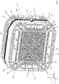
- Fig. 1 shows an inventive electrochemical system 1 with a stack 2 of identical separator plates, which are stacked along a z-direction 7 and clamped between two end plates 3, 4.
- the separator plates are designed here as bipolar plates and each comprise two interconnected individual plates.
- the system 1 is a fuel cell stack.
- Each two adjacent bipolar plates of the stack 2 thus include between them an electrochemical cell which is designed to convert chemical energy into electrical energy.
- the system 1 may also be configured as an electrolyzer, electrochemical compressor or as a humidifier for a fuel cell system.
- Separator plates are also used in these electrochemical systems.
- the structure of these separator plates corresponds to the structure of the bipolar plates explained in more detail here, even if the media guided onto or through the separator plates differ.
- the z-axis 7 spans along with an x-axis 8 and a y-axis 9 right-handed Cartesian coordinate system.
- the end plate 4 has a multiplicity of ports 5, via which media 1 can be supplied to the system 1 and can be discharged from the system 1 via the media. These system 1 can be fed and discharged from the system 1 media can, for.
- fuels such as molecular hydrogen or methanol
- reaction gases such as air or oxygen
- reaction products such as water vapor or oxygen-depleted air
- cooling media such as water and / or glycol
- Fig. 2 shows two immediately adjacent Separatorplatten 10, 11 of the stack 2 from Fig. 1 ,
- recurring features are denoted by the same reference numerals.
- the separator plates 10, 11 are identical. In the following, therefore, only the separator plate 10 will be described in detail. It is thus exemplary of the separator plates of the stack 2.
- the plane planes of the separator plate 10 are aligned along the xy plane.
- the separator plates 10 are formed from two assembled metallic individual plates 10 ', 10 "(see also FIG Fig. 4 ). In Fig. 2 However, only the first individual plates facing the viewer 10 'of the separator plate 10 is visible.
- the individual plates 10 ', 10 "of the separator plate 10 are made of stainless steel sheets which, for example, each have a thickness of 80 ⁇ m determined perpendicular to the plane of the plane of the individual plates
- the individual plates 10', 10" can be used to form the separator plate 10 along their axes facing backs welded together, in particular welded together in sections, be soldered or glued. For example, the individual plates 10 ', 10 "may be connected by laser welding joints.
- the MEA 12 may include a polymer electrolyte membrane (PEM) and one or more gas diffusion layers (GDL).
- PEM polymer electrolyte membrane
- GDL gas diffusion layers
- the GDL are usually oriented toward the separator plates 10, 11 and z. B. formed as a carbon fabric.
- the mutually facing sides of the separator plates 10, 11 close in the compressed state, an electrochemical cell 13 a.
- the cell 13 becomes essentially gas-impermeable permeable membrane, which may be supported by support media, as well as at least one, preferably formed on both sides by a respective diffusion medium made of a textile or carbon nonwoven.
- the separator plate 10 has a plurality of through holes 10a-h.
- the MEA 12 has corresponding passage openings which are aligned with the passage openings 10a-h of the separator plate 10 and with corresponding passage openings of the remaining separator plates of the stack 2, so that the passage openings form two media channels after the pressing of the stack, each with one of the ports 5 out Fig. 1 are in fluid communication. These media channels are used for the supply of media in the electrochemical system 1 and the discharge of media from the electrochemical system. 1
- beading arrangements are formed in the separator plate 10, which are arranged around the through-holes 10a-h.
- the first single plate 10 'of the separator plate 10 facing away from the separator plate 11 has bead arrangements 14a-h around the through openings 10a-h.
- the bead assemblies 14a-h completely surround the through-holes 10a-h, respectively.
- the bead arrangements of the separator plate 10 are in each case formed integrally with the individual plates 10 ', 10 ".
- the bead arrangements of the individual plates 10', 10" are formed in the individual plates, in particular embossed.
- the bead arrangements formed in the individual plates each have a height of only 450 ⁇ m or even only 400 ⁇ m in the unpressed state the respective single plate on the surface facing the bead-roof The bead height advantageously contributes to the compactness of the stack 2 of the system 1.
- the first individual plate 10 'of the separator plate 10 has a structure 17 for guiding reaction medium on its front side facing away from the second individual plate 10 "of the separator plate 10.
- the structure 17 comprises a multiplicity of channels which enter the single plate 10
- the structure 17 is completely surrounded on all sides by the bead arrangement 15 so that the bead arrangement 1 seals off the structure 17 from the environment 17.
- the structure 17 is part of an active region of the single plate 10 'This active region delimits a further electrochemical cell , which is arranged between the separator plate 10 and one of the separator plate 10 in the positive z-direction 7 immediately adjacent another separator plate, which in Fig. 2 not shown.
- the second single plate 10 "of the separator plate 10 has, on its front side remote from the first single plate 10 ', a structure corresponding to the structure 17 for guiding reaction medium.
- the individual plates 10 ', 10 " are designed and arranged such that they enclose therebetween a cavity 18 for the passage of a cooling medium, in particular the cavity 18 being arranged between the individual plates 10', 10" such that they pass through the cavity 18 Cooling medium heat from the active regions of the individual plates 10 ', 10 "can be derived.
- the individual plates 10 ', 10 " also have feedthroughs 19a-h adapted for metered passage or passage of media (eg, fuels, reaction gases, reaction products, or cooling medium) through the bead assemblies 14a-h, 15.
- media eg, fuels, reaction gases, reaction products, or cooling medium
- Some of the feedthroughs, vias 19a and 19e provide fluid communication between the vias 10a and 10e (or the media channels formed therethrough) and the viewer Flow field 17 of the active area of the individual plates 10 ', 10 "of the separator plate 10.
- the remaining passages 19b, 19d, 19f and 19h provide fluid communication between the passage openings 10b, 10d, 10f and 10h (or the media channels formed thereby)
- Fig. 3 shows a modified embodiment of the separator plate 10 with the assembled metallic individual plates 10 ', 10 "facing the viewer, the front of the first single plate 10' can be seen .
- the bead assembly 15 for sealing the active region of the first single plate 10 ' is shown in sections Fig. 3 also has a distributor structure 20. This comprises a multiplicity of channels impressed into the front side of the single plate 10 'and establishes a fluid connection between the through-opening 10a and the active region of the single plate 10', which projects into Fig. 3 connects to the distributor structure 20 at the lower edge of the picture.
- the bead assemblies 14a-c have passages 19a-c for passing media through the bead assemblies 14a-c.
- the medium of the passage opening 10b which is in particular a cooling medium, must cross both the bead 14b and the bead 15. This medium is continuously guided on the side facing away from the viewer side of the single plate 10 '.
- the medium guided transversely to the bead arrangement 14a out of the passage opening 10a between the individual plates 10 ', 10 "and through the passage 19a passes over the opening 33 (see, for example, US Pat. FIGS. 5 to 7 ) into the viewer facing distribution structure 20 a.
- the discharged from the non-visible distribution structure on the opposite surface of the separator plate 10 medium enters through a formed in the second single plate 10 "opening in a duct between the individual plates 10 'and 10" and traverses the bead 14c on the passage 19c and continues to flow in the through hole 10c.
- Fig. 4a shows a section of the separator plate 10 in a perspective view.
- the embossed in the first single plate 10 'bead assembly 14a has two bead flanks 21, 22 and a bead roof 23. Between the bead flanks 21, 22 and the bead roof 23, a bead interior 24 is arranged, which is bounded by the bead flanks 21, 22 and the bead roof 23.
- the passage flank 10a facing bead flank 21 has a plurality of apertures 25 for passing a medium through the bead flank 21.
- the passage opening 10a is in fluid communication with the beaded interior 24 via the apertures 25.
- the bead flank 22 facing away from the passage opening 10a has openings 26 for passing a medium through the bead flank 22.
- the ducts 127 adjoin the openings 26, which are in fluid communication with the bead interior 24 via the openings 26.
- a medium guided in the media channel 10a can thus pass through the openings 25 , 26 and the channels 127 are passed through the bead arrangement 14a and, for example, directed into the active region of the single plate 10 ', as indicated by the arrows
- the non-inventive conduit channels 127 have a constant width, the width of the conduit channels 127 in Fig. 4a in each case parallel to the y-direction 9 at half higher of the line channels 127 is determined.
- FIG. 4b shows a sectional view of the bead assembly 14a according to Fig. 4a , wherein the cutting plane is aligned along the x-z plane and extends longitudinally through one of the non-inventive ducts 127.
- Fig. 4c shows a sectional view of a modified embodiment of the bead assembly 14a, in which non-inventive ducts 127 connect to both bead flanks 21, 22.
- the openings 24, 26 in the bead flanks 21, 22 can impair the stability and elasticity and thus the sealing effect of the bead arrangement 14a. This could possibly be remedied by reducing the openings 25, 26. However, such a reduction would also have an undesirable reduction of the media flow through the bead assembly result.
- Fig. 5 shows a section of the second single plate 10 "facing away from the front of the first single plate 10 'of the separator plate 10. Shown is in particular a portion of the bead assembly 14a, which is embossed in the first single plate 10'
- the single plate 10 'and the bead assembly 14a are integral
- the bead arrangement 14a comprises a first bead flank 21 facing the upper edge of the image, a second bead flank 22 remote from the through hole 10a, and a bead roof 23 connecting the bead flanks 21, 22.
- the first bead flank 21 has a plurality of apertures 25 for passage a medium through the first bead flank 21.
- the second bead flank has a plurality of openings 26 for passing a medium through the second bead flank 22.
- the passage opening 10a at the upper edge of the image is in fluid communication with the bead interior 24 enclosed or confined by the bead flanks 21, 22 and the bead cap 23.
- a medium eg a fuel such as molecular hydrogen, a reaction gas such as molecular Oxygen, a reaction product such as water vapor or a cooling medium
- the media flow can also take place in the opposite direction, ie opposite to the direction indicated by the arrows 35 direction.
- the conduit channels 27 are designed to guide a medium between the individual plates 10 ', 10 "The conduit channels 27 between the passage opening 10a and the apertures 25 in the first bead flank 21 each extend from the passage opening 10a to the apertures 25 in the first bead flank At each of the openings 25 in the first bead flank 21, exactly one inventive conduit 27 connects.
- the conduit channels 27 In order to direct the medium from the bead interior 24 to the active area in a targeted and metered manner, the conduit channels 27 according to the invention again adjoin the apertures 26 in the second bead flank 26 on the outside of the bead arrangement 14a remote from the second individual panel 10 " 65 in the second bead flank 22, exactly one inventive conduit 27 connects.
- the ducts 27 extend between the apertures 26 in the second bead flank 22 and the active region, respectively, from the apertures 26 in the second bead flank 22 to an outlet or inlet 33 of the respective duct 27.
- the outlet or inlet 33 thus forms one, respectively At the outlet or inlet 33, the medium can emerge from the conduit 27 and thereby changes to the opposite surface of the single plate 10 'from the bead assembly 14a end facing away from the conduit 27. In Fig. 5 this is indicated by arrows 36.
- the media flow can also take place in the opposite direction, ie opposite to the direction indicated by the arrows 36 direction.
- the active region of the single plate 10 ' may thus be in fluid communication with the bead interior 24 through the inlets or outlets 33.
- the inlets or outlets 33 are formed as passage openings in the single plate 10 '.
- the ducts 27 are integrally or integrally formed with the single plate 10 '.
- the ducts 27 are formed in the single plate 10 ', in particular stamped.
- the ducts 27 usually each have side flanks 28, 29 and a roof 30.
- the widths 31 ', 31 "of the ducts 27 in each case are parallel to the planar surface plane of the single panel 10' at half the height of the Line channel 27 determines.
- the width 31 ', 31 "of the ducts 27 is determined in each case parallel to the extension direction of the bead arrangement 14a, which extends along the x-direction 8.
- the width 31', 31" of the ducts 27 thus becomes perpendicular to the flow direction of the medium through the duct 27 determined.
- the width 31 ', 31 "of the ducts 27 increases fan-shaped at least in sections, so that the width 31', 31" of the ducts increases at least in sections strictly monotonically, in particular linearly.
- the largest width of the duct 27 is at least 1.5 times the smallest width of the duct.
- the largest width of the duct 27 is usually at least 110 percent or at least 120 percent of the smallest width of the duct 27.
- Fig. 5 extends to the bead assembly 14a approaching section of the ducts 27, in which the width 31 ', 31 "of the ducts 27 increases strictly monotonically, each over a length which is at least two thirds or at least half the length of the respective duct 27 ,
- the ducts 27 are in Fig. 5 in such a way that a height 32 ', 32 "of the line channels 27 perpendicular to the planar plane of the separator plate 10 or of the single plate 10 at least in sections decreases towards the bead arrangement 14.
- the height 32', 32" of the line channels 27 in each case designates the distance of the line Roof 30 of the duct 27 from the plane plane of the separator plate 10 or the single plate 10 '.
- Fig. 5 extends up to the bead assembly 14a approaching Section of the ducts 27, in which the height 32 ', 32 "of the ducts 27 decreases strictly monotonically, each over a length which is at least two-thirds or at least half the length of the respective duct 27.
- the height 32', 32nd "of the ducts 27 at least partially linear from.
- Exemplary are in Fig. 5 two sectional views of one of the ducts 27 shown at two different locations along the course of this duct 27.
- the sectional plane is in each case aligned parallel to the xz plane and thus perpendicular to the planar surface plane of the separator plate 10 or the single plate 10 '.
- the sectional planes are perpendicular to the media flow direction through the duct 27.
- the section plane indicated by the straight line AA is arranged at a first distance from the bead assembly 14a
- the sectional plane indicated by the straight line BB is arranged at a second distance from the bead assembly 14a, wherein the first distance is smaller than the second distance.
- the duct 27 has a width 31 "and a height 32", and in the sectional plane AA, the duct 27 has a width 31 "and a height 32".
- the width 31 ' is greater than the width 31 ", and the height 32' is smaller than the height 31".
- the ducts 27 are formed such that their cross-sectional area is substantially constant at least along the middle third of the extension of the respective duct.
- the ducts 27 are formed such that their cross-sectional area at most along the middle third of their extension relative to the largest cross-sectional area in the middle third changes by more than 20 percent, preferably at most 15 percent or at most 10 percent (the cross-sectional views of Fig. 5 are not necessarily to scale in this respect).
- the openings 25, 26 in the bead flanks 21, 22 extend perpendicularly to the planar surface plane of the separator plate 10 or the single plate 10 'up to a height which is at most 80 percent or at most 70 percent of the height of the sock roof 23.
- the height of the sock roof 23 denotes the distance of the sipe roof 23 from the plane plane of the separator plate 10 or the single plate 10 '.
- the heights are to be determined in each case in the unpressed state of the separator plate 10 or the single plate 10 '.
- the ducts 27 are further formed such that the maximum height of their roof 30 is at most 85 percent or at most 75 percent of the height of the bead assembly 14a, the heights are again to be determined in the unpressed state.
- the single plate 10' is integrally connected to the second single plate 10 ".
- the individual plates 10 ', 10" are the separator plate 10 in the areas 34 or in some of the areas 34 partially connected by laser welding connections. This prevents a gaping of the individual plates 10 ', 10 "perpendicular to the planar surface plane of the separator plate 10 during pressing of the separator plate 10.
- the pressing forces typically attack perpendicular to the plane of the separator plate 10 in the region of the bead assembly 14a.
- the bead assembly 14a extends in a straight direction.
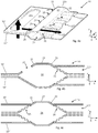
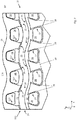
- the bead arrangement 14a or the bead passage 19a according to FIG Fig. 6 differs from the bead assembly 14a and from the bead passage 19a according to Fig. 5 in that the bead arrangement 14a according to FIG Fig. 6 , as well in Fig. 6a as well as in Fig. 6b , Waves, in particular in the manner of a sine wave with constant amplitude.
- the bead arrangement 14a according to FIG Fig. 6 So a periodic course.
- Markings 37 are arranged at a distance of half a wavelength or period length. The markings 37 designate the inflection points in the flanks 21, 22 of the bead arrangement 14a, in which the openings 25, 26 are arranged.
- FIG. 6 in both sub-figures 6a and 6b, two sectional views of the bead passage 19a shown.
- the designated by the straight line CC cutting plane is aligned parallel to the yz axis, and by the straight line DD designated cutting plane is aligned perpendicular to the xy plane and includes with the x-direction 8 an angle of about 20 degrees.
- the sectional plane CC extends along the longitudinal direction of one of the ducts 27. Visible are the bead assembly 14a down in sections severely monotonically decreasing height 32 ', 32 "of the roof 30.
- the height of the duct 27 takes at the transition to the bead flank 21 its lowest value 32'
- the largest height 32 "of the channel roof 30 extends to a height which is about 70 percent of the height of the sock roof 23 here.
- the embodiments of the subfigures 6a and 6b differ in that in the subfigure 6a, in the transition to the passage opening 10a, a region adjoins the conduit channels 27, in which the two individual plates 10 ', 10 "extend substantially parallel to one another . Exit occurs thus over the entire width, and between the continuations of the ducts 27.
- the media inlet and outlet thus takes place directly in or out of the ducts 27.
- the media inlet or outlet extends from or into the passage opening 10a between the individual plates 10 ', 10 ".
- the entry or exit into and out of the flow field 17 takes place on the surface of the separator plate 10 facing the viewer through the openings 33.
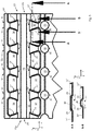
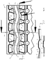
- the bead passage 19b according to Fig. 7 differs from the sip passage 19a according to Fig. 6 in that an edge 38 of the single plate 10 ', which extends to the passage opening 10a and delimits the passage opening 10a, is wave-shaped in sections, in particular in the manner of a sinusoid.
- both the bead arrangement 14a and the edge 38 run in a wave-like manner.
- the corrugated portion of the bead assembly 14a and the corrugated portion of the edge 38 each extend over at least two wavelengths. In the example of Fig. 7
- the corrugated portion of the bead assembly 14a and the corrugated portion of the edge 38 each have the same wavelength.
- FIGS. 5-6 are both at the through hole 10a facing bead edge 21 so also at the side facing away from the passage opening 10a bead edge 22 each according to the invention ducts 27 arranged, which widen in each case to the bead assembly 14a as described.
- the separator plate 10, as in FIG Fig. 7 are the ducts 27 according to the invention each arranged only on one of the bead flanks 21, 22, in the example of Fig. 7 at the bead flank 22.
- the ducts 227 at the bead edge 21 have a different geometry, in which the width of the ducts 227 increases starting from the bead flank 21 and the height decreases simultaneously to the passage opening 10b. It is also conceivable that only some of the bead arrangements 14a-h have the conduit channels 27 according to the invention, while others of the bead arrangements 14a-h have no conduit 27 according to the invention.
- the guide of the medium between the through hole 10b and the bead interior 24 takes place as in the embodiments described above.
- the bead interior 24 is in fluid communication with the previously described cavity 18 via the openings 26 in the second bead edge 18, which is arranged between the individual plates 10 ', 10 "and for passing a cooling medium between the individual plates 10'. , 10 "is set up. On an opening 33 can therefore be omitted here.
- the radius 39 leads to the end 37 of the duct 27.
- FIGS. 8a-f show sectional views of various embodiments of the conduit 27 of the invention from the FIGS. 5-7 ,
- the sectional planes are each aligned perpendicular to the planar surface plane of the single plate 10 'and perpendicular to the media flow direction through the duct 27.
- the illustrated sectional planes are thus each aligned such that they minimize the cross-sectional area of the duct 27.
- Fig. 8a the cross section of the duct 27 is trapezoidal in shape, with straight side flanks 28, 29 and a straight duct roof 30
- Fig. 8b the side edges 28, 29 are straight and the channel roof 30 is concavely curved inwards.
- Fig. 8c the side flanks 28, 29 are straight and the channel roof 30 is subdivided into a plurality of short straight sections, so that the channel roof 30 is flattened with respect to the side flanks 28, 29.
- Fig. 8d shows straight side flanks 28, 29 and a rounded, convexly curved channel roof 30, wherein the curvature of the channel roof 30 smoothly, ie without edges in the straight side edges 28, 29 passes.
- FIG. 8e shows straight side flanks 28, 29 and a convexly curved channel roof 30, wherein the transition of the curvature of the channel roof 30 in the side edges 28, 29 has edges.
- Fig. 8f shows a completely rounded cross-section. The channel roof 30 overhangs the channel convex without flanks.
- the bead arrangements can basically cross sections as in FIGS. 8a-f respectively.
- the channel 27 then corresponds to the bead interior 24, the side edges 28, 29, the bead flanks 21, 22 and the channel roof 30, the s tail roof 23.
- the heights and usually the widths are generally greater in beads 14 than in ducts 27th
- FIGS. 9a-e again show sectional views of various embodiments of the conduit 27 of the invention from the FIGS. 5-7 ,
- the cutting planes are aligned again perpendicular to the planar surface plane of the single plate 10 'and perpendicular to the media flow direction through the duct 27.
- the geometric shape of the cross section of the same conduit 27 can change along its extension.
- the shape of the cross section of the duct 27 in Fig. 9d from a trapezoidal shape to a convexly curved shape.
- Fig. 9b shows that the ducts 27 may be formed asymmetrically.
- the largest height 32 "and the smallest height 32 'of the respective duct 27 are not highlighted.
- the cross section with the greater width has a smaller distance from each the bead assembly 14a as the cross-section with the smaller width.
- FIGS. 9a-e It can thus be clearly seen that the width of the duct 27 determined at half the height of the duct 27 increases towards the bead arrangement 14a, while the height 32 ', 32 "of the duct 27 decreases towards the bead arrangement 14a of the duct 27 takes place, however, in each case in such a way that the cross-sectional area changes along the course of the channel at most by 20 percent, preferably by less than 10 percent each.
Landscapes
- Chemical & Material Sciences (AREA)
- Engineering & Computer Science (AREA)
- Electrochemistry (AREA)
- Chemical Kinetics & Catalysis (AREA)
- Sustainable Development (AREA)
- Sustainable Energy (AREA)
- Life Sciences & Earth Sciences (AREA)
- Manufacturing & Machinery (AREA)
- General Chemical & Material Sciences (AREA)
- Materials Engineering (AREA)
- Metallurgy (AREA)
- Organic Chemistry (AREA)
- Fuel Cell (AREA)
Claims (15)
- Plaque de séparateur (10) pour un système électrochimique (1), comprenant :au moins une ouverture de passage (10a-h) pour la réalisation d'un canal de fluide pour l'introduction du fluide ou pour la dérivation du fluide ;au moins un arrangement de nervures (14a-h) disposé autour de l'au moins une ouverture de passage (10a-h) pour l'étanchéification de l'ouverture de passage (10a-h), au moins un des flancs (21, 22) de l'arrangement de nervures (14a-h) comprenant au moins une percée (25, 26) pour le passage d'un fluide à travers le flanc de nervure (21, 22) ; etau moins un canal de guidage (27) qui se raccorde à un côté externe de l'arrangement de nervures (14a-h) au niveau de la percée (25, 26) dans le flanc de nervure (21, 22) et qui est en liaison fluidique avec un espace interne de la nervure (24) par l'intermédiaire de la percée (25, 26) dans le flanc de nervure (21, 22) ;caractérisée en ce quele canal de guidage (27) est conçu de façon à ce qu'une largeur (31) déterminée du canal de guidage (27), parallèle au plan de surface plane de la plaque de séparateur (10) augmente au moins à certains endroits en direction de l'arrangement de nervures (14a-h).
- Plaque de séparateur (10) selon la revendication 1, caractérisée en ce que le canal de guidage (27) est conçu de façon à ce qu'une hauteur (32) déterminée du canal de guidage (27), perpendiculaire au plan de surface plane de la plaque de séparateur (10), diminue au moins à certains endroits en direction de l'arrangement de nervures (14a-h).
- Plaque de séparateur (10) selon l'une des revendications précédentes, caractérisée en ce que le canal de guidage (27) est conçu de façon à ce qu'une surface de section transversale du canal de guidage (27) varie le long des 25 % centraux de l'extension du canal de guidage (27), de préférence le long du tiers central de l'extension du canal de guidage (27), de 25 % maximum, de préférence de 20 % maximum, plus particulièrement de préférence de 15 % maximum, le canal de guidage (27) s'étendant d'une extrémité opposée à l'arrangement de nervures (14a-h) du canal de guidage jusqu'à la percée (25, 26) dans le flanc de la nervure.
- Plaque de séparateur (10) selon l'une des revendications précédentes, caractérisée en ce que le canal de guidage (27) est conçu de façon à ce que la largeur (31) du canal de guidage (27) augmente de manière monotone le long du canal de guidage (27) au moins sur les 60 %, adjacents au flanc de la nervure (21, 22), de la longueur du canal de guidage, le canal de guidage (27) s'étendant d'une extrémité, opposée à l'arrangement de nervures (14a-h), du canal de guidage (27), jusqu'à la percée (25, 26) dans le flanc de la nervure (21, 22).
- Plaque de séparateur (10) selon l'une des revendications précédentes, caractérisée en ce que le canal de guidage (27) est conçu de façon à ce que la largeur (31) du canal de guidage (27) augmente de manière linéaire.
- Plaque de séparateur (10) selon l'une des revendications 2 à 5, caractérisée en ce que le canal de guidage (27) est conçu de façon à ce que la hauteur du canal de guidage (27) diminue de manière monotone le long du canal de guidage (27), le canal de guidage (27) s'étendant d'une extrémité, opposée à l'arrangement de nervures (14a-h), du canal de guidage (27) jusqu'à la percée (25, 26) dans le flanc de nervure (21, 22).
- Plaque de séparateur (10) selon l'une des revendications précédentes, caractérisée en ce que le canal de guidage (27) est conçu de façon à ce que la largeur (31) du canal de guidage (27) augmente, au moins le long des 60 %, adjacents au flanc de nervure (21, 22), de la longueur du canal de guidage (27), d'au moins 10 %, de préférence d'au moins 20 %, le canal de guidage (27) s'étendant d'une extrémité, opposée à l'arrangement de nervures (14a-h), du canal de guidage (27) jusqu'à la percée (25, 26) dans le flanc de nervure (21, 22).
- Plaque de séparateur (10) selon l'une des revendications précédentes, caractérisée en ce que, dans l'état non compressé de l'arrangement de nervures (14a-h), la percée (25, 26) dans le flanc de nervure (21, 22) arrive, perpendiculairement au plan de surface plane de la plaque de séparateur (10), jusqu'à une hauteur qui représente 80 % maximum, de préférence 70 % maximum de la hauteur de l'arrangement de nervures (14a-h).
- Plaque de séparateur (10) selon l'une des revendications précédentes, caractérisée en ce que, dans l'état non compressé de l'arrangement de nervures (14a-h), le canal de guidage (27) est conçu de façon à ce qu'une entrée ou une sortie du canal de guidage (27), qui forme une extrémité (33, 37, 38), opposée à l'arrangement de nervures (14a-h), du canal de guidage (27), arrive, perpendiculairement au plan de surface plane de la plaque de séparateur (10), jusqu'à une hauteur qui représente 90 % maximum, de préférence 85 % maximum, de préférence 75 % maximum de la hauteur de l'arrangement de nervures (14a-h).
- Plaque de séparateur (10) selon l'une des revendications précédentes, caractérisée en ce que la plaque de séparateur (10) est conçue comme une plaque bipolaire avec deux plaques individuelles (10', 10") reliées entre elles, l'arrangement de nervures (14a-h) et le canal de guidage (27) étant disposés dans au moins une des plaques individuelles (10', 10").
- Plaque de séparateur (10) selon la revendication 10, caractérisée en ce que l'arrangement de nervures (14a-h), le canal de guidage (27) et la plaque individuelle (10', 10"), dans laquelle l'arrangement de nervures (14a-h) et le canal de guidage (27) sont disposés, sont réalisés d'une seule pièce, l'arrangement de nervures (14a-h) et le canal de guidage (27) étant moulés, plus particulièrement estampés, dans la plaque individuelle (10', 10").
- Plaque de séparateur (10) selon la revendication 10 ou 11, caractérisée en ce que les plaques individuelles (10', 10") incluent une cavité (18) pour le passage d'un fluide de refroidissement.
- Plaque de séparateur (10) selon la revendication 12, caractérisée en ce que la cavité (18) est en communication fluidique avec l'intérieur de la nervure (24) pour le passage du fluide de refroidissement.
- Plaque de séparateur (10) selon l'une des revendications précédentes, caractérisée en ce que la percée (25, 26) et le canal de guidage (27) sont disposés au niveau d'un flanc (21, 22), opposé à l'ouverture de passage (10a-h) de la plaque de séparateur (10) et/ou orienté vers l'ouverture de passage (10a-h) de la plaque de séparateur (10), de l'arrangement de nervures (14a-h).
- Système électrochimique (1), plus particulièrement système de cellule à combustible, compresseur électrochimique, humidificateur pour un système de cellule à combustible ou électrolyseur avec une pluralité de plaques de séparateur (10, 11) selon l'une des revendications précédentes, les ouvertures de passage (10a-h) des plaques de séparateur (10, 11) formant au moins un canal de fluide pour l'introduction du fluide ou pour la dérivation du fluide.
Applications Claiming Priority (2)
| Application Number | Priority Date | Filing Date | Title |
|---|---|---|---|
| DE202015104972.2U DE202015104972U1 (de) | 2015-09-18 | 2015-09-18 | Separatorplatte für ein elektrochemisches System |
| PCT/EP2016/072081 WO2017046405A1 (fr) | 2015-09-18 | 2016-09-16 | Plaque de séparation pour système électrochimique |
Publications (2)
| Publication Number | Publication Date |
|---|---|
| EP3350864A1 EP3350864A1 (fr) | 2018-07-25 |
| EP3350864B1 true EP3350864B1 (fr) | 2019-08-21 |
Family
ID=56997475
Family Applications (1)
| Application Number | Title | Priority Date | Filing Date |
|---|---|---|---|
| EP16770731.4A Active EP3350864B1 (fr) | 2015-09-18 | 2016-09-16 | Plaque de séparation pour système électrochimique |
Country Status (7)
| Country | Link |
|---|---|
| US (1) | US10854891B2 (fr) |
| EP (1) | EP3350864B1 (fr) |
| JP (1) | JP6769648B2 (fr) |
| CN (1) | CN108292774B (fr) |
| CA (1) | CA2998675A1 (fr) |
| DE (1) | DE202015104972U1 (fr) |
| WO (1) | WO2017046405A1 (fr) |
Cited By (1)
| Publication number | Priority date | Publication date | Assignee | Title |
|---|---|---|---|---|
| DE102021213135A1 (de) | 2021-11-23 | 2023-05-25 | Robert Bosch Gesellschaft mit beschränkter Haftung | Bipolarplatte für eine Brennstoffzelleneinheit |
Families Citing this family (21)
| Publication number | Priority date | Publication date | Assignee | Title |
|---|---|---|---|---|
| DE202015104973U1 (de) * | 2015-09-18 | 2016-12-20 | Reinz-Dichtungs-Gmbh | Separatorplatte für ein elektrochemisches System |
| DE202016105307U1 (de) * | 2016-09-23 | 2018-01-09 | Reinz-Dichtungs-Gmbh | Strömungsplatte für einen Befeuchter |
| DE202016107302U1 (de) * | 2016-12-22 | 2018-03-27 | Reinz-Dichtungs-Gmbh | Separatorplatte für ein elektrochemisches System |
| DE202017103229U1 (de) | 2017-05-30 | 2018-08-31 | Reinz-Dichtungs-Gmbh | Separatorplatte für ein elektrochemisches System |
| JP6618513B2 (ja) * | 2017-07-21 | 2019-12-11 | 本田技研工業株式会社 | 発電セル |
| DE102018104172A1 (de) * | 2018-02-23 | 2019-08-29 | Elringklinger Ag | Elektrochemische Vorrichtung |
| DE202018103058U1 (de) * | 2018-05-30 | 2019-09-02 | Reinz-Dichtungs-Gmbh | Separatorplatte für ein elektrochemisches System |
| DE202018105617U1 (de) * | 2018-09-28 | 2020-01-03 | Reinz-Dichtungs-Gmbh | Separatorplatte und elektrochemisches System |
| KR20200069452A (ko) | 2018-12-06 | 2020-06-17 | 현대자동차주식회사 | 연료전지용 분리판 조립체 및 이를 포함하는 연료전지 스택 |
| DE202019101145U1 (de) | 2019-02-28 | 2020-05-29 | Reinz-Dichtungs-Gmbh | Separatorplatte für ein elektrochemisches System |
| JP7250408B2 (ja) * | 2019-07-27 | 2023-04-03 | 林 美子 | 水素導管の構造および作製方法 |
| JP7038692B2 (ja) * | 2019-11-25 | 2022-03-18 | 本田技研工業株式会社 | 燃料電池用セパレータ及び発電セル |
| CN111821768B (zh) * | 2020-07-27 | 2022-05-03 | 上海捷氢科技股份有限公司 | 一种分水器和一种燃料电池 |
| JP7247150B2 (ja) * | 2020-09-02 | 2023-03-28 | 株式会社東芝 | 二酸化炭素電解装置および二酸化炭素電解方法 |
| DE102020215022A1 (de) * | 2020-11-30 | 2022-06-02 | Robert Bosch Gesellschaft mit beschränkter Haftung | Bipolarplatte für eine elektrochemische Zelle, Anordnung elektrochemischer Zellen und Verfahren zum Betrieb einer Anordnung elektrochemischer Zellen |
| DE102020215011A1 (de) * | 2020-11-30 | 2022-06-02 | Robert Bosch Gesellschaft mit beschränkter Haftung | Bipolarplatte für eine elektrochemische Zelle, Anordnung elektrochemischer Zellen und Verfahren zum Betrieb der Anordnung elektrochemischer Zellen |
| AT524562B1 (de) * | 2021-08-13 | 2022-07-15 | H2i GreenHydrogen GmbH | Abdichtungsvorrichtung als Zellperipherie für einen Elektrolysezellen-Stack |
| DE102021134038A1 (de) * | 2021-12-21 | 2023-06-22 | Ekpo Fuel Cell Technologies Gmbh | Verfahren zur Herstellung einer Bipolarplattenlage für eine Bipolarplatte einer elektrochemischen Einheit, Bipolarplattenlage für eine Bipolarplatte einer elektrochemischen Einheit und elektrochemische Einheit für eine elektrochemische Vorrichtung |
| DE202022106505U1 (de) | 2022-11-21 | 2024-02-28 | Reinz-Dichtungs-Gmbh | Separatorplatte für ein elektrochemisches System mit einer Entlastungssicke |
| DE202022106651U1 (de) | 2022-11-28 | 2024-03-01 | Reinz-Dichtungs-Gmbh | Separatorplatte mit einer Haltestruktur für einen Steckerstift |
| DE202022107165U1 (de) | 2022-12-21 | 2024-04-02 | Reinz-Dichtungs-Gmbh | Separatorplatte für ein elektrochemisches System mit einer Abstützsicke |
Family Cites Families (10)
| Publication number | Priority date | Publication date | Assignee | Title |
|---|---|---|---|---|
| DE10248531B4 (de) | 2002-10-14 | 2005-10-20 | Reinz Dichtungs Gmbh & Co Kg | Brennstoffzellensystem sowie Verfahren zur Herstellung einer in dem Brennstoffzellensystem enthaltenen Bipolarplatte |
| EP1552573B1 (fr) | 2002-10-14 | 2015-09-02 | REINZ-Dichtungs-GmbH | Systeme electrochimique |
| DE102004009869B4 (de) | 2004-02-26 | 2010-12-30 | Reinz-Dichtungs-Gmbh | Kontaktplatte für Brennstoffzellen, Brennstoffzelle und Brennstoffzellenstapel sowie Verfahren zur Herstellung einer Kontaktplatte |
| JP2006302702A (ja) * | 2005-04-21 | 2006-11-02 | Nissan Motor Co Ltd | セパレータのシール構造およびシール付きセパレータの製造方法 |
| DE102005057045B4 (de) * | 2005-11-30 | 2015-06-03 | Daimler Ag | Bipolarplatte und deren Verwendung in einer Brennstoffzelleneinheit |
| WO2012035585A1 (fr) * | 2010-09-16 | 2012-03-22 | トヨタ自動車株式会社 | Séparateur pour pile à combustible, pile à combustible et procédé de fabrication d'une pile à combustible |
| US8802326B2 (en) * | 2010-11-23 | 2014-08-12 | GM Global Technology Operations LLC | Fuel cell separator plate |
| DE202012004927U1 (de) * | 2012-05-16 | 2013-08-19 | Reinz-Dichtungs-Gmbh | Befeuchter |
| JP5903476B2 (ja) | 2013-11-11 | 2016-04-13 | 本田技研工業株式会社 | 燃料電池 |
| DE202014004456U1 (de) | 2014-05-23 | 2015-05-28 | Reinz-Dichtungs-Gmbh | Metallische Bipolarplatte mit rückfedernder Dichtungsanordnung und elektrochemisches System |
-
2015
- 2015-09-18 DE DE202015104972.2U patent/DE202015104972U1/de not_active Expired - Lifetime
-
2016
- 2016-09-16 WO PCT/EP2016/072081 patent/WO2017046405A1/fr active Application Filing
- 2016-09-16 CA CA2998675A patent/CA2998675A1/fr not_active Abandoned
- 2016-09-16 EP EP16770731.4A patent/EP3350864B1/fr active Active
- 2016-09-16 JP JP2018513649A patent/JP6769648B2/ja active Active
- 2016-09-16 CN CN201680067640.1A patent/CN108292774B/zh active Active
- 2016-09-16 US US15/760,677 patent/US10854891B2/en active Active
Non-Patent Citations (1)
| Title |
|---|
| None * |
Cited By (2)
| Publication number | Priority date | Publication date | Assignee | Title |
|---|---|---|---|---|
| DE102021213135A1 (de) | 2021-11-23 | 2023-05-25 | Robert Bosch Gesellschaft mit beschränkter Haftung | Bipolarplatte für eine Brennstoffzelleneinheit |
| WO2023094087A1 (fr) | 2021-11-23 | 2023-06-01 | Robert Bosch Gmbh | Plaque bipolaire pour une unité de pile à combustible |
Also Published As
| Publication number | Publication date |
|---|---|
| JP6769648B2 (ja) | 2020-10-14 |
| WO2017046405A1 (fr) | 2017-03-23 |
| CN108292774A (zh) | 2018-07-17 |
| US20190088956A1 (en) | 2019-03-21 |
| DE202015104972U1 (de) | 2016-12-20 |
| US10854891B2 (en) | 2020-12-01 |
| CN108292774B (zh) | 2021-04-27 |
| EP3350864A1 (fr) | 2018-07-25 |
| JP2018527716A (ja) | 2018-09-20 |
| CA2998675A1 (fr) | 2017-03-23 |
Similar Documents
| Publication | Publication Date | Title |
|---|---|---|
| EP3350864B1 (fr) | Plaque de séparation pour système électrochimique | |
| EP3350863B1 (fr) | Plaque de séparateur pour un système électrochimique | |
| WO2018114819A1 (fr) | Plaque de séparation pour systeme électrochimique | |
| EP3631884B1 (fr) | Plaque de séparation pour un système électrochimique | |
| WO2019121947A1 (fr) | Système électrochimique | |
| WO2017085077A1 (fr) | Plaque de séparateur pour un système électrochimique et système électrochimique | |
| WO2020030644A1 (fr) | Système électrochimique | |
| WO2020174038A1 (fr) | Plaque de séparation pour système électrochimique | |
| DE202022101861U1 (de) | Separatorplatte | |
| DE102006056468A1 (de) | Bipolarplatte, insbesondere für einen Brennstoffzellenstapel eines Fahrzeugs | |
| DE102021212053A1 (de) | Bipolarplatte mit Versteifungsstrukturen | |
| DE102021203351A1 (de) | Separatorplatte mit einer Positionierungsöffnung sowie Verfahren zu deren Herstellung | |
| DE102019200084A1 (de) | Stromerzeugungszelle | |
| DE102005058350B4 (de) | Bipolarplatte, insbesondere für einen Brennstoffzellenstapel eines Fahrzeugs | |
| DE102023132353A1 (de) | Separatorplatte für ein elektrochemisches system mit einer entlastungssicke | |
| DE202020103982U1 (de) | Bipolarplatte mit Schweissverbindungen | |
| DE102015211930A1 (de) | Separatorplatte für eine Brennstoffzelle | |
| EP1791201A1 (fr) | Plaque bipolaire | |
| DE102018200842B4 (de) | Brennstoffzellenplatte, Bipolarplatten und Brennstoffzellenaufbau | |
| DE102018114006A1 (de) | Bipolarplatte und Brennstoffzelle aufweisend eine Bipolarplatte | |
| DE102022212601A1 (de) | Separatorplatte mit Schweißabschnitten | |
| DE202022103147U1 (de) | Bipolarplatte für ein elektrochemisches System und Anordnung derartiger Bipolarplatten | |
| DE202021104496U1 (de) | Separatorplatte und elektrochemische Zelle | |
| DE202021106233U1 (de) | Separatorplatte mit einer Sickendurchführung | |
| DE102022203540A1 (de) | Separatorplatte mit homogenisierter sickenkraft im portbereich |
Legal Events
| Date | Code | Title | Description |
|---|---|---|---|
| STAA | Information on the status of an ep patent application or granted ep patent |
Free format text: STATUS: THE INTERNATIONAL PUBLICATION HAS BEEN MADE |
|
| PUAI | Public reference made under article 153(3) epc to a published international application that has entered the european phase |
Free format text: ORIGINAL CODE: 0009012 |
|
| STAA | Information on the status of an ep patent application or granted ep patent |
Free format text: STATUS: REQUEST FOR EXAMINATION WAS MADE |
|
| 17P | Request for examination filed |
Effective date: 20180417 |
|
| AK | Designated contracting states |
Kind code of ref document: A1 Designated state(s): AL AT BE BG CH CY CZ DE DK EE ES FI FR GB GR HR HU IE IS IT LI LT LU LV MC MK MT NL NO PL PT RO RS SE SI SK SM TR |
|
| AX | Request for extension of the european patent |
Extension state: BA ME |
|
| DAV | Request for validation of the european patent (deleted) | ||
| DAX | Request for extension of the european patent (deleted) | ||
| REG | Reference to a national code |
Ref country code: DE Ref legal event code: R079 Ref document number: 502016006225 Country of ref document: DE Free format text: PREVIOUS MAIN CLASS: H01M0008247000 Ipc: H01M0008020600 |
|
| GRAP | Despatch of communication of intention to grant a patent |
Free format text: ORIGINAL CODE: EPIDOSNIGR1 |
|
| STAA | Information on the status of an ep patent application or granted ep patent |
Free format text: STATUS: GRANT OF PATENT IS INTENDED |
|
| RIC1 | Information provided on ipc code assigned before grant |
Ipc: H01M 8/0267 20160101ALI20190226BHEP Ipc: H01M 8/0271 20160101ALI20190226BHEP Ipc: C25B 9/20 20060101ALI20190226BHEP Ipc: C25B 9/04 20060101ALI20190226BHEP Ipc: H01M 8/0247 20160101ALI20190226BHEP Ipc: H01M 8/0206 20160101AFI20190226BHEP Ipc: H01M 8/0254 20160101ALI20190226BHEP Ipc: H01M 8/0265 20160101ALI20190226BHEP |
|
| INTG | Intention to grant announced |
Effective date: 20190320 |
|
| GRAS | Grant fee paid |
Free format text: ORIGINAL CODE: EPIDOSNIGR3 |
|
| GRAA | (expected) grant |
Free format text: ORIGINAL CODE: 0009210 |
|
| STAA | Information on the status of an ep patent application or granted ep patent |
Free format text: STATUS: THE PATENT HAS BEEN GRANTED |
|
| AK | Designated contracting states |
Kind code of ref document: B1 Designated state(s): AL AT BE BG CH CY CZ DE DK EE ES FI FR GB GR HR HU IE IS IT LI LT LU LV MC MK MT NL NO PL PT RO RS SE SI SK SM TR |
|
| REG | Reference to a national code |
Ref country code: GB Ref legal event code: FG4D Free format text: NOT ENGLISH |
|
| REG | Reference to a national code |
Ref country code: CH Ref legal event code: EP |
|
| REG | Reference to a national code |
Ref country code: DE Ref legal event code: R096 Ref document number: 502016006225 Country of ref document: DE |
|
| REG | Reference to a national code |
Ref country code: AT Ref legal event code: REF Ref document number: 1170779 Country of ref document: AT Kind code of ref document: T Effective date: 20190915 |
|
| REG | Reference to a national code |
Ref country code: IE Ref legal event code: FG4D Free format text: LANGUAGE OF EP DOCUMENT: GERMAN |
|
| PGFP | Annual fee paid to national office [announced via postgrant information from national office to epo] |
Ref country code: FR Payment date: 20190920 Year of fee payment: 4 |
|
| REG | Reference to a national code |
Ref country code: SE Ref legal event code: TRGR |
|
| REG | Reference to a national code |
Ref country code: LT Ref legal event code: MG4D |
|
| REG | Reference to a national code |
Ref country code: NL Ref legal event code: MP Effective date: 20190821 |
|
| PG25 | Lapsed in a contracting state [announced via postgrant information from national office to epo] |
Ref country code: HR Free format text: LAPSE BECAUSE OF FAILURE TO SUBMIT A TRANSLATION OF THE DESCRIPTION OR TO PAY THE FEE WITHIN THE PRESCRIBED TIME-LIMIT Effective date: 20190821 Ref country code: NL Free format text: LAPSE BECAUSE OF FAILURE TO SUBMIT A TRANSLATION OF THE DESCRIPTION OR TO PAY THE FEE WITHIN THE PRESCRIBED TIME-LIMIT Effective date: 20190821 Ref country code: BG Free format text: LAPSE BECAUSE OF FAILURE TO SUBMIT A TRANSLATION OF THE DESCRIPTION OR TO PAY THE FEE WITHIN THE PRESCRIBED TIME-LIMIT Effective date: 20191121 Ref country code: FI Free format text: LAPSE BECAUSE OF FAILURE TO SUBMIT A TRANSLATION OF THE DESCRIPTION OR TO PAY THE FEE WITHIN THE PRESCRIBED TIME-LIMIT Effective date: 20190821 Ref country code: NO Free format text: LAPSE BECAUSE OF FAILURE TO SUBMIT A TRANSLATION OF THE DESCRIPTION OR TO PAY THE FEE WITHIN THE PRESCRIBED TIME-LIMIT Effective date: 20191121 Ref country code: PT Free format text: LAPSE BECAUSE OF FAILURE TO SUBMIT A TRANSLATION OF THE DESCRIPTION OR TO PAY THE FEE WITHIN THE PRESCRIBED TIME-LIMIT Effective date: 20191223 Ref country code: LT Free format text: LAPSE BECAUSE OF FAILURE TO SUBMIT A TRANSLATION OF THE DESCRIPTION OR TO PAY THE FEE WITHIN THE PRESCRIBED TIME-LIMIT Effective date: 20190821 |
|
| PGFP | Annual fee paid to national office [announced via postgrant information from national office to epo] |
Ref country code: SE Payment date: 20190930 Year of fee payment: 4 |
|
| PG25 | Lapsed in a contracting state [announced via postgrant information from national office to epo] |
Ref country code: RS Free format text: LAPSE BECAUSE OF FAILURE TO SUBMIT A TRANSLATION OF THE DESCRIPTION OR TO PAY THE FEE WITHIN THE PRESCRIBED TIME-LIMIT Effective date: 20190821 Ref country code: GR Free format text: LAPSE BECAUSE OF FAILURE TO SUBMIT A TRANSLATION OF THE DESCRIPTION OR TO PAY THE FEE WITHIN THE PRESCRIBED TIME-LIMIT Effective date: 20191122 Ref country code: IS Free format text: LAPSE BECAUSE OF FAILURE TO SUBMIT A TRANSLATION OF THE DESCRIPTION OR TO PAY THE FEE WITHIN THE PRESCRIBED TIME-LIMIT Effective date: 20191221 Ref country code: AL Free format text: LAPSE BECAUSE OF FAILURE TO SUBMIT A TRANSLATION OF THE DESCRIPTION OR TO PAY THE FEE WITHIN THE PRESCRIBED TIME-LIMIT Effective date: 20190821 Ref country code: LV Free format text: LAPSE BECAUSE OF FAILURE TO SUBMIT A TRANSLATION OF THE DESCRIPTION OR TO PAY THE FEE WITHIN THE PRESCRIBED TIME-LIMIT Effective date: 20190821 Ref country code: ES Free format text: LAPSE BECAUSE OF FAILURE TO SUBMIT A TRANSLATION OF THE DESCRIPTION OR TO PAY THE FEE WITHIN THE PRESCRIBED TIME-LIMIT Effective date: 20190821 |
|
| PG25 | Lapsed in a contracting state [announced via postgrant information from national office to epo] |
Ref country code: TR Free format text: LAPSE BECAUSE OF FAILURE TO SUBMIT A TRANSLATION OF THE DESCRIPTION OR TO PAY THE FEE WITHIN THE PRESCRIBED TIME-LIMIT Effective date: 20190821 |
|
| PG25 | Lapsed in a contracting state [announced via postgrant information from national office to epo] |
Ref country code: DK Free format text: LAPSE BECAUSE OF FAILURE TO SUBMIT A TRANSLATION OF THE DESCRIPTION OR TO PAY THE FEE WITHIN THE PRESCRIBED TIME-LIMIT Effective date: 20190821 Ref country code: PL Free format text: LAPSE BECAUSE OF FAILURE TO SUBMIT A TRANSLATION OF THE DESCRIPTION OR TO PAY THE FEE WITHIN THE PRESCRIBED TIME-LIMIT Effective date: 20190821 Ref country code: RO Free format text: LAPSE BECAUSE OF FAILURE TO SUBMIT A TRANSLATION OF THE DESCRIPTION OR TO PAY THE FEE WITHIN THE PRESCRIBED TIME-LIMIT Effective date: 20190821 Ref country code: IT Free format text: LAPSE BECAUSE OF FAILURE TO SUBMIT A TRANSLATION OF THE DESCRIPTION OR TO PAY THE FEE WITHIN THE PRESCRIBED TIME-LIMIT Effective date: 20190821 Ref country code: EE Free format text: LAPSE BECAUSE OF FAILURE TO SUBMIT A TRANSLATION OF THE DESCRIPTION OR TO PAY THE FEE WITHIN THE PRESCRIBED TIME-LIMIT Effective date: 20190821 |
|
| PG25 | Lapsed in a contracting state [announced via postgrant information from national office to epo] |
Ref country code: SM Free format text: LAPSE BECAUSE OF FAILURE TO SUBMIT A TRANSLATION OF THE DESCRIPTION OR TO PAY THE FEE WITHIN THE PRESCRIBED TIME-LIMIT Effective date: 20190821 Ref country code: CZ Free format text: LAPSE BECAUSE OF FAILURE TO SUBMIT A TRANSLATION OF THE DESCRIPTION OR TO PAY THE FEE WITHIN THE PRESCRIBED TIME-LIMIT Effective date: 20190821 Ref country code: IS Free format text: LAPSE BECAUSE OF FAILURE TO SUBMIT A TRANSLATION OF THE DESCRIPTION OR TO PAY THE FEE WITHIN THE PRESCRIBED TIME-LIMIT Effective date: 20200224 Ref country code: MC Free format text: LAPSE BECAUSE OF FAILURE TO SUBMIT A TRANSLATION OF THE DESCRIPTION OR TO PAY THE FEE WITHIN THE PRESCRIBED TIME-LIMIT Effective date: 20190821 Ref country code: SK Free format text: LAPSE BECAUSE OF FAILURE TO SUBMIT A TRANSLATION OF THE DESCRIPTION OR TO PAY THE FEE WITHIN THE PRESCRIBED TIME-LIMIT Effective date: 20190821 |
|
| REG | Reference to a national code |
Ref country code: CH Ref legal event code: PL |
|
| REG | Reference to a national code |
Ref country code: DE Ref legal event code: R097 Ref document number: 502016006225 Country of ref document: DE |
|
| PLBE | No opposition filed within time limit |
Free format text: ORIGINAL CODE: 0009261 |
|
| STAA | Information on the status of an ep patent application or granted ep patent |
Free format text: STATUS: NO OPPOSITION FILED WITHIN TIME LIMIT |
|
| PG2D | Information on lapse in contracting state deleted |
Ref country code: IS |
|
| PG25 | Lapsed in a contracting state [announced via postgrant information from national office to epo] |
Ref country code: IE Free format text: LAPSE BECAUSE OF NON-PAYMENT OF DUE FEES Effective date: 20190916 Ref country code: LU Free format text: LAPSE BECAUSE OF NON-PAYMENT OF DUE FEES Effective date: 20190916 Ref country code: CH Free format text: LAPSE BECAUSE OF NON-PAYMENT OF DUE FEES Effective date: 20190930 Ref country code: LI Free format text: LAPSE BECAUSE OF NON-PAYMENT OF DUE FEES Effective date: 20190930 |
|
| 26N | No opposition filed |
Effective date: 20200603 |
|
| REG | Reference to a national code |
Ref country code: BE Ref legal event code: MM Effective date: 20190930 |
|
| PG25 | Lapsed in a contracting state [announced via postgrant information from national office to epo] |
Ref country code: BE Free format text: LAPSE BECAUSE OF NON-PAYMENT OF DUE FEES Effective date: 20190930 Ref country code: SI Free format text: LAPSE BECAUSE OF FAILURE TO SUBMIT A TRANSLATION OF THE DESCRIPTION OR TO PAY THE FEE WITHIN THE PRESCRIBED TIME-LIMIT Effective date: 20190821 |
|
| GBPC | Gb: european patent ceased through non-payment of renewal fee |
Effective date: 20200916 |
|
| PG25 | Lapsed in a contracting state [announced via postgrant information from national office to epo] |
Ref country code: CY Free format text: LAPSE BECAUSE OF FAILURE TO SUBMIT A TRANSLATION OF THE DESCRIPTION OR TO PAY THE FEE WITHIN THE PRESCRIBED TIME-LIMIT Effective date: 20190821 |
|
| PG25 | Lapsed in a contracting state [announced via postgrant information from national office to epo] |
Ref country code: HU Free format text: LAPSE BECAUSE OF FAILURE TO SUBMIT A TRANSLATION OF THE DESCRIPTION OR TO PAY THE FEE WITHIN THE PRESCRIBED TIME-LIMIT; INVALID AB INITIO Effective date: 20160916 Ref country code: MT Free format text: LAPSE BECAUSE OF FAILURE TO SUBMIT A TRANSLATION OF THE DESCRIPTION OR TO PAY THE FEE WITHIN THE PRESCRIBED TIME-LIMIT Effective date: 20190821 Ref country code: FR Free format text: LAPSE BECAUSE OF NON-PAYMENT OF DUE FEES Effective date: 20200930 |
|
| PG25 | Lapsed in a contracting state [announced via postgrant information from national office to epo] |
Ref country code: GB Free format text: LAPSE BECAUSE OF NON-PAYMENT OF DUE FEES Effective date: 20200916 Ref country code: SE Free format text: LAPSE BECAUSE OF NON-PAYMENT OF DUE FEES Effective date: 20200917 |
|
| REG | Reference to a national code |
Ref country code: SE Ref legal event code: EUG |
|
| PG25 | Lapsed in a contracting state [announced via postgrant information from national office to epo] |
Ref country code: MK Free format text: LAPSE BECAUSE OF FAILURE TO SUBMIT A TRANSLATION OF THE DESCRIPTION OR TO PAY THE FEE WITHIN THE PRESCRIBED TIME-LIMIT Effective date: 20190821 |
|
| REG | Reference to a national code |
Ref country code: AT Ref legal event code: MM01 Ref document number: 1170779 Country of ref document: AT Kind code of ref document: T Effective date: 20210916 |
|
| PG25 | Lapsed in a contracting state [announced via postgrant information from national office to epo] |
Ref country code: AT Free format text: LAPSE BECAUSE OF NON-PAYMENT OF DUE FEES Effective date: 20210916 |
|
| P01 | Opt-out of the competence of the unified patent court (upc) registered |
Effective date: 20230522 |
|
| PGFP | Annual fee paid to national office [announced via postgrant information from national office to epo] |
Ref country code: DE Payment date: 20230822 Year of fee payment: 8 |