EP3350444B1 - Dispositif d'écoulement fluidique bidirectionnel destiné à mesurer des processus d'écoulement de fluides - Google Patents
Dispositif d'écoulement fluidique bidirectionnel destiné à mesurer des processus d'écoulement de fluides Download PDFInfo
- Publication number
- EP3350444B1 EP3350444B1 EP16765993.7A EP16765993A EP3350444B1 EP 3350444 B1 EP3350444 B1 EP 3350444B1 EP 16765993 A EP16765993 A EP 16765993A EP 3350444 B1 EP3350444 B1 EP 3350444B1
- Authority
- EP
- European Patent Office
- Prior art keywords
- positive displacement
- fluids
- inlet
- displacement chamber
- outlet
- Prior art date
- Legal status (The legal status is an assumption and is not a legal conclusion. Google has not performed a legal analysis and makes no representation as to the accuracy of the status listed.)
- Active
Links
- 239000012530 fluid Substances 0.000 title claims description 23
- 238000000034 method Methods 0.000 title claims description 22
- 230000008569 process Effects 0.000 title claims description 22
- 238000006073 displacement reaction Methods 0.000 claims description 80
- 238000011156 evaluation Methods 0.000 claims description 8
- 239000000446 fuel Substances 0.000 description 9
- 238000002347 injection Methods 0.000 description 7
- 239000007924 injection Substances 0.000 description 7
- 238000005259 measurement Methods 0.000 description 7
- 238000004519 manufacturing process Methods 0.000 description 5
- 239000000463 material Substances 0.000 description 3
- 230000003287 optical effect Effects 0.000 description 3
- 230000008901 benefit Effects 0.000 description 2
- 230000008859 change Effects 0.000 description 2
- 230000007423 decrease Effects 0.000 description 2
- 238000011161 development Methods 0.000 description 2
- 230000018109 developmental process Effects 0.000 description 2
- 230000004323 axial length Effects 0.000 description 1
- 230000015572 biosynthetic process Effects 0.000 description 1
- 238000002485 combustion reaction Methods 0.000 description 1
- 230000001419 dependent effect Effects 0.000 description 1
- 238000013461 design Methods 0.000 description 1
- 230000005484 gravity Effects 0.000 description 1
- 230000002045 lasting effect Effects 0.000 description 1
- 238000003801 milling Methods 0.000 description 1
- 238000012986 modification Methods 0.000 description 1
- 230000004048 modification Effects 0.000 description 1
- 238000012545 processing Methods 0.000 description 1
- 230000000750 progressive effect Effects 0.000 description 1
- 230000002035 prolonged effect Effects 0.000 description 1
- 230000009467 reduction Effects 0.000 description 1
- 238000007789 sealing Methods 0.000 description 1
- 238000000926 separation method Methods 0.000 description 1
- 239000007787 solid Substances 0.000 description 1
Images

Classifications
-
- F—MECHANICAL ENGINEERING; LIGHTING; HEATING; WEAPONS; BLASTING
- F04—POSITIVE - DISPLACEMENT MACHINES FOR LIQUIDS; PUMPS FOR LIQUIDS OR ELASTIC FLUIDS
- F04C—ROTARY-PISTON, OR OSCILLATING-PISTON, POSITIVE-DISPLACEMENT MACHINES FOR LIQUIDS; ROTARY-PISTON, OR OSCILLATING-PISTON, POSITIVE-DISPLACEMENT PUMPS
- F04C15/00—Component parts, details or accessories of machines, pumps or pumping installations, not provided for in groups F04C2/00 - F04C14/00
- F04C15/06—Arrangements for admission or discharge of the working fluid, e.g. constructional features of the inlet or outlet
-
- F—MECHANICAL ENGINEERING; LIGHTING; HEATING; WEAPONS; BLASTING
- F04—POSITIVE - DISPLACEMENT MACHINES FOR LIQUIDS; PUMPS FOR LIQUIDS OR ELASTIC FLUIDS
- F04C—ROTARY-PISTON, OR OSCILLATING-PISTON, POSITIVE-DISPLACEMENT MACHINES FOR LIQUIDS; ROTARY-PISTON, OR OSCILLATING-PISTON, POSITIVE-DISPLACEMENT PUMPS
- F04C2/00—Rotary-piston machines or pumps
- F04C2/08—Rotary-piston machines or pumps of intermeshing-engagement type, i.e. with engagement of co-operating members similar to that of toothed gearing
- F04C2/10—Rotary-piston machines or pumps of intermeshing-engagement type, i.e. with engagement of co-operating members similar to that of toothed gearing of internal-axis type with the outer member having more teeth or tooth-equivalents, e.g. rollers, than the inner member
-
- F—MECHANICAL ENGINEERING; LIGHTING; HEATING; WEAPONS; BLASTING
- F04—POSITIVE - DISPLACEMENT MACHINES FOR LIQUIDS; PUMPS FOR LIQUIDS OR ELASTIC FLUIDS
- F04C—ROTARY-PISTON, OR OSCILLATING-PISTON, POSITIVE-DISPLACEMENT MACHINES FOR LIQUIDS; ROTARY-PISTON, OR OSCILLATING-PISTON, POSITIVE-DISPLACEMENT PUMPS
- F04C2/00—Rotary-piston machines or pumps
- F04C2/30—Rotary-piston machines or pumps having the characteristics covered by two or more groups F04C2/02, F04C2/08, F04C2/22, F04C2/24 or having the characteristics covered by one of these groups together with some other type of movement between co-operating members
- F04C2/34—Rotary-piston machines or pumps having the characteristics covered by two or more groups F04C2/02, F04C2/08, F04C2/22, F04C2/24 or having the characteristics covered by one of these groups together with some other type of movement between co-operating members having the movement defined in groups F04C2/08 or F04C2/22 and relative reciprocation between the co-operating members
- F04C2/344—Rotary-piston machines or pumps having the characteristics covered by two or more groups F04C2/02, F04C2/08, F04C2/22, F04C2/24 or having the characteristics covered by one of these groups together with some other type of movement between co-operating members having the movement defined in groups F04C2/08 or F04C2/22 and relative reciprocation between the co-operating members with vanes reciprocating with respect to the inner member
-
- G—PHYSICS
- G01—MEASURING; TESTING
- G01F—MEASURING VOLUME, VOLUME FLOW, MASS FLOW OR LIQUID LEVEL; METERING BY VOLUME
- G01F15/00—Details of, or accessories for, apparatus of groups G01F1/00 - G01F13/00 insofar as such details or appliances are not adapted to particular types of such apparatus
- G01F15/02—Compensating or correcting for variations in pressure, density or temperature
- G01F15/026—Compensating or correcting for variations in pressure, density or temperature using means to maintain zero differential pressure across the motor
-
- G—PHYSICS
- G01—MEASURING; TESTING
- G01F—MEASURING VOLUME, VOLUME FLOW, MASS FLOW OR LIQUID LEVEL; METERING BY VOLUME
- G01F3/00—Measuring the volume flow of fluids or fluent solid material wherein the fluid passes through the meter in successive and more or less isolated quantities, the meter being driven by the flow
- G01F3/02—Measuring the volume flow of fluids or fluent solid material wherein the fluid passes through the meter in successive and more or less isolated quantities, the meter being driven by the flow with measuring chambers which expand or contract during measurement
- G01F3/04—Measuring the volume flow of fluids or fluent solid material wherein the fluid passes through the meter in successive and more or less isolated quantities, the meter being driven by the flow with measuring chambers which expand or contract during measurement having rigid movable walls
- G01F3/06—Measuring the volume flow of fluids or fluent solid material wherein the fluid passes through the meter in successive and more or less isolated quantities, the meter being driven by the flow with measuring chambers which expand or contract during measurement having rigid movable walls comprising members rotating in a fluid-tight or substantially fluid-tight manner in a housing
- G01F3/10—Geared or lobed impeller meters
-
- F—MECHANICAL ENGINEERING; LIGHTING; HEATING; WEAPONS; BLASTING
- F04—POSITIVE - DISPLACEMENT MACHINES FOR LIQUIDS; PUMPS FOR LIQUIDS OR ELASTIC FLUIDS
- F04C—ROTARY-PISTON, OR OSCILLATING-PISTON, POSITIVE-DISPLACEMENT MACHINES FOR LIQUIDS; ROTARY-PISTON, OR OSCILLATING-PISTON, POSITIVE-DISPLACEMENT PUMPS
- F04C2220/00—Application
- F04C2220/24—Application for metering throughflow
-
- F—MECHANICAL ENGINEERING; LIGHTING; HEATING; WEAPONS; BLASTING
- F04—POSITIVE - DISPLACEMENT MACHINES FOR LIQUIDS; PUMPS FOR LIQUIDS OR ELASTIC FLUIDS
- F04C—ROTARY-PISTON, OR OSCILLATING-PISTON, POSITIVE-DISPLACEMENT MACHINES FOR LIQUIDS; ROTARY-PISTON, OR OSCILLATING-PISTON, POSITIVE-DISPLACEMENT PUMPS
- F04C2270/00—Control; Monitoring or safety arrangements
- F04C2270/16—Wear
Definitions
- the invention relates to a device for measuring flow processes of fluids, an inlet, an outlet, a driven Verdrängergreater, which is arranged in a housing in which a displacement chamber is formed, in which at least one driven Verdrängerrad is rotatably arranged, wherein the displacement chamber via a first inlet channel to the inlet and via a first outlet channel to the outlet is fluidly connected, a bypass line through which the positive displacement counter is bypassed, a Druckdifferenzaufillon, which is arranged in the bypass line and an evaluation and control unit via which the drivable positive displacement counter in Dependence of the pressure difference sensor applied pressure difference is adjustable.
- Such devices have been known for many years and are used, for example, for injection quantity measurement in internal combustion engines.
- This electronically controlled flowmeter has a main conduit with an inlet and an outlet in which a rotary displacer in the form of a gear pump is arranged. Parallel to the main line runs a bypass line through which the rotary displacer is bypassed and in which a serving as Druckdifferenzaufêtender piston is arranged in a measuring chamber. To determine the flow rate, the deflection of the piston in the measuring chamber is measured by means of an optical sensor. The speed of the gear pump is continuously readjusted due to this signal via an evaluation and control unit, in such a way that the piston always returned to its original position, so that only small currents arise in the bypass line. From the measured via an encoder number of revolutions or partial revolutions of the gear pump and the known delivery volume of the gear pump in one revolution so the flow is calculated within a predetermined time interval.
- Such a constructed flow meter is also in the DE 103 31 228 B3 disclosed.
- the gear pump is set to a constant speed before each injection, so that subsequently the movement of the piston is measured and this deflection is used to determine the injection curves.
- a pressure sensor and a temperature sensor are arranged in the measuring chamber, the measured values of which are likewise fed to the arithmetic unit for calculating and correcting the injection quantity profiles.
- the occurring wear in the region of the displacement wheel opposite the inlet opening can be significantly reduced be achieved because a much more uniform load of the positive displacement wheel over its axial extent is achieved.
- the filling of the displacement chamber takes place correspondingly from both axial sides, whereby the number and intensity of the occurring pressure surges are reduced at the same solid surface of the displacer.
- the first drainage channel preferably opens into the displacement chamber via a first outlet opening and a second outlet channel opens into the displacement chamber via a second outlet opening on the rear side. Accordingly, a one-sided load of the positive displacement is prevented by the cavitation and counteracted according to a progressive Kavitationsfrrien by axially unilateral load on the pressure side of the positive displacement, in which there is a higher load due to the higher delivery pressure.
- the housing is designed in two parts, wherein in the first housing part, the displacement chamber is closed, which is closed by a second housing part in which the frontal inlet opening and / or outlet opening is arranged and in which a measuring chamber of the pressure difference sensor is arranged.
- the first housing part the displacement chamber is closed, which is closed by a second housing part in which the frontal inlet opening and / or outlet opening is arranged and in which a measuring chamber of the pressure difference sensor is arranged.
- the inlet openings and / or the outlet openings are kidney-shaped on the front side and on the rear side of the housing delimiting the displacement chamber, whereby a uniform filling of the pump chamber is achieved with a marked reduction in the pressure surges that occur.
- the positive displacement meter is designed as a gear pump and the kidney-shaped inlet openings and / or outlet openings extend radially outward to the tooth roots of the positive displacement, whereby pressure surges and resulting cavitation are additionally reduced and the filling of the displacement chamber is improved.
- the inlet opening and / or the outlet opening on the front side of the displacement chamber is designed mirror-inverted to the inlet opening and / or to the outlet opening on the rear side of the displacement chamber.
- a particularly simple supply line without further connections results when the first inlet channel and the second inlet channel and / or the first outlet channel and the second outlet channel are fluidically connected to each other via connection channels arranged in the housing and both inlet channels and / or both outlet channels fluidly with the common Housing formed inlet and / or outlet are connected.
- the number of external lines is thereby limited to a necessary minimum, whereby the assembly is simplified.
- the inlet openings and / or the outlet openings are milled into the displacement chamber on frontally and rearwardly delimiting walls. These walls are easily accessible, so that a cost-effective production of the openings by milling is possible.
- a bush is arranged in the first housing part, which forms the displacement chamber and which is inserted into a corresponding receiving opening of the first housing part.
- the second inlet channel and the second outlet channel are at least partially formed in the wall which bounds the displacement chamber on the rear side and on the radially delimiting outer wall of the socket.
- These channels can be made through easy-to-drill holes in the walls. Compared to a formation of the channels in the first housing part, the closing by additional plugs or the like is not required. Instead, a seal of these channels can be done by simple interposition of Axialdichtringes between the housing parts and the socket, whereby the assembly is significantly simplified.
- a particularly advantageous development of the invention results from the fact that grooves are formed on the radially outer side of the radially delimiting outer wall of the bush, which form a portion of the second inlet channel and the second outlet channel, which are closed radially outwardly by the first housing part. These grooves can be milled and form a particularly simple fluidic connection between the end face and the back of the displacement chamber for supplying this chamber with fluid on both sides.
- a device for measuring flow processes of fluids with which the occurring cavitation and the wear resulting from the cavitation can be significantly reduced due to the high pressure loads occurring on the positive displacement wheels.
- the device is easy to manufacture and assemble, so that incurred despite the increase in life no significant additional costs.
- FIG. 1 is the external view of a device according to the invention for the measurement of temporally resolved flow processes shown.
- the device according to the invention has a housing 10, which is manufactured in two parts, wherein in the first housing part 12, a positive displacement counter 14 is arranged and in the second housing part 16, a Druckdifferenzier choir 18, and an inlet 20 and an outlet 22 are formed.
- a drive motor of the displacement counter 14 and the evaluation and control unit 24 are within a hood 26th arranged, which is attached to the first housing part 12 as well as the second housing part 16.
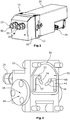
- FIG. 2 the second housing part 16 is shown. Via the inlet 20, the fuel flows into a first connecting channel 28 which serves as an inlet and extends through the second housing part 16 as far as its end wall 30 delimiting the end face. In this wall 30 several more channels are milled.
- a first channel which leads into the radially inner region, serves as a first inlet channel 32 and opens into a first inlet opening 34, which is kidney-shaped and in one in the FIGS. 3 and 4 to be recognized displacement chamber 36 of the displacement counter 14 leads.
- a second inlet channel 38 is formed in the first housing part 12. According to FIG.
- a second section of the bypass line 42 corresponding to the first section extends from the measuring chamber 44 in the direction of the outlet 22 on the radially opposite side of the second housing part 16 from the side of a piston arranged in the measuring chamber 44, as opposed to the first section of the bypass line 42.
- the piston has the same specific gravity as the measuring fluid, so as the fuel, and is like the measuring chamber 44 cylindrically shaped; the measuring chamber 44 thus has an inner diameter which substantially corresponds to the outer diameter of the piston.
- first kidney-shaped outlet opening 46 which in turn opens into a first outlet channel 48, which is fluidically connected to the outlet 22 via a second connecting channel 50 extending through the second housing part 16.
- This serving as a drain connection channel 50 is also fluidly connected to a formed in the first housing part 12 and the connecting channel 50 opposite the second drain passage 52.
- an axial groove 54 is formed on the end wall 30, which surrounds the channels formed in the second housing part 16 and which serves to receive a seal, not shown, which bears against the first housing part 12 after assembly, so that a tight connection of the two housing parts 12, 16 is produced.
- the first housing part 12 is shown in a view of a contact surface 56, with which the first housing part 12 bears against the wall 30 of the second housing part 16 delimiting the displacement chamber 36 at the end.
- a receiving opening 58 is formed, in which a drive shaft 60 of the drive motor of the displacement counter 14 protrudes.
- a bushing 62 is used, which serves as a displacement chamber 36 and correspondingly serves as a drivable Verdrängerrad 64 serving inner gear and an outer gear 66 of the Verdränger prestigeers 14.
- the essentially pot-shaped bushing 62 has correspondingly on its rear side the displacement chamber 36 bounding wall 68 has a through hole 70 through which the drive shaft 60 projects into the displacement chamber 36.
- two grooves 74 are formed on the outer circumference, which serve as a section of the second inlet channel 38 and the second outlet channel 52 and the front side into the connecting channels 28, 50 and the first inlet channel 32 and the first outlet channel 48 of the second housing part sixteenth lead. These grooves 74 are closed radially by an inner wall 76 of the receiving opening 58. At the opposite side to the second housing part 16, the two grooves 74 each open into a transverse bore 78, which are formed in the rear-limiting wall 68 of the sleeve 62 and opposite to the respective groove 74 Ends in a second inlet opening 80 and a second outlet opening 82 to the displacement chamber 36 open.
- This second inlet opening 80 is kidney-shaped, wherein the second inlet opening 80 is arranged in mirror image to the first outlet opening 46 with respect to a cross section perpendicular to the axis of rotation of the gearwheels 64, 66 in mirror image to the frontal first inlet opening 34 and the second outlet opening 82.
- the bushing 62 is shown with the internal gear 64 serving as a drivable Verdrängerrad and radially mounted in the sleeve 62 outer gear 66.
- the kidney-shaped first and second inlet openings 34, 80 and the kidney-shaped first and second outlet openings 46, 82 extend with their outer peripheries so far in the direction of the radially delimiting outer wall 72 of the bushing 62, that they open as exactly as possible to tooth roots 84 of the external gear 66.
- fuel now passes via a high-pressure pump and one or more injection valves to the inlet 20 and continues to flow via the connecting channel 28 serving as an inlet to the two inlet channels 32, 38 and via the inlet openings 34, 80 into the displacement chamber 36 , which is thus filled both the front side and the back.
- the fuel exits the displacer chamber 36 again via the two outlet openings 46, 82 and flows via the drainage channels 48, 52 back to the drainage connection channel 50 to subsequently return the device via the outlet 22 leave.
- a pressure difference between the front and the back of the piston can arise, which leads to a deflection of the piston from its rest position. Accordingly, the deflection of the piston is a measure of the applied pressure difference.
- a displacement sensor is arranged, which is in operative connection with the piston and in which by the deflection of the piston, a dependent on the size of the deflection voltage is generated.
- This displacement sensor attached to the measuring chamber 44 is, in particular, a magnetoresistive sensor, by means of which the field strength of a magnet acting on it is converted into a voltage. As displacement sensors and light sensors can be used.
- the displacement sensor is connected to the evaluation and control unit 24, which receives the values of this displacement sensor and transmits corresponding control signals to the drive motor, which is possibly controlled such that the piston is always in a defined starting position.
- the rotary displacement meter 14 is thus driven in such a way that it constantly compensates for the pressure difference due to the injected fluid on the piston by means of delivery.
- a pressure sensor and a temperature sensor are further arranged, which continuously measure the pressures and temperatures occurring in this area and in turn the evaluation and control unit 24 to account for changes in density in the calculation can.
- the sequence of the measurements takes place in such a way that, in the calculation of a total flow to be determined in the evaluation and control unit 24, both a flow in the bypass line 42 and an actual flow resulting from the movement or position of the piston and the volume displaced therewith in the measuring chamber 44 Flow of the gear pump 14 in a predetermined time interval be considered and both flows are added together to determine the total flow.
- the determination of the flow rate at the piston takes place, for example, by the deflection of the piston being differentiated in the evaluation and control unit, which is connected to the displacement sensor, and then multiplied by the base area of the piston, so that a volume flow in the bypass line 42 in FIG this time interval results.
- the flow through the positive displacement counter 14 can either be determined from the determined control data or calculated via the rotational speed, if this is measured directly at the positive displacement counter 14 or at the drive motor, for example via optical encoders or magnetoresistive sensors.
- the cavitation load in the displacement chamber 36 and the displacement wheel 64 decreases markedly and the positive displacement counter 14 thus remains much longer lasting. This increases the accuracy of the measurement results, since each revolution of the displacement counter 14 must be assigned a volume flow, which would change in the course of operation in case of excessive wear due to additional cavities. Another advantage results from the interchangeability and free choice of material of the socket.
- the invention is not limited to the embodiment described, but various modifications are possible within the scope of the main claim.
- the arrangement of the channels and the housing divisions can be changed as well as the design of Verdrängeriquesers, which can be performed for example as a double gear pump or vane pump.
- the positive displacement meter instead of the sleeve, can be arranged directly in the recess or the socket can be designed without its own rear wall.
- an improved distribution of the inflow into the displacement chamber is already achieved in that only two inlet openings are formed on the two axially delimiting sides of the displacement chamber.
Claims (12)
- Dispositif de mesure des processus d'écoulement de fluides comprenant
une entrée (20),
une sortie (22),
un compteur de déplacement pouvant être entraîné (14), qui est disposé dans un carter (10) dans lequel est formée une chambre de déplacement (36), dans laquelle au moins une roue à déplacement (64) entraînée est disposée de manière rotative, la chambre de déplacement (36) étant reliée de manière fluidique à l'entrée (20) par un premier canal d'entrée (32) et à la sortie (22) par un premier canal de sortie (48),
une conduite de dérivation (42) par laquelle le compteur de déplacement positif (14) peut être contourné,
un capteur de différence de pression (189, qui est disposé dans la conduite de dérivation (42)
et une unité d'évaluation et de commande (24) par l'intermédiaire de laquelle le compteur de déplacement (14) entraînable peut être réglé en fonction de la différence de pression présente au capteur de différence de pression (18),
caractérisé en ce que
le premier canal d'entrée (32) s'ouvre, par une première ouverture d'entrée (34), dans la chambre de déplacement (36), côté de front, et un second canal d'entrée (38) relié fluidiquement à l'entrée (20) s'ouvre, côté arrière, dans la chambre de déplacement (36) par une deuxième ouverture d'entrée (80).. - Dispositif de mesure des processus d'écoulement de fluides comprenant selon la revendication 1, caractérisé en ce que le premier canal de sortie (48) s'ouvre dans la chambre de déplacement (36) par une première ouverture de sortie (46), et un deuxième canal de sortie (52) s'ouvre à l'arrière dans la chambre de déplacement (36) par un deuxième orifice de sortie (82).
- Dispositif de mesure de processus d'écoulement de fluides selon l'une des revendications 1 ou 2, caractérisé en ce que le carter (10) est conçu en deux parties, la chambre de déplacement (36) étant disposée dans une première partie (12) du carter, la chambre étant fermée par une deuxième partie de carter, dans laquelle sont agencées l'ouverture d'entrée (34), côté de front, et/ ou, si référé à la revendication 2, l'orifice de sortie (46), et dans laquelle est disposée une chambre de mesure (44) du capteur de différence de pression (18).
- Dispositif de mesure de processus d'écoulement de fluides selon l'une des revendications précédentes, caractérisé en ce que les ouvertures d'entrée (34, 80) et/ou, si référé à la revendication 2, les ouvertures de sortie (46, 82) sont formées en forme de rein, côtés de front et d'arrière du carter (10) délimitant la chambre de déplacement (36).
- Dispositif pour mesurer des processus d'écoulement de fluides selon la revendication 4, caractérisé en ce que le compteur de déplacement positif (14) est réalisé comme une pompe à engrenages, et que les ouvertures d'entrée (34, 80) et/ou de sortie (46, 82) en forme de rein s'étendent radialement vers l'extérieur jusqu'aux fonds des dents (84) du roue de déplacement (64).
- Dispositif pour mesurer des processus d'écoulement de fluides selon l'une des revendications précédentes, caractérisé en ce que l'ouverture d'entrée (34) et/ou, si référée à la revendication 2, l'ouverture de sortie (46) sont formées en face de la chambre de déplacement (36) à l'image de l'ouverture d'entrée (80) et/ou de l'ouverture de sortie (82) à l'arrière de la chambre de déplacement (36).
- Dispositif de mesure de flux de fluides selon l'une des revendications précédentes, caractérisé en ce que le premier canal d'entrée (32) et le deuxième canal d'entrée (38) et/ou le premier canal de sortie (48) et le deuxième canal de sortie (52) sont en liaison fluidique par des canaux de liaison (28, 50) disposés dans le carter (10) et les deux canaux d'entrée (32, 38) et/ou les deux canaux d'écoulement (48, 52) sont, par les canaux de liaison (28, 50), en liaison fluidique avec l'entrée (20) et/ou la sortie (22) commune formées sur le carter (10).
- Dispositif de mesure de processus d'écoulement de fluides selon l'une des revendications précédentes, caractérisé en ce que les ouvertures d'entrée (34, 80) et/ou, si référée à la revendication 2, les ouvertures de sortie (46, 82) sont usinées dans les parois (30, 68) délimitent la chambre de déplacement (36) à l'avant et à l'arrière.
- Dispositif de mesure de processus d'écoulement de fluides selon l'une des revendications précédentes 3 à 8, caractérisé en ce que dans la première partie de carter (12), une douille (62) est disposée, qui forme la chambre de déplacement (36) et qui est insérée dans une ouverture de logement correspondante (58) de la première partie de carter (12).
- Dispositif de dosage de débit de fluide selon la revendication 9, caractérisé en ce que la douille (62) comprend la paroi (68) délimitant la chambre de déplacement (36) à l'arrière, dans laquelle la deuxième ouverture d'entrée (80) et/ou la deuxième ouverture de sortie (82) sont formées.
- Dispositif de mesure de processus d'écoulement de fluides selon l'une des revendications 9 ou 10, caractérisé en ce que le deuxième canal d'entrée (38) et le deuxième canal de sortie (52) sont formés au moins partiellement dans la paroi (68) délimitant, côté arrière, la chambre de déplacement (36) et à la paroi extérieure (72) délimitant radialement de la douille (62).
- Dispositif pour mesurer des processus d'écoulement de fluides selon la revendication 11, caractérisé en ce que sur le côté extérieur radial de la paroi extérieure délimitant radialement (72) de la douille (62), des rainures (74) sont formées, qui forment une section du deuxième canal d'entrée (38) et du deuxième canal de sortie (52), qui sont fermées radialement vers l'extérieur par la première partie de carter (12).
Applications Claiming Priority (2)
| Application Number | Priority Date | Filing Date | Title |
|---|---|---|---|
| ATA602/2015A AT517818B1 (de) | 2015-09-15 | 2015-09-15 | Zweiseitig anströmbare Vorrichtung zur Messung von Durchflussvorgängen von Fluiden |
| PCT/EP2016/071769 WO2017046209A1 (fr) | 2015-09-15 | 2016-09-15 | Dispositif d'écoulement fluidique bidirectionnel destiné à mesurer des processus d'écoulement de fluides |
Publications (2)
| Publication Number | Publication Date |
|---|---|
| EP3350444A1 EP3350444A1 (fr) | 2018-07-25 |
| EP3350444B1 true EP3350444B1 (fr) | 2019-10-30 |
Family
ID=56926206
Family Applications (1)
| Application Number | Title | Priority Date | Filing Date |
|---|---|---|---|
| EP16765993.7A Active EP3350444B1 (fr) | 2015-09-15 | 2016-09-15 | Dispositif d'écoulement fluidique bidirectionnel destiné à mesurer des processus d'écoulement de fluides |
Country Status (7)
| Country | Link |
|---|---|
| US (1) | US10634138B2 (fr) |
| EP (1) | EP3350444B1 (fr) |
| JP (1) | JP6526912B2 (fr) |
| KR (1) | KR102033864B1 (fr) |
| CN (1) | CN108138764B (fr) |
| AT (1) | AT517818B1 (fr) |
| WO (1) | WO2017046209A1 (fr) |
Family Cites Families (14)
| Publication number | Priority date | Publication date | Assignee | Title |
|---|---|---|---|---|
| US3273502A (en) | 1964-02-24 | 1966-09-20 | Stewart Warner Corp | Pumping and metering device |
| DE1798080C2 (de) | 1968-08-19 | 1974-05-16 | Pierburg Luftfahrtgeraete Union Gmbh, 4040 Neuss | Elektronisch gesteuertes Durchflußmeß- und Dosiergerät |
| US4255093A (en) * | 1979-03-23 | 1981-03-10 | Sundstrand Corporation | Combined lift and metering pump |
| GB2185785B (en) * | 1986-01-25 | 1989-11-01 | Ford Motor Co | Liquid flow meter |
| JPH0243480U (fr) * | 1988-09-19 | 1990-03-26 | ||
| DE10331228B3 (de) | 2003-07-10 | 2005-01-27 | Pierburg Instruments Gmbh | Vorrichtung zur Messung von zeitlich aufgelösten volumetrischen Durchflußvorgängen |
| EP1568973A1 (fr) | 2004-02-26 | 2005-08-31 | Signal Lux MDS S.r.l. | Débitmètre thermique pour fluides |
| JP2008115773A (ja) * | 2006-11-06 | 2008-05-22 | Aisin Seiki Co Ltd | オイルポンプ |
| JP4183096B2 (ja) * | 2007-02-05 | 2008-11-19 | 株式会社オーバル | サーボ型容積流量計における被測定流体の流れと差圧検出とに係る経路構造 |
| JP5562170B2 (ja) * | 2010-08-09 | 2014-07-30 | 株式会社ジェイテクト | 車両用内接歯車型オイルポンプ |
| AT512027B1 (de) * | 2013-01-30 | 2014-04-15 | Avl List Gmbh | Durchflussmessgerät |
| AT512619B1 (de) * | 2013-06-26 | 2015-02-15 | Avl List Gmbh | Durchflussmessgerät |
| GB201312558D0 (en) | 2013-07-12 | 2013-08-28 | Gill Res And Dev Ltd | An ultrasonic flowmeter |
| AT517819B1 (de) * | 2015-09-15 | 2017-08-15 | Avl List Gmbh | Spülbare Vorrichtung zur Messung von Durchflussvorgängen von Fluiden |
-
2015
- 2015-09-15 AT ATA602/2015A patent/AT517818B1/de active
-
2016
- 2016-09-15 WO PCT/EP2016/071769 patent/WO2017046209A1/fr active Application Filing
- 2016-09-15 EP EP16765993.7A patent/EP3350444B1/fr active Active
- 2016-09-15 KR KR1020187004032A patent/KR102033864B1/ko active IP Right Grant
- 2016-09-15 JP JP2018513588A patent/JP6526912B2/ja active Active
- 2016-09-15 CN CN201680049975.0A patent/CN108138764B/zh active Active
- 2016-09-15 US US15/759,522 patent/US10634138B2/en active Active
Non-Patent Citations (1)
| Title |
|---|
| None * |
Also Published As
| Publication number | Publication date |
|---|---|
| CN108138764A (zh) | 2018-06-08 |
| KR102033864B1 (ko) | 2019-10-17 |
| US20190145409A1 (en) | 2019-05-16 |
| JP6526912B2 (ja) | 2019-06-05 |
| KR20180043259A (ko) | 2018-04-27 |
| AT517818A1 (de) | 2017-04-15 |
| US10634138B2 (en) | 2020-04-28 |
| WO2017046209A1 (fr) | 2017-03-23 |
| CN108138764B (zh) | 2019-11-19 |
| AT517818B1 (de) | 2017-08-15 |
| JP2018529097A (ja) | 2018-10-04 |
| EP3350444A1 (fr) | 2018-07-25 |
Similar Documents
| Publication | Publication Date | Title |
|---|---|---|
| EP0572621B1 (fr) | Dispositif de mesure de la quantite de liquide dans des pompes a essence de stations-service de vehicules a moteur | |
| AT516622B1 (de) | System zur Messung von zeitlich aufgelösten Durchflussvorgängen von Fluiden | |
| EP3015829A1 (fr) | Debitmetre helicoïdal | |
| EP3350446B1 (fr) | Dispositif pouvant être purgé servant à mesurer des processus d'écoulement de fluides | |
| EP2562463B1 (fr) | Unité de pompe à lubrifiant | |
| AT517817B1 (de) | Vorrichtung mit Spalttopfmotor zur Messung von Durchflussvorgängen von Messfluiden | |
| EP3350444B1 (fr) | Dispositif d'écoulement fluidique bidirectionnel destiné à mesurer des processus d'écoulement de fluides | |
| EP2235473B1 (fr) | Dispositif et procédé de mesure géométrique d'une pièce | |
| DE102014212255A1 (de) | Außenzahnradmaschine mit Lagerkörpern, die geradlinig gleitbeweglich aneinander abgestützt sind | |
| WO2017046199A1 (fr) | Dispositif pourvu d'un moteur à chemise d'entrefer, servant à mesurer des processus d'écoulement de fluides | |
| DE1948622C3 (de) | Woltmann-Flüssigkeitszähler | |
| DE102010063547A1 (de) | Pumpe, Verdichter oder Motor mehrstufig oder mehrflutig | |
| EP0187941B1 (fr) | Dispositif pour le calibrage de pompes d'injection | |
| DE2826285C2 (de) | Hydrostatisches Drehmomentmeßgerät für drehende Wellen | |
| DE10228025B3 (de) | Volumenstromdosiereinrichtung | |
| DE102018204086A1 (de) | Zahnradfluidmaschine | |
| DE102018212497A1 (de) | Fluidfördereinrichtung | |
| EP1180600A2 (fr) | Procédé de mesure et de contrôle d'un débit instantané d'une pompe centrifuge | |
| DE102007043128B4 (de) | Axialer Mehrstrahlflügelradvolumenmesser | |
| DE102011082578A1 (de) | Zahnradpumpe | |
| EP3350445A1 (fr) | Dispositif pourvu d'un moteur à chemise d'entrefer, servant à mesurer des processus d'écoulement de fluides | |
| AT517711B1 (de) | Druckdifferenzaufnehmer für ein Durchflussmessgerät sowie Durchflussmessgerät | |
| DE102007008265A1 (de) | Gerotorpumpe | |
| WO2016180570A1 (fr) | Pompe volumétrique, procédé de fonctionnement d'une pompe volumétrique, système de direction et mécanisme | |
| DE3318166A1 (de) | Vorrichtung zur anzeige eines verdrehwinkels von lauf- und/oder leitschaufeln an stroemungsmaschinen |
Legal Events
| Date | Code | Title | Description |
|---|---|---|---|
| STAA | Information on the status of an ep patent application or granted ep patent |
Free format text: STATUS: THE INTERNATIONAL PUBLICATION HAS BEEN MADE |
|
| PUAI | Public reference made under article 153(3) epc to a published international application that has entered the european phase |
Free format text: ORIGINAL CODE: 0009012 |
|
| STAA | Information on the status of an ep patent application or granted ep patent |
Free format text: STATUS: REQUEST FOR EXAMINATION WAS MADE |
|
| 17P | Request for examination filed |
Effective date: 20180404 |
|
| AK | Designated contracting states |
Kind code of ref document: A1 Designated state(s): AL AT BE BG CH CY CZ DE DK EE ES FI FR GB GR HR HU IE IS IT LI LT LU LV MC MK MT NL NO PL PT RO RS SE SI SK SM TR |
|
| AX | Request for extension of the european patent |
Extension state: BA ME |
|
| DAV | Request for validation of the european patent (deleted) | ||
| DAX | Request for extension of the european patent (deleted) | ||
| GRAP | Despatch of communication of intention to grant a patent |
Free format text: ORIGINAL CODE: EPIDOSNIGR1 |
|
| STAA | Information on the status of an ep patent application or granted ep patent |
Free format text: STATUS: GRANT OF PATENT IS INTENDED |
|
| INTG | Intention to grant announced |
Effective date: 20190524 |
|
| GRAS | Grant fee paid |
Free format text: ORIGINAL CODE: EPIDOSNIGR3 |
|
| GRAA | (expected) grant |
Free format text: ORIGINAL CODE: 0009210 |
|
| STAA | Information on the status of an ep patent application or granted ep patent |
Free format text: STATUS: THE PATENT HAS BEEN GRANTED |
|
| AK | Designated contracting states |
Kind code of ref document: B1 Designated state(s): AL AT BE BG CH CY CZ DE DK EE ES FI FR GB GR HR HU IE IS IT LI LT LU LV MC MK MT NL NO PL PT RO RS SE SI SK SM TR |
|
| REG | Reference to a national code |
Ref country code: GB Ref legal event code: FG4D Free format text: NOT ENGLISH |
|
| REG | Reference to a national code |
Ref country code: CH Ref legal event code: EP |
|
| REG | Reference to a national code |
Ref country code: AT Ref legal event code: REF Ref document number: 1196434 Country of ref document: AT Kind code of ref document: T Effective date: 20191115 |
|
| REG | Reference to a national code |
Ref country code: DE Ref legal event code: R096 Ref document number: 502016007341 Country of ref document: DE |
|
| REG | Reference to a national code |
Ref country code: IE Ref legal event code: FG4D Free format text: LANGUAGE OF EP DOCUMENT: GERMAN |
|
| REG | Reference to a national code |
Ref country code: DE Ref legal event code: R082 Ref document number: 502016007341 Country of ref document: DE Representative=s name: STOLMAR & PARTNER PATENTANWAELTE PARTG MBB, DE Ref country code: DE Ref legal event code: R082 Ref document number: 502016007341 Country of ref document: DE Representative=s name: TERPATENT PATENTANWAELTE TER SMITTEN EBERLEIN-, DE |
|
| REG | Reference to a national code |
Ref country code: LT Ref legal event code: MG4D |
|
| PG25 | Lapsed in a contracting state [announced via postgrant information from national office to epo] |
Ref country code: LT Free format text: LAPSE BECAUSE OF FAILURE TO SUBMIT A TRANSLATION OF THE DESCRIPTION OR TO PAY THE FEE WITHIN THE PRESCRIBED TIME-LIMIT Effective date: 20191030 Ref country code: GR Free format text: LAPSE BECAUSE OF FAILURE TO SUBMIT A TRANSLATION OF THE DESCRIPTION OR TO PAY THE FEE WITHIN THE PRESCRIBED TIME-LIMIT Effective date: 20200131 Ref country code: PL Free format text: LAPSE BECAUSE OF FAILURE TO SUBMIT A TRANSLATION OF THE DESCRIPTION OR TO PAY THE FEE WITHIN THE PRESCRIBED TIME-LIMIT Effective date: 20191030 Ref country code: BG Free format text: LAPSE BECAUSE OF FAILURE TO SUBMIT A TRANSLATION OF THE DESCRIPTION OR TO PAY THE FEE WITHIN THE PRESCRIBED TIME-LIMIT Effective date: 20200130 Ref country code: NL Free format text: LAPSE BECAUSE OF FAILURE TO SUBMIT A TRANSLATION OF THE DESCRIPTION OR TO PAY THE FEE WITHIN THE PRESCRIBED TIME-LIMIT Effective date: 20191030 Ref country code: PT Free format text: LAPSE BECAUSE OF FAILURE TO SUBMIT A TRANSLATION OF THE DESCRIPTION OR TO PAY THE FEE WITHIN THE PRESCRIBED TIME-LIMIT Effective date: 20200302 Ref country code: FI Free format text: LAPSE BECAUSE OF FAILURE TO SUBMIT A TRANSLATION OF THE DESCRIPTION OR TO PAY THE FEE WITHIN THE PRESCRIBED TIME-LIMIT Effective date: 20191030 Ref country code: NO Free format text: LAPSE BECAUSE OF FAILURE TO SUBMIT A TRANSLATION OF THE DESCRIPTION OR TO PAY THE FEE WITHIN THE PRESCRIBED TIME-LIMIT Effective date: 20200130 Ref country code: SE Free format text: LAPSE BECAUSE OF FAILURE TO SUBMIT A TRANSLATION OF THE DESCRIPTION OR TO PAY THE FEE WITHIN THE PRESCRIBED TIME-LIMIT Effective date: 20191030 Ref country code: LV Free format text: LAPSE BECAUSE OF FAILURE TO SUBMIT A TRANSLATION OF THE DESCRIPTION OR TO PAY THE FEE WITHIN THE PRESCRIBED TIME-LIMIT Effective date: 20191030 |
|
| REG | Reference to a national code |
Ref country code: NL Ref legal event code: MP Effective date: 20191030 |
|
| PG25 | Lapsed in a contracting state [announced via postgrant information from national office to epo] |
Ref country code: IS Free format text: LAPSE BECAUSE OF FAILURE TO SUBMIT A TRANSLATION OF THE DESCRIPTION OR TO PAY THE FEE WITHIN THE PRESCRIBED TIME-LIMIT Effective date: 20200229 Ref country code: HR Free format text: LAPSE BECAUSE OF FAILURE TO SUBMIT A TRANSLATION OF THE DESCRIPTION OR TO PAY THE FEE WITHIN THE PRESCRIBED TIME-LIMIT Effective date: 20191030 Ref country code: RS Free format text: LAPSE BECAUSE OF FAILURE TO SUBMIT A TRANSLATION OF THE DESCRIPTION OR TO PAY THE FEE WITHIN THE PRESCRIBED TIME-LIMIT Effective date: 20191030 |
|
| PG25 | Lapsed in a contracting state [announced via postgrant information from national office to epo] |
Ref country code: AL Free format text: LAPSE BECAUSE OF FAILURE TO SUBMIT A TRANSLATION OF THE DESCRIPTION OR TO PAY THE FEE WITHIN THE PRESCRIBED TIME-LIMIT Effective date: 20191030 |
|
| PG25 | Lapsed in a contracting state [announced via postgrant information from national office to epo] |
Ref country code: ES Free format text: LAPSE BECAUSE OF FAILURE TO SUBMIT A TRANSLATION OF THE DESCRIPTION OR TO PAY THE FEE WITHIN THE PRESCRIBED TIME-LIMIT Effective date: 20191030 Ref country code: CZ Free format text: LAPSE BECAUSE OF FAILURE TO SUBMIT A TRANSLATION OF THE DESCRIPTION OR TO PAY THE FEE WITHIN THE PRESCRIBED TIME-LIMIT Effective date: 20191030 Ref country code: RO Free format text: LAPSE BECAUSE OF FAILURE TO SUBMIT A TRANSLATION OF THE DESCRIPTION OR TO PAY THE FEE WITHIN THE PRESCRIBED TIME-LIMIT Effective date: 20191030 Ref country code: DK Free format text: LAPSE BECAUSE OF FAILURE TO SUBMIT A TRANSLATION OF THE DESCRIPTION OR TO PAY THE FEE WITHIN THE PRESCRIBED TIME-LIMIT Effective date: 20191030 Ref country code: EE Free format text: LAPSE BECAUSE OF FAILURE TO SUBMIT A TRANSLATION OF THE DESCRIPTION OR TO PAY THE FEE WITHIN THE PRESCRIBED TIME-LIMIT Effective date: 20191030 |
|
| REG | Reference to a national code |
Ref country code: DE Ref legal event code: R097 Ref document number: 502016007341 Country of ref document: DE |
|
| PG25 | Lapsed in a contracting state [announced via postgrant information from national office to epo] |
Ref country code: SK Free format text: LAPSE BECAUSE OF FAILURE TO SUBMIT A TRANSLATION OF THE DESCRIPTION OR TO PAY THE FEE WITHIN THE PRESCRIBED TIME-LIMIT Effective date: 20191030 Ref country code: IT Free format text: LAPSE BECAUSE OF FAILURE TO SUBMIT A TRANSLATION OF THE DESCRIPTION OR TO PAY THE FEE WITHIN THE PRESCRIBED TIME-LIMIT Effective date: 20191030 Ref country code: SM Free format text: LAPSE BECAUSE OF FAILURE TO SUBMIT A TRANSLATION OF THE DESCRIPTION OR TO PAY THE FEE WITHIN THE PRESCRIBED TIME-LIMIT Effective date: 20191030 |
|
| PLBE | No opposition filed within time limit |
Free format text: ORIGINAL CODE: 0009261 |
|
| STAA | Information on the status of an ep patent application or granted ep patent |
Free format text: STATUS: NO OPPOSITION FILED WITHIN TIME LIMIT |
|
| 26N | No opposition filed |
Effective date: 20200731 |
|
| PG25 | Lapsed in a contracting state [announced via postgrant information from national office to epo] |
Ref country code: SI Free format text: LAPSE BECAUSE OF FAILURE TO SUBMIT A TRANSLATION OF THE DESCRIPTION OR TO PAY THE FEE WITHIN THE PRESCRIBED TIME-LIMIT Effective date: 20191030 |
|
| REG | Reference to a national code |
Ref country code: CH Ref legal event code: PL |
|
| REG | Reference to a national code |
Ref country code: BE Ref legal event code: MM Effective date: 20200930 |
|
| PG25 | Lapsed in a contracting state [announced via postgrant information from national office to epo] |
Ref country code: LU Free format text: LAPSE BECAUSE OF NON-PAYMENT OF DUE FEES Effective date: 20200915 |
|
| PG25 | Lapsed in a contracting state [announced via postgrant information from national office to epo] |
Ref country code: FR Free format text: LAPSE BECAUSE OF NON-PAYMENT OF DUE FEES Effective date: 20200930 |
|
| PG25 | Lapsed in a contracting state [announced via postgrant information from national office to epo] |
Ref country code: IE Free format text: LAPSE BECAUSE OF NON-PAYMENT OF DUE FEES Effective date: 20200915 Ref country code: LI Free format text: LAPSE BECAUSE OF NON-PAYMENT OF DUE FEES Effective date: 20200930 Ref country code: BE Free format text: LAPSE BECAUSE OF NON-PAYMENT OF DUE FEES Effective date: 20200930 Ref country code: CH Free format text: LAPSE BECAUSE OF NON-PAYMENT OF DUE FEES Effective date: 20200930 |
|
| PGFP | Annual fee paid to national office [announced via postgrant information from national office to epo] |
Ref country code: GB Payment date: 20210923 Year of fee payment: 6 |
|
| PG25 | Lapsed in a contracting state [announced via postgrant information from national office to epo] |
Ref country code: TR Free format text: LAPSE BECAUSE OF FAILURE TO SUBMIT A TRANSLATION OF THE DESCRIPTION OR TO PAY THE FEE WITHIN THE PRESCRIBED TIME-LIMIT Effective date: 20191030 Ref country code: MT Free format text: LAPSE BECAUSE OF FAILURE TO SUBMIT A TRANSLATION OF THE DESCRIPTION OR TO PAY THE FEE WITHIN THE PRESCRIBED TIME-LIMIT Effective date: 20191030 Ref country code: CY Free format text: LAPSE BECAUSE OF FAILURE TO SUBMIT A TRANSLATION OF THE DESCRIPTION OR TO PAY THE FEE WITHIN THE PRESCRIBED TIME-LIMIT Effective date: 20191030 |
|
| PG25 | Lapsed in a contracting state [announced via postgrant information from national office to epo] |
Ref country code: MK Free format text: LAPSE BECAUSE OF FAILURE TO SUBMIT A TRANSLATION OF THE DESCRIPTION OR TO PAY THE FEE WITHIN THE PRESCRIBED TIME-LIMIT Effective date: 20191030 Ref country code: MC Free format text: LAPSE BECAUSE OF FAILURE TO SUBMIT A TRANSLATION OF THE DESCRIPTION OR TO PAY THE FEE WITHIN THE PRESCRIBED TIME-LIMIT Effective date: 20191030 |
|
| REG | Reference to a national code |
Ref country code: AT Ref legal event code: MM01 Ref document number: 1196434 Country of ref document: AT Kind code of ref document: T Effective date: 20210915 |
|
| PG25 | Lapsed in a contracting state [announced via postgrant information from national office to epo] |
Ref country code: AT Free format text: LAPSE BECAUSE OF NON-PAYMENT OF DUE FEES Effective date: 20210915 |
|
| GBPC | Gb: european patent ceased through non-payment of renewal fee |
Effective date: 20220915 |
|
| P01 | Opt-out of the competence of the unified patent court (upc) registered |
Effective date: 20230502 |
|
| PG25 | Lapsed in a contracting state [announced via postgrant information from national office to epo] |
Ref country code: GB Free format text: LAPSE BECAUSE OF NON-PAYMENT OF DUE FEES Effective date: 20220915 |
|
| PGFP | Annual fee paid to national office [announced via postgrant information from national office to epo] |
Ref country code: DE Payment date: 20230919 Year of fee payment: 8 |
|
| REG | Reference to a national code |
Ref country code: DE Ref legal event code: R082 Ref document number: 502016007341 Country of ref document: DE Representative=s name: STOLMAR & PARTNER PATENTANWAELTE PARTG MBB, DE |