EP3350444B1 - Bidirectionally flow-impinged device for measuring flow processes of fluids - Google Patents
Bidirectionally flow-impinged device for measuring flow processes of fluids Download PDFInfo
- Publication number
- EP3350444B1 EP3350444B1 EP16765993.7A EP16765993A EP3350444B1 EP 3350444 B1 EP3350444 B1 EP 3350444B1 EP 16765993 A EP16765993 A EP 16765993A EP 3350444 B1 EP3350444 B1 EP 3350444B1
- Authority
- EP
- European Patent Office
- Prior art keywords
- positive displacement
- fluids
- inlet
- displacement chamber
- outlet
- Prior art date
- Legal status (The legal status is an assumption and is not a legal conclusion. Google has not performed a legal analysis and makes no representation as to the accuracy of the status listed.)
- Active
Links
- 239000012530 fluid Substances 0.000 title claims description 23
- 238000000034 method Methods 0.000 title claims description 22
- 230000008569 process Effects 0.000 title claims description 22
- 238000006073 displacement reaction Methods 0.000 claims description 80
- 238000011156 evaluation Methods 0.000 claims description 8
- 239000000446 fuel Substances 0.000 description 9
- 238000002347 injection Methods 0.000 description 7
- 239000007924 injection Substances 0.000 description 7
- 238000005259 measurement Methods 0.000 description 7
- 238000004519 manufacturing process Methods 0.000 description 5
- 239000000463 material Substances 0.000 description 3
- 230000003287 optical effect Effects 0.000 description 3
- 230000008901 benefit Effects 0.000 description 2
- 230000008859 change Effects 0.000 description 2
- 230000007423 decrease Effects 0.000 description 2
- 238000011161 development Methods 0.000 description 2
- 230000018109 developmental process Effects 0.000 description 2
- 230000004323 axial length Effects 0.000 description 1
- 230000015572 biosynthetic process Effects 0.000 description 1
- 238000002485 combustion reaction Methods 0.000 description 1
- 230000001419 dependent effect Effects 0.000 description 1
- 238000013461 design Methods 0.000 description 1
- 230000005484 gravity Effects 0.000 description 1
- 230000002045 lasting effect Effects 0.000 description 1
- 238000003801 milling Methods 0.000 description 1
- 238000012986 modification Methods 0.000 description 1
- 230000004048 modification Effects 0.000 description 1
- 238000012545 processing Methods 0.000 description 1
- 230000000750 progressive effect Effects 0.000 description 1
- 230000002035 prolonged effect Effects 0.000 description 1
- 230000009467 reduction Effects 0.000 description 1
- 238000007789 sealing Methods 0.000 description 1
- 238000000926 separation method Methods 0.000 description 1
- 239000007787 solid Substances 0.000 description 1
Images

Classifications
-
- F—MECHANICAL ENGINEERING; LIGHTING; HEATING; WEAPONS; BLASTING
- F04—POSITIVE - DISPLACEMENT MACHINES FOR LIQUIDS; PUMPS FOR LIQUIDS OR ELASTIC FLUIDS
- F04C—ROTARY-PISTON, OR OSCILLATING-PISTON, POSITIVE-DISPLACEMENT MACHINES FOR LIQUIDS; ROTARY-PISTON, OR OSCILLATING-PISTON, POSITIVE-DISPLACEMENT PUMPS
- F04C15/00—Component parts, details or accessories of machines, pumps or pumping installations, not provided for in groups F04C2/00 - F04C14/00
- F04C15/06—Arrangements for admission or discharge of the working fluid, e.g. constructional features of the inlet or outlet
-
- F—MECHANICAL ENGINEERING; LIGHTING; HEATING; WEAPONS; BLASTING
- F04—POSITIVE - DISPLACEMENT MACHINES FOR LIQUIDS; PUMPS FOR LIQUIDS OR ELASTIC FLUIDS
- F04C—ROTARY-PISTON, OR OSCILLATING-PISTON, POSITIVE-DISPLACEMENT MACHINES FOR LIQUIDS; ROTARY-PISTON, OR OSCILLATING-PISTON, POSITIVE-DISPLACEMENT PUMPS
- F04C2/00—Rotary-piston machines or pumps
- F04C2/08—Rotary-piston machines or pumps of intermeshing-engagement type, i.e. with engagement of co-operating members similar to that of toothed gearing
- F04C2/10—Rotary-piston machines or pumps of intermeshing-engagement type, i.e. with engagement of co-operating members similar to that of toothed gearing of internal-axis type with the outer member having more teeth or tooth-equivalents, e.g. rollers, than the inner member
-
- F—MECHANICAL ENGINEERING; LIGHTING; HEATING; WEAPONS; BLASTING
- F04—POSITIVE - DISPLACEMENT MACHINES FOR LIQUIDS; PUMPS FOR LIQUIDS OR ELASTIC FLUIDS
- F04C—ROTARY-PISTON, OR OSCILLATING-PISTON, POSITIVE-DISPLACEMENT MACHINES FOR LIQUIDS; ROTARY-PISTON, OR OSCILLATING-PISTON, POSITIVE-DISPLACEMENT PUMPS
- F04C2/00—Rotary-piston machines or pumps
- F04C2/30—Rotary-piston machines or pumps having the characteristics covered by two or more groups F04C2/02, F04C2/08, F04C2/22, F04C2/24 or having the characteristics covered by one of these groups together with some other type of movement between co-operating members
- F04C2/34—Rotary-piston machines or pumps having the characteristics covered by two or more groups F04C2/02, F04C2/08, F04C2/22, F04C2/24 or having the characteristics covered by one of these groups together with some other type of movement between co-operating members having the movement defined in groups F04C2/08 or F04C2/22 and relative reciprocation between the co-operating members
- F04C2/344—Rotary-piston machines or pumps having the characteristics covered by two or more groups F04C2/02, F04C2/08, F04C2/22, F04C2/24 or having the characteristics covered by one of these groups together with some other type of movement between co-operating members having the movement defined in groups F04C2/08 or F04C2/22 and relative reciprocation between the co-operating members with vanes reciprocating with respect to the inner member
-
- G—PHYSICS
- G01—MEASURING; TESTING
- G01F—MEASURING VOLUME, VOLUME FLOW, MASS FLOW OR LIQUID LEVEL; METERING BY VOLUME
- G01F15/00—Details of, or accessories for, apparatus of groups G01F1/00 - G01F13/00 insofar as such details or appliances are not adapted to particular types of such apparatus
- G01F15/02—Compensating or correcting for variations in pressure, density or temperature
- G01F15/026—Compensating or correcting for variations in pressure, density or temperature using means to maintain zero differential pressure across the motor
-
- G—PHYSICS
- G01—MEASURING; TESTING
- G01F—MEASURING VOLUME, VOLUME FLOW, MASS FLOW OR LIQUID LEVEL; METERING BY VOLUME
- G01F3/00—Measuring the volume flow of fluids or fluent solid material wherein the fluid passes through the meter in successive and more or less isolated quantities, the meter being driven by the flow
- G01F3/02—Measuring the volume flow of fluids or fluent solid material wherein the fluid passes through the meter in successive and more or less isolated quantities, the meter being driven by the flow with measuring chambers which expand or contract during measurement
- G01F3/04—Measuring the volume flow of fluids or fluent solid material wherein the fluid passes through the meter in successive and more or less isolated quantities, the meter being driven by the flow with measuring chambers which expand or contract during measurement having rigid movable walls
- G01F3/06—Measuring the volume flow of fluids or fluent solid material wherein the fluid passes through the meter in successive and more or less isolated quantities, the meter being driven by the flow with measuring chambers which expand or contract during measurement having rigid movable walls comprising members rotating in a fluid-tight or substantially fluid-tight manner in a housing
- G01F3/10—Geared or lobed impeller meters
-
- F—MECHANICAL ENGINEERING; LIGHTING; HEATING; WEAPONS; BLASTING
- F04—POSITIVE - DISPLACEMENT MACHINES FOR LIQUIDS; PUMPS FOR LIQUIDS OR ELASTIC FLUIDS
- F04C—ROTARY-PISTON, OR OSCILLATING-PISTON, POSITIVE-DISPLACEMENT MACHINES FOR LIQUIDS; ROTARY-PISTON, OR OSCILLATING-PISTON, POSITIVE-DISPLACEMENT PUMPS
- F04C2220/00—Application
- F04C2220/24—Application for metering throughflow
-
- F—MECHANICAL ENGINEERING; LIGHTING; HEATING; WEAPONS; BLASTING
- F04—POSITIVE - DISPLACEMENT MACHINES FOR LIQUIDS; PUMPS FOR LIQUIDS OR ELASTIC FLUIDS
- F04C—ROTARY-PISTON, OR OSCILLATING-PISTON, POSITIVE-DISPLACEMENT MACHINES FOR LIQUIDS; ROTARY-PISTON, OR OSCILLATING-PISTON, POSITIVE-DISPLACEMENT PUMPS
- F04C2270/00—Control; Monitoring or safety arrangements
- F04C2270/16—Wear
Definitions
- the invention relates to a device for measuring flow processes of fluids, an inlet, an outlet, a driven Verdrängergreater, which is arranged in a housing in which a displacement chamber is formed, in which at least one driven Verdrängerrad is rotatably arranged, wherein the displacement chamber via a first inlet channel to the inlet and via a first outlet channel to the outlet is fluidly connected, a bypass line through which the positive displacement counter is bypassed, a Druckdifferenzaufillon, which is arranged in the bypass line and an evaluation and control unit via which the drivable positive displacement counter in Dependence of the pressure difference sensor applied pressure difference is adjustable.
- Such devices have been known for many years and are used, for example, for injection quantity measurement in internal combustion engines.
- This electronically controlled flowmeter has a main conduit with an inlet and an outlet in which a rotary displacer in the form of a gear pump is arranged. Parallel to the main line runs a bypass line through which the rotary displacer is bypassed and in which a serving as Druckdifferenzaufêtender piston is arranged in a measuring chamber. To determine the flow rate, the deflection of the piston in the measuring chamber is measured by means of an optical sensor. The speed of the gear pump is continuously readjusted due to this signal via an evaluation and control unit, in such a way that the piston always returned to its original position, so that only small currents arise in the bypass line. From the measured via an encoder number of revolutions or partial revolutions of the gear pump and the known delivery volume of the gear pump in one revolution so the flow is calculated within a predetermined time interval.
- Such a constructed flow meter is also in the DE 103 31 228 B3 disclosed.
- the gear pump is set to a constant speed before each injection, so that subsequently the movement of the piston is measured and this deflection is used to determine the injection curves.
- a pressure sensor and a temperature sensor are arranged in the measuring chamber, the measured values of which are likewise fed to the arithmetic unit for calculating and correcting the injection quantity profiles.
- the occurring wear in the region of the displacement wheel opposite the inlet opening can be significantly reduced be achieved because a much more uniform load of the positive displacement wheel over its axial extent is achieved.
- the filling of the displacement chamber takes place correspondingly from both axial sides, whereby the number and intensity of the occurring pressure surges are reduced at the same solid surface of the displacer.
- the first drainage channel preferably opens into the displacement chamber via a first outlet opening and a second outlet channel opens into the displacement chamber via a second outlet opening on the rear side. Accordingly, a one-sided load of the positive displacement is prevented by the cavitation and counteracted according to a progressive Kavitationsfrrien by axially unilateral load on the pressure side of the positive displacement, in which there is a higher load due to the higher delivery pressure.
- the housing is designed in two parts, wherein in the first housing part, the displacement chamber is closed, which is closed by a second housing part in which the frontal inlet opening and / or outlet opening is arranged and in which a measuring chamber of the pressure difference sensor is arranged.
- the first housing part the displacement chamber is closed, which is closed by a second housing part in which the frontal inlet opening and / or outlet opening is arranged and in which a measuring chamber of the pressure difference sensor is arranged.
- the inlet openings and / or the outlet openings are kidney-shaped on the front side and on the rear side of the housing delimiting the displacement chamber, whereby a uniform filling of the pump chamber is achieved with a marked reduction in the pressure surges that occur.
- the positive displacement meter is designed as a gear pump and the kidney-shaped inlet openings and / or outlet openings extend radially outward to the tooth roots of the positive displacement, whereby pressure surges and resulting cavitation are additionally reduced and the filling of the displacement chamber is improved.
- the inlet opening and / or the outlet opening on the front side of the displacement chamber is designed mirror-inverted to the inlet opening and / or to the outlet opening on the rear side of the displacement chamber.
- a particularly simple supply line without further connections results when the first inlet channel and the second inlet channel and / or the first outlet channel and the second outlet channel are fluidically connected to each other via connection channels arranged in the housing and both inlet channels and / or both outlet channels fluidly with the common Housing formed inlet and / or outlet are connected.
- the number of external lines is thereby limited to a necessary minimum, whereby the assembly is simplified.
- the inlet openings and / or the outlet openings are milled into the displacement chamber on frontally and rearwardly delimiting walls. These walls are easily accessible, so that a cost-effective production of the openings by milling is possible.
- a bush is arranged in the first housing part, which forms the displacement chamber and which is inserted into a corresponding receiving opening of the first housing part.
- the second inlet channel and the second outlet channel are at least partially formed in the wall which bounds the displacement chamber on the rear side and on the radially delimiting outer wall of the socket.
- These channels can be made through easy-to-drill holes in the walls. Compared to a formation of the channels in the first housing part, the closing by additional plugs or the like is not required. Instead, a seal of these channels can be done by simple interposition of Axialdichtringes between the housing parts and the socket, whereby the assembly is significantly simplified.
- a particularly advantageous development of the invention results from the fact that grooves are formed on the radially outer side of the radially delimiting outer wall of the bush, which form a portion of the second inlet channel and the second outlet channel, which are closed radially outwardly by the first housing part. These grooves can be milled and form a particularly simple fluidic connection between the end face and the back of the displacement chamber for supplying this chamber with fluid on both sides.
- a device for measuring flow processes of fluids with which the occurring cavitation and the wear resulting from the cavitation can be significantly reduced due to the high pressure loads occurring on the positive displacement wheels.
- the device is easy to manufacture and assemble, so that incurred despite the increase in life no significant additional costs.
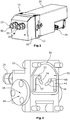
- FIG. 1 is the external view of a device according to the invention for the measurement of temporally resolved flow processes shown.
- the device according to the invention has a housing 10, which is manufactured in two parts, wherein in the first housing part 12, a positive displacement counter 14 is arranged and in the second housing part 16, a Druckdifferenzier choir 18, and an inlet 20 and an outlet 22 are formed.
- a drive motor of the displacement counter 14 and the evaluation and control unit 24 are within a hood 26th arranged, which is attached to the first housing part 12 as well as the second housing part 16.
- FIG. 2 the second housing part 16 is shown. Via the inlet 20, the fuel flows into a first connecting channel 28 which serves as an inlet and extends through the second housing part 16 as far as its end wall 30 delimiting the end face. In this wall 30 several more channels are milled.
- a first channel which leads into the radially inner region, serves as a first inlet channel 32 and opens into a first inlet opening 34, which is kidney-shaped and in one in the FIGS. 3 and 4 to be recognized displacement chamber 36 of the displacement counter 14 leads.
- a second inlet channel 38 is formed in the first housing part 12. According to FIG.
- a second section of the bypass line 42 corresponding to the first section extends from the measuring chamber 44 in the direction of the outlet 22 on the radially opposite side of the second housing part 16 from the side of a piston arranged in the measuring chamber 44, as opposed to the first section of the bypass line 42.
- the piston has the same specific gravity as the measuring fluid, so as the fuel, and is like the measuring chamber 44 cylindrically shaped; the measuring chamber 44 thus has an inner diameter which substantially corresponds to the outer diameter of the piston.
- first kidney-shaped outlet opening 46 which in turn opens into a first outlet channel 48, which is fluidically connected to the outlet 22 via a second connecting channel 50 extending through the second housing part 16.
- This serving as a drain connection channel 50 is also fluidly connected to a formed in the first housing part 12 and the connecting channel 50 opposite the second drain passage 52.
- an axial groove 54 is formed on the end wall 30, which surrounds the channels formed in the second housing part 16 and which serves to receive a seal, not shown, which bears against the first housing part 12 after assembly, so that a tight connection of the two housing parts 12, 16 is produced.
- the first housing part 12 is shown in a view of a contact surface 56, with which the first housing part 12 bears against the wall 30 of the second housing part 16 delimiting the displacement chamber 36 at the end.
- a receiving opening 58 is formed, in which a drive shaft 60 of the drive motor of the displacement counter 14 protrudes.
- a bushing 62 is used, which serves as a displacement chamber 36 and correspondingly serves as a drivable Verdrängerrad 64 serving inner gear and an outer gear 66 of the Verdränger prestigeers 14.
- the essentially pot-shaped bushing 62 has correspondingly on its rear side the displacement chamber 36 bounding wall 68 has a through hole 70 through which the drive shaft 60 projects into the displacement chamber 36.
- two grooves 74 are formed on the outer circumference, which serve as a section of the second inlet channel 38 and the second outlet channel 52 and the front side into the connecting channels 28, 50 and the first inlet channel 32 and the first outlet channel 48 of the second housing part sixteenth lead. These grooves 74 are closed radially by an inner wall 76 of the receiving opening 58. At the opposite side to the second housing part 16, the two grooves 74 each open into a transverse bore 78, which are formed in the rear-limiting wall 68 of the sleeve 62 and opposite to the respective groove 74 Ends in a second inlet opening 80 and a second outlet opening 82 to the displacement chamber 36 open.
- This second inlet opening 80 is kidney-shaped, wherein the second inlet opening 80 is arranged in mirror image to the first outlet opening 46 with respect to a cross section perpendicular to the axis of rotation of the gearwheels 64, 66 in mirror image to the frontal first inlet opening 34 and the second outlet opening 82.
- the bushing 62 is shown with the internal gear 64 serving as a drivable Verdrängerrad and radially mounted in the sleeve 62 outer gear 66.
- the kidney-shaped first and second inlet openings 34, 80 and the kidney-shaped first and second outlet openings 46, 82 extend with their outer peripheries so far in the direction of the radially delimiting outer wall 72 of the bushing 62, that they open as exactly as possible to tooth roots 84 of the external gear 66.
- fuel now passes via a high-pressure pump and one or more injection valves to the inlet 20 and continues to flow via the connecting channel 28 serving as an inlet to the two inlet channels 32, 38 and via the inlet openings 34, 80 into the displacement chamber 36 , which is thus filled both the front side and the back.
- the fuel exits the displacer chamber 36 again via the two outlet openings 46, 82 and flows via the drainage channels 48, 52 back to the drainage connection channel 50 to subsequently return the device via the outlet 22 leave.
- a pressure difference between the front and the back of the piston can arise, which leads to a deflection of the piston from its rest position. Accordingly, the deflection of the piston is a measure of the applied pressure difference.
- a displacement sensor is arranged, which is in operative connection with the piston and in which by the deflection of the piston, a dependent on the size of the deflection voltage is generated.
- This displacement sensor attached to the measuring chamber 44 is, in particular, a magnetoresistive sensor, by means of which the field strength of a magnet acting on it is converted into a voltage. As displacement sensors and light sensors can be used.
- the displacement sensor is connected to the evaluation and control unit 24, which receives the values of this displacement sensor and transmits corresponding control signals to the drive motor, which is possibly controlled such that the piston is always in a defined starting position.
- the rotary displacement meter 14 is thus driven in such a way that it constantly compensates for the pressure difference due to the injected fluid on the piston by means of delivery.
- a pressure sensor and a temperature sensor are further arranged, which continuously measure the pressures and temperatures occurring in this area and in turn the evaluation and control unit 24 to account for changes in density in the calculation can.
- the sequence of the measurements takes place in such a way that, in the calculation of a total flow to be determined in the evaluation and control unit 24, both a flow in the bypass line 42 and an actual flow resulting from the movement or position of the piston and the volume displaced therewith in the measuring chamber 44 Flow of the gear pump 14 in a predetermined time interval be considered and both flows are added together to determine the total flow.
- the determination of the flow rate at the piston takes place, for example, by the deflection of the piston being differentiated in the evaluation and control unit, which is connected to the displacement sensor, and then multiplied by the base area of the piston, so that a volume flow in the bypass line 42 in FIG this time interval results.
- the flow through the positive displacement counter 14 can either be determined from the determined control data or calculated via the rotational speed, if this is measured directly at the positive displacement counter 14 or at the drive motor, for example via optical encoders or magnetoresistive sensors.
- the cavitation load in the displacement chamber 36 and the displacement wheel 64 decreases markedly and the positive displacement counter 14 thus remains much longer lasting. This increases the accuracy of the measurement results, since each revolution of the displacement counter 14 must be assigned a volume flow, which would change in the course of operation in case of excessive wear due to additional cavities. Another advantage results from the interchangeability and free choice of material of the socket.
- the invention is not limited to the embodiment described, but various modifications are possible within the scope of the main claim.
- the arrangement of the channels and the housing divisions can be changed as well as the design of Verdrängeriquesers, which can be performed for example as a double gear pump or vane pump.
- the positive displacement meter instead of the sleeve, can be arranged directly in the recess or the socket can be designed without its own rear wall.
- an improved distribution of the inflow into the displacement chamber is already achieved in that only two inlet openings are formed on the two axially delimiting sides of the displacement chamber.
Description
Die Erfindung betrifft eine Vorrichtung zur Messung von Durchflussvorgängen von Fluiden, einem Einlass, einem Auslass, einem antreibbaren Verdrängerzähler, der in einem Gehäuse angeordnet ist, in dem eine Verdrängerkammer ausgebildet ist, in der zumindest ein angetriebenes Verdrängerrad drehbar angeordnet ist, wobei die Verdrängerkammer über einen ersten Zulaufkanal mit dem Einlass und über einen ersten Ablaufkanal mit dem Auslass fluidisch verbunden ist, einer Umgehungsleitung, über die der Verdrängerzähler umgehbar ist, einem Druckdifferenzaufnehmer, der in der Umgehungsleitung angeordnet ist und einer Auswerte- und Steuereinheit, über die der antreibbare Verdrängerzähler in Abhängigkeit der am Druckdifferenzaufnehmer anliegenden Druckdifferenz regelbar ist.The invention relates to a device for measuring flow processes of fluids, an inlet, an outlet, a driven Verdrängerzähler, which is arranged in a housing in which a displacement chamber is formed, in which at least one driven Verdrängerrad is rotatably arranged, wherein the displacement chamber via a first inlet channel to the inlet and via a first outlet channel to the outlet is fluidly connected, a bypass line through which the positive displacement counter is bypassed, a Druckdifferenzaufnehmer, which is arranged in the bypass line and an evaluation and control unit via which the drivable positive displacement counter in Dependence of the pressure difference sensor applied pressure difference is adjustable.
Derartige Vorrichtungen sind seit vielen Jahren bekannt und werden beispielsweise zur Einspritzmengenmessung bei Verbrennungsmotoren verwendet.Such devices have been known for many years and are used, for example, for injection quantity measurement in internal combustion engines.
Die ursprüngliche Version einer derartigen Vorrichtung zur Durchflussmessung wurde in der
Ein derartig aufgebautes Durchflussmengenmessgerät wird auch in der
Des Weiteren ist es bekannt, die Auslenkung des Kolbens nicht über einen optischen, sondern über einen magnetoresistiven Sensor zu messen, der mit einem im Kolben angeordneten Permanentmagneten korrespondiert. Ein derartiges Durchflussmessgerät wird in der
Bei all diesen Durchflussmengenmessgeräten werden Zahnradpumpen mit zwei miteinander kämmenden, nebeneinander angeordneten Zahnrädern verwendet, die in einer Pumpenkammer angeordnet sind, die über eine Einlassöffnung mit Fluid versorgt wird, welches über eine Auslassöffnung die Pumpenkammer wieder verlässt. Zur exakten Bestimmung der geförderten Menge, wie dies bei der Verwendung in Durchflussmessgeräten notwendig ist, ist es jedoch erforderlich, jeder Umdrehung der Zahnräder einen exakten geförderten Volumenstrom zuordnen zu können. Durch auftretende Kavitation im eingangsseitigen Bereich sowie lokale Druckspitzen im Bereich der Zähne im auslassseitigen Bereich und dem daraus resultierenden Verschleiß kann es bei längerem Betrieb daher zu Messfehlern kommen.In all of these flow meters are used gear pumps with two intermeshing juxtaposed gears, which are arranged in a pump chamber which is supplied via an inlet port with fluid, which leaves the pump chamber via an outlet opening again. However, to accurately determine the amount delivered, as is necessary for use in flow meters, it is necessary to be able to assign each revolution of the gears a precise flow rate promoted. By occurring cavitation in the input side area as well as local pressure peaks in the area of the teeth in the exhaust side area and the resulting wear may therefore lead to measurement errors during prolonged operation.
Es stellt sich somit die Aufgabe, eine Vorrichtung zur Messung von Durchflussvorgängen von Fluiden zur Verfügung zu stellen, mit der die Durchflussverläufe über eine lange Lebensdauer gleichbleibend exakt bestimmt werden können. Insbesondere soll eine Kavitation an den Verdrängerrädern und ein daraus folgender Verschleiß verringert werden.It is therefore the object to provide a device for measuring flow processes of fluids available, with the flow paths over a long life can be determined exactly the same. In particular, a cavitation on the positive wheels and consequent wear is to be reduced.
Diese Aufgabe wird durch eine Vorrichtung zur Messung von Durchflussvorgängen eines Fluides mit den Merkmalen des Anspruchs 1 gelöst.This object is achieved by a device for measuring flow processes of a fluid having the features of claim 1.
Dadurch, dass der erste Zulaufkanal über eine erste Einlassöffnung stirnseitig in die Verdrängerkammer mündet und ein zweiter mit dem Einlass fluidisch verbundener Zulaufkanal über eine zweite Einlassöffnung rückseitig in die Verdrängerkammer mündet, kann der auftretende Verschleiß im Bereich des Verdrängerrades, der der Einlassöffnung gegenüberliegt, deutlich reduziert werden, da eine deutlich gleichmäßigere Belastung des Verdrängerrades über seine axiale Ausdehnung hinweg erreicht wird. Die Befüllung der Verdrängerkammer erfolgt entsprechend von beiden axialen Seiten, wodurch die Anzahl und Intensität der auftretenden Druckstöße an der gleichen festen Oberfläche des Verdrängers verringert werden.Due to the fact that the first inlet channel opens into the displacement chamber via a first inlet opening and a second inlet channel which is fluidically connected to the inlet opens into the displacement chamber via a second inlet opening, the occurring wear in the region of the displacement wheel opposite the inlet opening can be significantly reduced be achieved because a much more uniform load of the positive displacement wheel over its axial extent is achieved. The filling of the displacement chamber takes place correspondingly from both axial sides, whereby the number and intensity of the occurring pressure surges are reduced at the same solid surface of the displacer.
Vorzugsweise mündet der erste Ablaufkanal stirnseitig über eine erste Auslassöffnung in die Verdrängerkammer und ein zweiter Ablaufkanal mündet rückseitig über eine zweite Auslassöffnung in die Verdrängerkammer. Entsprechend wird auch an der Druckseite des Verdrängerzählers, an der aufgrund des höheren Förderdruckes eine höhere Belastung vorliegt, eine einseitige Belastung des Verdrängerrades durch die Kavitation verhindert und entsprechend einem fortschreitenden Kavitationsfraß durch axial einseitige Belastung entgegengewirkt.The first drainage channel preferably opens into the displacement chamber via a first outlet opening and a second outlet channel opens into the displacement chamber via a second outlet opening on the rear side. Accordingly, a one-sided load of the positive displacement is prevented by the cavitation and counteracted according to a progressive Kavitationsfraß by axially unilateral load on the pressure side of the positive displacement, in which there is a higher load due to the higher delivery pressure.
In einer besonders vorteilhaften Ausführungsform ist das Gehäuse zweiteilig ausgeführt, wobei im ersten Gehäuseteil die Verdrängerkammer angeordnet ist, welche durch ein zweites Gehäuseteil verschlossen ist, in dem die stirnseitige Einlassöffnung und/oder Auslassöffnung angeordnet ist und in dem eine Messkammer des Druckdifferenzaufnehmers angeordnet ist. Eine derartige Trennung der Gehäuseteile vereinfacht die Montage und ermöglicht eine gute Zugänglichkeit. Die notwendigen Dichtebenen werden auf ein Minimum reduziert, da die Verbindung zwischen der Messkammer und dem Verdrängerraum durch im zweiten Gehäuseteil ausgebildete Kanäle erfolgen kann, wodurch zusätzliche Leitungen entfallen.In a particularly advantageous embodiment, the housing is designed in two parts, wherein in the first housing part, the displacement chamber is closed, which is closed by a second housing part in which the frontal inlet opening and / or outlet opening is arranged and in which a measuring chamber of the pressure difference sensor is arranged. Such a separation of the housing parts simplifies the assembly and allows good accessibility. The necessary sealing levels are reduced to a minimum, since the connection between the measuring chamber and the displacer can be done by formed in the second housing part channels, thereby eliminating additional lines.
In einer bevorzugten Weiterbildung der Erfindung sind die Einlassöffnungen und/oder die Auslassöffnungen an der Stirnseite und an der Rückseite des die Verdrängerkammer begrenzenden Gehäuses nierenförmig ausgebildet, wodurch eine gleichmäßige Befüllung der Pumpenkammer bei deutlicher Minderung der auftretenden Druckstöße erreicht wird.In a preferred development of the invention, the inlet openings and / or the outlet openings are kidney-shaped on the front side and on the rear side of the housing delimiting the displacement chamber, whereby a uniform filling of the pump chamber is achieved with a marked reduction in the pressure surges that occur.
In einer hierzu weiterführenden vorteilhaften Ausbildung ist der Verdrängerzähler als Zahnradpumpe ausgebildet und die nierenförmigen Einlassöffnungen und/oder Auslassöffnungen erstrecken sich radial nach außen bis zu den Zahngründen des Verdrängerrades, wodurch Druckstöße und daraus resultierende Kavitation zusätzlich verringert werden und die Füllung der Verdrängerkammer verbessert wird.In a further advantageous embodiment, the positive displacement meter is designed as a gear pump and the kidney-shaped inlet openings and / or outlet openings extend radially outward to the tooth roots of the positive displacement, whereby pressure surges and resulting cavitation are additionally reduced and the filling of the displacement chamber is improved.
Weitere Vorteile ergeben sich, wenn die Einlassöffnung und/oder die Auslassöffnung an der Stirnseite der Verdrängerkammer spiegelbildlich zur Einlassöffnung und/oder zur Auslassöffnung auf der Rückseite der Verdrängerkammer ausgebildet ist. Eine Änderung der Zuflussrichtung oder der Anteile, welche über die erste oder die zweite Einlass- oder Auslassöffnung einfließen oder ausfließen, hat so keinen Einfluss auf die Einlauf- oder Auslaufgeometrien der Strömungen, wodurch ein Verschleiß durch ungleichförmige Belastung der Front- oder Rückseite vermieden wird.Further advantages result if the inlet opening and / or the outlet opening on the front side of the displacement chamber is designed mirror-inverted to the inlet opening and / or to the outlet opening on the rear side of the displacement chamber. A change in the inflow direction or the portions, which flow or flow out via the first or the second inlet or outlet opening, so has no influence on the Inlet or outflow geometries of the flows, thereby avoiding wear due to non-uniform loading of the front or back.
Eine besonders einfache Zuleitung ohne weitere Anschlüsse ergibt sich, wenn der erste Zulaufkanal und der zweite Zulaufkanal und/oder der erste Ablaufkanal und der zweite Ablaufkanal über im Gehäuse angeordnete Verbindungskanäle fluidisch miteinander verbunden sind und beide Zulaufkanäle und/oder beide Ablaufkanäle fluidisch mit dem gemeinsamen am Gehäuse ausgebildeten Einlass und/oder Auslass verbunden sind. Die Anzahl äußerer Leitungen bleibt hierdurch auf ein notwendiges Minimum beschränkt, wodurch die Montage vereinfacht wird.A particularly simple supply line without further connections results when the first inlet channel and the second inlet channel and / or the first outlet channel and the second outlet channel are fluidically connected to each other via connection channels arranged in the housing and both inlet channels and / or both outlet channels fluidly with the common Housing formed inlet and / or outlet are connected. The number of external lines is thereby limited to a necessary minimum, whereby the assembly is simplified.
Vorteilhafterweise sind die Einlassöffnungen und/oder die Auslassöffnungen in die Verdrängerkammer an stirnseitig und rückseitig begrenzenden Wänden eingefräst. Diese Wände sind einfach zugänglich, so dass eine kostengünstige Herstellung der Öffnungen durch Fräsen möglich ist.Advantageously, the inlet openings and / or the outlet openings are milled into the displacement chamber on frontally and rearwardly delimiting walls. These walls are easily accessible, so that a cost-effective production of the openings by milling is possible.
In einer besonders bevorzugten Ausbildung der Erfindung ist im ersten Gehäuseteil eine Buchse angeordnet ist, die die Verdrängerkammer bildet und die in eine entsprechende Aufnahmeöffnung des ersten Gehäuseteils eingesetzt ist. Dies vereinfacht die Herstellung der notwendigen Verbindungskanäle sowie der rückseitig ausgebildeten Einlass- und Auslassöffnung. Zusätzlich besteht die Möglichkeit des Austauschs der Buchse im Schadensfall, ohne dass das komplette erste Gehäuseteil ausgetauscht werden müsste. Des Weiteren können für die relativ kleine Buchse wertvollere Materialien mit verbesserten Gleiteigenschaften verwendet werden, ohne dass dies zu einer signifikanten Erhöhung der Herstellkosten führt. Auch kann die Festigkeit durch Verwendung entsprechender Materialien erhöht werden.In a particularly preferred embodiment of the invention, a bush is arranged in the first housing part, which forms the displacement chamber and which is inserted into a corresponding receiving opening of the first housing part. This simplifies the production of the necessary connection channels as well as the rear-side inlet and outlet openings. In addition, there is the possibility of replacing the socket in case of damage without the complete first housing part would have to be replaced. Furthermore, more valuable materials with improved sliding properties can be used for the relatively small bush, without resulting in a significant increase in the production costs. Also, the strength can be increased by using appropriate materials.
Eine besonders einfache Herstellung ergibt sich, wenn die Buchse die die Verdrängerkammer rückseitig begrenzende Wand aufweist, in der die zweite Einlassöffnung und/oder die zweite Auslassöffnung ausgebildet sind, da eine entsprechende Bearbeitung der Buchse aufgrund der guten Erreichbarkeit aller Oberflächen mit deutlich weniger Aufwand durchgeführt werden kann.A particularly simple production results when the sleeve has the displacement chamber on the rear wall defining the second inlet opening and / or the second outlet opening, since a corresponding processing of the socket due to the good accessibility of all surfaces are performed with significantly less effort can.
In einer hierzu weiterführenden Ausführungsform sind der zweite Zulaufkanal und der zweite Ablaufkanal zumindest teilweise in der die Verdrängerkammer rückseitig begrenzenden Wand und an der radial begrenzenden Außenwand der Buchse ausgebildet. Diese Kanäle können durch einfach auszubildende Bohrungen in den Wänden hergestellt werden. Im Vergleich zu einer Ausbildung der Kanäle im ersten Gehäuseteil ist das Verschließen durch zusätzliche Stopfen oder dergleichen nicht erforderlich. Stattdessen kann eine Abdichtung dieser Kanäle durch einfache Zwischenlage eines Axialdichtringes zwischen den Gehäuseteile und der Buchse erfolgen, wodurch die Montage deutlich vereinfacht wird.In a further embodiment, the second inlet channel and the second outlet channel are at least partially formed in the wall which bounds the displacement chamber on the rear side and on the radially delimiting outer wall of the socket. These channels can be made through easy-to-drill holes in the walls. Compared to a formation of the channels in the first housing part, the closing by additional plugs or the like is not required. Instead, a seal of these channels can be done by simple interposition of Axialdichtringes between the housing parts and the socket, whereby the assembly is significantly simplified.
Eine besonders vorteilhafte Weiterbildung der Erfindung ergibt sich dadurch, dass an der radialen Außenseite der radial begrenzenden Außenwand der Buchse Nuten ausgebildet sind, die einen Abschnitt des zweiten Zulaufkanals und des zweiten Ablaufkanals bilden, welche nach radial außen durch das erste Gehäuseteil verschlossen sind. Diese Nuten können eingefräst werden und bilden eine besonders einfache fluidische Verbindung zwischen der Stirnseite und der Rückseite der Verdrängerkammer zur beidseitigen Versorgung dieser Kammer mit Fluid.A particularly advantageous development of the invention results from the fact that grooves are formed on the radially outer side of the radially delimiting outer wall of the bush, which form a portion of the second inlet channel and the second outlet channel, which are closed radially outwardly by the first housing part. These grooves can be milled and form a particularly simple fluidic connection between the end face and the back of the displacement chamber for supplying this chamber with fluid on both sides.
Es wird somit eine Vorrichtung zur Messung von Durchflussvorgängen von Fluiden zur Verfügung gestellt, mit der die auftretende Kavitation und der aus der Kavitation folgende Verschleiß aufgrund der hohen auftretenden Druckbelastungen an den Verdrängerrädern deutlich reduziert werden können. Dies führt zu einer längeren Lebensdauer der Vorrichtung und vor allem zu Messergebnissen, die über die gesamte Lebensdauer sehr exakt sind, so dass über einen langen Zeitraum auch zeitlich aufgelöste Durchflussvorgänge hochgenau gemessen werden können. Dabei ist die Vorrichtung einfach herstellbar und montierbar, so dass trotz der Erhöhung der Lebensdauer keine signifikanten zusätzlichen Kosten anfallen.Thus, a device is provided for measuring flow processes of fluids with which the occurring cavitation and the wear resulting from the cavitation can be significantly reduced due to the high pressure loads occurring on the positive displacement wheels. This leads to a longer life of the device and especially to measurement results, which are very accurate over the entire life, so that over a long period of time and time-resolved flow processes can be measured with high accuracy. In this case, the device is easy to manufacture and assemble, so that incurred despite the increase in life no significant additional costs.
Die erfindungsgemäße Vorrichtung zur Messung von Durchflussvorgängen von Fluiden wird im Folgenden anhand eines in den Figuren dargestellten, nicht einschränkenden Ausführungsbeispiels beschrieben.
-
Figur 1 zeigt eine perspektivische Außenansicht der erfindungsgemäßen Vorrichtung. -
Figur 2 zeigt eine perspektivische Ansicht auf das eine Stirnseite der Verdrängerkammer bildende Gehäuseteil der erfindungsgemäßen Vorrichtung ausFigur 1 . -
Figur 3 zeigt eine perspektivische Ansicht auf das die Verdrängerkammer bildende beziehungsweise aufnehmende Gehäuseteil der erfindungsgemäßen Vorrichtung ausFigur 1 . -
Figur 4 zeigt die Ansicht gemäß derFigur 3 mit Verdrängerzähler.
-
FIG. 1 shows an external perspective view of the device according to the invention. -
FIG. 2 shows a perspective view of the one end face of the displacement chamber forming housing part of the device according to the inventionFIG. 1 , -
FIG. 3 shows a perspective view of the displacement of the forming or receiving housing part of the device according to the inventionFIG. 1 , -
FIG. 4 shows the view according to theFIG. 3 with positive displacement meter.
In der
In
Aus der Verdrängerkammer 36 kann Kraftstoff in eine erste nierenförmige Auslassöffnung 46 strömen, welche wiederum in einen ersten Ablaufkanal 48 mündet, der über einen sich durch das zweite Gehäuseteil 16 erstreckenden zweiten Verbindungskanal 50 mit dem Auslass 22 fluidisch verbunden ist. Dieser als Ablauf dienende Verbindungskanal 50 ist auch fluidisch mit einem im ersten Gehäuseteil 12 ausgebildeten und dem Verbindungskanal 50 gegenüberliegenden zweiten Ablaufkanal 52 verbunden. Zusätzlich ist an der stirnseitigen Wand 30 eine Axialnut 54 ausgebildet, die die im zweiten Gehäuseteil 16 ausgebildeten Kanäle umgibt und die zur Aufnahme einer nicht dargestellten Dichtung dient, die gegen das erste Gehäuseteil 12 nach der Montage anliegt, so dass eine dichte Verbindung der beiden Gehäuseteile 12, 16 hergestellt wird.From the
In der
An ihrer radial begrenzenden Außenwand 72 sind am Außenumfang zwei Nuten 74 ausgebildet, welche als Abschnitt des zweiten Zulaufkanals 38 und des zweiten Ablaufkanals 52 dienen und die stirnseitig in die Verbindungskanäle 28, 50 beziehungsweise den ersten Zulaufkanal 32 und den ersten Ablaufkanal 48 des zweiten Gehäuseteils 16 münden. Diese Nuten 74 werden radial durch eine Innenwand 76 der Aufnahmeöffnung 58 verschlossen. An der zum zweiten Gehäuseteil 16 entgegengesetzten Seite münden die beiden Nuten 74 jeweils in eine Querbohrung 78, die in der rückseitig begrenzenden Wand 68 der Buchse 62 ausgebildet sind und deren zur jeweiligen Nut 74 entgegengesetzte Enden in eine zweite Einlassöffnung 80 beziehungsweise eine zweite Auslassöffnung 82 zur Verdrängerkammer 36 münden. Diese zweite Einlassöffnung 80 ist ebenso wie die zweite Auslassöffnung 82 nierenförmig ausgebildet, wobei die zweite Einlassöffnung 80 bezüglich eines Querschnitts senkrecht zur Drehachse der Zahnräder 64, 66 spiegelbildlich zur stirnseitigen ersten Einlassöffnung 34 und die zweite Auslassöffnung 82 spiegelbildlich zur ersten Auslassöffnung 46 angeordnet ist.At its radially delimiting
In der
Im Betrieb der Vorrichtung zur Messung von Durchflussvorgängen gelangt nun Kraftstoff über eine Hochdruckpumpe und ein oder mehrere Einspritzventile zum Einlass 20 und strömt weiter über den als Zulauf dienenden Verbindungskanal 28 zu den beiden Zulaufkanälen 32, 38 und über die Einlassöffnungen 34, 80 in die Verdrängerkammer 36, welche somit sowohl stirnseitig als auch rückseitig befüllt wird. Nach der Förderung durch die Drehung des angetriebenen Verdrängerrades 64 verlässt der Kraftstoff die Verdrängerkammer 36 wieder über die beiden Auslassöffnungen 46, 82 und strömt über die Ablaufkanäle 48, 52 zurück zum als Ablauf dienenden Verbindungskanal 50, um die Vorrichtung anschließend wieder über den Auslass 22 zu verlassen.During operation of the device for measuring flow processes, fuel now passes via a high-pressure pump and one or more injection valves to the
Durch die Förderung des Kraftstoffs mittels des Verdrängerzählers 14 sowie durch das Einspritzen des Kraftstoffs in den Einlass 20 und durch die fluidische Verbindung des Einlasses zu einer ersten Seite des Kolbens sowie des Auslasses zur gegenüberliegenden Seite des Kolbens über die Umgehungsleitung, kann eine Druckdifferenz zwischen der Frontseite und der Rückseite des Kolbens entstehen, die zu einer Auslenkung des Kolbens aus seiner Ruhestellung führt. Entsprechend ist die Auslenkung des Kolbens ein Maß für die anliegende Druckdifferenz. An der Messkammer 44 ist daher ein Wegsensor angeordnet, der in Wirkverbindung mit dem Kolben steht und in dem durch die Auslenkung des Kolbens eine von der Größe der Auslenkung abhängige Spannung erzeugt wird. Dieser an der Messkammer 44 befestigte Wegsensor ist insbesondere ein magnetoresistiver Sensor, über den die auf ihn wirkende Feldstärke eines Magneten in eine Spannung umgewandelt wird. Als Wegsensoren können auch Lichtsensoren eingesetzt werden.By conveying the fuel by means of the
Der Wegsensor ist mit der Auswerte- und Steuereinheit 24 verbunden, welche die Werte dieses Wegsensors aufnimmt und entsprechende Steuersignale dem Antriebsmotor übermittelt, der möglichst derart angesteuert wird, dass sich der Kolben immer in einer definierten Ausgangsstellung befindet. Der rotatorische Verdrängerzähler 14 wird also derart angetrieben, dass er die aufgrund des eingespritzten Fluides am Kolben entstehende Druckdifferenz durch Förderung ständig etwa ausgleicht. In der Messkammer 44 sind des Weiteren ein Drucksensor sowie ein Temperatursensor angeordnet, die kontinuierlich die in diesem Bereich auftretenden Drücke und Temperaturen messen und wiederum der Auswerte- und Steuereinheit 24 zuführen, um Änderungen der Dichte bei der Berechnung berücksichtigen zu können.The displacement sensor is connected to the evaluation and
Der Ablauf der Messungen erfolgt derart, dass bei der Berechnung eines zu ermittelnden Gesamtdurchflusses in der Auswerte- und Steuereinheit 24 sowohl ein durch die Bewegung beziehungsweise Stellung des Kolbens und das damit verdrängte Volumen in der Messkammer 44 entstehender Durchfluss in der Umgehungsleitung 42 als auch ein tatsächlicher Durchfluss der Zahnradpumpe 14 in einem festgelegten Zeitintervall berücksichtigt werden und beide Durchflüsse zur Ermittlung des Gesamtdurchflusses miteinander addiert werden.The sequence of the measurements takes place in such a way that, in the calculation of a total flow to be determined in the evaluation and
Die Ermittlung des Durchflusses am Kolben erfolgt beispielsweise, indem in der Auswerte- und Steuereinheit, die mit dem Wegsensor verbunden ist, die Auslenkung des Kolbens differenziert wird und anschließend mit der Grundfläche des Kolbens multipliziert wird, so dass sich ein Volumenstrom in der Umgehungsleitung 42 in diesem Zeitintervall ergibt.The determination of the flow rate at the piston takes place, for example, by the deflection of the piston being differentiated in the evaluation and control unit, which is connected to the displacement sensor, and then multiplied by the base area of the piston, so that a volume flow in the
Der Durchfluss durch den Verdrängerzähler 14 kann entweder aus den ermittelten Steuerdaten bestimmt werden oder über die Drehzahl berechnet werden, wenn diese direkt am Verdrängerzähler 14 oder am Antriebsmotor beispielsweise über optische Kodierer oder magnetoresistive Sensoren gemessen wird.The flow through the
Bei dieser erfindungsgemäßen Vorrichtung wurde festgestellt, dass sich bei einem Durchfluss von etwa 301/h der Kraftstoffstrom aufgrund der etwas unterschiedlichen Strömungswiderstände so aufteilt, dass hauptsächlich ein Einströmen und Fördern im stirnseitigen Bereich stattfindet. Aufgrund der relativ geringen Druckdifferenzen bei dieser Fördermenge besteht jedoch auch ein relativ geringes Risiko einer auftretenden Kavitation. Wird nun der Durchfluss des Verdrängerzählers 14 aufgrund höherer Einspritzmengen auf beispielsweise etwa 70l/h erhöht, findet eine wachsende Befüllung und Förderung auch über die Rückseite des Verdrängerzählers 14 statt, über die dann etwa 40% des Durchflusses strömen. Entsprechend werden die die Kavitation bewirkenden Dampfhohlräume im Kraftstoff ebenfalls gleichmäßiger über die axiale Länge des Verdrängerrades 64 aufgeteilt und wachsen nicht im Bereich der Stirnseite an. Somit wird auftretende Kavitation über die Verdrängerkammer 36 gleichmäßiger verteilt und es sinkt auch die Neigung zur Kavitation.In this device according to the invention it has been found that at a flow rate of about 301 / h, the fuel flow due to the slightly different flow resistance is divided so that mainly takes place an inflow and conveying in the frontal region. Due to the relatively low pressure differences at this flow rate, however, there is also a relatively low risk of cavitation occurring. If now the flow rate of the
Entsprechend nimmt bei dieser erfindungsgemäßen Vorrichtung zur Messung von Durchflussvorgängen von Fluiden der Kavitationsfraß in der Verdrängerkammer 36 und am Verdrängerrad 64 deutlich ab und der Verdrängerzähler 14 bleibt somit deutlich länger haltbar. Damit steigt auch die Exaktheit der Messergebnisse, da jeder Umdrehung des Verdrängerzählers 14 ein Volumenstrom zugeordnet werden muss, welcher sich bei zu starkem Verschleiß aufgrund zusätzlicher Hohlräume im Laufe des Betriebs ändern würde. Ein weiterer Vorteil ergibt sich durch die Austauschbarkeit und freie Materialwahl der Buchse.Accordingly, in this device according to the invention for measuring flow processes of fluids, the cavitation load in the
Es sollte deutlich sein, dass die Erfindung nicht auf das beschriebene Ausführungsbeispiel begrenzt ist, sondern verschiedene Modifikationen innerhalb des Schutzbereichs des Hauptanspruchs möglich sind. So lässt sich die Anordnung der Kanäle und der Gehäuseteilungen ebenso ändern wie die Ausführung des Verdrängerzählers, der beispielsweise auch als Doppelzahnradpumpe oder Flügelzellenpumpe ausgeführt werden kann. Auch kann statt der Buchse der Verdrängerzähler direkt in der Ausnehmung angeordnet werden oder die Buchse ohne eigene Rückwand ausgeführt werden. Nicht zuletzt wird eine verbesserte Aufteilung der Zuströmung in die Verdrängerkammer auch bereits dadurch erreicht, dass lediglich zwei Zulauföffnungen an den beiden axial begrenzenden Seiten der Verdrängerkammer ausgebildet werden.It should be understood that the invention is not limited to the embodiment described, but various modifications are possible within the scope of the main claim. Thus, the arrangement of the channels and the housing divisions can be changed as well as the design of Verdrängerzählers, which can be performed for example as a double gear pump or vane pump. Also, instead of the sleeve, the positive displacement meter can be arranged directly in the recess or the socket can be designed without its own rear wall. Last but not least, an improved distribution of the inflow into the displacement chamber is already achieved in that only two inlet openings are formed on the two axially delimiting sides of the displacement chamber.
Claims (12)
- Device for measuring flow processes of fluids, comprising
an inlet (20),
an outlet (22),
a drivable positive displacement flow meter (14) arranged in a housing (10) in which a positive displacement chamber (36) is formed, in which at least one driven impeller (64) is rotatably arranged, the positive displacement chamber (36) being fluidically connected to the inlet (20) via a first supply duct (32) and to the outlet (22) via a first discharge duct (48),
a bypass (42) that allows the positive displacement flow meter (14) to be bypassed,
a differential pressure sensor (18) which is placed in the bypass (42),
and an evaluation and control unit (24) that allows the drivable positive displacement flow meter (14) to be controlled in accordance with the differential pressure applied to the differential pressure sensor (18),
characterized in that
the first supply duct (32) opens into the positive displacement chamber (36) at the front via a first inlet port (34), and a second supply duct (38) that is fluidically connected to the inlet (20) opens into the positive displacement chamber (36) at the rear via a second inlet port (80). - Device for measuring flow processes of fluids of claim 1, characterized in that the first discharge duct (48) opens into the positive displacement chamber (36) at the front via a first outlet port (46) and a second discharge duct (52) opens into the positive displacement chamber (36) at the rear via a second outlet port (82).
- Device for measuring flow processes of fluids of one of claims 1 or 2, characterized in that the housing (20) is of a bipartite structure, wherein the positive displacement chamber (36) is arranged in the first housing part (12), the chamber being closed by a second housing part (16) in which the front-face inlet port (34) and/or, if referred to claim 2, the outlet port (46) is arranged and in which a measuring chamber (44) of the differential pressure sensor (18) is arranged.
- Device for measuring flow processes of fluids of one of the preceding claims, characterized in that the inlet ports (34, 80) and/or, if referred to claim 2, the outlet ports (46, 82) are formed kidney-shaped at the front and the rear of the housing part (10) delimiting the positive displacement chamber (36).
- Device for measuring flow processes of fluids of claim 4, characterized in that the positive displacement flow meter (14) is designed as a gear pump and the kidney-shaped inlet ports (34, 80) and/or outlet ports (46, 82) extend radially outward to the tooth roots (84) of the impeller (64).
- Device for measuring flow processes of fluids of one of the preceding claims, characterized in that the inlet port (34) and/or, if referred to claim 2, the outlet port (46) at the front of the positive displacement chamber (36) is formed as a mirror image of the inlet port (80) and/or the outlet port (82) at the rear of the positive displacement chamber (36).
- Device for measuring flow processes of fluids of one of the preceding claims, characterized in that the first supply duct (32) and the second supply duct (38) and/or the first discharge duct (48) and the second discharge duct (52) are fluidically connected with each other via connection ducts (28, 50) arranged in the housing (10) and both supply ducts (32, 38) and/or both discharge ducts (48, 52) are fluidically connected, via the connection ducts (28, 50), with the common inlet (20) and/or outlet (33) formed at the housing (10).
- Device for measuring flow processes of fluids of one of the preceding claims, characterized in that the inlet ports (34, 80) and/or, if referred to claim 2, the outlet ports (46, 82) into the positive displacement chamber (36) are milled into the walls (30, 68) delimiting the positive displacement chamber (36) at the front and the rear.
- Device for measuring flow processes of fluids of one of the preceding claims 3 to 8, characterized in that a sleeve (62) is arranged in the first housing part (12), the sleeve forming the positive displacement chamber (36) and being inserted into a corresponding receiving opening (58) of the first housing part (12).
- Device for measuring flow processes of fluids of claim 9, characterized in that the sleeve (62) comprises the wall (68) that delimits the positive displacement chamber (36) at the rear, in which wall the second inlet port (80) and/or the second outlet port (82) are formed.
- Device for measuring flow processes of fluids of one of claims 9 or 10, characterized in that the second supply duct (38) and the second discharge duct (52) are formed at least in part in the wall (68) that delimits the positive displacement chamber (36) at the rear and in the radially delimiting outer wall (72) of the sleeve (62).
- Device for measuring flow processes of fluids of claim 11, characterized in that grooves (74) are formed in the radial outer side of the radially delimiting outer wall (72) of the sleeve (62), which form a section of the second supply duct (38) and of the second discharge duct (52), respectively, which are closed to the radial outer side by the first housing part (12).
Applications Claiming Priority (2)
| Application Number | Priority Date | Filing Date | Title |
|---|---|---|---|
| ATA602/2015A AT517818B1 (en) | 2015-09-15 | 2015-09-15 | Two-way flowable device for measuring flow processes of fluids |
| PCT/EP2016/071769 WO2017046209A1 (en) | 2015-09-15 | 2016-09-15 | Bidirectionally flow-impinged device for measuring flow processes of fluids |
Publications (2)
| Publication Number | Publication Date |
|---|---|
| EP3350444A1 EP3350444A1 (en) | 2018-07-25 |
| EP3350444B1 true EP3350444B1 (en) | 2019-10-30 |
Family
ID=56926206
Family Applications (1)
| Application Number | Title | Priority Date | Filing Date |
|---|---|---|---|
| EP16765993.7A Active EP3350444B1 (en) | 2015-09-15 | 2016-09-15 | Bidirectionally flow-impinged device for measuring flow processes of fluids |
Country Status (7)
| Country | Link |
|---|---|
| US (1) | US10634138B2 (en) |
| EP (1) | EP3350444B1 (en) |
| JP (1) | JP6526912B2 (en) |
| KR (1) | KR102033864B1 (en) |
| CN (1) | CN108138764B (en) |
| AT (1) | AT517818B1 (en) |
| WO (1) | WO2017046209A1 (en) |
Family Cites Families (14)
| Publication number | Priority date | Publication date | Assignee | Title |
|---|---|---|---|---|
| US3273502A (en) * | 1964-02-24 | 1966-09-20 | Stewart Warner Corp | Pumping and metering device |
| DE1798080C2 (en) | 1968-08-19 | 1974-05-16 | Pierburg Luftfahrtgeraete Union Gmbh, 4040 Neuss | Electronically controlled flow meter and metering device |
| US4255093A (en) | 1979-03-23 | 1981-03-10 | Sundstrand Corporation | Combined lift and metering pump |
| GB2185785B (en) * | 1986-01-25 | 1989-11-01 | Ford Motor Co | Liquid flow meter |
| JPH0243480U (en) * | 1988-09-19 | 1990-03-26 | ||
| DE10331228B3 (en) | 2003-07-10 | 2005-01-27 | Pierburg Instruments Gmbh | Device for measuring time-resolved volumetric flow processes |
| EP1568973A1 (en) * | 2004-02-26 | 2005-08-31 | Signal Lux MDS S.r.l. | Thermal fluid flowmeter |
| JP2008115773A (en) * | 2006-11-06 | 2008-05-22 | Aisin Seiki Co Ltd | Oil pump |
| JP4183096B2 (en) | 2007-02-05 | 2008-11-19 | 株式会社オーバル | Path structure related to flow of fluid to be measured and differential pressure detection in servo volumetric flowmeter |
| JP5562170B2 (en) * | 2010-08-09 | 2014-07-30 | 株式会社ジェイテクト | Internal gear type oil pump for vehicles |
| AT512027B1 (en) | 2013-01-30 | 2014-04-15 | Avl List Gmbh | Flowmeter |
| AT512619B1 (en) * | 2013-06-26 | 2015-02-15 | Avl List Gmbh | Flowmeter |
| GB201312558D0 (en) * | 2013-07-12 | 2013-08-28 | Gill Res And Dev Ltd | An ultrasonic flowmeter |
| AT517819B1 (en) * | 2015-09-15 | 2017-08-15 | Avl List Gmbh | Flushable device for measuring flow processes of fluids |
-
2015
- 2015-09-15 AT ATA602/2015A patent/AT517818B1/en active
-
2016
- 2016-09-15 WO PCT/EP2016/071769 patent/WO2017046209A1/en active Application Filing
- 2016-09-15 JP JP2018513588A patent/JP6526912B2/en active Active
- 2016-09-15 US US15/759,522 patent/US10634138B2/en active Active
- 2016-09-15 EP EP16765993.7A patent/EP3350444B1/en active Active
- 2016-09-15 CN CN201680049975.0A patent/CN108138764B/en active Active
- 2016-09-15 KR KR1020187004032A patent/KR102033864B1/en active IP Right Grant
Non-Patent Citations (1)
| Title |
|---|
| None * |
Also Published As
| Publication number | Publication date |
|---|---|
| CN108138764B (en) | 2019-11-19 |
| WO2017046209A1 (en) | 2017-03-23 |
| KR102033864B1 (en) | 2019-10-17 |
| AT517818A1 (en) | 2017-04-15 |
| US10634138B2 (en) | 2020-04-28 |
| JP6526912B2 (en) | 2019-06-05 |
| EP3350444A1 (en) | 2018-07-25 |
| CN108138764A (en) | 2018-06-08 |
| JP2018529097A (en) | 2018-10-04 |
| US20190145409A1 (en) | 2019-05-16 |
| AT517818B1 (en) | 2017-08-15 |
| KR20180043259A (en) | 2018-04-27 |
Similar Documents
| Publication | Publication Date | Title |
|---|---|---|
| EP0572621B1 (en) | Device for measuring the amount of liquid in the gasoline pumps of motor vehicle service stations | |
| AT516622B1 (en) | System for measuring time-resolved flow processes of fluids | |
| EP3015829A1 (en) | Spindle flow meter | |
| EP3350446B1 (en) | Flushable device for measuring flow processes of fluids | |
| EP2562463B1 (en) | Lubricant pump unit | |
| AT517817B1 (en) | Device with split pot motor for measuring flow processes of measuring fluids | |
| EP3350444B1 (en) | Bidirectionally flow-impinged device for measuring flow processes of fluids | |
| EP2235473B1 (en) | Device and method for measuring the geometry of a workpiece | |
| DE102014212255A1 (en) | External gear machine with bearing bodies, which are linearly slidably supported against each other | |
| WO2017046199A1 (en) | Device comprising a canned motor for measuring flow processes of measuring fluids | |
| DE1948622C3 (en) | Woltmann liquid meter | |
| EP0187941B1 (en) | Device for the calibration of injection pumps | |
| DE2826285C2 (en) | Hydrostatic torque meter for rotating shafts | |
| DE10228025B3 (en) | Volumenstromdosiereinrichtung | |
| DE102018204086A1 (en) | Gear fluid machine | |
| DE102018212497A1 (en) | Fluid delivery device | |
| EP1180600A2 (en) | Measurement and control procedure for the instantaneous flow of a centrifugal pump | |
| DE102007043128B4 (en) | Axial multi-jet impeller volume meter | |
| EP3350445A1 (en) | Device comprising a canned motor for measuring flow processes of measuring fluids | |
| AT517711B1 (en) | Differential pressure sensor for a flowmeter and flowmeter | |
| DE102007008265A1 (en) | gerotor | |
| WO2016180570A1 (en) | Displacement pump, method for operating a displacement pump, steering system, and gearing | |
| DE102020209406A1 (en) | internal gear fluid machine | |
| DE3318166A1 (en) | Device for indicating an angle of rotation of rotor blades and/or guide vanes on hydrodynamic machines | |
| EP0281126A1 (en) | Device for measuring or dosing flowing materials |
Legal Events
| Date | Code | Title | Description |
|---|---|---|---|
| STAA | Information on the status of an ep patent application or granted ep patent |
Free format text: STATUS: THE INTERNATIONAL PUBLICATION HAS BEEN MADE |
|
| PUAI | Public reference made under article 153(3) epc to a published international application that has entered the european phase |
Free format text: ORIGINAL CODE: 0009012 |
|
| STAA | Information on the status of an ep patent application or granted ep patent |
Free format text: STATUS: REQUEST FOR EXAMINATION WAS MADE |
|
| 17P | Request for examination filed |
Effective date: 20180404 |
|
| AK | Designated contracting states |
Kind code of ref document: A1 Designated state(s): AL AT BE BG CH CY CZ DE DK EE ES FI FR GB GR HR HU IE IS IT LI LT LU LV MC MK MT NL NO PL PT RO RS SE SI SK SM TR |
|
| AX | Request for extension of the european patent |
Extension state: BA ME |
|
| DAV | Request for validation of the european patent (deleted) | ||
| DAX | Request for extension of the european patent (deleted) | ||
| GRAP | Despatch of communication of intention to grant a patent |
Free format text: ORIGINAL CODE: EPIDOSNIGR1 |
|
| STAA | Information on the status of an ep patent application or granted ep patent |
Free format text: STATUS: GRANT OF PATENT IS INTENDED |
|
| INTG | Intention to grant announced |
Effective date: 20190524 |
|
| GRAS | Grant fee paid |
Free format text: ORIGINAL CODE: EPIDOSNIGR3 |
|
| GRAA | (expected) grant |
Free format text: ORIGINAL CODE: 0009210 |
|
| STAA | Information on the status of an ep patent application or granted ep patent |
Free format text: STATUS: THE PATENT HAS BEEN GRANTED |
|
| AK | Designated contracting states |
Kind code of ref document: B1 Designated state(s): AL AT BE BG CH CY CZ DE DK EE ES FI FR GB GR HR HU IE IS IT LI LT LU LV MC MK MT NL NO PL PT RO RS SE SI SK SM TR |
|
| REG | Reference to a national code |
Ref country code: GB Ref legal event code: FG4D Free format text: NOT ENGLISH |
|
| REG | Reference to a national code |
Ref country code: CH Ref legal event code: EP |
|
| REG | Reference to a national code |
Ref country code: AT Ref legal event code: REF Ref document number: 1196434 Country of ref document: AT Kind code of ref document: T Effective date: 20191115 |
|
| REG | Reference to a national code |
Ref country code: DE Ref legal event code: R096 Ref document number: 502016007341 Country of ref document: DE |
|
| REG | Reference to a national code |
Ref country code: IE Ref legal event code: FG4D Free format text: LANGUAGE OF EP DOCUMENT: GERMAN |
|
| REG | Reference to a national code |
Ref country code: DE Ref legal event code: R082 Ref document number: 502016007341 Country of ref document: DE Representative=s name: STOLMAR & PARTNER PATENTANWAELTE PARTG MBB, DE Ref country code: DE Ref legal event code: R082 Ref document number: 502016007341 Country of ref document: DE Representative=s name: TERPATENT PATENTANWAELTE TER SMITTEN EBERLEIN-, DE |
|
| REG | Reference to a national code |
Ref country code: LT Ref legal event code: MG4D |
|
| PG25 | Lapsed in a contracting state [announced via postgrant information from national office to epo] |
Ref country code: LT Free format text: LAPSE BECAUSE OF FAILURE TO SUBMIT A TRANSLATION OF THE DESCRIPTION OR TO PAY THE FEE WITHIN THE PRESCRIBED TIME-LIMIT Effective date: 20191030 Ref country code: GR Free format text: LAPSE BECAUSE OF FAILURE TO SUBMIT A TRANSLATION OF THE DESCRIPTION OR TO PAY THE FEE WITHIN THE PRESCRIBED TIME-LIMIT Effective date: 20200131 Ref country code: PL Free format text: LAPSE BECAUSE OF FAILURE TO SUBMIT A TRANSLATION OF THE DESCRIPTION OR TO PAY THE FEE WITHIN THE PRESCRIBED TIME-LIMIT Effective date: 20191030 Ref country code: BG Free format text: LAPSE BECAUSE OF FAILURE TO SUBMIT A TRANSLATION OF THE DESCRIPTION OR TO PAY THE FEE WITHIN THE PRESCRIBED TIME-LIMIT Effective date: 20200130 Ref country code: NL Free format text: LAPSE BECAUSE OF FAILURE TO SUBMIT A TRANSLATION OF THE DESCRIPTION OR TO PAY THE FEE WITHIN THE PRESCRIBED TIME-LIMIT Effective date: 20191030 Ref country code: PT Free format text: LAPSE BECAUSE OF FAILURE TO SUBMIT A TRANSLATION OF THE DESCRIPTION OR TO PAY THE FEE WITHIN THE PRESCRIBED TIME-LIMIT Effective date: 20200302 Ref country code: FI Free format text: LAPSE BECAUSE OF FAILURE TO SUBMIT A TRANSLATION OF THE DESCRIPTION OR TO PAY THE FEE WITHIN THE PRESCRIBED TIME-LIMIT Effective date: 20191030 Ref country code: NO Free format text: LAPSE BECAUSE OF FAILURE TO SUBMIT A TRANSLATION OF THE DESCRIPTION OR TO PAY THE FEE WITHIN THE PRESCRIBED TIME-LIMIT Effective date: 20200130 Ref country code: SE Free format text: LAPSE BECAUSE OF FAILURE TO SUBMIT A TRANSLATION OF THE DESCRIPTION OR TO PAY THE FEE WITHIN THE PRESCRIBED TIME-LIMIT Effective date: 20191030 Ref country code: LV Free format text: LAPSE BECAUSE OF FAILURE TO SUBMIT A TRANSLATION OF THE DESCRIPTION OR TO PAY THE FEE WITHIN THE PRESCRIBED TIME-LIMIT Effective date: 20191030 |
|
| REG | Reference to a national code |
Ref country code: NL Ref legal event code: MP Effective date: 20191030 |
|
| PG25 | Lapsed in a contracting state [announced via postgrant information from national office to epo] |
Ref country code: IS Free format text: LAPSE BECAUSE OF FAILURE TO SUBMIT A TRANSLATION OF THE DESCRIPTION OR TO PAY THE FEE WITHIN THE PRESCRIBED TIME-LIMIT Effective date: 20200229 Ref country code: HR Free format text: LAPSE BECAUSE OF FAILURE TO SUBMIT A TRANSLATION OF THE DESCRIPTION OR TO PAY THE FEE WITHIN THE PRESCRIBED TIME-LIMIT Effective date: 20191030 Ref country code: RS Free format text: LAPSE BECAUSE OF FAILURE TO SUBMIT A TRANSLATION OF THE DESCRIPTION OR TO PAY THE FEE WITHIN THE PRESCRIBED TIME-LIMIT Effective date: 20191030 |
|
| PG25 | Lapsed in a contracting state [announced via postgrant information from national office to epo] |
Ref country code: AL Free format text: LAPSE BECAUSE OF FAILURE TO SUBMIT A TRANSLATION OF THE DESCRIPTION OR TO PAY THE FEE WITHIN THE PRESCRIBED TIME-LIMIT Effective date: 20191030 |
|
| PG25 | Lapsed in a contracting state [announced via postgrant information from national office to epo] |
Ref country code: ES Free format text: LAPSE BECAUSE OF FAILURE TO SUBMIT A TRANSLATION OF THE DESCRIPTION OR TO PAY THE FEE WITHIN THE PRESCRIBED TIME-LIMIT Effective date: 20191030 Ref country code: CZ Free format text: LAPSE BECAUSE OF FAILURE TO SUBMIT A TRANSLATION OF THE DESCRIPTION OR TO PAY THE FEE WITHIN THE PRESCRIBED TIME-LIMIT Effective date: 20191030 Ref country code: RO Free format text: LAPSE BECAUSE OF FAILURE TO SUBMIT A TRANSLATION OF THE DESCRIPTION OR TO PAY THE FEE WITHIN THE PRESCRIBED TIME-LIMIT Effective date: 20191030 Ref country code: DK Free format text: LAPSE BECAUSE OF FAILURE TO SUBMIT A TRANSLATION OF THE DESCRIPTION OR TO PAY THE FEE WITHIN THE PRESCRIBED TIME-LIMIT Effective date: 20191030 Ref country code: EE Free format text: LAPSE BECAUSE OF FAILURE TO SUBMIT A TRANSLATION OF THE DESCRIPTION OR TO PAY THE FEE WITHIN THE PRESCRIBED TIME-LIMIT Effective date: 20191030 |
|
| REG | Reference to a national code |
Ref country code: DE Ref legal event code: R097 Ref document number: 502016007341 Country of ref document: DE |
|
| PG25 | Lapsed in a contracting state [announced via postgrant information from national office to epo] |
Ref country code: SK Free format text: LAPSE BECAUSE OF FAILURE TO SUBMIT A TRANSLATION OF THE DESCRIPTION OR TO PAY THE FEE WITHIN THE PRESCRIBED TIME-LIMIT Effective date: 20191030 Ref country code: IT Free format text: LAPSE BECAUSE OF FAILURE TO SUBMIT A TRANSLATION OF THE DESCRIPTION OR TO PAY THE FEE WITHIN THE PRESCRIBED TIME-LIMIT Effective date: 20191030 Ref country code: SM Free format text: LAPSE BECAUSE OF FAILURE TO SUBMIT A TRANSLATION OF THE DESCRIPTION OR TO PAY THE FEE WITHIN THE PRESCRIBED TIME-LIMIT Effective date: 20191030 |
|
| PLBE | No opposition filed within time limit |
Free format text: ORIGINAL CODE: 0009261 |
|
| STAA | Information on the status of an ep patent application or granted ep patent |
Free format text: STATUS: NO OPPOSITION FILED WITHIN TIME LIMIT |
|
| 26N | No opposition filed |
Effective date: 20200731 |
|
| PG25 | Lapsed in a contracting state [announced via postgrant information from national office to epo] |
Ref country code: SI Free format text: LAPSE BECAUSE OF FAILURE TO SUBMIT A TRANSLATION OF THE DESCRIPTION OR TO PAY THE FEE WITHIN THE PRESCRIBED TIME-LIMIT Effective date: 20191030 |
|
| REG | Reference to a national code |
Ref country code: CH Ref legal event code: PL |
|
| REG | Reference to a national code |
Ref country code: BE Ref legal event code: MM Effective date: 20200930 |
|
| PG25 | Lapsed in a contracting state [announced via postgrant information from national office to epo] |
Ref country code: LU Free format text: LAPSE BECAUSE OF NON-PAYMENT OF DUE FEES Effective date: 20200915 |
|
| PG25 | Lapsed in a contracting state [announced via postgrant information from national office to epo] |
Ref country code: FR Free format text: LAPSE BECAUSE OF NON-PAYMENT OF DUE FEES Effective date: 20200930 |
|
| PG25 | Lapsed in a contracting state [announced via postgrant information from national office to epo] |
Ref country code: IE Free format text: LAPSE BECAUSE OF NON-PAYMENT OF DUE FEES Effective date: 20200915 Ref country code: LI Free format text: LAPSE BECAUSE OF NON-PAYMENT OF DUE FEES Effective date: 20200930 Ref country code: BE Free format text: LAPSE BECAUSE OF NON-PAYMENT OF DUE FEES Effective date: 20200930 Ref country code: CH Free format text: LAPSE BECAUSE OF NON-PAYMENT OF DUE FEES Effective date: 20200930 |
|
| PGFP | Annual fee paid to national office [announced via postgrant information from national office to epo] |
Ref country code: GB Payment date: 20210923 Year of fee payment: 6 |
|
| PG25 | Lapsed in a contracting state [announced via postgrant information from national office to epo] |
Ref country code: TR Free format text: LAPSE BECAUSE OF FAILURE TO SUBMIT A TRANSLATION OF THE DESCRIPTION OR TO PAY THE FEE WITHIN THE PRESCRIBED TIME-LIMIT Effective date: 20191030 Ref country code: MT Free format text: LAPSE BECAUSE OF FAILURE TO SUBMIT A TRANSLATION OF THE DESCRIPTION OR TO PAY THE FEE WITHIN THE PRESCRIBED TIME-LIMIT Effective date: 20191030 Ref country code: CY Free format text: LAPSE BECAUSE OF FAILURE TO SUBMIT A TRANSLATION OF THE DESCRIPTION OR TO PAY THE FEE WITHIN THE PRESCRIBED TIME-LIMIT Effective date: 20191030 |
|
| PG25 | Lapsed in a contracting state [announced via postgrant information from national office to epo] |
Ref country code: MK Free format text: LAPSE BECAUSE OF FAILURE TO SUBMIT A TRANSLATION OF THE DESCRIPTION OR TO PAY THE FEE WITHIN THE PRESCRIBED TIME-LIMIT Effective date: 20191030 Ref country code: MC Free format text: LAPSE BECAUSE OF FAILURE TO SUBMIT A TRANSLATION OF THE DESCRIPTION OR TO PAY THE FEE WITHIN THE PRESCRIBED TIME-LIMIT Effective date: 20191030 |
|
| REG | Reference to a national code |
Ref country code: AT Ref legal event code: MM01 Ref document number: 1196434 Country of ref document: AT Kind code of ref document: T Effective date: 20210915 |
|
| PG25 | Lapsed in a contracting state [announced via postgrant information from national office to epo] |
Ref country code: AT Free format text: LAPSE BECAUSE OF NON-PAYMENT OF DUE FEES Effective date: 20210915 |
|
| GBPC | Gb: european patent ceased through non-payment of renewal fee |
Effective date: 20220915 |
|
| P01 | Opt-out of the competence of the unified patent court (upc) registered |
Effective date: 20230502 |
|
| PG25 | Lapsed in a contracting state [announced via postgrant information from national office to epo] |
Ref country code: GB Free format text: LAPSE BECAUSE OF NON-PAYMENT OF DUE FEES Effective date: 20220915 |
|
| PGFP | Annual fee paid to national office [announced via postgrant information from national office to epo] |
Ref country code: DE Payment date: 20230919 Year of fee payment: 8 |
|
| REG | Reference to a national code |
Ref country code: DE Ref legal event code: R082 Ref document number: 502016007341 Country of ref document: DE Representative=s name: STOLMAR & PARTNER PATENTANWAELTE PARTG MBB, DE |