EP3350189B1 - Metal complexes - Google Patents
Metal complexes Download PDFInfo
- Publication number
- EP3350189B1 EP3350189B1 EP16766064.6A EP16766064A EP3350189B1 EP 3350189 B1 EP3350189 B1 EP 3350189B1 EP 16766064 A EP16766064 A EP 16766064A EP 3350189 B1 EP3350189 B1 EP 3350189B1
- Authority
- EP
- European Patent Office
- Prior art keywords
- complex
- optionally substituted
- formula
- analogue
- group
- Prior art date
- Legal status (The legal status is an assumption and is not a legal conclusion. Google has not performed a legal analysis and makes no representation as to the accuracy of the status listed.)
- Active
Links
- 0 **1NC(*)(*)CC1(*)C(F)(F)F Chemical compound **1NC(*)(*)CC1(*)C(F)(F)F 0.000 description 21
- MWWNHUVCHNJZPF-UHFFFAOYSA-N CC(C)c1c(C)c(C(C)C)ccc1 Chemical compound CC(C)c1c(C)c(C(C)C)ccc1 MWWNHUVCHNJZPF-UHFFFAOYSA-N 0.000 description 1
- UIGCJEWWGJHCSS-UHFFFAOYSA-N CC(C)c1cccc(C(C)C)c1N(C1N[n]2c3ccccc3c3ccccc23)C(C)(C)CC11C2=CC(C3)CC1CC3C2 Chemical compound CC(C)c1cccc(C(C)C)c1N(C1N[n]2c3ccccc3c3ccccc23)C(C)(C)CC11C2=CC(C3)CC1CC3C2 UIGCJEWWGJHCSS-UHFFFAOYSA-N 0.000 description 1
- FMNFBLWYSJYJLS-UHFFFAOYSA-N CC(C)c1cccc(C(C)C)c1N(CCC1(C)C)C1N[n]1c2ccccc2c2c1cccc2 Chemical compound CC(C)c1cccc(C(C)C)c1N(CCC1(C)C)C1N[n]1c2ccccc2c2c1cccc2 FMNFBLWYSJYJLS-UHFFFAOYSA-N 0.000 description 1
- MFGFAYRSLZANOD-UHFFFAOYSA-N CC1(C)C(N[n]2c3ccccc3c3c2cccc3)NC(C)(C)C1 Chemical compound CC1(C)C(N[n]2c3ccccc3c3c2cccc3)NC(C)(C)C1 MFGFAYRSLZANOD-UHFFFAOYSA-N 0.000 description 1
- DPXXCACIRSZCKH-UHFFFAOYSA-N CCC(CC)(CC1(C)C)C(N[n]2c3ccccc3c3c2cccc3)N1c1c(C(C)C)cccc1C(C)C Chemical compound CCC(CC)(CC1(C)C)C(N[n]2c3ccccc3c3c2cccc3)N1c1c(C(C)C)cccc1C(C)C DPXXCACIRSZCKH-UHFFFAOYSA-N 0.000 description 1
- JZLIMHMYVKRDKJ-UHFFFAOYSA-N CCCCC(C)(C)N(C(CCC)N[n]1c(cccc2)c2c2c1cccc2)c1c(C(C)C)cccc1C(C)C Chemical compound CCCCC(C)(C)N(C(CCC)N[n]1c(cccc2)c2c2c1cccc2)c1c(C(C)C)cccc1C(C)C JZLIMHMYVKRDKJ-UHFFFAOYSA-N 0.000 description 1
Images


Classifications
-
- C—CHEMISTRY; METALLURGY
- C07—ORGANIC CHEMISTRY
- C07F—ACYCLIC, CARBOCYCLIC OR HETEROCYCLIC COMPOUNDS CONTAINING ELEMENTS OTHER THAN CARBON, HYDROGEN, HALOGEN, OXYGEN, NITROGEN, SULFUR, SELENIUM OR TELLURIUM
- C07F1/00—Compounds containing elements of Groups 1 or 11 of the Periodic Table
-
- C—CHEMISTRY; METALLURGY
- C07—ORGANIC CHEMISTRY
- C07F—ACYCLIC, CARBOCYCLIC OR HETEROCYCLIC COMPOUNDS CONTAINING ELEMENTS OTHER THAN CARBON, HYDROGEN, HALOGEN, OXYGEN, NITROGEN, SULFUR, SELENIUM OR TELLURIUM
- C07F1/00—Compounds containing elements of Groups 1 or 11 of the Periodic Table
- C07F1/08—Copper compounds
-
- C—CHEMISTRY; METALLURGY
- C07—ORGANIC CHEMISTRY
- C07F—ACYCLIC, CARBOCYCLIC OR HETEROCYCLIC COMPOUNDS CONTAINING ELEMENTS OTHER THAN CARBON, HYDROGEN, HALOGEN, OXYGEN, NITROGEN, SULFUR, SELENIUM OR TELLURIUM
- C07F1/00—Compounds containing elements of Groups 1 or 11 of the Periodic Table
- C07F1/12—Gold compounds
-
- C—CHEMISTRY; METALLURGY
- C09—DYES; PAINTS; POLISHES; NATURAL RESINS; ADHESIVES; COMPOSITIONS NOT OTHERWISE PROVIDED FOR; APPLICATIONS OF MATERIALS NOT OTHERWISE PROVIDED FOR
- C09K—MATERIALS FOR MISCELLANEOUS APPLICATIONS, NOT PROVIDED FOR ELSEWHERE
- C09K11/00—Luminescent, e.g. electroluminescent, chemiluminescent materials
- C09K11/06—Luminescent, e.g. electroluminescent, chemiluminescent materials containing organic luminescent materials
-
- H—ELECTRICITY
- H10—SEMICONDUCTOR DEVICES; ELECTRIC SOLID-STATE DEVICES NOT OTHERWISE PROVIDED FOR
- H10K—ORGANIC ELECTRIC SOLID-STATE DEVICES
- H10K50/00—Organic light-emitting devices
- H10K50/10—OLEDs or polymer light-emitting diodes [PLED]
- H10K50/11—OLEDs or polymer light-emitting diodes [PLED] characterised by the electroluminescent [EL] layers
-
- H—ELECTRICITY
- H10—SEMICONDUCTOR DEVICES; ELECTRIC SOLID-STATE DEVICES NOT OTHERWISE PROVIDED FOR
- H10K—ORGANIC ELECTRIC SOLID-STATE DEVICES
- H10K85/00—Organic materials used in the body or electrodes of devices covered by this subclass
- H10K85/30—Coordination compounds
- H10K85/371—Metal complexes comprising a group IB metal element, e.g. comprising copper, gold or silver
-
- C—CHEMISTRY; METALLURGY
- C09—DYES; PAINTS; POLISHES; NATURAL RESINS; ADHESIVES; COMPOSITIONS NOT OTHERWISE PROVIDED FOR; APPLICATIONS OF MATERIALS NOT OTHERWISE PROVIDED FOR
- C09K—MATERIALS FOR MISCELLANEOUS APPLICATIONS, NOT PROVIDED FOR ELSEWHERE
- C09K2211/00—Chemical nature of organic luminescent or tenebrescent compounds
- C09K2211/10—Non-macromolecular compounds
- C09K2211/1018—Heterocyclic compounds
- C09K2211/1025—Heterocyclic compounds characterised by ligands
- C09K2211/1029—Heterocyclic compounds characterised by ligands containing one nitrogen atom as the heteroatom
-
- C—CHEMISTRY; METALLURGY
- C09—DYES; PAINTS; POLISHES; NATURAL RESINS; ADHESIVES; COMPOSITIONS NOT OTHERWISE PROVIDED FOR; APPLICATIONS OF MATERIALS NOT OTHERWISE PROVIDED FOR
- C09K—MATERIALS FOR MISCELLANEOUS APPLICATIONS, NOT PROVIDED FOR ELSEWHERE
- C09K2211/00—Chemical nature of organic luminescent or tenebrescent compounds
- C09K2211/18—Metal complexes
- C09K2211/188—Metal complexes of other metals not provided for in one of the previous groups
-
- H—ELECTRICITY
- H10—SEMICONDUCTOR DEVICES; ELECTRIC SOLID-STATE DEVICES NOT OTHERWISE PROVIDED FOR
- H10K—ORGANIC ELECTRIC SOLID-STATE DEVICES
- H10K2101/00—Properties of the organic materials covered by group H10K85/00
- H10K2101/10—Triplet emission
Definitions
- the present invention is concerned with transition metal complexes and their use in light-emitting devices (for example Organic Light Emitting Diodes, OLEDs). More particularly, this invention relates to two-coordinate copper, silver and gold complexes comprising one carbene ligand as neutral electron donor (L-type ligand) and a monodentate anionic ligand (X-type ligand), as well as organometallic complexes that exhibit rotationally accessed spin-state inversion (RASI) photoemission, and the use of these compounds as photoemissive materials.
- L-type ligand neutral electron donor
- X-type ligand monodentate anionic ligand
- RASI rotationally accessed spin-state inversion
- the present invention also relates to light-emitting devices which incorporate such complexes.
- Such display devices have the potential of offering high brightness for lighting applications, as well as bleach-resistant colours and long device lifetimes.
- display devices offer the advantage of cheap production costs and low energy consumption during their lifetime, due to low operating voltages. Production costs can be low because many of the components required to make such devices are based on cheap organic compounds and polymers. OLEDs are therefore highly attractive candidates to fulfil the requirements of the next advance in display technology.
- OLEDS The function of OLEDS has been described numerous times [see for example: J. Shinar (ed.): Highly Efficient OLEDs with Phosphorescent Materials. Wiley-VCH, Weinheim 2008 ; Z. H. Kafafi: Organic Electroluminescence. Taylor & Francis, Boca Raton 2005 ; X. H. Yang, D. C. Müller, D. Neher, K. Meerholz, Adv. Mater. 2006, 18, 948 ; H. Yersin, Top. Curr. Chem. 2004, 241, 1 ], for example also in U.S. Pat. 4,539,507 , U.S. Pat. 5,151,629 and WO 98/27136 .
- OLEDs generally comprise, in sequence, an anode, optionally a hole-transporting zone, an emissive zone capable of emitting light, and a cathode.
- the arrangement may suitably be supported on a substrate.
- An electron-transporting zone may be present, between the emissive zone and the cathode.
- OLEDs are typically multilayer structures with each component part forming a layer or part of a layer. Depending on which side or sides of the device is/are to emit the light, layers may be independently selected to be transparent, translucent or opaque.
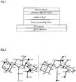
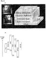
- FIG. 1 of the accompanying drawings An embodiment of an OLED is shown schematically in Figure 1 of the accompanying drawings, to illustrate a typical sequence of layers.
- a glass substrate is covered by a thin, optically transparent, layer of indium tin oxide (ITO), which acts as anode.
- ITO indium tin oxide
- a metal or metal alloy of low work function acts as cathode.
- the cathode and anode are separated by several layers of different organic molecules which are able to conduct charges, and provide the hole-transporting and emissive zones. Holes are injected into the organic layers from the anode, and electrons are injected from the cathode. The holes and the electrons migrate in opposite directions in the layers of the organic molecules and bind to form excitons.
- the anode injects into a hole-transporting layer (hole-transporting zone), which may, for example, comprise a hole-transporting material such as PEDOT:PSS [poly(3,4-ethylenedioxythiophene)/polystyrene sulfonate polymer mixture], while the cathode injects into an electron-injection layer, which may, for example, comprise an electron-transporting material such as a metal oxide, salt or organic electron-transporting compound. Both the hole-transporting layer and the electron-injection layer serve to block the escape of the opposite-sign charge carrier. Between these layers is the emissive layer, which is a layer of organic compounds in which excitons form in a mixture of spin-0 singlet and spin-1 triplet states.
- a hole-transporting layer such as PEDOT:PSS [poly(3,4-ethylenedioxythiophene)/polystyrene sulfonate polymer mixture]
- an electron-injection layer which may, for example,
- Layer devices such as that illustrated in Figure 1 are built up by successive deposition of the layers on the substrate.
- the deposition technique for each layer is selected from a range of available techniques.
- the cathode is typically generated by evaporating metal vapour on the top surface of the previously deposited layers.
- a common approach to forming the material of an emissive layer is to embed emitter molecules in a wider-bandgap organic matrix, usually at a level of 1 - 10 weight-percent.
- the role of the matrix is to allow excitons and charges to migrate to the emitter molecules.
- these emitter molecules are promoted to an excited state, which relaxes with the emission of light.
- This light can be of varying colour and can include white light.
- the emitter molecules can be of various types, such as, for example, organic compounds with no metal atoms, organometallic complexes of heavy transition metals, and metal coordination complexes.
- the key role of the heavy metals in the complexes is to enhance spin-orbit coupling and thus allow luminescence from the normally dark triplet exciton state, significantly increasing the achievable photon quantum yield.
- the device efficiency is improved when the emitters have excited states with short life times, reducing competition with non-radiative decay channels.
- WO2004/081017 A wide range of such metal complexes for applications as photo-emitters and based on polydentate ligand frameworks is described in WO2004/081017 .
- Particularly widely used as emitters are complexes of expensive noble metals, especially those of iridium, platinum and gold in high oxidation states, which are used in combination with polydentate chelating aromatic and heteroaromatic ligands.
- Emitter compounds based on these metals have been extensively patented and have for example been described in WO 2006/070896 , U.S. Pat. 2009/0278453 , WO2014/023377 , WO2013/097920 , WO2014/094960 , WO2014/094961 , WO2014/094962 and U.S. Pat. 2011/0012093 .
- WO2009/113646 describes certain substituted ethynyl gold-cyclic-(alkyl)(amino)carbene complexes and their use as organic electroluminescent elements.
- copper complexes are known to become luminescent when excited with UV light. These complexes contain copper in the coordination number three or, most commonly, coordination number four in a distorted tetrahedral geometry and are of the form Cu 2 X 2 L 4 , where L stands for a monodentate or part of a polydentate phosphine ligand. Copper and silver complexes of this type are for example described in WO 2014/102079 , and are based on binuclear halide-bridged structures and four-coordinate metal centres. Similar copper and silver complexes of bidentate phosphines coordinated to bidentate nitrogen donor ligands in place of halide ligands are described in WO 2014/108430 .
- the purpose of using heavy-metal emitters such as iridium is to enable fast inter-system crossing, so that the ligand-based excited triplet states can be harvested in the form of emitted light.
- excited triplet states in close proximity are known to suffer from triple-triplet annihilation, reducing electroluminescence yield.
- many existing organometallic emitter materials suffer from strong concentration quenching. Dilution within the host matrix is therefore necessary to achieve efficient luminescence, and gradual migration and aggregation of emitter molecules leads to device failure. There is therefore a need to develop emitters with high quantum efficiency in the solid state, reducing the impact of aggregation.
- Solution processing means in this context that the compound is capable of being dissolved, dispersed or suspended in a liquid medium.
- a solution, dispersion or suspension should be suitable for producing layer structures in OLED devices by coating or printing from a liquid phase, such as, for example, spin-coating, ink-jet printing or suitable alternative techniques.
- Electroluminescent devices Production costs of electroluminescent devices can be reduced using solution-based processing techniques, including a combination of solution processing and vacuum deposition techniques. With lowered production costs, the use of noble metal compounds as emitter materials can become economically attractive.
- Production of electroluminescent devices incorporating, as emitter materials, compounds of gold in the oxidation state +III and bonded to polydentate chelating aromatic ligands has been described, for example, in Chemistry A European Journal 2014, vol. 20, p. 15233-15241 , in Advanced Materials 2014, vol. 26, p. 2540-2546 , and in the Journal of the American Chemical Society 2014, vol. 136, p. 17861-17868 . However, the external quantum efficiencies of these devices were below 10-15%.
- the solid-state photoluminescence quantum yield of the copper compounds is: compound 1a 0.96 (96%); compound 1b 0.61 (61%); compound 1c 0.28 (28%).
- the solid-state photoluminescence quantum yield of the gold compounds is: compound 2a 0.09 (9%); compound 2b 0.13 (13%); compound 2c 0.18 (18%).
- the present invention provides complexes of the following Formula I: (L)M(X), (I) in which
- the complexes have a coordination number of 2. They are preferably electrically neutral, that is to say the metal M is present in the oxidation state (+1) and the monoanionic ligand X balances that charge.
- the carbene ligand L preferably has a neutral charge but may optionally carry an anionic (negatively charged) substituent.
- the carbene site of the ligand L provides a strong electron donating effect towards the metal atom M.
- the strong electron donation raises the energy of the d-orbitals on the metal atom M in the complex. Without wishing in any way to be bound by theory, it is hypothesized that this increase in the energy of the d-electrons of the metal facilitates the excitation process, for example facilitates metal-to-ligand charge transfer during the excitation process.
- the carbene C atom has an empty p-orbital which can act as electron acceptor. In copper complexes excited S 1 singlet and T' triplet states are close in energy, and there is the possibility that a thermal equilibrium between these two states is established.
- excited state lifetimes are very short, of the order of nanoseconds to low microseconds, so that emissive devices with high brightness can be constructed.
- Relaxation from triplet states is typified by phosphorescence, with excited state lifetimes of the order of ten to hundreds of microseconds, for example of the order of 100 microseconds, or more.
- the present invention provides a light-emitting device which is:
- a hole-transporting zone is present.
- a hole-transporting zone and an electron-transporting zone are present, the electron-transporting zone being disposed between the emissive zone and the cathode.
- the present invention provides a method of preparing complexes of Formula I according to the first aspect of the invention or complexes of Formula Ia for use in a light-emitting device according to the second aspect of the invention, the method comprising:
- M and X in the compound of Formula II each has the same exemplification and preferences as described below for the complex of Formula I or Ia.
- One preference for X in the compound of Formula II in which M is selected from copper, gold and silver is therefore halide.
- Suitable examples of such compounds of Formula II are copper (I) chloride, copper (I) bromide, copper (I) iodide, silver chloride, silver bromide and silver iodide.
- the inventors have investigated the photoemissive properties of complexes of Formula I according to the first aspect of the present invention and complexes of Formula Ia as defined in the second aspect of the present invention.
- the RASI pathway for photoemission is generally applicable to organometallic complexes which have the required combination of features discussed as 1 to 6 above, and constitutes the basis for further aspects of the present disclosure.
- the present disclosure provides a light-emitting device comprising an emissive zone capable of emitting light in response to introduced energy, wherein the emissive zone capable of emitting light comprises at least one organometallic complex which exhibits RASI photoemission.
- the light-emitting device may be an OLED.
- OLED employing RASI photoemission a ROLED or a molecular rotation-based OLED.
- the present disclosure provides a method of generating light comprising:
- the present disclosure provides the use of at least one organometallic complex which has been determined by specific investigation to exhibit RASI photoemission, in a light-emitting device for generating light.
- the organometallic complex(es) which exhibit(s) RASI photoemission may have at least the following combination of features:
- the energy gap E g between the HOMO and the LUMO of the carbene ligand L' is less than or equal to about 3.5 eV, for example less than or equal to about 3.0 eV.
- the organometallic complex used in the fourth, fifth and/or sixth aspects of the present disclosure can be or include any organometallic complex provided that it exhibits RASI photoemission.
- the carbene ligand L' may be any carbene ligand that provides the required RASI photoemission.
- the carbene ligand L' may be as defined for L in relation to the complexes of Formula I or Ia of the present invention.
- the metal atom M' may be any transition metal atom that provides the required RASI photoemission.
- the metal atom M' may be as defined for M in relation to the complexes of Formula I or Ia of the present invention.
- the monoanionic ligand X' may be any monoanionic ligand that provides the required RASI photoemission.
- the monoanionic ligand X' may be as defined for X in relation to the complexes of Formula I or Ia of the present invention.
- the at least one organometallic complex used in the fourth, fifth and/or sixth aspects of the present disclosure may be or comprise at least one complex according to Formula I or Ia as described herein.
- the organometallic complex which exhibits RASI photoemission has been determined by specific investigation to be an organometallic complex in which, when the molecule is energetically excited in the solid state, an electron will be promoted to a vibrationally excited S 1 * state which has a higher energy than T 1 and S 1 .
- the organometallic complex which exhibits RASI photoemission has been determined by specific investigation to be an organometallic complex in which the excited S 1 state of the complex is accessed from the vibrationally excited S 1 * state by geometrical relaxation of the molecule through rotation of the plane P2 to the third dihedral angle, whereby photoemission by fluorescence results from the subsequent relaxation from the S 1 state to the ground S 0 state.
- the organometallic complex which exhibits RASI photoemission has been determined by specific investigation to be an organometallic complex in which, as the dihedral angle changes by rotation of the plane P2 to the third dihedral angle, and the energy level of the molecule changes from S 1 * to S 1 , the first being higher than the triplet state T 1 and the second being lower than the triplet state T 1 , at an intermediate point in the process the energy levels of the excited singlet and excited triplet state of the molecule are equal.
- the at least one organometallic complex which exhibits RASI photoemission used in the light-emitting device according to the fourth aspect of the present disclosure, provided in the method according to the fifth aspect of the present disclosure, or used in the sixth aspect of the present disclosure, may suitably be at least one complex according to the first aspect of the present invention.
- the light-emitting device provided in the method according to the fifth aspect of the present disclosure, or used in the sixth aspect of the present disclosure, may be a photoluminescent device or an electroluminescent device, for example a ROLED.
- an electroluminescent device it may suitably comprise, in sequence, an anode, optionally a hole-transporting zone, the emissive zone as defined in the fourth aspect of the present invention, and a cathode.
- an electron-transporting zone is provided between the emissive zone and the cathode.
- the present invention provides a light-emitting device comprising an emissive zone capable of emitting light in response to introduced energy, wherein the emissive zone capable of emitting light comprises at least one organometallic complex of Formula I or Ia as defined in the first and second aspects of the present invention.
- the present invention provides the use of at least one organometallic complex of Formula I or Ia as defined in the first and second aspects of the present invention, in a light-emitting device for generating light.
- the light-emitting device according to the seventh aspect of the present invention or used in the eighth aspect of the present invention may be a photoluminescent device or an electroluminescent device, for example a ROLED.
- the light-emitting device according to the seventh aspect of the present invention or used in the eighth aspect of the present invention is an electroluminescent device, it may suitably comprise, in sequence, an anode, optionally a hole-transporting zone, the emissive zone as defined in the fourth aspect of the present invention, and a cathode.
- an electron-transporting zone is provided between the emissive zone and the cathode.
- the light-emitting device referred to in connection with the seventh and eighth aspects of the present invention may exclude photoluminescent and optionally other devices in which the sole photoemissive organometallic complex of Formula I or Ia present in the device is one or more complex selected from complexes having the formula Ad L-M-X and individually designated 1a, 1b, 1c, 2a, 2b and 2c according to the following scheme:
- the light-emitting device referred to in connection with the seventh and eighth aspects of the present invention may exclude photoluminescent and optionally other devices in which any photoemissive organometallic complex of Formula I or Ia present in the device is one or more complex selected from the said complexes having the formula Ad L-M-X and individually designated 1a, 1b, 1c, 2a, 2b and 2c.
- the metal atom M may be selected from copper, silver and gold.
- the oxidation state of M in the complexes may be (+I).
- the coordination number in the complexes is 2, that is, a linear configuration of metal and ligands.
- a cyclic alkyl amino carbene (CAAC) ligand having a saturated cyclic structure in which the atoms of the ring which includes the carbene site consist of carbon atoms and one nitrogen atom does not exclude the possibility that cyclic or non-cyclic structures which are not saturated may be linked to the ring which includes the carbene site.
- additional cyclic or non-cyclic structures may, for example, include aromatic rings.
- the expression "the atoms of the ring which includes the carbene site consist of carbon atoms and one nitrogen atom” refers to the atoms actually forming the ring which includes the carbene site, and does not exclude the possibility that atoms other than carbon and nitrogen may be linked to one or more of those ring-forming atoms, for example in substituent groups.
- the CAAC ligand L is preferably a compound of Formula III: in which
- R' and R" are linked to form an optionally substituted saturated cyclic hydrocarbyl group which may optionally contain one or more heteroatom
- the cyclic hydrocarbyl group may, for example, include one or more rings with 3 - 10 members, most preferably rings of six members, wherein the expression "members” refers to carbon atoms of the ring backbone and any heteroatoms present.
- the optionally substituted saturated cyclic hydrocarbyl group may, for example, be an optionally substituted C 3-8 cycloalkyl group; for example, >CR'R" may represent a cyclohexylidene moiety, otherwise known as a spirocyclohexane ring.
- >CR'R may be fused rings, which may if desired provide a cage structure; for example, >CR'R” may represent an adamantylidene moiety, otherwise known as a spiroadamantane ring system.
- D, E, G, d, e, g, and f are as defined above and F is >CR f R ff , in which R f and R ff , which may be the same or different, are selected from optionally substituted alkyl groups with 1 - 10 C atoms, or R f , R ff and the carbon atom C to which they are linked form an optionally substituted cyclic hydrocarbyl group optionally containing one or more heteroatom in the ring.
- the optionally substituted saturated cyclic hydrocarbyl group may, for example, be an optionally substituted C 3-8 cycloalkyl group (for example, >CR f R ff may represent a cyclohexylidene moiety or spirocyclohexane ring).
- D, E, G, d, e, g, and f are as defined above and F is >CMe 2 .
- D, E, G, d, e, g, and f are as defined above and F is >CR f R ff , in which R f and R ff and the carbon atom C to which they are linked form an optionally substituted fused bi-, trior poly-cyclic hydrocarbyl group optionally containing one or more heteroatom in at least one of the rings, for example a cage structure.
- F is an optionally substituted cycloalkylidene group (spirocycloalkane ring), preferably an unsubstituted adamantylidene group (spiroadamantane ring system).
- the CAAC ligand L may, for example, be a compound of Formula IIIa: wherein R a , R b , R c and R d are CH 3 groups, and Ar represents a substituted phenyl group, for example a substituted phenyl group in which the one or more substituents are independently selected from the options set out in the discussion of the term "optionally substituted” below (more preferably a 2,6-dialkyl substituted phenyl group, and most preferably a 2,6-diisopropylphenyl group).
- the CAAC ligand L may be a spiroadamantane compound of Formula IIIb: wherein R a and R b are CH 3 groups and Ar represents a substituted phenyl group, for example a substituted phenyl group in which the one or more substituents are independently selected from the options set out in the discussion of the term "optionally substituted” below (more preferably a 2,6-dialkyl substituted phenyl group, and most preferably a 2,6-diisopropylphenyl group).
- the CAAC ligand L may be selected from the following group of compounds: where R n represents a variable number n of 1 - 4 substituents, each of which is independently selected from the group comprising hydrogen, alkyl, alkenyl, alkynyl, alkoxy, amino, aryl and heteroaryl.
- R n 2 and the 2- and 6-positions in the N-bound aryl ring are occupied by substituents R, which substituents R are preferably the same. More preferably, the substituents in 2- and 6-positions are isopropyl groups.
- carbene ligand L includes one or more chiral carbon atom
- all individual stereoisomers and stereoisomeric mixtures, for example enantiomers and racemic mixtures, of the chiral forms are within the scope of the present invention.
- Tautomers of the ligand L are also encompassed within the scope of the definitions herein.
- X is a monoanionic ligand. Any inorganic or organic monoanion can be used, provided that the required 2-coordination complex of Formula I is obtained.
- the ligand X may, for example, be selected from a halide, pseudo-halide, optionally substituted alkoxide (for example unsubstituted alkoxide), optionally substituted aryloxide (for example unubstituted aryloxide), optionally substituted arylacetylide (for example, unsubstituted phenylacetylide), optionally substituted amide (for example, unsubstituted amide), optionally substituted carboxylate (for example, unsubstituted carboxylate), optionally substituted anilide (for example, unsubstituted anilide), optionally substituted carbazole, optionally substituted dihydroacridine, optionally substituted azepine, optionally substituted dibenzazepine, optionally substituted 10,11-dihydrodibenzazepine, optionally substituted phenazine, optionally substituted oxazine, optionally substituted acridone,
- Ligands X may be compounds of Formula IV [E-Ar] - (IV) wherein Ar is an optionally substituted aryl or optionally substituted heteroaryl group, and E- is selected from C(R 1 )(R 2 )-, O-, S-, Se-, Te-, N(R)-, P(R)-, As(R)- and Sb(R)-, in which R, R 1 and R 2 are independently chosen from hydrogen, optionally substituted alkyl, optionally substituted alkenyl, optionally substituted allyl, optionally substituted aryl and optionally substituted heteroaryl.
- R, R 1 and R 2 groups when present, may optionally be directly linked to the Ar moiety by one or more linker species as well as via the said C, N, P, As or Sb atom.
- Halides may suitably be selected from chlorides, bromides and iodides.
- pseudo-halides are cyanide, thiocyanate (SCN), cyanate (OCN), isocyanate (NCO) and isothiocyanate (NCS), isoselenocyanate (NCSe).
- Cz refers to carbazolate and DTBCz refers to 3,6-di- t butylcarbazolate.
- alkoxides for use as ligand X include, but are not limited to, linear or branched chain alkoxides having from 1 to 20 carbon atoms.
- aryl oxides for use as ligand X include, but are not limited to, phenolate, 2-methylphenolate, 2-tert.butyl-5-methylphenolate, 2,6-dimethylphenolate, 3,5-dimethylphenolate, 3.5-di- t -butylphenolate, 3,5-bis(trifluoromethyl)phenolate, 2-chlorophenolate, 2,6-dichlorophenolate, 2,6-difluorophenolate, 2,6-dibromophenolate, 2,6-diiodophenolate, 4-fluorophenolate, 4-trifluoromethylphenolate, 1-naphtholate, 2-naphtholate, and the like.
- the aryloxide ligand may be substituted by one or more of carbazolyl, (N-alkyl)carbazolyl or (N-aryl)carbazolyl substituents, where each carbazolyl moiety may carry one or more of prim.-, sec.- or tert .-alkyl substituents or any combination thereof.
- thiolates for use as ligand X include, but are not limited to, linear or branched chain thiolates having from 1 to 20 carbon atoms.
- thiophenolates for use as ligand X include, but are not limited to, thiophenolate, 2-methylthiophenolate, 2-tert.butyl-5-methylthiophenolate, 2,6-dimethylthiophenolate, 3,5-dimethylthiophenolate, 3.5-di- t -butylthiophenolate, 3,5-bis(trifluoromethyl) thiophenolate, 2-chlorothiophenolate, 2,6-dichlorothiophenolate, 2,6-difluorothiophenolate, 2,6-dibromothiophenolate, 2,6-diiodothiophenolate, 4-fluorothiophenolate, 4-trifluoromethylthiophenolate, 1-thionaphtholate, 2-thionaphtholate, and the like.
- the thiophenolate ligand may be substituted by one or more of carbazolyl, (N-alkyl)carbazolyl or (N-aryl)carbazolyl substituents, where each carbazolyl moiety may carry one or more prim.-, sec.- or tert .-alkyl substituents or any combination thereof.
- the group R in those representations may, for example, be chosen from alkyl, alkenyl, aryl and heteroaryl.
- X can be a ketiminate represented by R 1" R 2" CN - , in which R 1" and R 2" may independently be chosen from one or more alkyl, alkenyl, aryl and heteroaryl groups.
- X may be a guanidinate represented by [(R 1''' R 2''' N)C(NR 3''' )(NR 4''' )] - , in which R 1''' , R 2''' , R 3''' and R 4''' are independently chosen from one or more alkyl, alkenyl, aryl and heteroaryl groups.
- the ligand X is an optionally substituted amide group having the following general formula in which the nitrogen atom N is an amide anionic nitrogen: or or or or or or in which Rn, Rm and Rk represent optional substituents of the respective aromatic rings, in which n, m and k are numbers from 0 to the maximum available and in each case the presence, number, position and/or identity of the said substituents may be the same or different as between different aromatic ring moieties; and, where n, m or k is more than 1, the identity of each R group of the substituents of a particular aromatic ring moiety may be the same or different as between each other; and
- the ligand X may be a diarylamide or carbazolate anion.
- the aryl groups in the diarylamide anion or the aromatic rings in the carbazolate anion may each be optionally substituted.
- the diarylamide anion may, for example, be a diphenylamide anion (NPh 2 - ), in which the phenyl groups are each optionally substituted by one or more substituents, the presence, number, position and/or identity of which may be the same or different between the two phenyl groups.
- the substituent(s), when present, is/are suitably selected from the groups set out below in the discussion of the expression "Optionally substituted".
- An example of a preferred diarylamide ligand X is a diphenylamide anion.
- the carbazolate anion may, for example, be a carbazolate anion in which the aromatic rings are each optionally substituted by one or more substituents, the presence, number, position and/or identity of which may be the same or different between the two aromatic rings.
- the substituent(s), when present, is/are suitably selected from the groups set out below in the discussion of the expression "Optionally substituted”.
- Examples of preferred carbazolate ligands X are the carbazolate anion and the 3,6-di-t.butyl-carbazolate anion.
- Substituents within the definitions of Rn, Rm and Rk, and substituents of the diarylamide and carbazolate anions referred to above, may for example be selected from the group of alkyl, aryl, alkenyl, alkynyl, each of which may optionally be substituted (such substituted forms including, for example: haloalkyl (for example, fluoroalkyl containing one or more fluorine atoms, for example perfluoroalkyl), haloalkenyl (for example, fluoroalkenyl containing one or more fluorine atoms, for example perfluoroalkenyl), haloaryl (for example, fluoroaryl containing one or more fluorine atoms, for example perfluoroaryl)), NMe 2 , NO 2 , SO 3 H and COOH.
- haloalkyl for example, fluoroalkyl containing one or more fluorine atoms, for example perfluoro
- X is a monoanionic organic amide ligand having the formula R'-N-R" or N in which R' and R" are selected from hydrogen and organic groups, which when both organic groups may be the same or different; and represents a cyclic organic group which may contain one or more rings.
- Any monoanionic organic amide ligand X according to this definition may be present, such as those monoanionic organic amide ligands described above in relation to part A of the definition of Formula I of the present invention.
- Examples of complexes of Formula Ia used in the second aspect of the invention include those in which X is a monoanionic organic amide ligand having the formula R'-N-R" or N in which R' and R" are selected from hydrogen and organic groups, which when both organic groups may be the same or different; and represents a cyclic organic group which may contain one or more rings; and more preferably those in which M is copper or gold and X is a monoanionic organic amide ligand having the formula R'-N-R" or N in which R' and R" are selected from hydrogen and organic groups, which when both organic groups may be the same or different; and represents a cyclic organic group which may contain one or more rings.
- organic group refers to groups containing at least carbon covalently bonded to other atoms.
- X in a complexes of Formula I or Ia is a monoanionic organic amide ligand having the formula R'-N-R" or N in which R' and R" are selected from hydrogen and organic groups, which when both organic groups may be the same or different; and represents a cyclic organic group which may contain one or more rings; the organic group may preferably be an organic group containing at least carbon and hydrogen.
- Such an organic group may optionally contain one or more heteroatom, for example selected from B, N, O, P and S, and/or one or more halogen atom, for example selected from Cl, F and I.
- M is copper;
- L is a cyclic alkyl amino carbene (CAAC) ligand having a saturated cyclic structure in which the atoms of the ring which includes the carbene site consist of carbon atoms and one nitrogen atom;
- X is a monoanionic organic amide ligand having the formula R'-N-R" or N in which R' and R" are selected from hydrogen and organic groups, which when both organic groups may be the same or different; and represents a cyclic organic group which may contain one or more rings.
- CAAC cyclic alkyl amino carbene
- M is gold
- L is a cyclic alkyl amino carbene (CAAC) ligand having a saturated cyclic structure in which the atoms of the ring which includes the carbene site consist of carbon atoms and one nitrogen atom
- X is a monoanionic organic amide ligand having the formula R'-N-R" or N in which R' and R" are selected from hydrogen and organic groups, which when both organic groups may be the same or different; and represents a cyclic organic group which may contain one or more rings.
- Alkyl means an aliphatic hydrocarbon group.
- the alkyl group may be straight or branched.
- Branched means that at least one carbon branch point is present in the group.
- the alkyl group may suitably contain 1 - 20 carbon atoms, e.g. 2, 3, 4, 5, 6, 7, 8, 9, 10, 11, 12, 13, 14, 15, 16, 17, 18, 19 or 20 carbon atoms.
- Exemplary alkyl groups include methyl, ethyl, n -propyl, i -propyl, n -butyl, t -butyl, s -butyl, n -pentyl, 2-pentyl, 3-pentyl, n -hexyl, 2-hexyl, 3-hexyl, n -heptyl, 2-heptyl, 3-heptyl, 4-heptyl, 2-methyl-but-1-yl, 2-methyl-but-3-yl, 2-methyl-pent-1-yl, 2-methylpent-3-yl.
- the alkyl group may be optionally substituted, e.g. as exemplified below.
- Cycloalkyl means a cyclic non-aromatic hydrocarbon group.
- the cycloalkyl group may include non-aromatic unsaturation.
- Cycloalkyl groups may be mono- or polycyclic, and polycyclic cycloalkyl groups may be fused-ring, spiro, cage or combinations thereof.
- the cycloalkyl group preferably has 3 to 20 carbon atoms, e.g. 3, 4, 5, 6, 7, 8, 9, 10, 11, 12, 13, 14, 15, 16, 17, 18, 19 or 20 carbon atoms.
- Exemplary cycloalkyl groups include cyclopropyl, cyclobutyl, cyclopentyl, cyclohexyl, cyclopentenyl, cyclohexenyl norbornyl, adamantyl.
- the cycloalkyl group may be optionally substituted, as defined below, e.g. as exemplified below.
- Alkenyl means an unsaturated aliphatic hydrocarbon group which contains one or more double bond.
- the alkenyl group may be straight or branched. "Branched” means that at least one carbon branch point is present in the group.
- Any double bond may, independently of any other double bond in the group, be in either the (E) or the (Z) configuration.
- the alkenyl group is preferably an alkenyl group, straight or branched, having 2 to 20 carbon atoms, e.g. 2, 3, 4, 5, 6, 7, 8, 9, 10, 11, 12, 13, 14, 15, 16, 17, 18, 19 or 20 carbon atoms.
- alkenyl groups include ethenyl, n -propenyl, i -propenyl, but-1-en-1-yl, but-2-en-1-yl, but-3-en-1-yl, pent-1-en-1-yl, pent-2-en-1-yl, pent-3-en-1-yl, pent-4-en-1-yl, pent-1-en-2-yl, pent-2-en-2-yl, pent-3-en-2-yl, pent-4-en-2-yl, pent-1-en-3-yl, pent-2-en-3-yl, pentadien-1-yl, pentadien-2-yl, pentadien-3-yl.
- the alkenyl group may be optionally substituted, e.g. as exemplified below.
- Alkynyl means an unsaturated aliphatic hydrocarbon group which contains one or more triple bond.
- the alkynyl group may be straight or branched.
- Branched means that at least one carbon branch point is present in the group.
- the alkynyl group is preferably an alkynyl group, straight or branched, having 2 to 20 carbon atoms, e.g. 2, 3, 4, 5, 6, 7, 8, 9, 10, 11, 12, 13, 14, 15, 16, 17, 18, 19 or 20 carbon atoms.
- alkynyl groups include ethynyl, 1-propynyl, 1-butynyl, 2-butynyl.
- the alkynyl group may be optionally substituted, e.g. as exemplified below.
- Aryl means any aromatic group, preferably having up to about 20 carbon atoms, e.g. 6, 7, 8, 9, 10, 11, 12, 13, 14, 15, 16, 17, 18, 19 or 20 carbon atoms.
- the aryl group may comprise one, two or more rings. Where two or more rings are present they may if desired be fused.
- the aryl group preferably comprises one or more phenyl ring.
- Exemplary aryl groups include phenyl, naphthyl, biphenyl.
- the aryl group may be optionally substituted, e.g. as exemplified below.
- Heteroaryl means any aromatic monocyclic, bicyclic, or tricyclic ring which comprises carbon atoms and one or more ring heteroatoms, e.g., 1, 2, 3, 4, 5 or 6 heteroatoms, preferably independently selected from the group consisting of nitrogen, oxygen, phosphorus, silicon and sulfur. Heteroaryl groups preferably have a ring system containing from 5 to 20 ring atoms, e.g. 5, 6, 7, 8, 9, 10, 11, 12, 13, 14, 15, 16, 17, 18, 19 or 20 ring atoms. Where two or more rings are present they may if desired be fused.
- heteroaryl groups include pyridyl, pyrazinyl, pyrimidinyl, furayl, thiophenyl, pyrrolyl, oxazole, thiazole, pyrazole, imidazole, 1,2,3-triazole, 1,2,4-triazole, tetrazole, indole, purine, carbazole, benzindole, benzufuran, dibenzofuran, benzothiphene, azacarbazole, azabenzofuran, azadibenzothiophene.
- the heteroaryl group may be optionally substituted, e.g. as exemplified below.
- Hydrocarbyl group means any group consisting only of carbon and hydrogen atoms, provided that if so specified it may optionally contain one or more heteroatom and/or be optionally substituted, as discussed below. Hydrocarbyl groups may be cyclic, straight or branched, and may be saturated, unsaturated or aromatic. Cyclic hydrocarbyl groups may be mono- or polycyclic, and polycyclic hydrocarbyl groups may be fused-ring, spiro, cage or combinations thereof.
- the hydrocarbyl group may optionally contain one or more heteroatom, e.g., 1, 2, 3, 4, 5 or 6 heteroatoms, independently selected from the group consisting of nitrogen, oxygen, and sulfur.
- the hydrocarbyl group may be optionally substituted, e.g. as exemplified below.
- aryloxide means an O-linked aryl group or the anionic form of the corresponding aryl-OH compound.
- aryloxide compounds include, but are not limited to, phenolate, 2-methylphenolate, 2- t -butyl-5-methylphenolate, 2,6-dimethylphenolate, 3,5-dimethylphenolate, 3.5-di- t -butylphenolate, 3,5-bis(trifluoromethyl)phenolate, 2-chlorophenolate, 2,6-dichlorophenolate, 2,6-difluorophenolate, 2,6-dibromophenolate, 2,6-diiodophenolate, 4-fluorophenolate, 4-trifluoromethylphenolate, 1-naphtholate, 2-naphtholate.
- amide refers for example to the [NRR'] - anion, where R and R' independently can be a hydrogen, alkyl, alkenyl, alkynyl, aryl, heteroaryl, aralkyl, cycloalkyl, halogenated alkyl, or heterocycloalkyl group described above.
- R and R' may, for example, be connected to each other.
- An amide group may be optionally substituted, e.g. as exemplified below.
- amide includes, for example, an optionally substituted amide group having the following general formula in which the nitrogen atom N is an amide anionic nitrogen: or or or or or or in which Rn, Rm and Rk represent optional substituents of the respective aromatic rings, in which n, m and k are numbers from 0 to the maximum available and in each case the presence, number, position and/or identity of the said substituents may be the same or different as between different aromatic ring moieties; and, where n, m or k is more than 1, the identity of each R group of the substituents of a particular aromatic ring moiety may be the same or different as between each other; and
- the ligand X may be a diarylamide or carbazolate anion.
- the aryl groups in the diarylamide anion or the aromatic rings in the carbazolate anion may each be optionally substituted.
- the diarylamide anion may, for example, be a diphenylamide anion (NPh 2 - ), in which the phenyl groups are each optionally substituted by one or more substituents, the presence, number, position and/or identity of which may be the same or different between the two phenyl groups.
- the substituent(s), when present, is/are suitably selected from the groups set out below in the discussion of the expression "Optionally substituted".
- An example of a preferred diarylamide ligand X is a diphenylamide anion.
- the carbazolate anion may, for example, be a carbazolate anion in which the aromatic rings are each optionally substituted by one or more substituents, the presence, number, position and/or identity of which may be the same or different between the two aromatic rings.
- the substituent(s), when present, is/are suitably selected from the groups set out below in the discussion of the expression "Optionally substituted”.
- Examples of preferred carbazolate ligands X are the carbazolate anion and the 3,6-di-t.butyl-carbazolate anion.
- Substituents within the definitions of Rn, Rm and Rk, and substituents of the diarylamide and carbazolate anions referred to above, may for example be selected from the group of alkyl, aryl, alkenyl, alkynyl, each of which may optionally be substituted (such substituted forms including, for example: haloalkyl (for example, fluoroalkyl containing one or more fluorine atoms, for example perfluoroalkyl), haloalkenyl (for example, fluoroalkenyl containing one or more fluorine atoms, for example perfluoroalkenyl), haloaryl (for example, fluoroaryl containing one or more fluorine atoms, for example perfluoroaryl)), NMe 2 , NO 2 , SO 3 H and COOH.
- haloalkyl for example, fluoroalkyl containing one or more fluorine atoms, for example perfluoro
- Rn and Rm are the same as each other and are perfluoroalkyl.
- thiophenylate refers to aryl thiolates.
- the aryl portion of the thiophenylate group may be optionally substituted, e.g. as exemplified below.
- thiophenylate compounds include, but are not limited to, thiophenolate, 2-methylthiophenolate, 2- t -butyl-5-methylthiophenolate, 2,6-dimethylthiophenolate, 3,5-dimethylthiophenolate, 3.5-di- t -butylthiophenolate, 3,5-bis(trifluoromethyl)thiophenolate, 2-chlorothiophenolate, 2,6-dichlorothiophenolate, 2,6-difluorothiophenolate, 2,6-dibromothiophenolate, 2,6-diiodothiophenolate, 4-fluorothiophenolate, 4-trifluoromethylthiophenolate, 1-thionaphtholate, 2-thionaphtholate.
- phosphiniminate refers to the anionic form of compounds containing the [R 1 R 2 R 3 PN] - moiety, where R 1 , R 2 and R 3 are independently chosen from organic groups optionally containing heteroatoms, preferably selected from Si, P, O, S or N.
- the organic groups may suitably be selected from alkyl, alkenyl, aryl or heteroaryl groups.
- the phosphiniminate group may be optionally substituted, e.g. as exemplified below.
- the organic groups may suitably be selected from alkyl, alkenyl, aryl or heteroaryl groups.
- the ketiminate group may be optionally substituted, e.g. as exemplified below.
- guanidinate refers to the anionic form of compounds of the formula (R 1 R 2 N)C(NR 3 )(NR 4 ), namely [(R 1 R 2 N)C(NR 3 )(NR 4 )] - , where R 1 , R 2 , R 3 and R 4 are independently chosen from organic groups optionally containing heteroatoms, preferably selected from Si, P, O, S or N.
- the organic groups may suitably be selected from alkyl, alkenyl, aryl or heteroaryl groups.
- the guanidinate group may be optionally substituted, e.g. as exemplified below.
- Optionally substituted as applied to any group means that the said group may if desired be substituted with one or more substituents, which may be the same or different, preferably one or more substituents which individually have a size which is small in relation to the parent group being substituted (e.g. less than about 20% of the largest molecular dimension).
- a group cannot be a substituent of its own kind if it would thereby form a group of that kind which would then fall outside the definition of the compounds (e.g. an alkyl group cannot be a substituent of another alkyl group so that an alkyl group having too many carbon atoms would result).
- suitable substituents include halo (e.g.
- sulphoxide sulfone, sulphonyl, sulpho
- suitable substituents include halo (e.g.
- acyl means an H-CO- or C 1-20 alkyl-CO- group wherein the alkyl group is as defined below.
- Preferred acyls contain an alkyl.
- Exemplary acyl groups include formyl, acetyl, propanoyl, 2-methylpropanoyl and butanoyl.
- substituted alkyl groups include mono- or poly-aryl-substituted alkyl groups such as phenylmethyl, naphthylmethyl, diphenylmethyl, phenylethyl, naphthylethyl, diphenylethyl, phenylpropyl, naphthylpropyl, diphenylpropyl.
- Exemplary substituted cycloalkyl groups include mono- or poly-alkyl-substituted cycloalkyl groups such as 1-methylcyclopropyl, 1-methylcyclobutyl, 1-methylcyclopentyl, 1-methylcyclohexyl, 2-methylcyclopropyl, 2-methylcyclobutyl, 2-methylcyclopentyl, 2-methylcyclohexyl.
- Exemplary substituted aryl groups include, at any substitution position or combination of positions, C 1-20 alkoxyphenyl such as methoxyphenyl, hydroxyphenyl, (C 1-20 alkoxy)(hydroxy)phenyl such as methoxy-hydroxyphenyl, C 1-20 alkylphenyl such as methylphenyl, (C 1-20 alkyl)(hydroxy)phenyl such as methyl-hydroxyphenyl, monohalophenyl such as monofluorophenyl or monochlorophenyl, dihalophenyl such as dichlorophenyl or chlorofluorophenyl, carboxyphenyl, C 1-20 alkoxycarbonylphenyl such as methoxycarbonylphenyl.
- complexes of Formula Ia have the same examples, embodiments and preferences as the complexes of Formula I, with the exception that the compound Ad L-Au-NTf 2 in which Ad L is and Tf is CF 3 -SO 2 -; and the compounds wherein Dipp is 2,6-diisopropylphenyl; and the compounds wherein R is i Pr and Ar is 2,6- i Pr 2 C 6 H 3 ; and the compounds are excluded from complexes of Formula I.
- complexes 8A, 8B and 8C which may be mentioned include:
- the present invention provides a light-emitting device comprising, in sequence, an anode, optionally a hole-transporting zone, an emissive zone capable of emitting light when an electric current flows between the cathode and the anode, and a cathode.
- the emissive zone capable of emitting light comprises at least one complex of Formula I or Formula Ia.
- the light-emitting device is preferably constructed as a multilayer according to techniques known in the art.
- the basic layer arrangement stated above may be modified in a variety of ways known in the art, for example by incorporation of one or more additional layers or sub-layers, and by the provision of electrical conductors and means for housing and supporting the device in the desired position and orientation.
- the present invention also provides a light-emitting device comprising an emissive zone capable of emitting light in response to introduced energy, wherein the emissive zone capable of emitting light comprises at least one organometallic complex which exhibits RASI photoemission.
- the present invention provides a method of preparing a component for use in a light-emitting device according to the present invention, which comprises depositing on a substrate a layer of an organic emissive zone component from a solution thereof in a solvent, with the optional provision of one or more additional layers, components or combinations thereof on the substrate before, simultaneously with, and/or after the said deposition; and removing any solvent at any desired time to provide a component for use in a light emitting device.
- the component for use in the light-emitting device comprises at least the hole-transporting zone and emissive zone of the light-emitting device.
- the component for use in the light-emitting device can comprise layers or parts of the anode, the hole-transporting zone, the emissive zone and the cathode, optionally also an electron-injection layer.
- the depositions are simultaneous, sequential, or some of the layers are deposited simultaneously and some are deposited sequentially.
- the layers of the device according to the present invention may be deposited by any suitable method.
- preferred methods include thermal evaporation, ink-jet deposition (for example, as described in US Patents Nos. 6,013,982 and 6,087,196 ), organic vapour phase deposition (OVPD) (for example, as described in US Patent No. 6,337,102 ), or deposition by organic vapour jet printing (OVJP).
- Other suitable deposition methods include spin coating and other solution based processes. Solution based processes are preferably carried out in nitrogen or an inert gas atmosphere.
- preferred methods include thermal evaporation.
- Preferred patterning methods include deposition through a mask, cold welding such as described in US Patents Nos. 6,294,398 and 6,468,819 , and patterning associated with some of the deposition methods such as ink-jet and OVJD. Other methods may also be used.
- the materials to be deposited may be selected to make them compatible with a particular deposition method.
- substituents such as alkyl and aryl groups, branched or unbranched, and preferably containing at least 3 carbons, may be used in small molecules to enhance their ability to undergo solution processing. Substituents having 20 carbon atoms or more may be used, and 3-20 carbons is a preferred range. Materials with asymmetric structures may have better solution processibility than those having symmetric structures, because asymmetric materials may have a lower tendency to recrystallize. Dendrimer substituents may be used to enhance the ability of small molecules to undergo solution processing.
- solvents in which the complexes of the present invention may be dissolved or suspended for deposition in the manufacture of light-emitting devices include without limitation halogenated alkanes (for example, chloroform, dichloromethane, 1,2-dichloroethane or trichloroethane); aromatic solvents (for example, benzene, toluene, chlorobenzene, fluorobenzene, difluorobenzene or dichlorobenzene); ethers (for example, diethyl ether, tetrahydrofuran or methylated tetrahydrofuran); ketones (for example, acetone or methyl ethyl ketone); alcohols (for example, methanol or higher alcohols); acetonitrile; nitromethane; nitrobenzene; esters (for example, ethyl acetate); or any combination of one or more thereof.
- halogenated alkanes for example, chloroform, dichlorome
- Examples of light-emitting devices according to the present invention include organic light-emitting diodes (OLEDs), organic phototransistors, organic photovoltaic cells and organic photodetectors.
- OLEDs for example, are of interest for flat panel displays, illumination and backlighting. Examples of configurations and constructions of OLEDs are given in US Patent Nos. 5,844,363 , 6,303,238 and 5,707,745 .
- Light-emitting devices in accordance with the present invention may be incorporated into a wide variety of consumer products, including without limitation flat panel displays, computer monitors, televisions, billboards, lights for interior or exterior illumination and/or signaling, heads up displays, fully transparent displays, flexible displays, laser printers, telephones, cell phones, personal digital assistants (PDAs), laptop computers, digital cameras, camcorders, viewfinders, micro-displays, vehicles, a large area wall, theatre or stadium screen, or a sign.
- Pixel control systems and technologies may be used in known manner with the devices of the present invention, to control the images presented to the viewer. Such pixel control systems include without limitation passive matrix and active matrix technologies.
- the complexes of the present invention may, for example, be made by solution processing.
- the present invention provides a method of preparing the complexes, the method comprising contacting a compound of Formula II: M-X (II) with the CAAC compound L in a solvent, and recovering the complex of Formula I or Ia.
- M and X in the compound of Formula II each has the same exemplification and preferences as described herein for the complex of Formula I or Ia.
- One preference for X in the compound of Formula II is therefore halide.
- Suitable examples of compounds of Formula II are copper (I) chloride, copper (I) bromide, copper (I) iodide, silver chloride, silver bromide and silver iodide.
- the contacting of the reagents suitably takes place in water-free conditions, and preferably under an inert atmosphere (for example, nitrogen or argon).
- the complexing solvent may suitably be selected from halogenated alkanes (for example, chloroform, dichloromethane, 1,2-dichloroethane or trichloroethane); aromatic solvents (for example, benzene, toluene, chlorobenzene, fluorobenzene, difluorobenzene or dichlorobenzene); ethers (for example, diethyl ether, tetrahydrofuran or methylated tetrahydrofuran); ketones (for example, acetone or methyl ethyl ketone); alcohols (for example, methanol or higher alcohols); acetonitrile; nitromethane; nitrobenzene; esters (for example, ethyl acetate); and any combination of one or more thereof.
- Recovery of the complex from the solvent may suitably be achieved by evaporation of the solvent or by the use of an appropriate countersolvent, for example an alkane (for example, hexane or light petroleum ether).
- the recovered complex may be dried, suitably under vacuum, to recover the dry material.
- CAACs Cyclic (Alkyl)(Amino)Carbenes
- the compound of Formula I or Ia may be prepared by a method comprising contacting a CAAC compound of Formula Ib: L-Cu-X' (Ib) in which L is as defined for Formula I and X' is Cl, OH or O'Bu with a compound of formula V X-H (V) in which X is optionally substituted arylacetylide, optionally substituted aryloxide, or optionally substituted aryl amide, in a solvent, and recovering the complex of Formula I or Ia.
- a CAAC compound of Formula Ib: L-Cu-X' (Ib) in which L is as defined for Formula I and X' is Cl, OH or O'Bu with a compound of formula V X-H (V) in which X is optionally substituted arylacetylide, optionally substituted aryloxide, or optionally substituted aryl amide, in a solvent, and recovering the complex of Formula I or Ia.
- the present invention provides a further method of preparing the complexes, the method comprising contacting a CAAC compound of Formula Ic: L-Au-X' (Ic) in which L is as defined for Formula I or Ia and X' is Cl or OH or O'Bu with a compound of formula Va X-H (Va) in which X is optionally substituted aryl amide having the formula R'-N-R" or N in which R' and R" are selected from hydrogen and organic groups, which when both organic groups may be the same or different; provided that at least one of R and R" is aryl; and represents a cyclic organic group which may contain one or more rings; provided that the cyclic organic group is such that the compound of formula Va is an optionally substituted aryl amide; in a solvent, and recovering the complex of Formula I or Ia.
- the method of contacting the compound of Formula Ib or Ic with the compound of Formula V or Va may, for example, be carried out in dry tetahydrofuran, optionally containingor sodium tert-butoxide, under an inert atmosphere, for example under an argon atmosphere.
- the mixture may, for example, be centrifuged and the solution containing the product separated.
- formula VI shows the most common type of prior art N-heterocyclic carbene (NHC) compound, based on the imidazole or imidazolidine ring, which contains two nitrogen atoms in an unsaturated ring system: wherein R w , R x , R y and R z are the variable groups known from the prior art in these molecules.
- NHCs such as those of Formula VI mentioned above
- different types of carbene ligands differ significantly in their electronic properties.
- the structures, electronic and steric properties of carbenes and their coordination to metal centres have been summarised in several literature reviews, see for example: F. E. Hahn, M. C. Jahnke: “Heterocyclic Carbenes - Synthesis and Coordination Chemistry", Angewandte Chemie International Edition 2008, 47, 3122-3172 ; M. N. Hopkinson, C. Richter, M. Schedler, F.
- dicationic binuclear copper complexes where each metal centre is coordinated to two connected imidazole-type NHC ligands which hold the metal centres in close proximity, have been reported to show photoluminescent behaviour, with moderate quantum yield [ K. Matsumoto et al., Dalton Transactions 2009, 6795-6801 ].
- charged complexes are undesirable, and linked bis(carbene) ligands involve an undesirable level of synthetic complexity.
- Three-coordinate copper complexes involving one NHC ligand per metal centre are also known to be photoemissive and have been described in detail for example in U.S. Pat. 2014/125221 .
- the complexes in the present invention differ from these prior known NHC-copper complexes in that they have a coordination number of 2, the carbene species contains only one ring nitrogen atom, and only one carbene species is present.
- the complexes of the present invention have the potential to emit light via RASI photoemission, offering the possibility of light-emitting devices with high quantum efficiency.
- Bertrand "Cyclic (Alkyl)(Amino)Carbenes (CAACs): Stable Carbenes on the Rise", Accounts of Chemical Research 2015, 48, 256-266 , and O. Back, M. Henry-Ellinger, C. D. Martin, D. Martin, and G. Bertrand: "31P NMR Chemical Shifts of Carbene-Phosphinidene Adducts as an Indicator of the ⁇ -Accepting Properties of Carbenes", Angew. Chem. Int. Ed. 2013, 52, 2939 -2943 ]. The same applies to carbenes of formula III with larger rings.
- the substituents on the CAAC ring carbon atom that is adjacent to the carbene centre provide steric hindrance.
- the steric hindrance is further increased by using a bulky N-substituent R 1 .
- further substituents may, if desired be introduced to make the steric effects even more pronounced.
- the strong electron donation raises the energy of the d-orbitals on the metal atom M, for example copper. Without wishing in any way to be bound by theory, it is hypothesized that this increase in the energy of the d-electrons of the metal facilitates metal-to-ligand charge transfer during the excitation process.
- the carbene C atom has an empty p-orbital which can act as electron acceptor.
- excited S 1 singlet and T 1 triplet states are close in energy, and there is the possibility that a thermal equilibrium between these two states is established.
- the emission pathways from S 1 or T 1 states may, for example, include the RASI photoemission pathway described herein.
- the complexes of the present invention offer good solubility in organic solvents.
- Organic solvents are used during the construction of printed OLED devices, for example, and adequate solubility of the emissive complexes is important for their incorporation.
- the complexes of the present invention enable materials which potentially have very high internal quantum efficiency, for example equal to or greater than about 75%, e.g. equal to or greater than about 80%, equal to or greater than about 85%, equal to or greater than about 90%, equal to or greater than about 95%, equal to or greater than about 96%, equal to or greater than about 97% or equal to or greater than about 98%.
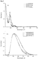
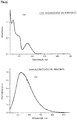
- FIGs 4 and 5 show the emission spectra of ( Ad CAAC)CuCl in different solvents (tetrahydrofuran (THF), acetonitrile, 1,4-dioxane, ethanol, pyridine and acetone).
- solvents tetrahydrofuran (THF), acetonitrile, 1,4-dioxane, ethanol, pyridine and acetone.
- the complex was prepared as described for Example 1 from Ad CAAC: (0.32 g, 0.86 mmol) and CuCN (77 mg, 0.86 mmol) as a white powder. Yield: 0.34 g (0.73 mmol, 86 %).
- the complex was prepared as described for Example 1 from Ad CAAC: (0.30 g, 0.80 mmol) and CuSCN (96 mg, 0.80 mmol) as a white powder. Yield 0.34 g (0.68 mmol, 86 %).
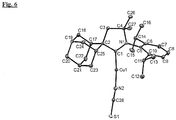
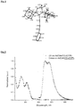
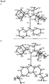
- the crystal structure is shown in Figure 6 .
- Figure 8 shows the crystal structure of the complex.
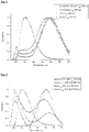
- Figure 9 shows the UV/vis and emission spectra of ( Ad CAAC)Cu(CCPh).
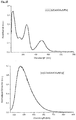
- Figure 10 shows the UV/vis and emission spectra of ( Ad CAAC)CuOPh.
- Figure 11 shows the UV/vis and emission spectra of this complex.
- Figure 12 shows the X-ray structure of this complex (data given in the summary of Figure 12 above).
- the complexes according to the present invention offer several advantages for use in OLED devices, such as short excitation lifetimes in the range of nanoseconds to tens of microseconds.
- the photophysical properties of representative examples were determined and are shown in Table 1 below. It should be noted that some of the quantum yields were measured in air, which explains surprisingly low yields in some cases.
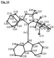
- Figure 14 shows the X-ray structure of this complex (data given in the summary of Figure 14 above).
- Figure 25b shows the X-ray structure of this complex (data given in the summary of Figure 25b above).
- Figure 15 shows the UV/vis and emission spectra of this complex and Figure 25a shows the X-ray structure of this complex (data given in the summary of Figure 25a above).
- Example 14 Following the procedure described in Example 14, the compound was made from Ad CAACAuCl (0.182 g, 0.30 mmol), NaO t Bu (31 mg, 0.32 mmol) and 2,6-dimethylphenol (37 mg, 0.3 mmol) as a white powder. Yield: 0.195 g (0.28 mmol, 93 %).
- the performance of the OLED devices based on CMA1-4 is shown in Figures 18 , 23 and 24 .
- a multi-layer device structure of Glass/ITO/PEDOT:PSS/TFB/PVK:CMA/BPhen/LiF/Al is used.
- the functions of the layers can be described in reference to the OLED structure shown in Figure 1 .
- the PVK and CMA blend forms the emissive zone.
- PEDOT:PSS and TFB layers form the hole transporting layer.
- the electron injection layer is comprised of BPhen and LiF.
- Al is the cathode material.
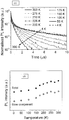
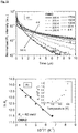
- FIG 16 shows photoluminescence (PL) decay data of ( Ad CAAC)Au(carbazolate) (CMA1) measured by time-correlated single photon counting (TCSPC).
- PL photoluminescence
- CMA1 time-correlated single photon counting
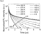
- FIG 17 shows temperature-dependent photoluminescence decay data of ( Ad CAAC)Au(carbazolate) (CMA1) measured by an electrically-gated intensified charge coupled device (CCD).
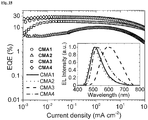
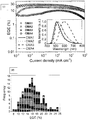
- Figure 18a shows the external quantum efficiency in OLEDs incorporating ( Ad CAAC) metal carbazolate CMA complexes, as a function of current density.
- CAAC 2-coordinate cyclic (alkyl)(amino)-carbene
- Cyclic voltammograms of CMA1 and CMA2 are shown in Figure 26 .
- the complexes CMA1 to CMA4 are soluble in a range of organic solvents, do not undergo ligand rearrangement reactions in solution, and are thermally stable to > 270 °C, as shown in Table 2:
- Table 2 Decomposition temperatures for CMA1-4 by thermal gravimetric analysis (TGA).
- TGA thermal gravimetric analysis
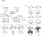
- the excited state energies of CMA1-4 were computed using density functional theory (DFT) and time-dependent density functional theory (TD-DFT) with optimisation of the molecular geometry.
- DFT density functional theory
- TD-DFT time-dependent density functional theory
- the ground state So and the relaxed triplet state T 1 correspond to a geometry with the carbene and carbazole ligands being co-planar
- the relaxed singlet state S 1 corresponds to a geometry with the carbazole ligand being rotated by 90°.
- Calculated oscillator strength for the S 0 ⁇ S 1 * transition in CMA1 is three orders of magnitude higher than that of the S 0 ⁇ S 1 transition in the fully relaxed geometry.
- the lowest strong optical absorption is therefore primarily from S 0 to S 1 *, while emission can occur from both S 1 * and S 1 .
- Solid films of CMA1-4 are photoluminescent, as has been observed in carbene metal halide compounds 14 .
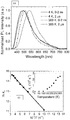
- Absorption spectra for a spin-coated film of CMA1 has an onset at approximately 450 nm ( Figure 21a ), in good agreement with the DFT calculations.
- Time-resolved PL spectra of CMA1 on ns- ⁇ s timescales at 300K, Figure 21b show a red shift of the PL peak position from approximately 500 nm at early times (0-2 ns), to approximately 540 nm at 2 ⁇ s.
- the emissive species at early times is therefore spectrally distinct from the emissive species at late times, in contrast to the behaviour of thermally activated delayed fluorescence (TADF) compounds 5 .
- TADF thermally activated delayed fluorescence
- the lifetime of the red-shifted slow component decreases from approximately 5 ⁇ s at 4K to approximately 350 ns at 300K ( Figure 21c ), while its intensity increases, leading to an increase in the total PL intensity with temperature ( Figure 21d ).
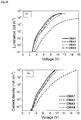
- FIG. 23a The performance of molecular rotation-based OLED (ROLEDs) is shown in Figure 23a .
- the energy levels of the materials used are shown in Figure 23b .
- HOMO/LUMO energies of CMA1-4 are shown in Table 4: Table 4: Formal electrode potentials for the compounds. Formal electrode potentials ( E 1/2 for irreversible and E' for reversible processes (*) vs . FeCp 2 ), onset potentials (E vs .
- E HOMO -( E onset ox Fc / Fc + + 5.39) e V, based on first oxidation potential
- E LUMO -( E onset red Fc / Fc + + 5.39) e V, based on first reduction potential.
- TFB 17 was deposited on PEDOT:PSS to form the hole-transporting layer, while CMA1-4 dispersed in a wide-bandgap polymer host PVK 4,18 were used as the emissive layer, followed by BPhen/LiF electron-injection layer.
- the electroluminescence (EL) spectra and the external quantum efficiency (EQE) of the best ROLEDs are shown in Figures 18 , 23c , 24a and 24b and in Table 5: Table 5: Summary of ROLED performances (best devices). Efficiency values at different brightness (100 cd m -2 and 1000 cd m -2 ) are shown. Emitter Turn-on Voltage (V) EQE (%) Current Efficiency (cd A -1 ) Power Efficiency (lm W -1 ) Max.
- Angular emission profiles for the devices showed Lambertian emission ( Figure 24c ), as is typical for OLEDs without microcavity outcoupling 19 , and allowed accurate estimation of EQE from on-axis irradiance. Consistent with this, the Commission Internationale de l'Éclairage (CIE) colour coordinates of the devices showed no observable variation with EQE ( Figures 24d and 24e ).
- Figure 23d shows the maximum EQE histogram of 135 ROLEDs using CMA4, which produced the most efficient devices. Performance metrics are summarised in Table 2 above.
- the EQEs of the best devices at practical brightness (100 & 1000 cd m -2 ), higher than 25%, are higher than the best solution-processed LEDs 7, 20 without enhanced optical outcoupling, while the peak EQE of our best device reached 27.5%.
- TCSPC Time-correlated single photon counting
- the solid-state samples for TCSPC studies were spin-coated from anhydrous tetrahydrofuran solutions (10 mg/mL) onto pre-cleaned quartz substrates. The samples were placed under high vacuum for 15 min to remove the solvent. The samples were photoexcited using a 407 nm pulsed laser with pulse width ⁇ 200 ps, at a repetition rate of 2.5 MHz. The photoluminescence was detected by a Si-based single-photon avalanche photodiode. The instrument response function has a lifetime of about 200 ps. A 420 nm long-pass filter was used to screen out any scattered laser signal in the optical path.
- Time-resolved PL spectra were recorded using an electrically-gated intensified CCD (ICCD) camera (Andor iStar DH740 CCI-010) connected to a calibrated grating spectrometer (Andor SR303i).
- SHG second harmonic generation
- Ti:Sapphire laser system Spectra Physics Solstice
- a 420 nm long-pass filter was used to prevent scattered laser signal from entering the camera.
- Temporal evolution of the PL emission was obtained by stepping the ICCD gate delay with respect to the excitation pulse.
- the minimum gate width of the ICCD was approximately approximately 2.5 ns.
- the cooling of the samples was provided by liquid helium, and the temperature of the samples was regulated using a temperature-controlled cryostat.
- PL slow PL slow 0 e ⁇ k 0 + k T t
- ln k T ⁇ E A k B 1 T + C where C is a constant.
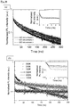
- the EL spectra of the devices were recorded using the calibrated ICCD-spectrometer set-up used in the PL measurements. The accuracy of the spectral data was cross-checked against a Labsphere CDS-610 spectrometer, as well as a Minolta CS-1000 luminance meter. Current density-voltage-luminance (J-V-L) characteristics were measured using a Minolta CS-200 luminance meter and a Keithley 2400 source-meter. The EQE of the devices were calculated based on the Lambertian emission profile measured.
- the accuracy of the EQE measurements for a subset of devices was checked using a calibrated silicon photodiode with known spectral response function, a Minolta CS-1000 luminance meter, as well as an integrating sphere.
- the devices were electrically excited by a function generator using 1 kHz square voltage (current) pulses with a pulse width of 0.5 ms for the on-cycles (forward bias).
- the off-cycles of the device operation were provided by a reverse bias of -4 V to eliminate charge accumulation effects.
- the instrument response time of the function generator was approximately 10 ns.
- the transient-EL of the samples was recorded by the same ICCD spectrometer used in the PL measurements.
- Cyclic voltammetry was performed using a three-electrode configuration consisting of either a glassy carbon macrodisk working electrode (GCE) (diameter of 3 mm; BASi, Indiana, USA) combined with a Pt wire counter electrode (99.99%; GoodFellow, Cambridge, UK) and an Ag wire pseudoreference electrode (99.99%; GoodFellow, Cambridge, UK).
- GCE glassy carbon macrodisk working electrode
- Pt wire counter electrode 99.99%; GoodFellow, Cambridge, UK
- Ag wire pseudoreference electrode 99.99%; GoodFellow, Cambridge, UK
- the Ag wire pseudoreference electrodes were calibrated to the ferrocene/ferrocenium couple in MeCN at the end of each run to allow for any drift in potential, following IUPAC recommendations S2 . All electrochemical measurements were performed at ambient temperatures under an inert Ar atmosphere in MeCN containing complex under study (0.14 mM) and supporting electrolyte [n-Bu 4 N][PF 6 ] (0.13 mM). Data were recorded with Autolab NOVA software (v. 1.11). Elemental analyses were performed by the London Metropolitan University.
- the crystals suitable for X-ray study for CMA2 and CMA4 were obtained by layering CH 2 Cl 2 solution with hexanes at -20 °C.
- Alert B is originated from the restriction of the resolution range of the data which was imposed by SHEL statement on the final refinement step.
- One of the t Bu-groups was disordered into two positions with equal occupancies for CMA4.
- DFIX statement was used to adopt a tetrahedral geometry for the disordered groups of atoms.
- the structures were solved by direct methods and refined by the full-matrix least-squares against F 2 in an anisotropic (for non-hydrogen atoms) approximation.
- the ground states were fully optimised by the hybrid density functional PBE0 method S5,S6 in combination with def2-TZVP basis set of Ahlrichs and coworkers S7,S8 .
- Relativistic effective core potential of 60 electrons was used to describe the core electrons of Au S9,S10 .
- the excited states were calculated for both relaxed and ground state geometries using TD-DFT S11 .
- the methods and basis sets have been previously employed with success in studies of luminescent Cu- and Au-complexes S12,S13 . All calculations were carried out by Gaussian 09 S14 .
- the singlet decay processes are characterised by k r S (radiative decay of singlets) and k nr S (non-radiative decay of singlets).
- k r S radiative decay of singlets
- k nr S non-radiative decay of singlets
- k r T radiatative decay of triplets
- k nr T non-radiative decay of triplets
- both k ISC and k RISC may be thermally activated, e.g. through the promotion of molecular rotation.
- k ISC and k RISC may be thermally activated, e.g. through the promotion of molecular rotation.
- PL slow PL slow 0 e ⁇ k 0 + k T t
Landscapes
- Chemical & Material Sciences (AREA)
- Organic Chemistry (AREA)
- Engineering & Computer Science (AREA)
- Materials Engineering (AREA)
- Inorganic Chemistry (AREA)
- Physics & Mathematics (AREA)
- Optics & Photonics (AREA)
- Electroluminescent Light Sources (AREA)
Applications Claiming Priority (3)
| Application Number | Priority Date | Filing Date | Title |
|---|---|---|---|
| GBGB1516230.8A GB201516230D0 (en) | 2015-09-14 | 2015-09-14 | Complexes of copper and silver |
| GBGB1609707.3A GB201609707D0 (en) | 2016-06-03 | 2016-06-03 | Metal complexes |
| PCT/GB2016/052797 WO2017046572A1 (en) | 2015-09-14 | 2016-09-09 | Metal complexes |
Publications (2)
| Publication Number | Publication Date |
|---|---|
| EP3350189A1 EP3350189A1 (en) | 2018-07-25 |
| EP3350189B1 true EP3350189B1 (en) | 2021-03-10 |
Family
ID=56926229
Family Applications (1)
| Application Number | Title | Priority Date | Filing Date |
|---|---|---|---|
| EP16766064.6A Active EP3350189B1 (en) | 2015-09-14 | 2016-09-09 | Metal complexes |
Country Status (7)
| Country | Link |
|---|---|
| US (1) | US10700295B2 (cg-RX-API-DMAC7.html) |
| EP (1) | EP3350189B1 (cg-RX-API-DMAC7.html) |
| JP (2) | JP6960633B2 (cg-RX-API-DMAC7.html) |
| KR (1) | KR20180055853A (cg-RX-API-DMAC7.html) |
| CN (1) | CN108699086B (cg-RX-API-DMAC7.html) |
| AU (1) | AU2016322694B2 (cg-RX-API-DMAC7.html) |
| WO (1) | WO2017046572A1 (cg-RX-API-DMAC7.html) |
Families Citing this family (6)
| Publication number | Priority date | Publication date | Assignee | Title |
|---|---|---|---|---|
| US11038115B2 (en) | 2017-05-18 | 2021-06-15 | Universal Display Corporation | Organic electroluminescent materials and device |
| US12180230B2 (en) | 2017-11-28 | 2024-12-31 | University Of Southern California | Carbene compounds and organic electroluminescent devices |
| US11306681B2 (en) * | 2019-01-15 | 2022-04-19 | The Boeing Company | Sheared exhaust nozzle |
| KR102867203B1 (ko) | 2020-07-13 | 2025-10-16 | 삼성디스플레이 주식회사 | 발광 소자, 이를 포함한 전자 장치 및 유기금속 화합물 |
| US20230165135A1 (en) * | 2021-11-23 | 2023-05-25 | Versitech Limited | d10 METAL CARBENE COMPLEXES FOR OLED APPLICATIONS |
| CN117024450A (zh) * | 2023-07-18 | 2023-11-10 | 武汉大学 | 一种卡宾货币金属配合物及其制备与应用 |
Citations (3)
| Publication number | Priority date | Publication date | Assignee | Title |
|---|---|---|---|---|
| US20130190510A1 (en) * | 2011-07-22 | 2013-07-25 | The Regents Of The University Of California | Neutral Tricoordinate Organoboron Derivatives Isoelectronic with Amines and Phosphines |
| US8580990B2 (en) * | 2008-05-09 | 2013-11-12 | The Regents Of The University Of California | Gold catalyzed hydroamination of alkynes and allenes |
| US20150108451A1 (en) * | 2013-10-23 | 2015-04-23 | University Of Southern California | Organic electroluminescent materials and devices |
Family Cites Families (3)
| Publication number | Priority date | Publication date | Assignee | Title |
|---|---|---|---|---|
| TW200946537A (en) * | 2008-03-13 | 2009-11-16 | Ube Industries | Substituted ethynyl golden-cyclic alkylaminocarbene complex and organic electroluminescent element |
| US8580394B2 (en) * | 2009-11-19 | 2013-11-12 | Universal Display Corporation | 3-coordinate copper(I)-carbene complexes |
| JP6284336B2 (ja) | 2013-10-17 | 2018-02-28 | ルネサスエレクトロニクス株式会社 | 半導体装置 |
-
2016
- 2016-09-09 AU AU2016322694A patent/AU2016322694B2/en active Active
- 2016-09-09 CN CN201680053084.2A patent/CN108699086B/zh active Active
- 2016-09-09 US US15/760,037 patent/US10700295B2/en active Active
- 2016-09-09 JP JP2018532833A patent/JP6960633B2/ja active Active
- 2016-09-09 KR KR1020187010540A patent/KR20180055853A/ko not_active Ceased
- 2016-09-09 WO PCT/GB2016/052797 patent/WO2017046572A1/en not_active Ceased
- 2016-09-09 EP EP16766064.6A patent/EP3350189B1/en active Active
-
2021
- 2021-07-02 JP JP2021110974A patent/JP7306615B2/ja active Active
Patent Citations (3)
| Publication number | Priority date | Publication date | Assignee | Title |
|---|---|---|---|---|
| US8580990B2 (en) * | 2008-05-09 | 2013-11-12 | The Regents Of The University Of California | Gold catalyzed hydroamination of alkynes and allenes |
| US20130190510A1 (en) * | 2011-07-22 | 2013-07-25 | The Regents Of The University Of California | Neutral Tricoordinate Organoboron Derivatives Isoelectronic with Amines and Phosphines |
| US20150108451A1 (en) * | 2013-10-23 | 2015-04-23 | University Of Southern California | Organic electroluminescent materials and devices |
Non-Patent Citations (2)
| Title |
|---|
| HOLGER BRAUNSCHWEIG ET AL: "Organometallic Probe for the Electronics of Base-Stabilized Group 11 Metal Cations", CHEMISTRY - A EUROPEAN JOURNAL, vol. 21, no. 35, 14 July 2015 (2015-07-14), DE, pages 12347 - 12356, XP055315595, ISSN: 0947-6539, DOI: 10.1002/chem.201500788 * |
| HOLGER BRAUNSCHWEIG ET AL: "Supporting Information Organometallic Probe for the Electronics of Base-Stabilized Group 11 Metal Cations", 14 July 2015 (2015-07-14), pages 1 - 23, XP055685057, Retrieved from the Internet <URL:https://chemistry-europe.onlinelibrary.wiley.com/action/downloadSupplement?doi=10.1002/chem.201500788&file=chem_201500788_sm_miscellaneous_information.pdf> [retrieved on 20200414] * |
Also Published As
| Publication number | Publication date |
|---|---|
| KR20180055853A (ko) | 2018-05-25 |
| WO2017046572A1 (en) | 2017-03-23 |
| JP2021169469A (ja) | 2021-10-28 |
| JP6960633B2 (ja) | 2021-11-05 |
| EP3350189A1 (en) | 2018-07-25 |
| CN108699086A (zh) | 2018-10-23 |
| AU2016322694A1 (en) | 2018-04-26 |
| AU2016322694B2 (en) | 2021-06-24 |
| JP7306615B2 (ja) | 2023-07-11 |
| JP2018528271A (ja) | 2018-09-27 |
| US10700295B2 (en) | 2020-06-30 |
| CN108699086B (zh) | 2021-08-20 |
| US20190131549A1 (en) | 2019-05-02 |
Similar Documents
| Publication | Publication Date | Title |
|---|---|---|
| JP7306615B2 (ja) | 金属錯体 | |
| Lee et al. | Deep-blue phosphorescence from perfluoro carbonyl-substituted iridium complexes | |
| Costa et al. | Efficient and Long‐Living Light‐Emitting Electrochemical Cells | |
| Mauro et al. | Highly emitting neutral dinuclear rhenium complexes as phosphorescent dopants for electroluminescent devices | |
| Chen et al. | Highly efficient cuprous complexes with thermally activated delayed fluorescence and simplified solution process OLEDs using the ligand as host | |
| Lin et al. | Photo-and electro-luminescence of three TADF binuclear Cu (I) complexes with functional tetraimine ligands | |
| Xu et al. | Efficient OLEDs with low efficiency roll-off using iridium complexes possessing good electron mobility | |
| Lin et al. | Unprecedented Homoleptic Bis‐Tridentate Iridium (III) Phosphors: Facile, Scaled‐Up Production, and Superior Chemical Stability | |
| CN102227439B (zh) | 络盐 | |
| Fernández-Hernández et al. | Blue light emitting electrochemical cells incorporating triazole-based luminophores | |
| Jeon et al. | Comparison of symmetric and asymmetric bipolar type high triplet energy host materials for deep blue phosphorescent organic light-emitting diodes | |
| Wong et al. | Formylated chloro-bridged iridium (III) dimers as OLED materials: opening up new possibilities | |
| Jing et al. | Efficient deep red electroluminescence of iridium (III) complexes with 2, 3-diphenylquinoxaline derivatives and tetraphenylimidodiphosphinate | |
| Kim et al. | Improved luminance and external quantum efficiency of red and white organic light-emitting diodes with iridium (III) complexes with phenyl-substituted 2-phenylpyridine as a second cyclometalated ligand | |
| M’hamedi et al. | Bright green PhOLEDs using cyclometalated diiridium (III) complexes with bridging oxamidato ligands as phosphorescent dopants | |
| Benjamin et al. | Pyridylpyrazole N^ N ligands combined with sulfonyl-functionalised cyclometalating ligands for blue-emitting iridium (III) complexes and solution-processable PhOLEDs | |
| Lee et al. | An excited state managing molecular design platform of blue thermally activated delayed fluorescence emitters by π-linker engineering | |
| Shen et al. | Twisted donor–acceptor molecules for efficient deep blue electroluminescence with CIE y∼ 0.06 | |
| Konidena et al. | 15 H-Diindolo [2, 3-b: 1′, 2′, 3′-lm] carbazole: a novel rigid donor for highly efficient thermally activated delayed fluorescence emitters | |
| Nayak et al. | Green light emitting fluorescent [Zn (II)(Schiff base)] complexes as electroluminescent material in organic light emitting diodes | |
| Youn et al. | High triplet energy bipolar host materials with the combination of dibenzofuran and benziimidazobenzoimidazole moieties for blue thermally activated delayed fluorescence emitter | |
| KR20220081948A (ko) | 탠덤형 카벤 인광체 | |
| Wen et al. | Low efficiency roll-off and high performance OLEDs employing alkyl group modified iridium (iii) complexes as emitters | |
| Lu et al. | Syntheses, photoluminescence and electroluminescence of two novel platinum (ii) complexes | |
| CN115611928A (zh) | 有机电致发光材料和装置 |
Legal Events
| Date | Code | Title | Description |
|---|---|---|---|
| STAA | Information on the status of an ep patent application or granted ep patent |
Free format text: STATUS: THE INTERNATIONAL PUBLICATION HAS BEEN MADE |
|
| PUAI | Public reference made under article 153(3) epc to a published international application that has entered the european phase |
Free format text: ORIGINAL CODE: 0009012 |
|
| STAA | Information on the status of an ep patent application or granted ep patent |
Free format text: STATUS: REQUEST FOR EXAMINATION WAS MADE |
|
| 17P | Request for examination filed |
Effective date: 20180322 |
|
| AK | Designated contracting states |
Kind code of ref document: A1 Designated state(s): AL AT BE BG CH CY CZ DE DK EE ES FI FR GB GR HR HU IE IS IT LI LT LU LV MC MK MT NL NO PL PT RO RS SE SI SK SM TR |
|
| AX | Request for extension of the european patent |
Extension state: BA ME |
|
| DAV | Request for validation of the european patent (deleted) | ||
| DAX | Request for extension of the european patent (deleted) | ||
| STAA | Information on the status of an ep patent application or granted ep patent |
Free format text: STATUS: EXAMINATION IS IN PROGRESS |
|
| 17Q | First examination report despatched |
Effective date: 20190417 |
|
| GRAP | Despatch of communication of intention to grant a patent |
Free format text: ORIGINAL CODE: EPIDOSNIGR1 |
|
| STAA | Information on the status of an ep patent application or granted ep patent |
Free format text: STATUS: GRANT OF PATENT IS INTENDED |
|
| RIC1 | Information provided on ipc code assigned before grant |
Ipc: C09K 11/06 20060101ALI20200414BHEP Ipc: H01L 51/00 20060101ALI20200414BHEP Ipc: H01L 51/50 20060101ALI20200414BHEP Ipc: C07F 1/12 20060101ALI20200414BHEP Ipc: C07F 1/08 20060101AFI20200414BHEP |
|
| RAP1 | Party data changed (applicant data changed or rights of an application transferred) |
Owner name: CAMBRIDGE ENTERPRISE LIMITED Owner name: UEA ENTERPRISES LIMITED |
|
| INTG | Intention to grant announced |
Effective date: 20200520 |
|
| GRAJ | Information related to disapproval of communication of intention to grant by the applicant or resumption of examination proceedings by the epo deleted |
Free format text: ORIGINAL CODE: EPIDOSDIGR1 |
|
| STAA | Information on the status of an ep patent application or granted ep patent |
Free format text: STATUS: EXAMINATION IS IN PROGRESS |
|
| GRAP | Despatch of communication of intention to grant a patent |
Free format text: ORIGINAL CODE: EPIDOSNIGR1 |
|
| STAA | Information on the status of an ep patent application or granted ep patent |
Free format text: STATUS: GRANT OF PATENT IS INTENDED |
|
| INTC | Intention to grant announced (deleted) | ||
| INTG | Intention to grant announced |
Effective date: 20200925 |
|
| GRAS | Grant fee paid |
Free format text: ORIGINAL CODE: EPIDOSNIGR3 |
|
| GRAA | (expected) grant |
Free format text: ORIGINAL CODE: 0009210 |
|
| STAA | Information on the status of an ep patent application or granted ep patent |
Free format text: STATUS: THE PATENT HAS BEEN GRANTED |
|
| AK | Designated contracting states |
Kind code of ref document: B1 Designated state(s): AL AT BE BG CH CY CZ DE DK EE ES FI FR GB GR HR HU IE IS IT LI LT LU LV MC MK MT NL NO PL PT RO RS SE SI SK SM TR |
|
| REG | Reference to a national code |
Ref country code: GB Ref legal event code: FG4D |
|
| REG | Reference to a national code |
Ref country code: CH Ref legal event code: EP Ref country code: AT Ref legal event code: REF Ref document number: 1369703 Country of ref document: AT Kind code of ref document: T Effective date: 20210315 |
|
| REG | Reference to a national code |
Ref country code: IE Ref legal event code: FG4D |
|
| REG | Reference to a national code |
Ref country code: DE Ref legal event code: R096 Ref document number: 602016054037 Country of ref document: DE |
|
| REG | Reference to a national code |
Ref country code: NL Ref legal event code: FP |
|
| REG | Reference to a national code |
Ref country code: LT Ref legal event code: MG9D |
|
| PG25 | Lapsed in a contracting state [announced via postgrant information from national office to epo] |
Ref country code: NO Free format text: LAPSE BECAUSE OF FAILURE TO SUBMIT A TRANSLATION OF THE DESCRIPTION OR TO PAY THE FEE WITHIN THE PRESCRIBED TIME-LIMIT Effective date: 20210610 Ref country code: HR Free format text: LAPSE BECAUSE OF FAILURE TO SUBMIT A TRANSLATION OF THE DESCRIPTION OR TO PAY THE FEE WITHIN THE PRESCRIBED TIME-LIMIT Effective date: 20210310 Ref country code: GR Free format text: LAPSE BECAUSE OF FAILURE TO SUBMIT A TRANSLATION OF THE DESCRIPTION OR TO PAY THE FEE WITHIN THE PRESCRIBED TIME-LIMIT Effective date: 20210611 Ref country code: FI Free format text: LAPSE BECAUSE OF FAILURE TO SUBMIT A TRANSLATION OF THE DESCRIPTION OR TO PAY THE FEE WITHIN THE PRESCRIBED TIME-LIMIT Effective date: 20210310 Ref country code: LT Free format text: LAPSE BECAUSE OF FAILURE TO SUBMIT A TRANSLATION OF THE DESCRIPTION OR TO PAY THE FEE WITHIN THE PRESCRIBED TIME-LIMIT Effective date: 20210310 Ref country code: BG Free format text: LAPSE BECAUSE OF FAILURE TO SUBMIT A TRANSLATION OF THE DESCRIPTION OR TO PAY THE FEE WITHIN THE PRESCRIBED TIME-LIMIT Effective date: 20210610 |
|
| REG | Reference to a national code |
Ref country code: AT Ref legal event code: MK05 Ref document number: 1369703 Country of ref document: AT Kind code of ref document: T Effective date: 20210310 |
|
| PG25 | Lapsed in a contracting state [announced via postgrant information from national office to epo] |
Ref country code: SE Free format text: LAPSE BECAUSE OF FAILURE TO SUBMIT A TRANSLATION OF THE DESCRIPTION OR TO PAY THE FEE WITHIN THE PRESCRIBED TIME-LIMIT Effective date: 20210310 Ref country code: RS Free format text: LAPSE BECAUSE OF FAILURE TO SUBMIT A TRANSLATION OF THE DESCRIPTION OR TO PAY THE FEE WITHIN THE PRESCRIBED TIME-LIMIT Effective date: 20210310 Ref country code: LV Free format text: LAPSE BECAUSE OF FAILURE TO SUBMIT A TRANSLATION OF THE DESCRIPTION OR TO PAY THE FEE WITHIN THE PRESCRIBED TIME-LIMIT Effective date: 20210310 |
|
| PG25 | Lapsed in a contracting state [announced via postgrant information from national office to epo] |
Ref country code: EE Free format text: LAPSE BECAUSE OF FAILURE TO SUBMIT A TRANSLATION OF THE DESCRIPTION OR TO PAY THE FEE WITHIN THE PRESCRIBED TIME-LIMIT Effective date: 20210310 Ref country code: CZ Free format text: LAPSE BECAUSE OF FAILURE TO SUBMIT A TRANSLATION OF THE DESCRIPTION OR TO PAY THE FEE WITHIN THE PRESCRIBED TIME-LIMIT Effective date: 20210310 Ref country code: AT Free format text: LAPSE BECAUSE OF FAILURE TO SUBMIT A TRANSLATION OF THE DESCRIPTION OR TO PAY THE FEE WITHIN THE PRESCRIBED TIME-LIMIT Effective date: 20210310 Ref country code: SM Free format text: LAPSE BECAUSE OF FAILURE TO SUBMIT A TRANSLATION OF THE DESCRIPTION OR TO PAY THE FEE WITHIN THE PRESCRIBED TIME-LIMIT Effective date: 20210310 |
|
| PG25 | Lapsed in a contracting state [announced via postgrant information from national office to epo] |
Ref country code: IS Free format text: LAPSE BECAUSE OF FAILURE TO SUBMIT A TRANSLATION OF THE DESCRIPTION OR TO PAY THE FEE WITHIN THE PRESCRIBED TIME-LIMIT Effective date: 20210710 Ref country code: PL Free format text: LAPSE BECAUSE OF FAILURE TO SUBMIT A TRANSLATION OF THE DESCRIPTION OR TO PAY THE FEE WITHIN THE PRESCRIBED TIME-LIMIT Effective date: 20210310 Ref country code: PT Free format text: LAPSE BECAUSE OF FAILURE TO SUBMIT A TRANSLATION OF THE DESCRIPTION OR TO PAY THE FEE WITHIN THE PRESCRIBED TIME-LIMIT Effective date: 20210712 Ref country code: RO Free format text: LAPSE BECAUSE OF FAILURE TO SUBMIT A TRANSLATION OF THE DESCRIPTION OR TO PAY THE FEE WITHIN THE PRESCRIBED TIME-LIMIT Effective date: 20210310 Ref country code: SK Free format text: LAPSE BECAUSE OF FAILURE TO SUBMIT A TRANSLATION OF THE DESCRIPTION OR TO PAY THE FEE WITHIN THE PRESCRIBED TIME-LIMIT Effective date: 20210310 |
|
| REG | Reference to a national code |
Ref country code: DE Ref legal event code: R097 Ref document number: 602016054037 Country of ref document: DE |
|
| PLBE | No opposition filed within time limit |
Free format text: ORIGINAL CODE: 0009261 |
|
| STAA | Information on the status of an ep patent application or granted ep patent |
Free format text: STATUS: NO OPPOSITION FILED WITHIN TIME LIMIT |
|
| PG25 | Lapsed in a contracting state [announced via postgrant information from national office to epo] |
Ref country code: DK Free format text: LAPSE BECAUSE OF FAILURE TO SUBMIT A TRANSLATION OF THE DESCRIPTION OR TO PAY THE FEE WITHIN THE PRESCRIBED TIME-LIMIT Effective date: 20210310 Ref country code: ES Free format text: LAPSE BECAUSE OF FAILURE TO SUBMIT A TRANSLATION OF THE DESCRIPTION OR TO PAY THE FEE WITHIN THE PRESCRIBED TIME-LIMIT Effective date: 20210310 Ref country code: AL Free format text: LAPSE BECAUSE OF FAILURE TO SUBMIT A TRANSLATION OF THE DESCRIPTION OR TO PAY THE FEE WITHIN THE PRESCRIBED TIME-LIMIT Effective date: 20210310 |
|
| 26N | No opposition filed |
Effective date: 20211213 |
|
| PG25 | Lapsed in a contracting state [announced via postgrant information from national office to epo] |
Ref country code: SI Free format text: LAPSE BECAUSE OF FAILURE TO SUBMIT A TRANSLATION OF THE DESCRIPTION OR TO PAY THE FEE WITHIN THE PRESCRIBED TIME-LIMIT Effective date: 20210310 |
|
| PG25 | Lapsed in a contracting state [announced via postgrant information from national office to epo] |
Ref country code: IT Free format text: LAPSE BECAUSE OF FAILURE TO SUBMIT A TRANSLATION OF THE DESCRIPTION OR TO PAY THE FEE WITHIN THE PRESCRIBED TIME-LIMIT Effective date: 20210310 |
|
| REG | Reference to a national code |
Ref country code: CH Ref legal event code: PL |
|
| REG | Reference to a national code |
Ref country code: BE Ref legal event code: MM Effective date: 20210930 |
|
| PG25 | Lapsed in a contracting state [announced via postgrant information from national office to epo] |
Ref country code: IS Free format text: LAPSE BECAUSE OF FAILURE TO SUBMIT A TRANSLATION OF THE DESCRIPTION OR TO PAY THE FEE WITHIN THE PRESCRIBED TIME-LIMIT Effective date: 20210710 Ref country code: MC Free format text: LAPSE BECAUSE OF FAILURE TO SUBMIT A TRANSLATION OF THE DESCRIPTION OR TO PAY THE FEE WITHIN THE PRESCRIBED TIME-LIMIT Effective date: 20210310 |
|
| PG25 | Lapsed in a contracting state [announced via postgrant information from national office to epo] |
Ref country code: LU Free format text: LAPSE BECAUSE OF NON-PAYMENT OF DUE FEES Effective date: 20210909 Ref country code: IE Free format text: LAPSE BECAUSE OF NON-PAYMENT OF DUE FEES Effective date: 20210909 Ref country code: FR Free format text: LAPSE BECAUSE OF NON-PAYMENT OF DUE FEES Effective date: 20210930 Ref country code: BE Free format text: LAPSE BECAUSE OF NON-PAYMENT OF DUE FEES Effective date: 20210930 |
|
| PG25 | Lapsed in a contracting state [announced via postgrant information from national office to epo] |
Ref country code: LI Free format text: LAPSE BECAUSE OF NON-PAYMENT OF DUE FEES Effective date: 20210930 Ref country code: CH Free format text: LAPSE BECAUSE OF NON-PAYMENT OF DUE FEES Effective date: 20210930 |
|
| PG25 | Lapsed in a contracting state [announced via postgrant information from national office to epo] |
Ref country code: HU Free format text: LAPSE BECAUSE OF FAILURE TO SUBMIT A TRANSLATION OF THE DESCRIPTION OR TO PAY THE FEE WITHIN THE PRESCRIBED TIME-LIMIT; INVALID AB INITIO Effective date: 20160909 |
|
| P01 | Opt-out of the competence of the unified patent court (upc) registered |
Effective date: 20230519 |
|
| PG25 | Lapsed in a contracting state [announced via postgrant information from national office to epo] |
Ref country code: CY Free format text: LAPSE BECAUSE OF FAILURE TO SUBMIT A TRANSLATION OF THE DESCRIPTION OR TO PAY THE FEE WITHIN THE PRESCRIBED TIME-LIMIT Effective date: 20210310 |
|
| PG25 | Lapsed in a contracting state [announced via postgrant information from national office to epo] |
Ref country code: MK Free format text: LAPSE BECAUSE OF FAILURE TO SUBMIT A TRANSLATION OF THE DESCRIPTION OR TO PAY THE FEE WITHIN THE PRESCRIBED TIME-LIMIT Effective date: 20210310 |
|
| PG25 | Lapsed in a contracting state [announced via postgrant information from national office to epo] |
Ref country code: TR Free format text: LAPSE BECAUSE OF FAILURE TO SUBMIT A TRANSLATION OF THE DESCRIPTION OR TO PAY THE FEE WITHIN THE PRESCRIBED TIME-LIMIT Effective date: 20210310 |
|
| PG25 | Lapsed in a contracting state [announced via postgrant information from national office to epo] |
Ref country code: MT Free format text: LAPSE BECAUSE OF FAILURE TO SUBMIT A TRANSLATION OF THE DESCRIPTION OR TO PAY THE FEE WITHIN THE PRESCRIBED TIME-LIMIT Effective date: 20210310 |
|
| PGFP | Annual fee paid to national office [announced via postgrant information from national office to epo] |
Ref country code: DE Payment date: 20250922 Year of fee payment: 10 |
|
| PGFP | Annual fee paid to national office [announced via postgrant information from national office to epo] |
Ref country code: NL Payment date: 20250922 Year of fee payment: 10 |
|
| PGFP | Annual fee paid to national office [announced via postgrant information from national office to epo] |
Ref country code: GB Payment date: 20250923 Year of fee payment: 10 |